EP0655403A1 - Method and apparatus for stowing a load - Google Patents
Method and apparatus for stowing a load Download PDFInfo
- Publication number
- EP0655403A1 EP0655403A1 EP94118754A EP94118754A EP0655403A1 EP 0655403 A1 EP0655403 A1 EP 0655403A1 EP 94118754 A EP94118754 A EP 94118754A EP 94118754 A EP94118754 A EP 94118754A EP 0655403 A1 EP0655403 A1 EP 0655403A1
- Authority
- EP
- European Patent Office
- Prior art keywords
- load
- slide plate
- pusher
- rear deck
- loading
- Prior art date
- Legal status (The legal status is an assumption and is not a legal conclusion. Google has not performed a legal analysis and makes no representation as to the accuracy of the status listed.)
- Granted
Links
Images


Classifications
-
- B—PERFORMING OPERATIONS; TRANSPORTING
- B66—HOISTING; LIFTING; HAULING
- B66F—HOISTING, LIFTING, HAULING OR PUSHING, NOT OTHERWISE PROVIDED FOR, e.g. DEVICES WHICH APPLY A LIFTING OR PUSHING FORCE DIRECTLY TO THE SURFACE OF A LOAD
- B66F9/00—Devices for lifting or lowering bulky or heavy goods for loading or unloading purposes
- B66F9/06—Devices for lifting or lowering bulky or heavy goods for loading or unloading purposes movable, with their loads, on wheels or the like, e.g. fork-lift trucks
- B66F9/075—Constructional features or details
- B66F9/12—Platforms; Forks; Other load supporting or gripping members
- B66F9/122—Platforms; Forks; Other load supporting or gripping members longitudinally movable
-
- B—PERFORMING OPERATIONS; TRANSPORTING
- B65—CONVEYING; PACKING; STORING; HANDLING THIN OR FILAMENTARY MATERIAL
- B65G—TRANSPORT OR STORAGE DEVICES, e.g. CONVEYORS FOR LOADING OR TIPPING, SHOP CONVEYOR SYSTEMS OR PNEUMATIC TUBE CONVEYORS
- B65G67/00—Loading or unloading vehicles
- B65G67/02—Loading or unloading land vehicles
- B65G67/04—Loading land vehicles
- B65G67/20—Loading covered vehicles
-
- B—PERFORMING OPERATIONS; TRANSPORTING
- B66—HOISTING; LIFTING; HAULING
- B66F—HOISTING, LIFTING, HAULING OR PUSHING, NOT OTHERWISE PROVIDED FOR, e.g. DEVICES WHICH APPLY A LIFTING OR PUSHING FORCE DIRECTLY TO THE SURFACE OF A LOAD
- B66F9/00—Devices for lifting or lowering bulky or heavy goods for loading or unloading purposes
- B66F9/06—Devices for lifting or lowering bulky or heavy goods for loading or unloading purposes movable, with their loads, on wheels or the like, e.g. fork-lift trucks
- B66F9/075—Constructional features or details
- B66F9/0755—Position control; Position detectors
-
- B—PERFORMING OPERATIONS; TRANSPORTING
- B66—HOISTING; LIFTING; HAULING
- B66F—HOISTING, LIFTING, HAULING OR PUSHING, NOT OTHERWISE PROVIDED FOR, e.g. DEVICES WHICH APPLY A LIFTING OR PUSHING FORCE DIRECTLY TO THE SURFACE OF A LOAD
- B66F9/00—Devices for lifting or lowering bulky or heavy goods for loading or unloading purposes
- B66F9/06—Devices for lifting or lowering bulky or heavy goods for loading or unloading purposes movable, with their loads, on wheels or the like, e.g. fork-lift trucks
- B66F9/075—Constructional features or details
- B66F9/12—Platforms; Forks; Other load supporting or gripping members
- B66F9/18—Load gripping or retaining means
-
- B—PERFORMING OPERATIONS; TRANSPORTING
- B66—HOISTING; LIFTING; HAULING
- B66F—HOISTING, LIFTING, HAULING OR PUSHING, NOT OTHERWISE PROVIDED FOR, e.g. DEVICES WHICH APPLY A LIFTING OR PUSHING FORCE DIRECTLY TO THE SURFACE OF A LOAD
- B66F9/00—Devices for lifting or lowering bulky or heavy goods for loading or unloading purposes
- B66F9/06—Devices for lifting or lowering bulky or heavy goods for loading or unloading purposes movable, with their loads, on wheels or the like, e.g. fork-lift trucks
- B66F9/075—Constructional features or details
- B66F9/12—Platforms; Forks; Other load supporting or gripping members
- B66F9/19—Additional means for facilitating unloading
- B66F9/195—Additional means for facilitating unloading for pushing the load
Definitions
- the present invention relates to a method and apparatus for stowing a palletized load and other loads stacked in tiers on the rear deck of a truck.
- Fig. 10 shows a schematic diagram showing a conventional loading method.
- load 1 is moved from a pallet 2 to a forklift 3 and stowed onto a rear deck 4A of a truck 4 by the forklift 3 .
- Fig. 11 shows a state wherein the load 1 is pushed on to the rear deck 4A by the push-pull forklift 3 until it reaches the back thereof.
- a fork 3A of the forklift 3 is placed onto the rear deck 4A , then the load 1 on the fork 3A is pushed into the back of the rear deck 4A by a pusher 3B .
- the load 1 or the pusher 3B blocks the oparator's view, preventing the operator from looking at the back of the rear deck 4A and from checking whether the load 1 has fully been pushed to the back of the rear deck 4A .
- the operator may push the load 1 too much and crush it or fail to push it insufficiently, leaving an insufficient space on the rear deck for stowing in the next load ( Fig. 11C ).
- Shipping equipment 10 is constituted by a load transferring apparatus 20 for transferring the load 1 from the pallet 2 and a loading apparatus 30 for stowing the load 1 onto the rear deck 4A of the truck 4 .
- the truck 4 is positioned with respect to loading apparatus 30 .
- the load transferring apparatus 20 receives the palletized load 1 supplied by the forklift 3 , and then it transfers only the load 1 to the loading apparatus 30 .
- the loading apparatus 30 receives the load 1 from the load transferring apparatus 20 , and carries the load 1 to the truck 4 to be loaded, and stows the load 1 on to the rear deck 4A of the truck 4 .
- the style of package of the palletized load is such that a slip sheet (resinous sheet) 2A is laid on the pallet 2 and the load 1 forward of carton boxes, plastic containers, etc. is stacked on the slip sheet 2A .
- the size of the pallet 2 is approximately 2.2 m.
- a plurality of trucks 4 are parked with the loading sides of the rear decks thereof aligned, facing against the travel passage of the loading apparatus 30 .
- the trucks 4 are parked in parallel to positioning lines 5 .
- the positioning lines 5 are drawn at right angles to the traveling direction of the loading apparatus 30 , so that the moving in/out and pushing forward direction of the loading apparatus 30 match the longitudinal direction of the rear decks 4A of the trucks 4 .
- the loading apparatus 30 moves the load 1 in and out at right angles to the travelling direction; therefore, the lines 5 are accordingly drawn at right angles.
- the moving in/out direction of the load 1 may alternatively be set angularly with respect to the travelling direction; in this case, the lines 5 are accordingly drawn at an angle.
- the load transferring apparatus 20 has a load receiving conveyor 21 , a load transferring pusher 22 , and a load receiving deck 23 .
- the load receiving conveyor 21 receives the palletized load 1 from the forklift 3 and carries the palletized load to the front of the pusher 22 .
- the load transferring pusher 22 has a sheet holding hook (not shown) which holds the slip sheet 2A of the palletized load. While holding the slip sheet 2A with the sheet holding hook, the pusher 22 pushes out only the load 1 from the sheet 2A to the load receiving deck 23 .
- the load receiving deck 23 is disposed facing against the load receiving end of the travel passage of the loading apparatus 30 and it supports a load carriage 61 (to be discussed later) of the loading apparatus 30 .
- the load carriage 61 is set so that the top surface of a slide plate 63 constituting the load carriage 61 is nearly flush with the top surface of the slip sheet 2A of the palletized load (strictly speaking, the top surface of the slide plate 63 is set slightly lower to ensure smooth transfer of the load 1 such as containers).
- the side frame facing the load receiving deck 23 of the load receiving conveyor 21 is provided with a tiltable transferring plate 24 .
- This transferring plate 24 fills the gap between the slide plate 63 of the load carriage 61 set on the load receiving deck 23 and the pallet 2 of the load receiving conveyor 21 at the time of transferring the load 1 , thus preventing the load 1 from tumbling at the gap.
- the loading apparatus 30 is provided with a travelling carriage 31 which travels along the loading ends of the rear decks of the trucks 4 parked at the truck yard.
- the travelling carriage 31 is equipped with wheels 33 set on rails 32 and is driven by a travel motor 34 .
- the loading apparatus 30 is equipped with a loader 35 which can be moved on the movable carriage 31 in the longitudinal direction of the rear decks of the trucks 4 (moved toward or away from the loading position of the rear decks 4A ).
- the travelling carriage 31 has a loader rail 36 .
- the loader 35 has wheels 37 rested on the loader rail 36 and is driven by a loader driving motor 38 .
- the loading apparatus 30 has a mast frame 41 installed on the loader 35 .
- the mast frame 41 is tiltably supported on the loader 35 via a mast frame supporting shaft 42 , the tilting angle thereof being changed by a tilting cylinder 43 .
- a lifting frame 44 is mounted liftably on the mast frame 41 via a guide rail 45 and a cam follower 46 . The lift amount of the lifting frame 44 can be adjusted by a lifting cylinder 47 .
- the loading apparatus 30 has a pusher 51 and the loading carriage 61 mounted on the lifting frame 44 .
- the pusher 51 has a pusher plate 54 at the distal end of a pantagraph 53 which is extended and contracted by a pusher cylinder 52 to allow the pusher plate 54 to be moved forward and backward.
- the pusher 51 pushes the load 1 on the loading carriage 61 and into the loading position.
- the loading carriage 61 has a base plate 62 fixed to the lifting frame 44 and a slide plate 63 on which the load 1 is placed and which moves toward and away from the base plate 62 , the load 1 being mounted on the slide plate 63 ( Fig. 3 ).
- the base plate 62 is equipped with a roller 64 on which the slide plate 63 is supported in such a manner that it is free to move in and out. More specifically, when the pusher 51 pushes the load 1 on the slide plate 63 toward the loading position, the slide plate 63 is pulled out from the base plate 62 and it moves together with the load 1 toward the loading position.
- the slide plate 63 has wheels 65 and smoothly moves on the rear deck 4A of the truck 4 via the wheels 65 .
- the slide plate 63 may have other means in place of the wheels 65 as long as it ensures smooth movement of the slide plate 63 on the rear deck 4A of the truck 4 .
- an air blowoff apparatus or the like which corresponds to the rear deck 4A may be used instead of the wheels 65 , as long as it ensures that frictional force "b" between the slide plate 63 and the rear deck 4A is smaller than frictional force "a” between the load 1 and the slide plate 63 so that the slide plate 63 and the load 1 move together when the pusher 51 pushes the load 1 mounted on the slide plate 63 .
- the loading apparatus 30 also has a chain 66 for pulling back the slide plate 63 , which has been pulled out from the base plate 62 , the chain 66 being installed to the slide plate 63 at the end of the mast frame side.
- the chain 66 is wound up by a winding apparatus 67 provided on the lifting frame 44 to pull the slide plate 63 back.
- the wound-up chain 66 is hooked on a chain receiver 68 so that it is not entangled when stowed away.
- the winding apparatus 67 is driven by a motor 67A .
- the chain 66 laid between the winding apparatus 67 and the slide plate 63 is guided by a chain guide which is not shown.
- the slide plate 63 has, on the leading edge, a limit switch 71 for detecting a wall.
- the limit switch 71 detects that the slide plate 63 which moves together with the load 1 reaches the loading position close to and facing against the front wall on the rear deck 4A (or a wall 4B at the back of the rear deck 4A or a wall 1B of the preceding load 1 which has been already loaded).
- Limit switches 72A through 72C are provided at three points on the bottom surface of ⁇ the base plate 62 in the longitudinal direction of the rear deck.
- the limit switches 72A through 72C detect the top surface of the rear deck 4A so as to enable the base plate 62 to move on the top surface of the rear deck 4A with no gap between them when the load 1 is transferred to the rear deck 4A .
- the loading apparatus 30 has a measuring apparatus 81 provided on the movable carriage 31 at the end thereof on the rear deck side. While the loading apparatus 30 is moving along the travel passage from the load receiving end to the truck 4 on to which the load 1 is stowed, the measuring apparatus 81 measures length L of the rear deck of the truck 4 by using a laser or the like when it passes the front of the rear deck 4A of the truck 4 .
- Step (1) A palletized load is placed on the load receiving conveyor 21 ( Fig. 4A ).
- the load 1 which has been palletized is placed on the conveyor 21 by the forklift 3 .
- the conveyor 21 carries the load 1 to the front of the pusher 22 .
- Step (2) The load carriage 61 of the loading apparatus 30 is moved on to the load receiving deck 23 ( Fig. 4B ).
- the loading apparatus 30 advances the loader 35 to receive the load 1 and moves the base plate 62 and the slide plate 63 of the load carriage 61 on to the load receiving deck 23 .
- the base plate 62 is moved down until the limit switch 7 2C located on the bottom side (mast frame 41 side) detects the top surface of the load receiving deck 23 , then the base plate 62 is tilted forward until the limit switch 72A on the leading edge side detects the top surface of the load receiving deck 23 so as to enable the base plate 62 to move in close contact with the top surface of the load receiving deck 23 .
- the top surface of the slide plate 63 will be almost flush with the top surface of the slip sheet 2A of the palletized load (strictly speaking, the top surface of the slide plate 63 is set slightly lower to ensure smooth transfer of the load 1 such as containers).
- Step (3) Only the load 1 mounted on the pallet 2 is received ( Fig . 4C ).
- the pusher 22 pushes only the load 1 (containers or carton boxes) placed on the slip sheet 2A to transfer the load to the slide plate 63 .
- the load 1 is stacked on the pallet 2 in advance so that the load 1 is located near the leading edge of the slide plate 63 .
- Step (4) The pallet 2 is ejected ( Fig. 4D ).
- the loading apparatus 30 moves the loader 35 back and cause the base plate 62 and the slide plate 63 of the loading carriage 61 to go back from the load receiving deck 23 .
- the empty pallet 2 is then ejected by the load receiving conveyor 21 .
- Step (1) The load 1 is moved to the truck 4 to be loaded ( Fig. 5A ).
- the worker Before starting the loading, the worker enters into the controller of the loading apparat 30 , the type (short, standard, or long) of the truck 4 to be loaded and the number of the position in which the truck is parked.
- the loading apparatus 30 After the loading apparatus 30 receives the load 1 as previously described, the loading apparatus 30 is moved to the truck 4 on which the load 1 is to be stowed. At this time, length L of the rear deck of the target truck 4 is measured by the measuring apparatus 81 . As described above, the measuring apparatus 81 is installed on the traveling carriage 31 of the loading apparatus 30 . While the traveling carriage is moving from the load receiving deck 23 to the target truck 4 , the measuring apparatus 81 measures, using a laser or the like, the length of the rear deck 4A as it passes the front of the rear deck 4A of the truck 4 .
- the type of the truck 4 is matched with the data which has been entered in the controller; if the data does not match, then the operator will be notified of the discrepancy. For instance, if the measurement result shows that the truck is the short type while the type the operator entered is "standard type,” then the operator will be notified of this discrepancy. Accordingly, the operator must decide whether he should stow the small load 1 onto another truck 4 . The following will explain this in more detail.
- the system described above enables the operator to find such a mistake, so that he will be able to decide whether he should stow the load onto another standard type truck or take the load out and replace it with another load package for the short type truck.
- the loading apparatus 30 As soon as the loading apparatus 30 is set for the target truck 4 , it automatically moves to position itself at the rear deck 4A of the target truck 4 . At this time, the loading apparatus 30 does not stop because it detects the truck 4 . It stops by referring to the dogs provided in accordance with the positioning lines 5 . Accordingly, if the truck 4 is dislocated from the positioning line 5 , then the loading apparatus 30 cannot be accurately positioned at the rear deck 4A . In this case, the loading apparatus 30 is manually moved for re-positioning.
- Step (2) The loader 35 is moved and the loading carriage 61 is moved onto the rear deck 4A ( Fig. 5B ).
- the loader 35 is moved to the rear deck 4A and the load 1 and the loading carriage 61 are moved to the rear deck 4A .
- Distance of Movement (L - (k1 + ⁇ )) + a (1)
- Length k of load 2.2 m for large load; 1.1 m for small load
- the base plate 62 is set slightly higher than the top surface of the rear deck 4A and the loading carriage 61 is moved on to the rear deck 4A with the leading edge of the loading carriage 61 slightly raised, so that the loading carriage 61 moves down until the central limit switch 72B mounted on the base plate 62 detects the top surface of the rear deck 4A .
- the loading carriage 61 is then tilted until the limit switch 72C located at the leading edge detects the top surface of the rear deck 4A , thus enabling the base plate 62 to move closely on the top surface of the rear deck 4A .
- Step (3) The load 1 is pushed in together with the base plate 63 by the pusher 51 ( Fig. 5C ).
- the load 1 is pushed by the pusher 51 .
- the slide plate 63 slides on the base plate 62 to move on to the rear deck 4A together with the load 1 .
- the slide plate 63 Since the slide plate 63 is provided with the wheels 65 , it can smoothly move on the rear deck 4 . At this time, the load 1 is in close contact with the slide plate 63 and therefore it does not shift.
- the stroke of the pusher 51 exceeds 2.2 m.
- the leading edge of the slide plate 63 can be accurately positioned at the wall surface 4B at the back of the rear deck by stopping the pushing operation of the pusher 51 when the limit switch 71 located at the leading edge of the slide plate 63 detects the wall surface 4B at the back of the rear deck 4A .
- the stroke of the pusher 51 may be set to (2.2 m + ⁇ ) with the pusher be allowed to extend to the full stroke thereof. This also allows the leading edge of the slide plate 63 to be accurately positioned at the wall surface 4B at the back of the rear deck.
- the method using the limit switch 71 is adopted to enable the load 1 to be accurately moved to the back of the rear deck even if the length of the rear deck was not measured accurately.
- the position of the base plate 62 with respect to the rear deck 4A is corrected.
- the rear deck 4A lowers due to the weight of the load. If the limit switches 72B , 72C detect such lowering, then the loading work is interrupted and the posture of the base plate 62 described in (2) above is corrected.
- the position of the base plate 62 may be such as to always follow the level of the rear deck 4A without interrupting the loading work. In this example, the loading work is interrupted because the rear deck 4A suddenly lowers. If the base plate 62 fails to follow the sudden lowering of the rear deck in time, then the base plate 62 and the slide plate 63 bend, possibly preventing the slide plate 63 from being smoothly pulled back.
- Step (4) The base plate 63 is pulled back and the load 1 is set down ( Fig. 6A ).
- the load 1 is set down without being pushed on to the rear deck 4A ; therefore, it does not fall forward from the frictional force generated between the load 1 and the rear deck 4A . Further, the load 1 is stacked near the leading edge of the slide plate 63 and hence, the load 1 is very close to the wall surface 4B at the back of the rear deck 4A . Accordingly, even if the load 1 should be about to tumble due to the step formed between the slide plate 63 and the rear deck 4A , it will lean against the wall 4B which supports it.
- the load 1 is moved on to the rear deck 4A , beginning with the front edge, and the rear deck 4A gradually lowers.
- the base plate 62 reaches a point higher than the top surface of the rear deck 4A , however, the base plate 62 and the slide plate 63 provided on the rear deck 4A both bend, preventing the slide plate 63 from being smoothly pulled back through the base plate 62 .
- the correction of the posture of the base plate 62 described above is carried out in this case also in order to ensure that the base plate 62 closely follows the top surface of the rear deck 4A.
- Step (5) The pusher 51 and the loader 35 are moved back ( Fig. 6B ).
- the pusher 51 is contracted and the loader 35 is moved back to the home position thereof. If another load 1 is to be stowed, then the operator moves to the load receiving end with respect to the load transferring apparatus 20 to receive the next load 1 .
- Step (6) The next load 1 is received and carried to the truck 4 ( Fig. 6C ).
- the load 1 When stowing another load 1 (on the standard or long truck 4 ), the load 1 is stacked near the leading edge of the slide plate 63 as in the case of the preceding load.
- Step (7) The loader 35 is moved ( Fig. 7C ).
- the position in which the loading carriage 61 is to be set on the rear deck is determined from length L of the rear deck, which has been measured in step (1) above, and length K1 of the stowed load, then the loader 35 is moved toward the rear deck 4A .
- Step (8) The load 1 is pushed in together with the slide plate 63 by the pusher 5 1 ( Fig. 7B ).
- the load 1 is pushed by the pusher 51 , so that the load 1 and the slide plate 63 are moved on to the rear deck 4A .
- step (3) the pusher 51 stops pushing when the limit switch 71 located at the leading edge of the slide plate 63 detects the load 1 .
- the full stroke of the pusher 51 may be set to (2.2 m + ⁇ ) and the pusher 51 may be pushed to the full stroke.
- Step (9) The slide plate 63 is pulled back and the load 1 is set down ( Fig. 7C ).
- Step (10) The pusher 51 and the loader 35 are moved back ( Fig.8 ).
- the pusher 51 and the loader 35 are moved back to get ready for serving the next truck 4 .
- the load 1 and the slide plate 63 are moved by the pusher 51 to a loading position close to and facing against the front wall (the wall surface 4B of the rear deck 4A or the wall surface 1B of the preceding load 1 which has already been stowed) on the rear deck 4A , then the load 1 is stowed by pulling only the slide plate 63 out with the pusher 51 kept in the same position. Hence, even if the load 1 tumbles when the slide plate 63 is drawn out, the load 1 will be supported by the front wall on the rear deck 4A , thus preventing the load from collapsing.
- the load 1 and the slide plate 63 are moved to the position near and facing against the front wall on the rear deck 4A when they are pushed in by the pusher 51 .
- This allows the load 1 to be appropriately positioned near the front wall at the back of the rear deck 4A in a stable manner.
- the arrangement also protects the load 1 from being pushed too far as to be crushed. It also prevents the load 1 from being insufficiently pushed, leaving an insufficient loading space on the rear deck 4A for the next load 1 .
- the load 1 to be placed on the slide plate 63 is moved close to the rear deck 4A of the slide plate 63 in advance. Therefore, when setting the load 1 in the loading position near and facing against the front wall on the rear deck 4A by pushing the load 1 by the pusher 51 , the load 1 is set in the aforesaid loading position together with the slide plate 63 rather than being slid on the slide plate 63 to the rear deck 4A from the middle of the slide plate 63 . This prevents the load 1 from tumbling or collapsing, which may occur if the load 1 would slide on the slide plate 63 before the load 1 is set in the loading position.
- the load 1 is moved close to the leading edge of the slide plate 63 to mount it on the slide plate 63 which is then moved to the initial position (away from the back of the rear deck 4A by the length of the load). Then, the load 1 can be accurately moved to the loading position at the back of the rear deck 4A merely by pushing it for a certain distance by the pusher 51 , thus preventing such problems as pushing the load 1 too far and crushing it or pushing it insufficiently, leaving an insufficient stowing space for the next load.
- the loading apparatus 30 has a load carriage 61 comprised of the base plate 62 and the slide plate 63 . After pusher 51 pushes the load 1 and the slide plate 63 to the loading position near and facing against the front wall on the rear deck 4A , only the slide plate 63 can be pulled back, with the pusher 51 being kept in the same position. Thus, the loading apparatus 30 can be used to implement the functions described above.
- the slide plate 63 is provided with the wheels 65 . This ensures that frictional force "b" generated between the slide plate 63 and the rear deck 4A is smaller than frictional force "b” generated between the slide plate 63 and the load 1 when the pusher 51 pushes the load 1 . Thus, the slide plate 63 and the load 1 can be securely moved together on the rear deck.
- the loading apparatus 30 is equipped with a movable carriage 31 which moves along the loading edge of the rear deck of the truck 4 and a loader 35 which moves on the movable carriage 31 in the longitudinal direction of the rear deck to load the truck 4 .
- a movable carriage 31 which moves along the loading edge of the rear deck of the truck 4
- a loader 35 which moves on the movable carriage 31 in the longitudinal direction of the rear deck to load the truck 4 .
- the moving space at the front of the truck yard for the loading apparatus according to the present invention shown in Fig. 9 is about 40% of the space required for conventional loading apparatus shown in Fig. 10 .
- the second embodiment differs from the first embodiment only in one aspect; the loading apparatus 30 has a coupling device 110 .
- the pusher 51 and the slide plate 63 can be connected through the coupling device 110 .
- the coupling device 110 has a coupling pin 112 provided on the distal end of the piston rod of a cylinder 111 which is fixed on the side of the pusher plate 54 .
- the coupling pin 112 is removably engaged in an engaging hole 113 provided in the side edge of the slide plate 63 .
- Numeral 114 denotes a guide for the coupling pin 112 .
- the slide plate 63 has two engaging holes 113A and 113B .
- the engaging hole 113A is provided in the proximal end of the slide plate 63 ; it is used for stowing the load 1 in a large package.
- the engaging hole 113B is provided in the middle of the slide plate 63 ; it is used for stowing the load 1 in a small package.
- the pusher 51 and the slide plate 63 are coupled in accordance with either (a) or (b) described below.
- the number of the engaging holes 113 provided in the side edge of the slide plate is not limited to two ( 113A and 113B ). Three or more engaging holes may be provided so that the position at which the pusher 51 and the slide plate 63 are coupled can be adjusted in many positions.
- the coupling device 110 may alternatively be provided with a suction pad 112A on the distal end of the piston rod of the cylinder 111 as shown in Fig. 14A , so that the suction pad 112A is removably engaged to the side edge of the slide plate 63 .
- the coupling device may alternatively be provided with an engaging hook 112B on the distal end of the piston rod of the cylinder 111 as shown in Fig. 14B , so that the engaging hook 112B may be removably engaged to a tooth of a rack 117 installed on the side edge of the slide plate 63 .
- the coupling device 110 may be provided with a rubber pad 112C on the distal end of the piston rod of the cylinder 111 as shown in Fig. 14C , so that the rubber pad 112C is pressed against the top surface of the slide plate 63 in order to connect the pusher 51 with the slide plate 63 .
- the pusher 51 and the slide plate 63 are connected by the coupling device 110 at the point where the pusher plate 54 contacts the load 1 .
- a detector 120 for detecting the contact between the pusher plate 54 and the load 1 is employed.
- the detector 120 has a load detecting plate 121 provided over the full width of the pusher plate 54 and a limit switch 122 which is turned ON/OFF by the sliding movement of the load detecting plate 121 .
- the cylinder 111 of the coupling device 110 will extend when the limit switch 122 turns ON and it causes the rubber pad 112C to be pressed against the top surface of the slide plate 63 .
- the base plate 62 is provided with rollers 64 whereon the slide plate 63 moves back and forth. More specifically, when the pusher 51 pushes the slide plate 63 connected thereto through the coupling device 110 toward the loading position, the slide plate 63 moves toward the loading position, being pulled out from the base plate 62 and mounting the load 1 thereon.
- the operator Before starting the loading, the operator enters into the controller of loading apparatus 30 the type (short, standard, or long) of the truck 4 to be loaded and the number of the location where the truck is parked.
- the loading apparatus 30 receives the load 1 as previously described, the loading apparatus 30 is moved to the truck 4 onto which the load 1 is to be stowed.
- length L of the rear deck of the target truck 4 is measured by the measuring apparatus 81 .
- the measuring apparatus 81 is installed on the movable carriage 31 of the loading apparatus 30 ; while the movable carriage is moving from the load receiving deck 23 to the target truck 4 , the measuring apparatus 81 measures, using a laser or the like, the length of the rear deck 4A as it passes the front of the rear deck 4A of the truck 4 .
- the operator Based on the measurement, there is a check of whether the type of the truck 4 matches the data which has been entered in the controller; if it does not match, then the operator will be notified of the discrepancy. For instance, if the measurement result shows that the truck is the short type while the type the operator entered is "standard type,” then the operator will be notified of this discrepancy, enabling the operator to recognize that he will not be able to stow the small load 1 next. Accordingly, the operator must decide whether he should stow the small load 1 onto another truck 4 . The following will explain this in more detail.
- the system described above enables the operator to find such a mistake, so that he will be able to decide whether he should stow the load onto another standard type truck or take the load out and replace it with another load package for the short type truck.
- the loading apparatus 30 As soon as the loading apparatus 30 is set for the target truck 4 , it automatically moves to position itself at the rear deck 4A of the target truck 4 . At this time, the loading apparatus 30 does not stop because it detects the truck 4 ; it stops by referring to the dogs provided in accordance with the positioning lines 5 . Accordingly, if the truck 4 is dislocated from the positioning line 5 , then the loading apparatus 30 cannot be accurately positioned at the rear deck 4A . In this case, the loading apparatus 30 is manually moved for re-positioning.
- the loader 35 is moved to the rear deck 4A and the load 1 and the loading carriage 61 are moved onto the rear deck 4A .
- the base plate 62 is set slightly higher than the top surface of the rear deck 4A and the loading carriage 61 is moved onto the rear deck 4A with the leading edge of the loading carriage 61 slightly raised, so that the loading carriage 61 moves down until the central limit switc h 72B mounted on the base plate 62 detects the top surface of the rear deck 4A .
- the loading carriage 61 is then tilted until the limit switch 72C located at the leading edge detects the top surface of the rear deck 4A , thus enabling the base plate 62 to move closely on the top surface of the rear deck 4A .
- the pusher 51 and the slide plate 63 are linked through the coupling device 110 .
- the coupling pin 112 is engaged in the engaging hole 113A by the cylinder 111 .
- the slide plate 63 is pushed by the pusher 51 via the coupling device 110 .
- the slide plate 63 slides on the base plate 62 to move on to the rear deck 4A together with the load 1 .
- the slide plate 63 Since the slide plate 63 is provided with the wheels 65 , it can smoothly move on the rear deck 4 . At this time, the load 1 is in close contact with the slide plate 63 and therefore it does not shift.
- the stroke of the pusher 51 exceeds 2.2 m.
- the leading edge of the slide plate 63 can be accurately positioned at the wall surface 4B at the back of the rear deck by stopping the pushing operation of the pusher 51 when the limit switch 71 located at the leading edge of the slide plate 63 detects the wall surface 4B at the back of the rear deck 4A .
- the stroke of the pusher 51 may be set to (2.2 m + ⁇ ) allowing the pusher to extend to the full stroke thereof. This also allows the leading edge of the slide plate 63 to be accurately positioned at the wall surface 4B at the back of the rear deck.
- the method based on the limit switch 71 is adopted to enable the load 1 to be accurately moved to the back of the rear deck even if the length of the rear deck was not measured accurately.
- the position of the base plate 62 with respect to the rear deck 4A is corrected.
- the rear deck 4A lowers due to the weight of the load; if the limit switches detect such lowering, then the loading work is interrupted and the position of the base plate 62 described in (2) above is corrected.
- the position of the base plate 62 may be made to always follow the level of the rear deck 4A without interrupting the loading work.
- the loading work is interrupted because the rear deck 4A suddenly lowers; and if the base plate 62 fails to follow the sudden lowering of the rear deck in time, then the base plate 62 and the slide plate 63 bend, possibly preventing the slide plate 63 from being smoothly pulled back.
- the load 1 is set down without being pushed on the rear deck 4A . It does not fall forward from the frictional force generated between the load 1 and the rear deck 4A . Further, the load 1 is stacked near the leading edge of the slide plate 63 and hence, the load 1 is very close to the wall surface 4B at the back of the rear deck 4A . Accordingly, even if the load 1 is about to tumble due to the step formed between the slide plate 63 and the rear deck 4A , it will lean against the wall 4B which supports it and prevents tumbling.
- the load 1 is moved on to the rear deck 4A , beginning with the front edge, and the rear deck 4A gradually lowers.
- the base plate 62 reaches a point higher than the top surface of the rear deck 4A , however, the base plate 62 and the slide plate 63 provided on the rear deck 4A both bend, preventing the slide plate 63 from being smoothly pulled back through the base plate 62 .
- the correction of the position of the base plate 62 described in (2) above is carried out in this case also in order to ensure that the base plate 62 closely follows the top surface of the rear deck 4A .
- the pusher 51 is contracted and the loader 35 is moved back to the home position thereof. If another load 1 is to be stowed, then the operator moves to the load receiving end with respect to the load transferring apparatus 20 to receive the next load 1 .
- the load 1 When stowing another load 1 (on the standard or long truck 4 ), the load 1 is stacked near the leading edge of the slide plate 63 as in the case of the preceding load.
- the position in which the loading carriage 61 is to be set on the rear deck is determined from length L of the rear deck, which has been measured in step (1) above, and length K1 of the stowed load, then the loader 35 is moved toward the rear deck 4A .
- the pusher 51 is advanced and when the detector 115 provided at the bottom of the pusher plate 54 detects the engaging hole display 116 on the slide plate 63 , the pusher 51 is stopped.
- the cylinder 111 is actuated to engage the coupling pin 112 in the engaging hole 113B .
- the base plate 62 is pushed by the pusher 51 via the coupling device 110 , so that the load 1 and the slide plate 63 are moved onto the rear deck 4A .
- step (3) the pusher 51 stops pushing when the limit switch 71 located at the leading edge of the slide plate 63 detects the load 1.
- the full stroke of the pusher 51 may be set to (2.2 m + ⁇ ) and the pusher 51 may be pushed to the full stroke.
- the pusher 51 and the loader 53 are moved back to get ready for serving the next truck 4 .
- the load 1 and the slide plate 63 are moved by the pusher 51 to a loading position close to and facing against the front wall (the wall surface 4B of the rear deck 4A or the wall surface 1B of the preceding load 1 which has already been stowed) on the rear deck 4A .
- the load 1 is then stowed by pulling out only the slide plate 63 out with the pusher 51 kept in the same position. Hence, even if the load 1 tumbles when the slide plate 63 is drawn out, the load 1 will be supported by the front wall on the rear deck 4A , thus preventing the load from collapsing.
- the load 1 and the slide plate 63 are moved to the position near and facing against the front wall on the rear deck 4A when they are pushed in by the pusher 51 .
- This allows the load 1 to be appropriately positioned near the front wall at the back of the rear deck 4A in a stable manner.
- the arrangement also protects the load 1 from being pushed in excessively and crushed. It also prevents the load 1 from being insufficiently pushed in, leaving an insufficient loading space on the rear deck 4A for the next load 1 .
- the pusher 51 When stowing a load by the pusher 51 , the pusher 51 is coupled to the slide plate 63 to securely push the slide plate 63 in to prevent a load 1 from being pushed out with the slide plate 63 stationary, resulting in the collapse of the load 1 or the like even when the load 1 is light in weight.
- the pusher 51 is capable of positioning the load on the slide plate 63 in the loading position in a secure and stable manner by securely pushing the slide plate 63 in.
- the load 1 to be placed on the slide plate 63 is moved to the rear deck side 4A of the slide plate 63 beforehand and the pusher 51 is coupled to the slide plate 63 , and then the slide plate 63 is pushed in. In this way, the slide plate 63 is pushed in by the pusher 51 to set the load 1 in the loading position close to and facing against the front wall on the rear deck 4A . At this time, the load 1 is set in the aforesaid loading position together with the slide plate 63 rather than being slid onto the rear deck 4A from the middle point of the slide plate 63 . Hence, falling or collapse of the load 1 , which may occur if the load 1 is to slide on the slide plate 63 , can be avoided in the stage before the load 1 is settled in the loading position.
- the load 1 can be accurately moved to the loading position at the back of the rear deck by moving the load 1 to the leading edge of the slide plate 63 and stacking it there, moving the slide plate 63 to an initial position (away from the back of the rear deck 4A by the length of the load), and simply giving the slide plate 63 a certain amount of push by the pusher 51 . This prevents the load 1 from being crushed from too much push or being insufficiently pushed in, leaving an insufficient loading space for the next load.
- the load carriage 61 of the loading apparatus 30 has the base plate 62 and the slide plate 63 .
- the slide plate 63 is connectable to the pusher 51 . Accordingly, after the pusher 51 is coupled to the slide plate 63 , the load 1 and the slide plate 63 are pushed in until they reach the loading position near and facing against the front wall on the rear deck 4A by the pusher 51 . Only the slide plate 63 can be pulled back with the pusher kept in the same position by disconnecting the pusher 51 from the slide plate 63 .
- the loading apparatus can be used to implement the procedures described above.
Abstract
Description
- The present invention relates to a method and apparatus for stowing a palletized load and other loads stacked in tiers on the rear deck of a truck.
- Fig. 10 shows a schematic diagram showing a conventional loading method. In this prior art,
load 1 is moved from apallet 2 to aforklift 3 and stowed onto arear deck 4A of atruck 4 by theforklift 3. - Fig. 11 shows a state wherein the
load 1 is pushed on to therear deck 4A by the push-pull forklift 3 until it reaches the back thereof. Afork 3A of theforklift 3 is placed onto therear deck 4A, then theload 1 on thefork 3A is pushed into the back of therear deck 4A by apusher 3B. - The prior art, however, poses the following problems.
- There is a long distance between the
fork 3A and the back wall of therear deck 4A and therefore, if the load is caught in the stepped section between thefork 3A and therear deck 4A while theload 1 on thefork 3A is being pushed out by thepusher 3B, theload 1 is collapsed because there is nothing to support the load 1 (Fig. 11B). Further, theload 1 is slid and moved by thepusher 3B, therefore, theload 1 tends to trip from the friction generated between itself and therear deck 4A, and if slight unbalance takes place in theload 1, it easily falls from being pushed by thefollowing load 1. - When pushing the
load 1 onto therear deck 4A by thepusher 3B, theload 1 or thepusher 3B blocks the oparator's view, preventing the operator from looking at the back of therear deck 4A and from checking whether theload 1 has fully been pushed to the back of therear deck 4A. As a result, the operator may push theload 1 too much and crush it or fail to push it insufficiently, leaving an insufficient space on the rear deck for stowing in the next load (Fig. 11C). - A large working space is required for the
forklift 3 to turn. - Accordingly, it is an object of the present invention to enable a load to be stowed in a loading position on the rear deck without causing collapse of the load.
- It is another object of the present invention to enable a load to be stowed in an appropriate position close to the front wall at the back of the rear deck in a stable manner.
- It is still another object of the present invention to reduce the required working space for loading.
- According to the present invention, the following functions are accomplished:
- (1) The pusher stows a load and the slide plate in the loading position near and facing against the front wall of the rear deck (the wall surface of the rear deck or the wall of a preceding load which has already been stowed), and then only the slide plate is pulled out while the pusher is kept in the same position, thus stowing the load. Hence, even if the load topples when the slide plate is pulled out, the load is supported by the front wall on the rear deck and it does not collapse.
- (2) The pusher moves the load and the slide plate to the position close to and facing against the front wall on the rear deck. The load is then securely stowed in an appropriate position near the front wall on the back of the rear deck. This prevents the load from being pushed too far forward to cause crushing and it also prevents insufficient forward pushing to leave an insufficient loading space on the rear deck for the subsequent load.
- (3) The load to be placed on the slide plate is moved to the rear deck side of the slide plate first. In this way, the load is pushed in by the pusher to set the load in the load stacking position close to and facing against the front wall on the rear deck. The load is then set in the aforesaid load stacking position together with the slide plate rather than being slid onto the rear deck from the middle point of the slide plate. Hence, tumbling or collapse of the load, which may occur if the load is to slide on the slide plate, can be avoided in the stage before the load is settled in the load stacking position.
Furthermore, the load can be accurately moved to the load stacking position at the back of the rear deck by moving the load to the leading edge of the slide plate and stacking it there, moving the slide plate to an initial position (away from the back of the rear deck by the length of the load), and simply giving the load a certain amount of push by the pusher. This prevents the load from being crushed from too much pushing or being insufficiently pushed in, leaving an insufficient loading space for the next load, or other similar problem. - (4) The load carriage constituting the loading apparatus has a base plate and a slide plate. Accordingly, the load and the slide plate are pushed by the pusher until they reach the load stacking position near and facing against the front wall on the rear deck, and the slide plate is pulled back with the pusher kept in the same position. Thus, the loading apparatus can be used to implement functions (1) through (3).
- (5) The slide plate can be equipped with wheels which make the frictional force generated between the slide plate and the rear deck smaller than the frictional force generated between the slide plate and the load when the load is pushed by the pusher. This makes it possible to securely move the slide plate and the load together on the rear deck.
- (6) The pusher stows a load and the slide plate in the loading position near and facing against the front wall of the rear deck (the wall surface of the rear deck or the wall of a preceding load which has already been stowed). Then only the slide plate is pulled out while the pusher is kept in the same position, thus stowing the load. Hence, even if the load tumbles when the slide plate is pulled out, the load is supported by the front wall on the rear deck and it does not collapse.
- (7) The pusher moves the load and the slide plate to the position close to and facing against the front wall on the rear deck. The load can thereby be securely stowed in an appropriate position near the front wall on the back of the rear deck. This prevents the load from being pushed too far forward which would cause crushing; it also prevents insufficient forward pushing, leaving an insufficient loading space on the rear deck for the subsequent load.
There are advantages in pushing the slide plate forward by coupling the pusher to the slide plate when stowing a load by the pusher:- (a) When the pusher directly pushes a load forward, if the load is light in weight, then low frictional drag is produced between the load and the slide plate; therefore, when the pusher pushes the load, only the load is pushed out with the slide plate remaining stationary, causing the load to collapse on occasion.
Even when rolling contact is provided between the slide plate and the rear deck, because the slide plate itself is heavy, weighing 250 kg, for example, if the load weighs about 8 kg, then;

provided the coefficient of the rolling friction generated between the slide plate and the rear deck is 0.01 and the coefficient of sliding friction generated between the load and the slide plate is 0.3. Thus, the frictional drag between the load and the slide plate is reduced. This also applies to a light or small load.
The same situation exists even in the case of a heavy load, if a chain for pulling the slide plate back is connected to the slide plate and the slide plate pulls the chain out at the time of pushing a load forward, because the pull-out drag of the chain acts as a force to block the slide plate. - (b) To solve the problem described in (a), according to the present invention, the pusher is coupled to the slide plate to securely push the slide plate forward to prevent a load from being pushed out with the slide plate stationary, resulting in the collapse of the load especially when the load is light. This means that the pusher is capable of positioning the load on the slide plate in the loading position in a secure and stable manner by securely pushing the slide plate forward.
- (a) When the pusher directly pushes a load forward, if the load is light in weight, then low frictional drag is produced between the load and the slide plate; therefore, when the pusher pushes the load, only the load is pushed out with the slide plate remaining stationary, causing the load to collapse on occasion.
- (8) The load to be placed on the slide plate is moved to the rear deck side of the slide plate first and the pusher is coupled to the slide plate, and then the slide plate is pushed forward. In this way, the slide plate is pushed forward by the pusher to set the load in the loading position close to and facing against the front wall on the rear deck. The load is then set in the aforesaid loading position together with the slide plate rather than being slid onto the rear deck from the middle point of the slide plate. Hence, tumbling or collapse of the load, which may occur if the load is to slide on the slide plate, can be avoided in the stage before the load is settled in the loading position.
Furthermore, the load can be accurately moved to the loading position at the back of the rear deck by moving the load to the leading edge of the slide plate and stacking it there, moving the slide plate to an initial position (away from the back of the rear deck by the length of the load), and simply giving the slide plate a certain amount of push by the pusher. This prevents the load from being crushed from excessive pushing or being insufficiently pushed forward, leaving an insufficient loading space for the next load. - (9) The load carriage constituting the loading apparatus has a base plate and a slide plate, the slide plate being connectable to the pusher. After the pusher is coupled to the slide plate, the load and the slide plate are pushed forward until they reach the loading position near and facing against the front wall on the rear deck by the pusher. The slide plate can be pulled back with the pusher kept in the same position by disconnecting the pusher from the slide plate.
- The present invention will more fully understood from the detailed description given below and from the accompanying drawings which should not be taken to be a limitation on the invention, but for explanation and understanding only.
- Figs. 1A and 1B are a schematic diagrams showing shipping equipment;
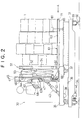
- Fig. 2 is a schematic diagram showing a loading apparatus;
- Figs. 3A and 3B are schematic diagrams showing a load carriage;
- Figs. 4A to 4D are schematic diagrams showing load transferring steps (1) through (4);
- Figs. 5A to 5C are schematic diagrams showing loading steps (1) through (3);
- Figs. 6A to 6C are schematic diagrams showing loading steps (4) through (6);
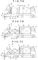
- Figs. 7A to 7C are schematic diagrams showing loading steps (7) through (9);
- Fig. 8 is a schematic diagram showing a loading step (10);
- Fig. 9 is a schematic diagram showing a working space for loading in an example wherein the present invention is applied;
- Fig. 10 is a schematic diagram showing an example of the conventional working space for loading;
- Figs. 11A to 11C are schematic diagrams showing an example of the conventional loading method;
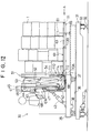
- Fig. 12 is a schematic diagram showing another loading apparatus in accordance with the present invention;
- Figs. 13A and 13B are schematic diagrams showing a coupling device;
- Figs. 14A to 14C are schematic diagrams showing a modified example of the coupling device;
- Figs. 15A to 15C are schematic diagrams illustrative of steps (1) through (3) of another loading procedure in accordance with the present invention;
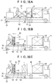
- Figs. 16A to 16C are schematic diagrams illustrative of steps (4) through (6) of another loading procedure in accordance with the present invention;
- Figs. 17A to 17C are schematic diagrams illustrative of steps (7) through (9) of another loading procedure in accordance with the present invention; and
- Figs. 18A and 18B are schematic diagrams illustrative of steps (10) and (11) of another loading procedure in accordance with the present invention.
-
Shipping equipment 10 is constituted by aload transferring apparatus 20 for transferring theload 1 from thepallet 2 and aloading apparatus 30 for stowing theload 1 onto therear deck 4A of thetruck 4.
Thetruck 4 is positioned with respect toloading apparatus 30.
Theload transferring apparatus 20 receives the palletizedload 1 supplied by theforklift 3, and then it transfers only theload 1 to theloading apparatus 30. - The
loading apparatus 30 receives theload 1 from theload transferring apparatus 20, and carries theload 1 to thetruck 4 to be loaded, and stows theload 1 on to therear deck 4A of thetruck 4. - The style of package of the palletized load is such that a slip sheet (resinous sheet) 2A is laid on the
pallet 2 and theload 1 forward of carton boxes, plastic containers, etc. is stacked on theslip sheet 2A. - The size of the
pallet 2 is approximately 2.2 m. There are two different styles of package of the palletized load as shown below: - 1. Load stacked for 2.2 m (Large package)
- 2. Load stacked only for 1.1 m, half of above (Small package)
- In the truck yard where the
shipping equipment 10 is located, a plurality oftrucks 4 are parked with the loading sides of the rear decks thereof aligned, facing against the travel passage of theloading apparatus 30. At this time, thetrucks 4 are parked in parallel topositioning lines 5. Thepositioning lines 5 are drawn at right angles to the traveling direction of theloading apparatus 30, so that the moving in/out and pushing forward direction of theloading apparatus 30 match the longitudinal direction of therear decks 4A of thetrucks 4. In this case, theloading apparatus 30 moves theload 1 in and out at right angles to the travelling direction; therefore, thelines 5 are accordingly drawn at right angles. The moving in/out direction of theload 1 may alternatively be set angularly with respect to the travelling direction; in this case, thelines 5 are accordingly drawn at an angle. - The
load transferring apparatus 20 has aload receiving conveyor 21, aload transferring pusher 22, and aload receiving deck 23. - The
load receiving conveyor 21 receives the palletizedload 1 from theforklift 3 and carries the palletized load to the front of thepusher 22. - The
load transferring pusher 22 has a sheet holding hook (not shown) which holds theslip sheet 2A of the palletized load. While holding theslip sheet 2A with the sheet holding hook, thepusher 22 pushes out only theload 1 from thesheet 2A to theload receiving deck 23. - The
load receiving deck 23 is disposed facing against the load receiving end of the travel passage of theloading apparatus 30 and it supports a load carriage 61 (to be discussed later) of theloading apparatus 30. At this time, theload carriage 61 is set so that the top surface of aslide plate 63 constituting theload carriage 61 is nearly flush with the top surface of theslip sheet 2A of the palletized load (strictly speaking, the top surface of theslide plate 63 is set slightly lower to ensure smooth transfer of theload 1 such as containers). - The side frame facing the
load receiving deck 23 of theload receiving conveyor 21 is provided with atiltable transferring plate 24. This transferringplate 24 fills the gap between theslide plate 63 of theload carriage 61 set on theload receiving deck 23 and thepallet 2 of theload receiving conveyor 21 at the time of transferring theload 1, thus preventing theload 1 from tumbling at the gap. -
- The
loading apparatus 30 is provided with a travellingcarriage 31 which travels along the loading ends of the rear decks of thetrucks 4 parked at the truck yard. The travellingcarriage 31 is equipped withwheels 33 set onrails 32 and is driven by atravel motor 34. - The
loading apparatus 30 is equipped with aloader 35 which can be moved on themovable carriage 31 in the longitudinal direction of the rear decks of the trucks 4 (moved toward or away from the loading position of therear decks 4A). The travellingcarriage 31 has aloader rail 36. Theloader 35 haswheels 37 rested on theloader rail 36 and is driven by aloader driving motor 38. - The
loading apparatus 30 has amast frame 41 installed on theloader 35. Themast frame 41 is tiltably supported on theloader 35 via a mastframe supporting shaft 42, the tilting angle thereof being changed by a tiltingcylinder 43. A liftingframe 44 is mounted liftably on themast frame 41 via a guide rail 45 and acam follower 46. The lift amount of the liftingframe 44 can be adjusted by a liftingcylinder 47. - The
loading apparatus 30 has apusher 51 and theloading carriage 61 mounted on the liftingframe 44. - The
pusher 51 has apusher plate 54 at the distal end of apantagraph 53 which is extended and contracted by apusher cylinder 52 to allow thepusher plate 54 to be moved forward and backward. Thepusher 51 pushes theload 1 on theloading carriage 61 and into the loading position. - The
loading carriage 61 has abase plate 62 fixed to the liftingframe 44 and aslide plate 63 on which theload 1 is placed and which moves toward and away from thebase plate 62, theload 1 being mounted on the slide plate 63 (Fig. 3). - The
base plate 62 is equipped with aroller 64 on which theslide plate 63 is supported in such a manner that it is free to move in and out. More specifically, when thepusher 51 pushes theload 1 on theslide plate 63 toward the loading position, theslide plate 63 is pulled out from thebase plate 62 and it moves together with theload 1 toward the loading position. - The
slide plate 63 haswheels 65 and smoothly moves on therear deck 4A of thetruck 4 via thewheels 65. Theslide plate 63 may have other means in place of thewheels 65 as long as it ensures smooth movement of theslide plate 63 on therear deck 4A of thetruck 4. For example, an air blowoff apparatus or the like which corresponds to therear deck 4A may be used instead of thewheels 65, as long as it ensures that frictional force "b" between theslide plate 63 and therear deck 4A is smaller than frictional force "a" between theload 1 and theslide plate 63 so that theslide plate 63 and theload 1 move together when thepusher 51 pushes theload 1 mounted on theslide plate 63. - The
loading apparatus 30 also has achain 66 for pulling back theslide plate 63, which has been pulled out from thebase plate 62, thechain 66 being installed to theslide plate 63 at the end of the mast frame side. Thechain 66 is wound up by a windingapparatus 67 provided on the liftingframe 44 to pull theslide plate 63 back. The wound-upchain 66 is hooked on achain receiver 68 so that it is not entangled when stowed away. The windingapparatus 67 is driven by amotor 67A. Thechain 66 laid between the windingapparatus 67 and theslide plate 63 is guided by a chain guide which is not shown. - The
slide plate 63 has, on the leading edge, alimit switch 71 for detecting a wall. When thepusher 51 pushes in theload 1 mounted on theslide plate 63, thelimit switch 71 detects that theslide plate 63 which moves together with theload 1 reaches the loading position close to and facing against the front wall on therear deck 4A (or awall 4B at the back of therear deck 4A or awall 1B of thepreceding load 1 which has been already loaded). -
Limit switches 72A through 72C are provided at three points on the bottom surface of `thebase plate 62 in the longitudinal direction of the rear deck. The limit switches 72A through 72C detect the top surface of therear deck 4A so as to enable thebase plate 62 to move on the top surface of therear deck 4A with no gap between them when theload 1 is transferred to therear deck 4A. - The
loading apparatus 30 has a measuringapparatus 81 provided on themovable carriage 31 at the end thereof on the rear deck side. While theloading apparatus 30 is moving along the travel passage from the load receiving end to thetruck 4 on to which theload 1 is stowed, the measuringapparatus 81 measures length L of the rear deck of thetruck 4 by using a laser or the like when it passes the front of therear deck 4A of thetruck 4. - The following describes the load transferring procedure taken by the
load transferring apparatus 20 and the loading procedure taken by theloading apparatus 30. Load transferring procedure (Fig. 4) - Step (1) A palletized load is placed on the load receiving conveyor 21 (Fig. 4A).
- The
load 1 which has been palletized is placed on theconveyor 21 by theforklift 3. Theconveyor 21 carries theload 1 to the front of thepusher 22. - Step (2) The
load carriage 61 of theloading apparatus 30 is moved on to the load receiving deck 23 (Fig. 4B). - The
loading apparatus 30 advances theloader 35 to receive theload 1 and moves thebase plate 62 and theslide plate 63 of theload carriage 61 on to theload receiving deck 23. Thebase plate 62 is moved down until thelimit switch 72C located on the bottom side (mast frame 41 side) detects the top surface of theload receiving deck 23, then thebase plate 62 is tilted forward until thelimit switch 72A on the leading edge side detects the top surface of theload receiving deck 23 so as to enable thebase plate 62 to move in close contact with the top surface of theload receiving deck 23. At this time, the top surface of theslide plate 63 will be almost flush with the top surface of theslip sheet 2A of the palletized load (strictly speaking, the top surface of theslide plate 63 is set slightly lower to ensure smooth transfer of theload 1 such as containers). - Step (3) Only the
load 1 mounted on thepallet 2 is received (Fig. 4C). - With the
slip sheet 2A held by the sheet holding hook (not shown) of thepusher 22 for transferring the load, thepusher 22 pushes only the load 1 (containers or carton boxes) placed on theslip sheet 2A to transfer the load to theslide plate 63. At this time, theload 1 is stacked on thepallet 2 in advance so that theload 1 is located near the leading edge of theslide plate 63. - Step (4) The
pallet 2 is ejected (Fig. 4D). - After the
load 1 has been transferred to theslide plate 63, theloading apparatus 30 moves theloader 35 back and cause thebase plate 62 and theslide plate 63 of theloading carriage 61 to go back from theload receiving deck 23. Theempty pallet 2 is then ejected by theload receiving conveyor 21. - Step (1) The
load 1 is moved to thetruck 4 to be loaded (Fig. 5A). - Before starting the loading, the worker enters into the controller of the
loading apparat 30, the type (short, standard, or long) of thetruck 4 to be loaded and the number of the position in which the truck is parked. - After the
loading apparatus 30 receives theload 1 as previously described, theloading apparatus 30 is moved to thetruck 4 on which theload 1 is to be stowed. At this time, length L of the rear deck of thetarget truck 4 is measured by the measuringapparatus 81. As described above, the measuringapparatus 81 is installed on the travelingcarriage 31 of theloading apparatus 30. While the traveling carriage is moving from theload receiving deck 23 to thetarget truck 4, the measuringapparatus 81 measures, using a laser or the like, the length of therear deck 4A as it passes the front of therear deck 4A of thetruck 4. - Based on the measurement result, the type of the
truck 4 is matched with the data which has been entered in the controller; if the data does not match, then the operator will be notified of the discrepancy. For instance, if the measurement result shows that the truck is the short type while the type the operator entered is "standard type," then the operator will be notified of this discrepancy. Accordingly, the operator must decide whether he should stow thesmall load 1 onto anothertruck 4. The following will explain this in more detail. One large load package and one small load package can be stowed on the standard type truck; therefore, based on this information, these two load packages are arranged and stacked beforehand in such a manner that the small load package includes the articles to be delivered to one type of store first while the large load package includes the articles to be delivered to other stores next. Thus, when the operator assumed that the truck was the standard type, he needs to first stow the large load package and then the matching small load package. If, however, the operator has stowed the large load package onto the short type truck by mistake, then he will not be able to stow the matching small load package. Hence, in order to avoid such a problem, the system described above enables the operator to find such a mistake, so that he will be able to decide whether he should stow the load onto another standard type truck or take the load out and replace it with another load package for the short type truck. - When the measurement result shows the coincidence with the data which has been entered in advance, the operator starts stowing the
load 1 onto thetruck 4. - As soon as the
loading apparatus 30 is set for thetarget truck 4, it automatically moves to position itself at therear deck 4A of thetarget truck 4. At this time, theloading apparatus 30 does not stop because it detects thetruck 4. It stops by referring to the dogs provided in accordance with the positioning lines 5. Accordingly, if thetruck 4 is dislocated from thepositioning line 5, then theloading apparatus 30 cannot be accurately positioned at therear deck 4A. In this case, theloading apparatus 30 is manually moved for re-positioning. - Step (2) The
loader 35 is moved and theloading carriage 61 is moved onto therear deck 4A (Fig. 5B). - The
loader 35 is moved to therear deck 4A and theload 1 and theloading carriage 61 are moved to therear deck 4A. - At this time, the length of the load k₁ + α from the back of the
deck 4A must be left. Since length L of the deck has already been measured, theloader 35 will be moved the following distance:

(a: Distance (fixed) between the edge surface of the rear deck and the leading edge of the slide plate 63) (Length k of load: 2.2 m for large load; 1.1 m for small load)
When theloading carriage 61 is moved on to therear deck 4A, the posture of thebase plate 62 is automatically adjusted so that it follows therear deck 4A. More specifically, thebase plate 62 is set slightly higher than the top surface of therear deck 4A and theloading carriage 61 is moved on to therear deck 4A with the leading edge of theloading carriage 61 slightly raised, so that theloading carriage 61 moves down until thecentral limit switch 72B mounted on thebase plate 62 detects the top surface of therear deck 4A. Theloading carriage 61 is then tilted until thelimit switch 72C located at the leading edge detects the top surface of therear deck 4A, thus enabling thebase plate 62 to move closely on the top surface of therear deck 4A. - Step (3) The
load 1 is pushed in together with thebase plate 63 by the pusher 51 (Fig. 5C). - The
load 1 is pushed by thepusher 51. When theload 1 is pushed, theslide plate 63 slides on thebase plate 62 to move on to therear deck 4A together with theload 1. - Since the
slide plate 63 is provided with thewheels 65, it can smoothly move on therear deck 4. At this time, theload 1 is in close contact with theslide plate 63 and therefore it does not shift. - The stroke of the
pusher 51 exceeds 2.2 m. The leading edge of theslide plate 63 can be accurately positioned at thewall surface 4B at the back of the rear deck by stopping the pushing operation of thepusher 51 when thelimit switch 71 located at the leading edge of theslide plate 63 detects thewall surface 4B at the back of therear deck 4A. - Alternatively, the stroke of the
pusher 51 may be set to (2.2 m + α) with the pusher be allowed to extend to the full stroke thereof. This also allows the leading edge of theslide plate 63 to be accurately positioned at thewall surface 4B at the back of the rear deck. The method using thelimit switch 71 is adopted to enable theload 1 to be accurately moved to the back of the rear deck even if the length of the rear deck was not measured accurately. - While the
load 1 is being stowed, the position of thebase plate 62 with respect to therear deck 4A is corrected. When theload 1 is stowed, therear deck 4A lowers due to the weight of the load. If thelimit switches base plate 62 described in (2) above is corrected. As an alternative, the position of thebase plate 62 may be such as to always follow the level of therear deck 4A without interrupting the loading work. In this example, the loading work is interrupted because therear deck 4A suddenly lowers. If thebase plate 62 fails to follow the sudden lowering of the rear deck in time, then thebase plate 62 and theslide plate 63 bend, possibly preventing theslide plate 63 from being smoothly pulled back. - Step (4) The
base plate 63 is pulled back and theload 1 is set down (Fig. 6A). - While keeping the
pusher 51 in the same position, theslide plate 63 is pulled back to set theload 1 down on therear deck 4A. - The
load 1 is set down without being pushed on to therear deck 4A; therefore, it does not fall forward from the frictional force generated between theload 1 and therear deck 4A. Further, theload 1 is stacked near the leading edge of theslide plate 63 and hence, theload 1 is very close to thewall surface 4B at the back of therear deck 4A. Accordingly, even if theload 1 should be about to tumble due to the step formed between theslide plate 63 and therear deck 4A, it will lean against thewall 4B which supports it. - The
load 1 is moved on to therear deck 4A, beginning with the front edge, and therear deck 4A gradually lowers. When thebase plate 62 reaches a point higher than the top surface of therear deck 4A, however, thebase plate 62 and theslide plate 63 provided on therear deck 4A both bend, preventing theslide plate 63 from being smoothly pulled back through thebase plate 62. To avoid this problem, the correction of the posture of thebase plate 62 described above is carried out in this case also in order to ensure that thebase plate 62 closely follows the top surface of therear deck 4A. - Step (5) The
pusher 51 and theloader 35 are moved back (Fig. 6B). - The
pusher 51 is contracted and theloader 35 is moved back to the home position thereof. If anotherload 1 is to be stowed, then the operator moves to the load receiving end with respect to theload transferring apparatus 20 to receive thenext load 1. - Step (6) The
next load 1 is received and carried to the truck 4 (Fig. 6C). - When stowing another load 1 (on the standard or long truck 4), the
load 1 is stacked near the leading edge of theslide plate 63 as in the case of the preceding load. - Step (7) The
loader 35 is moved (Fig. 7C). - The position in which the
loading carriage 61 is to be set on the rear deck is determined from length L of the rear deck, which has been measured in step (1) above, and length K₁ of the stowed load, then theloader 35 is moved toward therear deck 4A. - Length k₂ of the load is 1.1 m; therefore,

Moving theloader 35 by the distance given by the above formula makes it possible to move theloader 61 on to the rear deck with only a gap, k₂ + α, which is equivalent to the length of the load, left between the already stowedload 1A and the leading edge of theslide plate 63. - Step (8) The
load 1 is pushed in together with theslide plate 63 by the pusher 51 (Fig. 7B). - The
load 1 is pushed by thepusher 51, so that theload 1 and theslide plate 63 are moved on to therear deck 4A. - As described in step (3), the
pusher 51 stops pushing when thelimit switch 71 located at the leading edge of theslide plate 63 detects theload 1. - Also as in the alternative described previously, the full stroke of the
pusher 51 may be set to (2.2 m + α) and thepusher 51 may be pushed to the full stroke. - Step (9) The
slide plate 63 is pulled back and theload 1 is set down (Fig. 7C). - With the
pusher 51 kept in the same position, theslide plate 63 is pulled back and theload 1 is set down on therear deck 4A. - Step (10) The
pusher 51 and theloader 35 are moved back (Fig.8). - The
pusher 51 and theloader 35 are moved back to get ready for serving thenext truck 4. - The operations of the present embodiment will now be described.
- The
load 1 and theslide plate 63 are moved by thepusher 51 to a loading position close to and facing against the front wall (thewall surface 4B of therear deck 4A or thewall surface 1B of thepreceding load 1 which has already been stowed) on therear deck 4A, then theload 1 is stowed by pulling only theslide plate 63 out with thepusher 51 kept in the same position. Hence, even if theload 1 tumbles when theslide plate 63 is drawn out, theload 1 will be supported by the front wall on therear deck 4A, thus preventing the load from collapsing. - The
load 1 and theslide plate 63 are moved to the position near and facing against the front wall on therear deck 4A when they are pushed in by thepusher 51. This allows theload 1 to be appropriately positioned near the front wall at the back of therear deck 4A in a stable manner. The arrangement also protects theload 1 from being pushed too far as to be crushed. It also prevents theload 1 from being insufficiently pushed, leaving an insufficient loading space on therear deck 4A for thenext load 1. - The
load 1 to be placed on theslide plate 63 is moved close to therear deck 4A of theslide plate 63 in advance. Therefore, when setting theload 1 in the loading position near and facing against the front wall on therear deck 4A by pushing theload 1 by thepusher 51, theload 1 is set in the aforesaid loading position together with theslide plate 63 rather than being slid on theslide plate 63 to therear deck 4A from the middle of theslide plate 63. This prevents theload 1 from tumbling or collapsing, which may occur if theload 1 would slide on theslide plate 63 before theload 1 is set in the loading position. - In addition, the
load 1 is moved close to the leading edge of theslide plate 63 to mount it on theslide plate 63 which is then moved to the initial position (away from the back of therear deck 4A by the length of the load). Then, theload 1 can be accurately moved to the loading position at the back of therear deck 4A merely by pushing it for a certain distance by thepusher 51, thus preventing such problems as pushing theload 1 too far and crushing it or pushing it insufficiently, leaving an insufficient stowing space for the next load. - The
loading apparatus 30 has aload carriage 61 comprised of thebase plate 62 and theslide plate 63. Afterpusher 51 pushes theload 1 and theslide plate 63 to the loading position near and facing against the front wall on therear deck 4A, only theslide plate 63 can be pulled back, with thepusher 51 being kept in the same position. Thus, theloading apparatus 30 can be used to implement the functions described above. - The
slide plate 63 is provided with thewheels 65. This ensures that frictional force "b" generated between theslide plate 63 and therear deck 4A is smaller than frictional force "b" generated between theslide plate 63 and theload 1 when thepusher 51 pushes theload 1. Thus, theslide plate 63 and theload 1 can be securely moved together on the rear deck. - The
loading apparatus 30 is equipped with amovable carriage 31 which moves along the loading edge of the rear deck of thetruck 4 and aloader 35 which moves on themovable carriage 31 in the longitudinal direction of the rear deck to load thetruck 4. Hence, the usual turning space required by the conventional forklift is no longer necessary and therefore, the loading work space for theload 1 can be reduced. - In the
shipping equipment 10, the moving space at the front of the truck yard for the loading apparatus according to the present invention shown in Fig. 9 is about 40% of the space required for conventional loading apparatus shown in Fig. 10. - The second embodiment differs from the first embodiment only in one aspect; the
loading apparatus 30 has acoupling device 110. - Specifically, the
pusher 51 and theslide plate 63 can be connected through thecoupling device 110. As shown in Fig. 12 and Fig. 13, thecoupling device 110 has acoupling pin 112 provided on the distal end of the piston rod of acylinder 111 which is fixed on the side of thepusher plate 54. Thecoupling pin 112 is removably engaged in anengaging hole 113 provided in the side edge of theslide plate 63.Numeral 114 denotes a guide for thecoupling pin 112. - In this embodiment, the
slide plate 63 has twoengaging holes hole 113A is provided in the proximal end of theslide plate 63; it is used for stowing theload 1 in a large package. The engaginghole 113B is provided in the middle of theslide plate 63; it is used for stowing theload 1 in a small package. - The
pusher 51 and theslide plate 63 are coupled in accordance with either (a) or (b) described below. - (a) When stowing the
load 1 in the large package, thepusher 51 and theslide plate 63 are connected by engaging thecoupling pin 112 in theengaging hole 113A by thecylinder 111, with thepusher 51 in the home position thereof and theslide plate 63 also in the home position thereof. - (b) When stowing the
load 1 in the small package, while advancing thepusher 51, adetector 115 such as an optical sensor provided at the bottom of thepusher plate 54 detects anengaging hole display 116 such as a reflecting plate which is aligned to the engaginghole 113B in theslide plate 63. As soon as thedetector 115 detects the engaginghole display 116, thepusher 51 is stopped (Fig. 13B). Then thecylinder 111 is actuated to engage thecoupling pin 112 in the engaginghole 113B, thereby connecting thepusher 51 with theslide plate 63. - The number of the engaging
holes 113 provided in the side edge of the slide plate is not limited to two (113A and 113B). Three or more engaging holes may be provided so that the position at which thepusher 51 and theslide plate 63 are coupled can be adjusted in many positions. - Further, the
coupling device 110 may alternatively be provided with asuction pad 112A on the distal end of the piston rod of thecylinder 111 as shown in Fig. 14A, so that thesuction pad 112A is removably engaged to the side edge of theslide plate 63. - Likewise, the coupling device may alternatively be provided with an engaging hook 112B on the distal end of the piston rod of the
cylinder 111 as shown in Fig. 14B, so that the engaging hook 112B may be removably engaged to a tooth of arack 117 installed on the side edge of theslide plate 63. - As a further alternative, the
coupling device 110 may be provided with arubber pad 112C on the distal end of the piston rod of thecylinder 111 as shown in Fig. 14C, so that therubber pad 112C is pressed against the top surface of theslide plate 63 in order to connect thepusher 51 with theslide plate 63. When this occurs, thepusher 51 and theslide plate 63 are connected by thecoupling device 110 at the point where thepusher plate 54 contacts theload 1. Adetector 120 for detecting the contact between thepusher plate 54 and theload 1 is employed. Thedetector 120 has aload detecting plate 121 provided over the full width of thepusher plate 54 and alimit switch 122 which is turned ON/OFF by the sliding movement of theload detecting plate 121. Thecylinder 111 of thecoupling device 110 will extend when thelimit switch 122 turns ON and it causes therubber pad 112C to be pressed against the top surface of theslide plate 63. - In this case, the
base plate 62 is provided withrollers 64 whereon theslide plate 63 moves back and forth. More specifically, when thepusher 51 pushes theslide plate 63 connected thereto through thecoupling device 110 toward the loading position, theslide plate 63 moves toward the loading position, being pulled out from thebase plate 62 and mounting theload 1 thereon. - The following describes the loading procedure taken by the
loading apparatus 30 of the second embodiment. - (1) The load 1 (large package) is moved to the
truck 4 to be loaded (Fig. 15A). - Before starting the loading, the operator enters into the controller of
loading apparatus 30 the type (short, standard, or long) of thetruck 4 to be loaded and the number of the location where the truck is parked. - In the next step, after the
loading apparatus 30 receives theload 1 as previously described, theloading apparatus 30 is moved to thetruck 4 onto which theload 1 is to be stowed. At this time, length L of the rear deck of thetarget truck 4 is measured by the measuringapparatus 81. As described above, the measuringapparatus 81 is installed on themovable carriage 31 of theloading apparatus 30; while the movable carriage is moving from theload receiving deck 23 to thetarget truck 4, the measuringapparatus 81 measures, using a laser or the like, the length of therear deck 4A as it passes the front of therear deck 4A of thetruck 4. - Based on the measurement, there is a check of whether the type of the
truck 4 matches the data which has been entered in the controller; if it does not match, then the operator will be notified of the discrepancy. For instance, if the measurement result shows that the truck is the short type while the type the operator entered is "standard type," then the operator will be notified of this discrepancy, enabling the operator to recognize that he will not be able to stow thesmall load 1 next. Accordingly, the operator must decide whether he should stow thesmall load 1 onto anothertruck 4. The following will explain this in more detail. One large load package and one small load package can be stowed on the standard type truck; therefore, based on this information, these two load packages are arranged and stacked beforehand in such a manner that the small load package includes the articles to be delivered to certain stores first while the large load package includes the articles to be delivered to other stores next. Thus, when the operator assumed that the truck was the standard type, he knew he needed to first stow the large load package and then the matching small load package. If, however, the operator has stowed the large load package onto the short type truck by mistake, then he will not be able to stow the matching small load package. Hence, in order to avoid such a problem, the system described above enables the operator to find such a mistake, so that he will be able to decide whether he should stow the load onto another standard type truck or take the load out and replace it with another load package for the short type truck. - When the measurement result shows the coincidence with the data which has been entered in advance, the operator starts stowing the
load 1 onto thetruck 4. - As soon as the
loading apparatus 30 is set for thetarget truck 4, it automatically moves to position itself at therear deck 4A of thetarget truck 4. At this time, theloading apparatus 30 does not stop because it detects thetruck 4; it stops by referring to the dogs provided in accordance with the positioning lines 5. Accordingly, if thetruck 4 is dislocated from thepositioning line 5, then theloading apparatus 30 cannot be accurately positioned at therear deck 4A. In this case, theloading apparatus 30 is manually moved for re-positioning. - (2) The
loader 35 is moved and theloading carriage 61 is moved onto therear deck 4A (Fig. 15B). - The
loader 35 is moved to therear deck 4A and theload 1 and theloading carriage 61 are moved onto therear deck 4A. - At this time, the length of the load k₁ + α from the back of the
deck 4A must be left. Since length L of the deck has already been measured in (1) above, theloader 35 will be moved by the following distance:

(a: Distance (fixed) between the edge surface of the rear deck and the leading edge of the slide plate 63) (Length k of load: 2.2 m for large load; 1.1 m for small load)
When theloading carriage 61 is moved onto therear deck 4A, the position of thebase plate 62 is automatically adjusted so that it follows therear deck 4A. More specifically, thebase plate 62 is set slightly higher than the top surface of therear deck 4A and theloading carriage 61 is moved onto therear deck 4A with the leading edge of theloading carriage 61 slightly raised, so that theloading carriage 61 moves down until thecentral limit switch 72B mounted on thebase plate 62 detects the top surface of therear deck 4A. Theloading carriage 61 is then tilted until thelimit switch 72C located at the leading edge detects the top surface of therear deck 4A, thus enabling thebase plate 62 to move closely on the top surface of therear deck 4A. - While the
load carriage 61 is being moved onto therear deck 4A, thepusher 51 and theslide plate 63 are linked through thecoupling device 110. To be specific, thecoupling pin 112 is engaged in theengaging hole 113A by thecylinder 111. - (3) The
base plate 62 is pushed in by the pusher 51 (Fig. 15C). - The
slide plate 63 is pushed by thepusher 51 via thecoupling device 110. Theslide plate 63 slides on thebase plate 62 to move on to therear deck 4A together with theload 1. - Since the
slide plate 63 is provided with thewheels 65, it can smoothly move on therear deck 4. At this time, theload 1 is in close contact with theslide plate 63 and therefore it does not shift. - The stroke of the
pusher 51 exceeds 2.2 m. The leading edge of theslide plate 63 can be accurately positioned at thewall surface 4B at the back of the rear deck by stopping the pushing operation of thepusher 51 when thelimit switch 71 located at the leading edge of theslide plate 63 detects thewall surface 4B at the back of therear deck 4A. - Alternatively, the stroke of the
pusher 51 may be set to (2.2 m + α) allowing the pusher to extend to the full stroke thereof. This also allows the leading edge of theslide plate 63 to be accurately positioned at thewall surface 4B at the back of the rear deck. The method based on thelimit switch 71 is adopted to enable theload 1 to be accurately moved to the back of the rear deck even if the length of the rear deck was not measured accurately. - Also while the
load 1 is being stowed, the position of thebase plate 62 with respect to therear deck 4A is corrected. When theload 1 is stowed, therear deck 4A lowers due to the weight of the load; if the limit switches detect such lowering, then the loading work is interrupted and the position of thebase plate 62 described in (2) above is corrected. As an alternative, the position of thebase plate 62 may be made to always follow the level of therear deck 4A without interrupting the loading work. In this example, the loading work is interrupted because therear deck 4A suddenly lowers; and if thebase plate 62 fails to follow the sudden lowering of the rear deck in time, then thebase plate 62 and theslide plate 63 bend, possibly preventing theslide plate 63 from being smoothly pulled back. - (4) The engagement formed between the
pusher 51 and theslide plate 63 by thecoupling device 110 is released and theslide plate 63 is pulled back, then theload 1 is set down (Fig. 16A). To be specific, thecoupling pin 112 is drawn out from the engaginghole 113A by thecylinder 111. - While keeping the
pusher 51 in the same position, theslide plate 63 is pulled back to set theload 1 down on therear deck 4A. - The
load 1 is set down without being pushed on therear deck 4A. It does not fall forward from the frictional force generated between theload 1 and therear deck 4A. Further, theload 1 is stacked near the leading edge of theslide plate 63 and hence, theload 1 is very close to thewall surface 4B at the back of therear deck 4A. Accordingly, even if theload 1 is about to tumble due to the step formed between theslide plate 63 and therear deck 4A, it will lean against thewall 4B which supports it and prevents tumbling. - The
load 1 is moved on to therear deck 4A, beginning with the front edge, and therear deck 4A gradually lowers. When thebase plate 62 reaches a point higher than the top surface of therear deck 4A, however, thebase plate 62 and theslide plate 63 provided on therear deck 4A both bend, preventing theslide plate 63 from being smoothly pulled back through thebase plate 62. To avoid this problem, the correction of the position of thebase plate 62 described in (2) above is carried out in this case also in order to ensure that thebase plate 62 closely follows the top surface of therear deck 4A. - (5) The
pusher 51 and theloader 35 are moved back (Fig. 16B). - The
pusher 51 is contracted and theloader 35 is moved back to the home position thereof. If anotherload 1 is to be stowed, then the operator moves to the load receiving end with respect to theload transferring apparatus 20 to receive thenext load 1. - (6) The next load 1 (small package) is received and carried to the truck 4 (Fig. 16C).
- When stowing another load 1 (on the standard or long truck 4), the
load 1 is stacked near the leading edge of theslide plate 63 as in the case of the preceding load. - (7) The
loader 35 is moved (Fig. 17A). - The position in which the
loading carriage 61 is to be set on the rear deck is determined from length L of the rear deck, which has been measured in step (1) above, and length K₁ of the stowed load, then theloader 35 is moved toward therear deck 4A. - Length k₂ of the load is 1.1 m; therefore,

Moving theloader 35 by the distance given by the above formula makes it possible to move theloader 61 on to the rear deck with only a gap, k₂ + α, which is equivalent to the length of the load, left between the already stowedload 1A and the leading edge of theslide plate 63. - (8) The
pusher 51 and theslide plate 63 are connected by the coupling device 110 (Fig. 17B). - The
pusher 51 is advanced and when thedetector 115 provided at the bottom of thepusher plate 54 detects the engaginghole display 116 on theslide plate 63, thepusher 51 is stopped. Thecylinder 111 is actuated to engage thecoupling pin 112 in the engaginghole 113B. - (9) The
slide plate 63 is pushed in by the pusher 51 (Fig. 17C). - The
base plate 62 is pushed by thepusher 51 via thecoupling device 110, so that theload 1 and theslide plate 63 are moved onto therear deck 4A. - As described in step (3), the
pusher 51 stops pushing when thelimit switch 71 located at the leading edge of theslide plate 63 detects theload 1. - Also as in the alternative described previously, the full stroke of the
pusher 51 may be set to (2.2 m + α) and thepusher 51 may be pushed to the full stroke. - (10) The engagement formed between the
pusher 51 and theslide plate 63 by thecoupling device 110 is released and theslide plate 63 is pulled back, then theload 1 is set down (Fig. 18A). To be specific, thecoupling pin 112 is drawn out from the engaginghole 113B by thecylinder 111. - With the
pusher 51 kept in the same position, theslide plate 63 is pulled back and theload 1 is set down on therear deck 4A. - (11) The
pusher 51 and theloader 35 are moved back (Fig. 18B). - The
pusher 51 and theloader 53 are moved back to get ready for serving thenext truck 4. - The operations of the present embodiment will now be described.
- The
load 1 and theslide plate 63 are moved by thepusher 51 to a loading position close to and facing against the front wall (thewall surface 4B of therear deck 4A or thewall surface 1B of thepreceding load 1 which has already been stowed) on therear deck 4A. Theload 1 is then stowed by pulling out only theslide plate 63 out with thepusher 51 kept in the same position. Hence, even if theload 1 tumbles when theslide plate 63 is drawn out, theload 1 will be supported by the front wall on therear deck 4A, thus preventing the load from collapsing. - The
load 1 and theslide plate 63 are moved to the position near and facing against the front wall on therear deck 4A when they are pushed in by thepusher 51. This allows theload 1 to be appropriately positioned near the front wall at the back of therear deck 4A in a stable manner. The arrangement also protects theload 1 from being pushed in excessively and crushed. It also prevents theload 1 from being insufficiently pushed in, leaving an insufficient loading space on therear deck 4A for thenext load 1. - When stowing a load by the
pusher 51, thepusher 51 is coupled to theslide plate 63 to securely push theslide plate 63 in to prevent aload 1 from being pushed out with theslide plate 63 stationary, resulting in the collapse of theload 1 or the like even when theload 1 is light in weight. This means that thepusher 51 is capable of positioning the load on theslide plate 63 in the loading position in a secure and stable manner by securely pushing theslide plate 63 in. - The
load 1 to be placed on theslide plate 63 is moved to therear deck side 4A of theslide plate 63 beforehand and thepusher 51 is coupled to theslide plate 63, and then theslide plate 63 is pushed in. In this way, theslide plate 63 is pushed in by thepusher 51 to set theload 1 in the loading position close to and facing against the front wall on therear deck 4A. At this time, theload 1 is set in the aforesaid loading position together with theslide plate 63 rather than being slid onto therear deck 4A from the middle point of theslide plate 63. Hence, falling or collapse of theload 1, which may occur if theload 1 is to slide on theslide plate 63, can be avoided in the stage before theload 1 is settled in the loading position. - Furthermore, the
load 1 can be accurately moved to the loading position at the back of the rear deck by moving theload 1 to the leading edge of theslide plate 63 and stacking it there, moving theslide plate 63 to an initial position (away from the back of therear deck 4A by the length of the load), and simply giving the slide plate 63 a certain amount of push by thepusher 51. This prevents theload 1 from being crushed from too much push or being insufficiently pushed in, leaving an insufficient loading space for the next load. - The
load carriage 61 of theloading apparatus 30 has thebase plate 62 and theslide plate 63. Theslide plate 63 is connectable to thepusher 51. Accordingly, after thepusher 51 is coupled to theslide plate 63, theload 1 and theslide plate 63 are pushed in until they reach the loading position near and facing against the front wall on therear deck 4A by thepusher 51. Only theslide plate 63 can be pulled back with the pusher kept in the same position by disconnecting thepusher 51 from theslide plate 63. Thus, the loading apparatus can be used to implement the procedures described above. - While the preferred embodiments of the invention have been described in detail with reference to the drawings, they are by no means limitative, and various changes and modifications are possible without departing from the scope and spirit of the invention.
- Although the invention has been illustrated and described with respect to several exemplary embodiments thereof, it should be understood by those skilled in the art that the foregoing and various other changes, omissions and additions may be made to the present invention without departing from the spirit and scope thereof. Therefore, the present invention should not be understood as limited to the specific embodiment set out above but to include all possible embodiments which can be embodied within a scope encompassed and equivalents thereof with respect to the feature set out in the appended claims.
Short: 1 large package
Standard: 1 large package and 1 small package
Long: 2 large packages
Claims (8)
- A method for stowing a load in a load stacking position on a rear deck, wherein the load is mounted on a slide plate and comprising the steps of;
pushing the load with a pusher to a push-in position until said load and said slide plate reach a load stacking position which is close to and facing against a front wall on the rear deck; and
transferring the load to the load stacking position by pulling said slide plate back from said load stacking position with said pusher kept in the push-in position. - A method for stowing a load according to Claim 1, comprising the steps of;
stacking the load on the rear deck side of said slide plate;
positioning the leading edge of said slide plate away from said front wall, which is said load stacking position, by the length of said load; then
pushing in said slide plate by use of said pusher. - An apparatus for stowing a load comprising:
a loader which moves toward and away from a load stacking position on a rear deck;
a load carriage which is provided on said loader and on which a load is mounted; and
a pusher which is provided on said loader and which pushes the load on said load carriage to said load stacking position;
said load carriage comprising a base plate, which is fixed to said loader, and a slide plate which moves toward and away from said base plate. - An apparatus for stowing a load according to Claim 3, wherein said slide plate is equipped with a wheel which rolls on said rear deck.
- A method for stowing a load in a load stacking position on a rear deck, wherein the load is mounted on a slide plate, the method comprising the steps of;
linking a pusher to said slide plate to push said slide plate by said pusher to a push-in position until said load and said slide plate reach a load stacking position which is close to and facing against a front wall on said rear deck; and
releasing the engagement between said pusher and said slide plate, transferring said load to said load stacking position by pulling said slide plate back from said load stacking position with said pusher kept in the push-in position. - A method for stowing a load according to Claim 5, comprising the steps of;
linking said pusher to said slide plate after said pusher reaches to a position which contacts the load. - A method for stowing a load according to Claim 5, comprising the steps of;
stacking said load on the rear deck side of said slide plate;
positioning the leading edge of said slide plate away from said front wall, which is said load stacking position, by the length of said load; then
pushing said slide plate in with said pusher. - An apparatus for stowing a load, said apparatus comprising:
a loader which moves toward and away from a load stacking position on a rear deck;
a load carriage which is provided on said loader and on which a load is mounted; and
a pusher which is connectable to said slide plate and which is provided on said loader and which moves the load on said load carriage to said loading position;
said load carriage comprising a base plate, which is fixed to said loader, and a slide plate which moves toward and away from said base plate.
Applications Claiming Priority (4)
| Application Number | Priority Date | Filing Date | Title |
|---|---|---|---|
| JP5323402A JP2868402B2 (en) | 1993-11-30 | 1993-11-30 | Load loading method and device |
| JP323402/93 | 1993-11-30 | ||
| JP259006/94 | 1994-09-29 | ||
| JP25900694A JP3558386B2 (en) | 1994-09-29 | 1994-09-29 | Load loading method and device |
Publications (2)
| Publication Number | Publication Date |
|---|---|
| EP0655403A1 true EP0655403A1 (en) | 1995-05-31 |
| EP0655403B1 EP0655403B1 (en) | 1998-10-28 |
Family
ID=26543921
Family Applications (1)
| Application Number | Title | Priority Date | Filing Date |
|---|---|---|---|
| EP94118754A Expired - Lifetime EP0655403B1 (en) | 1993-11-30 | 1994-11-29 | Method and apparatus for stowing a load |
Country Status (3)
| Country | Link |
|---|---|
| US (1) | US5577873A (en) |
| EP (1) | EP0655403B1 (en) |
| DE (1) | DE69414226T2 (en) |
Cited By (17)
| Publication number | Priority date | Publication date | Assignee | Title |
|---|---|---|---|---|
| DE19740156A1 (en) * | 1997-09-12 | 1999-03-18 | Eckhard Buhl | Process for loading compressible load onto a truck loading unit |
| WO2006044371A1 (en) * | 2004-10-12 | 2006-04-27 | Nathan Frankel | Loading assembly for transport containers |
| GB2451631A (en) * | 2007-08-04 | 2009-02-11 | Dunn Brothers | Container loading apparatus |
| WO2009107084A1 (en) * | 2008-02-27 | 2009-09-03 | Colin Gower Scriven | Loading of a container |
| US7588406B2 (en) | 2004-10-12 | 2009-09-15 | Fastek, Llc | Loading assembly for transport containers, and related method of use |
| US7744330B2 (en) | 2008-06-13 | 2010-06-29 | Blue Tee Corporation | Container packer system and method |
| WO2011098966A1 (en) * | 2010-02-12 | 2011-08-18 | Van Der Walt, Louis, Stephanus | A load truck and a method of offloading a load unit |
| WO2011138016A1 (en) * | 2010-05-04 | 2011-11-10 | Maschinenfabrik Möllers Gmbh | Device for loading or unloading load units |
| EP2455311A1 (en) * | 2010-11-22 | 2012-05-23 | Beheer 141 B.V. | Method for loading and unloading an elongated container |
| US9056731B1 (en) | 2008-06-13 | 2015-06-16 | Advanced Steel Recovery, Llc | Container packer system and method |
| EP2483189A4 (en) * | 2009-09-29 | 2016-10-19 | Jouni Järvensivu | Method and device for filling a container |
| EP3251987A1 (en) * | 2016-05-31 | 2017-12-06 | Siemens Aktiengesellschaft | Loading system for piece goods with transportable loading device |
| CN108082944A (en) * | 2017-12-21 | 2018-05-29 | 深圳市鸿益达供应链科技有限公司 | Portable palletizing system |
| WO2019145403A1 (en) * | 2018-01-25 | 2019-08-01 | Heinz Buse | Device for loading a load carrier with piece goods and method for loading a load carrier |
| WO2020079179A1 (en) * | 2018-10-17 | 2020-04-23 | Dücker Group GmbH | Fully automated end-face loading of a truck using a transport vehicle |
| CN111776779A (en) * | 2020-07-16 | 2020-10-16 | 黔西南州乐呵化工有限责任公司 | Loading method |
| DE102020115894A1 (en) | 2020-06-16 | 2021-12-16 | Ltw Intralogistics Gmbh | DEVICE AND PROCEDURE FOR LOADING A LOADING AREA WITH A MULTIPLE NUMBER OF SIMILAR GOODS AND A LOADING SYSTEM |
Families Citing this family (23)
| Publication number | Priority date | Publication date | Assignee | Title |
|---|---|---|---|---|
| DE19712289A1 (en) * | 1997-03-24 | 1998-10-01 | Otmar Fahrion | Loading device |
| US20050053451A1 (en) * | 1999-02-11 | 2005-03-10 | Pierre Gagnon | Vehicle loading and unloading system |
| US6571693B1 (en) * | 1999-10-06 | 2003-06-03 | Al-Jon | Vehicle recycling system and method |
| US6312206B1 (en) | 2000-02-22 | 2001-11-06 | Planters Cotton Oil Mill, Inc. | Method and apparatus for loading bulk materials |
| FI109588B (en) * | 2000-03-27 | 2002-09-13 | Cimcorp Oy | Processing arrangements for commodity units and procedure for processing commodity units |
| US7695235B1 (en) * | 2002-07-19 | 2010-04-13 | Rallis John H | Automated warehousing and cargo loading system |
| US7909562B2 (en) * | 2006-08-08 | 2011-03-22 | C&S Wholesale Grocers, Inc. | Material handling apparatus |
| US7837428B2 (en) | 2007-03-05 | 2010-11-23 | SA Recycling LLC | Methods and apparatuses for freight container loading |
| US8668425B2 (en) * | 2007-03-05 | 2014-03-11 | SA Recycling LLC | Methods and apparatus for freight container loading |
| US7744332B2 (en) * | 2007-06-21 | 2010-06-29 | Martin Thomas W | System for storing and temporarily relocating a trash container |
| US8257007B2 (en) * | 2007-07-27 | 2012-09-04 | Container Stuffers, Llc | Cargo loader |
| US8834090B1 (en) * | 2009-02-05 | 2014-09-16 | Albert C. Callens | Grappling fork attachment system |
| DE102009022527A1 (en) * | 2009-05-25 | 2010-12-09 | Siemens Aktiengesellschaft | Device for loading and unloading loading units |
| US8784031B2 (en) * | 2010-01-04 | 2014-07-22 | Container Stuffers, Llc | Cargo loader |
| DE102010042705A1 (en) | 2010-10-20 | 2012-04-26 | Siemens Aktiengesellschaft | Device for treating piece goods of a transport unit, in particular a swap body |
| US8857080B1 (en) * | 2011-06-16 | 2014-10-14 | Frank J Sutter | Transfer bucket and ejector assembly for a front end loader vehicle |
| US9738464B1 (en) | 2012-10-18 | 2017-08-22 | Scott Sakajian | System and method for protecting containers from damage during loading |
| CN106604886B (en) | 2014-09-15 | 2019-06-18 | 克朗设备公司 | Fork truck with optics cargo sensing structure |
| CN104816959B (en) * | 2015-03-17 | 2018-02-27 | 青岛德和丰科贸有限公司 | Full-automatic container carloader |
| DE102017004641A1 (en) * | 2017-05-15 | 2018-11-29 | Giesecke+Devrient Currency Technology Gmbh | Filling of value document cassettes |
| AU2018250517B2 (en) * | 2017-10-20 | 2024-04-11 | YGCC Holdings Pty Ltd | Apparatus for use in unpacking shipping containers |
| US11358843B2 (en) * | 2019-05-20 | 2022-06-14 | Manitou Equipment America, Llc | Retracting carriage attachment |
| US20230192425A1 (en) * | 2021-12-17 | 2023-06-22 | Simec Systems Oy | Apparatus and method for unloading and loading a transport unit |
Citations (6)
| Publication number | Priority date | Publication date | Assignee | Title |
|---|---|---|---|---|
| AT220547B (en) * | 1960-06-24 | 1962-03-26 | Walter Dipl Ing Kupka | Lifting carriages for industrial trucks |
| US3710961A (en) * | 1969-06-17 | 1973-01-16 | Establissements J Berthelat Et | Transfer device |
| DE2808922A1 (en) * | 1978-03-02 | 1979-09-13 | Interplan | Palletised goods vehicle loader - has turntable for height adjustable fork movable over twice pallet length |
| US4171178A (en) * | 1977-03-31 | 1979-10-16 | Maschinenfabrik E. Mollers Gmbh & Co. | Apparatus for automatically handling stacks of bags |
| DE4140452A1 (en) * | 1990-12-06 | 1992-06-11 | Ruediger Staege | Automatic loader for pallets onto lorries or trailers - consists of machine with four or six prongs, collector platform and rollers |
| DE4226870A1 (en) * | 1991-08-12 | 1993-02-18 | Ruediger Staege | Pallet handling appts. for transfer between store and lorry - has height adjusting transfer platform on support rails and with self-locating forks to grip pallets |
Family Cites Families (7)
| Publication number | Priority date | Publication date | Assignee | Title |
|---|---|---|---|---|
| US2574045A (en) * | 1948-02-02 | 1951-11-06 | Sidney D Lapham | Fork lift truck |
| GB966227A (en) * | 1960-11-28 | 1964-08-06 | Raymond Corp | Load handling truck |
| DE2205505C3 (en) * | 1972-02-05 | 1975-07-03 | Foerdertechnische Forschungsgesellschaft Mbh, 2000 Hamburg | Device for loading containers with piece goods, preferably loaded pallets |
| JPS5213271A (en) * | 1975-07-21 | 1977-02-01 | Central Conveyor Kk | Extrusion mechanism in a conveyor apparatus |
| CA1166997A (en) * | 1981-07-15 | 1984-05-08 | Gerardus J. Brouwer | Pallet retrieving mechanism for forklift vehicle |
| US4995785A (en) * | 1986-09-12 | 1991-02-26 | Kornelis Platteschorre | Egg carton stacking-loading device and method |
| GB8716356D0 (en) * | 1987-07-10 | 1987-08-19 | Sanderson Forklifts Ltd | Load-handling vehicles |
-
1994
- 1994-11-29 US US08/346,072 patent/US5577873A/en not_active Expired - Fee Related
- 1994-11-29 EP EP94118754A patent/EP0655403B1/en not_active Expired - Lifetime
- 1994-11-29 DE DE69414226T patent/DE69414226T2/en not_active Expired - Fee Related
Patent Citations (6)
| Publication number | Priority date | Publication date | Assignee | Title |
|---|---|---|---|---|
| AT220547B (en) * | 1960-06-24 | 1962-03-26 | Walter Dipl Ing Kupka | Lifting carriages for industrial trucks |
| US3710961A (en) * | 1969-06-17 | 1973-01-16 | Establissements J Berthelat Et | Transfer device |
| US4171178A (en) * | 1977-03-31 | 1979-10-16 | Maschinenfabrik E. Mollers Gmbh & Co. | Apparatus for automatically handling stacks of bags |
| DE2808922A1 (en) * | 1978-03-02 | 1979-09-13 | Interplan | Palletised goods vehicle loader - has turntable for height adjustable fork movable over twice pallet length |
| DE4140452A1 (en) * | 1990-12-06 | 1992-06-11 | Ruediger Staege | Automatic loader for pallets onto lorries or trailers - consists of machine with four or six prongs, collector platform and rollers |
| DE4226870A1 (en) * | 1991-08-12 | 1993-02-18 | Ruediger Staege | Pallet handling appts. for transfer between store and lorry - has height adjusting transfer platform on support rails and with self-locating forks to grip pallets |
Cited By (25)
| Publication number | Priority date | Publication date | Assignee | Title |
|---|---|---|---|---|
| DE19740156A1 (en) * | 1997-09-12 | 1999-03-18 | Eckhard Buhl | Process for loading compressible load onto a truck loading unit |
| US7588406B2 (en) | 2004-10-12 | 2009-09-15 | Fastek, Llc | Loading assembly for transport containers, and related method of use |
| WO2006044371A1 (en) * | 2004-10-12 | 2006-04-27 | Nathan Frankel | Loading assembly for transport containers |
| US7172382B2 (en) | 2004-10-12 | 2007-02-06 | Nathan Frankel | Loading assembly for transport containers, and related method of use |
| US7699575B2 (en) | 2004-10-12 | 2010-04-20 | Nathan Frankel | Loading assembly for transport containers and related method of use |
| GB2451631A (en) * | 2007-08-04 | 2009-02-11 | Dunn Brothers | Container loading apparatus |
| WO2009107084A1 (en) * | 2008-02-27 | 2009-09-03 | Colin Gower Scriven | Loading of a container |
| US7744330B2 (en) | 2008-06-13 | 2010-06-29 | Blue Tee Corporation | Container packer system and method |
| US11383942B1 (en) | 2008-06-13 | 2022-07-12 | Advanced Steel Recovery, Llc | Container packer system and method |
| US10954086B1 (en) | 2008-06-13 | 2021-03-23 | Advanced Steel Recovery, Llc | Container packer system and method |
| US8061950B2 (en) | 2008-06-13 | 2011-11-22 | GEFOO, Inc. | Container packer system and method |
| US10737891B1 (en) | 2008-06-13 | 2020-08-11 | Advanced Steel Recovery, Llc | Container packer system and method |
| US10059538B1 (en) | 2008-06-13 | 2018-08-28 | Advanced Steel Recovery, Llc | Container packer system and method |
| US9056731B1 (en) | 2008-06-13 | 2015-06-16 | Advanced Steel Recovery, Llc | Container packer system and method |
| EP2483189A4 (en) * | 2009-09-29 | 2016-10-19 | Jouni Järvensivu | Method and device for filling a container |
| CN102906004A (en) * | 2010-02-12 | 2013-01-30 | 多伦·莫什 | A load truck and a method of offloading a load unit |
| WO2011098966A1 (en) * | 2010-02-12 | 2011-08-18 | Van Der Walt, Louis, Stephanus | A load truck and a method of offloading a load unit |
| WO2011138016A1 (en) * | 2010-05-04 | 2011-11-10 | Maschinenfabrik Möllers Gmbh | Device for loading or unloading load units |
| EP2455311A1 (en) * | 2010-11-22 | 2012-05-23 | Beheer 141 B.V. | Method for loading and unloading an elongated container |
| EP3251987A1 (en) * | 2016-05-31 | 2017-12-06 | Siemens Aktiengesellschaft | Loading system for piece goods with transportable loading device |
| CN108082944A (en) * | 2017-12-21 | 2018-05-29 | 深圳市鸿益达供应链科技有限公司 | Portable palletizing system |
| WO2019145403A1 (en) * | 2018-01-25 | 2019-08-01 | Heinz Buse | Device for loading a load carrier with piece goods and method for loading a load carrier |
| WO2020079179A1 (en) * | 2018-10-17 | 2020-04-23 | Dücker Group GmbH | Fully automated end-face loading of a truck using a transport vehicle |
| DE102020115894A1 (en) | 2020-06-16 | 2021-12-16 | Ltw Intralogistics Gmbh | DEVICE AND PROCEDURE FOR LOADING A LOADING AREA WITH A MULTIPLE NUMBER OF SIMILAR GOODS AND A LOADING SYSTEM |
| CN111776779A (en) * | 2020-07-16 | 2020-10-16 | 黔西南州乐呵化工有限责任公司 | Loading method |
Also Published As
| Publication number | Publication date |
|---|---|
| DE69414226T2 (en) | 1999-03-25 |
| DE69414226D1 (en) | 1998-12-03 |
| EP0655403B1 (en) | 1998-10-28 |
| US5577873A (en) | 1996-11-26 |
Similar Documents
| Publication | Publication Date | Title |
|---|---|---|
| EP0655403B1 (en) | Method and apparatus for stowing a load | |
| EP0615925B1 (en) | Article loading apparatus and method therefor | |
| JP4586990B2 (en) | Goods storage equipment | |
| EP1728738B1 (en) | Article transport facility and a method of operating the facility | |
| EP0407162B1 (en) | Carriage for the transportation of a cylindrical object | |
| US5524747A (en) | Method and apparatus for taking up articles | |
| JP2000508611A (en) | Telescopic loading and unloading machine for trailers with user donation | |
| KR100308870B1 (en) | Stacker Crane | |
| US2785818A (en) | Stripper mechanism for lift trucks | |
| AU2054899A (en) | Loading and unloading system for cargo trucks, their trailers, transport containers and the like | |
| GB2276874A (en) | System for storage,retrieval and supply of steel plates | |
| JP4552766B2 (en) | Goods storage facility | |
| US7014198B2 (en) | Low profile cart and automatic unloading system | |
| JP3128358B2 (en) | Automatic picking method and apparatus for stacking sheet packages | |
| JP2868402B2 (en) | Load loading method and device | |
| JP3558386B2 (en) | Load loading method and device | |
| US20160039620A1 (en) | Unloading a Cylindrical Body from a Pallet | |
| JP2973817B2 (en) | Automatic warehouse loading / unloading device | |
| US5127789A (en) | Apparatus for loading and unloading pallets | |
| JPS636441B2 (en) | ||
| JPH0912139A (en) | Winding roll vertical piling palletizer and method for vertically piling winding roll onto pallet | |
| JP3314558B2 (en) | Mechanical parking device | |
| JPH02308076A (en) | Housing device for vehicle or the like | |
| JPH042283Y2 (en) | ||
| JPH0540008Y2 (en) |
Legal Events
| Date | Code | Title | Description |
|---|---|---|---|
| PUAI | Public reference made under article 153(3) epc to a published international application that has entered the european phase |
Free format text: ORIGINAL CODE: 0009012 |
|
| AK | Designated contracting states |
Kind code of ref document: A1 Designated state(s): CH DE LI SE |
|
| 17P | Request for examination filed |
Effective date: 19950802 |
|
| 17Q | First examination report despatched |
Effective date: 19961203 |
|
| GRAG | Despatch of communication of intention to grant |
Free format text: ORIGINAL CODE: EPIDOS AGRA |
|
| GRAG | Despatch of communication of intention to grant |
Free format text: ORIGINAL CODE: EPIDOS AGRA |
|
| GRAG | Despatch of communication of intention to grant |
Free format text: ORIGINAL CODE: EPIDOS AGRA |
|
| GRAH | Despatch of communication of intention to grant a patent |
Free format text: ORIGINAL CODE: EPIDOS IGRA |
|
| GRAH | Despatch of communication of intention to grant a patent |
Free format text: ORIGINAL CODE: EPIDOS IGRA |
|
| GRAA | (expected) grant |
Free format text: ORIGINAL CODE: 0009210 |
|
| AK | Designated contracting states |
Kind code of ref document: B1 Designated state(s): CH DE LI SE |
|
| REG | Reference to a national code |
Ref country code: CH Ref legal event code: EP |
|
| REF | Corresponds to: |
Ref document number: 69414226 Country of ref document: DE Date of ref document: 19981203 |
|
| REG | Reference to a national code |
Ref country code: CH Ref legal event code: NV Representative=s name: BOVARD AG PATENTANWAELTE |
|
| PLBE | No opposition filed within time limit |
Free format text: ORIGINAL CODE: 0009261 |
|
| STAA | Information on the status of an ep patent application or granted ep patent |
Free format text: STATUS: NO OPPOSITION FILED WITHIN TIME LIMIT |
|
| PGFP | Annual fee paid to national office [announced via postgrant information from national office to epo] |
Ref country code: SE Payment date: 19991019 Year of fee payment: 6 |
|
| 26N | No opposition filed | ||
| PGFP | Annual fee paid to national office [announced via postgrant information from national office to epo] |
Ref country code: DE Payment date: 19991115 Year of fee payment: 6 |
|
| PGFP | Annual fee paid to national office [announced via postgrant information from national office to epo] |
Ref country code: CH Payment date: 19991119 Year of fee payment: 6 |
|
| PG25 | Lapsed in a contracting state [announced via postgrant information from national office to epo] |
Ref country code: SE Free format text: THE PATENT HAS BEEN ANNULLED BY A DECISION OF A NATIONAL AUTHORITY Effective date: 20001129 |
|
| PG25 | Lapsed in a contracting state [announced via postgrant information from national office to epo] |
Ref country code: LI Free format text: LAPSE BECAUSE OF NON-PAYMENT OF DUE FEES Effective date: 20001130 Ref country code: CH Free format text: LAPSE BECAUSE OF NON-PAYMENT OF DUE FEES Effective date: 20001130 |
|
| REG | Reference to a national code |
Ref country code: CH Ref legal event code: PL |
|
| EUG | Se: european patent has lapsed |
Ref document number: 94118754.4 |
|
| PG25 | Lapsed in a contracting state [announced via postgrant information from national office to epo] |
Ref country code: DE Free format text: LAPSE BECAUSE OF NON-PAYMENT OF DUE FEES Effective date: 20010801 |