EP0655842A2 - High speed variable length code decoding apparatus - Google Patents
High speed variable length code decoding apparatus Download PDFInfo
- Publication number
- EP0655842A2 EP0655842A2 EP94118771A EP94118771A EP0655842A2 EP 0655842 A2 EP0655842 A2 EP 0655842A2 EP 94118771 A EP94118771 A EP 94118771A EP 94118771 A EP94118771 A EP 94118771A EP 0655842 A2 EP0655842 A2 EP 0655842A2
- Authority
- EP
- European Patent Office
- Prior art keywords
- length
- codeword
- decoding
- variable length
- bit
- Prior art date
- Legal status (The legal status is an assumption and is not a legal conclusion. Google has not performed a legal analysis and makes no representation as to the accuracy of the status listed.)
- Ceased
Links
Images


Classifications
-
- H—ELECTRICITY
- H03—ELECTRONIC CIRCUITRY
- H03M—CODING; DECODING; CODE CONVERSION IN GENERAL
- H03M7/00—Conversion of a code where information is represented by a given sequence or number of digits to a code where the same, similar or subset of information is represented by a different sequence or number of digits
- H03M7/30—Compression; Expansion; Suppression of unnecessary data, e.g. redundancy reduction
- H03M7/40—Conversion to or from variable length codes, e.g. Shannon-Fano code, Huffman code, Morse code
- H03M7/42—Conversion to or from variable length codes, e.g. Shannon-Fano code, Huffman code, Morse code using table look-up for the coding or decoding process, e.g. using read-only memory
- H03M7/425—Conversion to or from variable length codes, e.g. Shannon-Fano code, Huffman code, Morse code using table look-up for the coding or decoding process, e.g. using read-only memory for the decoding process only
-
- H—ELECTRICITY
- H04—ELECTRIC COMMUNICATION TECHNIQUE
- H04N—PICTORIAL COMMUNICATION, e.g. TELEVISION
- H04N19/00—Methods or arrangements for coding, decoding, compressing or decompressing digital video signals
- H04N19/42—Methods or arrangements for coding, decoding, compressing or decompressing digital video signals characterised by implementation details or hardware specially adapted for video compression or decompression, e.g. dedicated software implementation
-
- H—ELECTRICITY
- H04—ELECTRIC COMMUNICATION TECHNIQUE
- H04N—PICTORIAL COMMUNICATION, e.g. TELEVISION
- H04N19/00—Methods or arrangements for coding, decoding, compressing or decompressing digital video signals
- H04N19/90—Methods or arrangements for coding, decoding, compressing or decompressing digital video signals using coding techniques not provided for in groups H04N19/10-H04N19/85, e.g. fractals
- H04N19/91—Entropy coding, e.g. variable length coding [VLC] or arithmetic coding
Definitions
- the present invention relates to a variable length code(VLC) decoding apparatus; and, more particularly, to an improved VLC decoding apparatus which is capable of providing a high speed decoding operation by effectively reducing the operational delay of an accumulator contained therein.
- VLC variable length code
- Variable length coding is a technique often used for lossless data compression. This technique is used to convert fixed-length data to variable-length codewords based on the statistical occurrences of the data. The length of the codewords is chosen in such a manner that shorter codewords are used to represent more frequently occurring data and longer codewords are selected to represent less frequently occurring data. By properly assigning the variable-length codewords to a library of all possible source codewords, the average word length of the variable-length codewords becomes shorter than that of the original data, thereby rendering it possible to achieve data compression.
- Huffman code design is a procedure commonly used to construct a minimum redundant variable length code for a known data statistic.
- the encoding process can be implemented by using a table-lookup process using input data to address the table.
- the codewords and the word-length information are stored as contents of the table and outputted sequentially through the use of a buffer at a constant data rate onto the data channel.
- each codeword has to be segmented from the received bit string before it can be decoded into a source symbol. Therefore, the design of a variable word length decoder is more difficult than that of a variable length encoder.
- variable length code is represented by a tree with codewords as leaves(also called terminal nodes).
- leaves also called terminal nodes.
- the decoding process starts from the root of the code tree and is guided by the received bit stream to follow one of two branches at each node. When a leaf is reached, the end of a codeword is detected and is segmented from the remaining bit stream.
- This type of decoding apparatus includes a logic circuitry corresponding to the tree and a control circuitry to traverse the code tree. This approach may be slow, however, especially for long codewords, since a bit-by-bit search through the code tree is required for each decoded symbol.
- a lookup-table based VLC decoder is disclosed in U.S. Pat. No. 5,173,695 issued on December 22, 1992 to Ming-Ting Sun, et al.; and U.S. Pat. No. 5,245,338 to Ming-Ting Sun.
- That decoder includes two cascaded latch circuits, each having a bit capability equal to the maximum codeword length, which store consecutive bits supplied from an input buffer memory for storing the stream to be decoded in fixed-length data segments; a barrel shifter connected to the two latch circuits for providing a sliding decoding window output equal in length to the maximum codeword length; an accumulator which accumulates, modulo the maximum codeword length, the lengths of sequentially decoded variable length codewords; and a lookup-table memory device for outputting a fixed-length word corresponding to a variable-length codeword contained in the sliding decoding window output and for outputting a length of the variable-length codeword.
- the speed of operation is limited by the operational delay of the components in a critical path that includes the lookup-table memory, the barrel shifter, and the accumulator. It is the accumulator, which as are part of its functions, controls the reading operation of the input buffer memory into the second latch, that causes a substantial or significant portion of the total operational delay. This delay will have the deleterious effect for high-speed decoding required in, e.g., high definition television systems.
- VLC decoding apparatus which employs two barrel shifters and two corresponding variable length decoding table memories to alternately reducing the operational delay in an accumulator, thereby advantageously achieving a high speed decoding operation.
- a variable length code decoding apparatus for decoding, at a fixed clock rate, sequential variable length codewords supplied from an input buffer which stores an input bit stream to be decoded in fixed length segments having the length equal to the longest length of the variable length codewords, comprises: first and second bit storage means, in response to a read signal, for storing consecutively two fixed length segments from the input buffer; first decoder shift means connected to the first and the second bit storage means and having a first decoding window for producing a first decoding window output sequence of the two fixed length segments, the bit length of the first decoding window output being equal to the longest length of the variable length codewords and said first decoding window being shifted in direct response to a window control signal; first memory means coupled to the first decoder shift means for producing a fixed length codeword in response to a variable length codeword that begins at the first bit position of the first decoding window output sequence and for producing a first codeword length output corresponding to the decoded variable length codeword; second decoder shift means
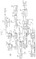
- a VLC decoder in accordance with a preferred embodiment of the present invention is shown in Fig. 1. It is assumed that the maximum length of the variable-length codeword to be decoded is 16 bits.
- the VLC decoder 100 decodes successive variable length codewords inputted to it in a continuous bit stream and outputs decoded fixed length codewords corresponding thereto, at a fixed symbol clock, on a lead 24; and comprises first and second latch circuits 10 and 20, first and second barrel shifters 30 and 40, and first and second memory devices 50 and 60.
- a serial data stream received on a data channel 24 is inputted to an input buffer memory 101 which stores, in fixed-length data segments, the serial data stream variable-length words and sequentially outputs fixed length data segments, e.g., 16-bit segments on a lead 11 in response to a READ signal on a lead 22, wherein the bit length of the data segment is identical to the maximum bit length of the variable length codeword.
- the first latch circuit 10 is connected to the input buffer memory 101 and serves to sequentially receive the fixed-length data segments in response to the READ signal on the lead 22.
- the second latch circuit 20 is connected to the first latch circuit 10 and functions to receive the fixed-length data segment previously held in the first latch circuit 10. When a new data segment needs to be supplied, a READ control signal is activated on the lead 22. In response thereto, the buffer memory 101 supplies the next data segment onto the lead 11; the first latch circuit 10 receives the next data segment; and the data segment previously held in the first circuit 10 is transferred to the second latch circuit 20.
- the second latch circuit 20 thus always contains the data segment which is sequentially earlier in time than the data segment contained in the first latch circuit 10.
- the two data segments contained in the first and the second latch circuits 10 and 20 comprise a 32-bit sequence of the serial input data to be decoded, which is twice the size of the maximum length codeword.
- the two data segments in the first and the second latch circuits 10 and 20 are inputted to the first barrel shifter 30 over parallel leads 12 and 13, respectively. That is, the bits in this new segment are concatenated with the bits in the previous segment and then transferred into the first barrel shifter 30.
- the output from the first barrel shifter 30 on a lead 14 is a 16-bit sequence of the two input data segments: the previous data segment outputted from the second latch circuit 20 and the current data segment outputted from the first latch circuit 10.
- the barrel shifter is directly shifted to place the next sequence of the two data segments.
- the current data segment in the first latch circuit 10 is inputted to the second latch circuit 20 as a previous data segment and the next 16-bit segment is read into the first latch circuit 10 from the input buffer memory 101 as a current data segment.
- the outputs of the first barrel shifter 30 are connected to the first memory device 50 and the second barrel shifter 40.
- the first memory device 50 is implemented by a programmable logic array(PLA).
- the PLA 50 shown in Fig. 1 is shown to comprise a codeword table AND plane 51, a word length table OR plane 52 and a decoded word table OR plane 53. As is also described in U.S. Pat. Nos.
- each codeword is represented as an entry in the codeword table AND plane 51 according to the bit pattern of the codeword. Since most codeword in a codeword library, which has the maximum word length of 16 bits, have fewer than 16 bits, the bit positions of the output from the barrel shifter, beyond the actual codeword bit pattern in the codeword table, are designated "don't care" positions.
- a codeword is detected when a sequence from the barrel shifter 30 matches one of the codeword bits patterns stored in the codeword table AND plane 51. Thus, for example, if one of the variable-length codeword bit patterns is "01”, and the 16-bit sequence from the barrel shifter 30 has a pattern "0111110000011101", then a match occurs on the first two bits. The first two bits are thus recognized as a variable-length codeword and the next word begins with the third bit.
- the entry in the word length table OR plane 52 and the entry in the decoded word table OR plane 53 are activated.
- the decoded word table OR plane 53 outputs onto a lead 21 through an output selection block 80 the decoded fixed length word corresponding to the matched variable length codeword in the codeword table AND plane 51.
- the word length table OR plane 52 produces a first word length signal on a lead 16 that indicates the length of the matched variable length codeword in the codeword table 51.
- the word length table 51 outputs "2", representing the length of the detected word "01".
- This word length, on a lead 16 is directly coupled to the barrel shifter 40 as a second window control signal.
- the word length is also inputted, on a lead 16, into an accumulator circuit 70 which accumulates the decoded word lengths and generates the first window control signal on the lead 23 used to control the first barrel shifter 30.
- the output from the first barrel shifter 30, i.e., the first decoding window output sequence, is inputted to the second barrel shifter 40 over a lead 14.
- the second barrel shifter 40 is substantially identical to the first barrel shifter 30 except that the current data segment is fixed as "0000000000000000" and the first decoding window output sequence is always supplied as a previous data segment.
- the second decoding window output sequence from the second barrel shifter 40 on a lead 15 is a 16-bit sequence shifted by the second window control signal which indicates the length of a previously matched variable length codeword in the first memory device 50.
- the second decoding window of the barrel shifter 40 is directly shifted to place the specific sequence beginning with the first bit of the next to-be-decoded variable length codeword in the first decoding window output sequence.
- the second decoding window output sequence is coupled to the second memory device 60.
- the second memory device 60 is substantially identical to the first memory device 50, but may include only a part of the codeword table which represents variable length coded transform coefficients.
- the second memory device is also implemented by a programmable logic array(PLA) and comprises a codeword table AND plane 61, a word length table OR plane 62 and a decoded word table OR plane 63. As is described above, when the second decoding window output sequence on the lead 15 matches an entry in the codeword table AND plane 61, the entry in the word length table OR plane 62 and the entry in the decoded word table OR plane 63 are activated.
- the decoded word table OR plane 63 outputs, on a lead 19, to an output selection block 80 the fixed length codeword corresponding to the matched variable length codeword in the codeword table AND plane 61.
- the fixed length codeword is outputted onto a lead 21 from the output selection block 80 in response to an output change signal outputted from a variable length decoding(VLD) control circuit 90.
- the word length table OR plane 62 produces an second word length signal on a lead 17 that indicates the length of the matched variable length codeword in the codeword table AND plane 60. This word length, on a lead 17, is inputted to the accumulator circuit 70.
- the accumulator 70 serves to add the first codeword length to the second codeword length to produce an added codeword length in response to an output change signal outputted from the VLD control circuit 90; and to sum the added codeword length with the previous accumulated modulo 16 word lengths to produce the first window control signal on a lead 23 in response to a clock signal outputted from the VLD control circuit 90.
- the first window control signal indicating the new accumulated codeword length is used to control the first barrel shifter 30. That is, in response to the clock signal, this first window control signal in the accumulator 70 is outputted on the lead 23 to the first barrel shifter 30 which shifts the position of the first decoding window to the next undecoded bits contained in the previous data segment of the first barrel shifter 30.
- the accumulator 70 activates a READ signal that indicates that all the bits in the previous data segment of the second latch circuit 30 have been decoded and can now be discarded.
- This READ signal of "1" is outputted on a lead 22 to the input buffer memory 101 and the first and the second latch circuits 10 and 20 in order to bring the next 16-bit segment in the input buffer memory 101 into the first latch circuit 10 while transferring the contents of the first latch circuit 10 to the second latch circuit 20.
- the first window control signal outputted from the accumulator 70 is activated after two variable length codewords contained in the previous data segment have been decoded; and the READ signal is activated only after all the bits in the previous data segment have been decoded which, depending the length of the decoded words, can be several clock cycles duration.
- Fig.1 The operation of the decoder in Fig.1 may be more readily understood with reference to an example shown in tabular form in Figs. 2 and 3. It is assumed that the data stream inputted from the data channel 24 to the input buffer memory 101 shown in Fig. 1 consists of the bit stream a1-a8b1-b6c1-c5d1-d5e1-e8f1-f7g1-g9h1-h6 Vietnamese, as shown in Fig. 2, wherein a1-a8 represents the eight bits in the first variable length codeword, b1-b6 represents the six bits in the second variable length codeword, etc.
- the first and the second latch circuits 10 and 20 are initialized. With the READ signal being "1", the first data segment, consisting of the 16 bits of a1-a8b1-b6c1c2, is inputted on a lead 11 to the first latch circuit 10. At this time, the outputs of the first and the second latch circuits 10 and 20, the outputs of the first and the second barrel shifters 30 and 40, and the outputs of the first and the second memory devices 50 and 60 are noise values, represented in Fig. 3 with an "X".
- a READ signal is "1" wherein a next data segment of c3-c5d1-d5e1-e8 is outputted from the input buffer memory 101 onto the lead 11.
- the data segment of a1-a8b1-b6c1c2 is latched in the first latch circuit 10.
- a READ signal is "1" and a next data segment of f1-f7g1-g9 is outputted from the input buffer memory 10.
- the data segment of c3-c5d1-d5e1-e8 is latched as a current data segment into the first latch circuit 10 and the data segment of a1-a8b1-b6c1c2 previously latched in the first latch circuit 10 is transferred as a previous data segment into the second latch circuit 20.
- the current and previous data segments are simultaneously coupled into the first barrel shifter 30 which transfers the previous data segment as the first decoding window output sequence on a lead 14 since the first window control signal is "0".
- the first memory device 50 recognizes the first eight bits in the first decoding window output sequence as decoded word "A" and outputs this fixed length decoded word, A, through the output selection block 80 onto the lead 21.
- the first memory device 50 also outputs the length, "8", of this word on a lead 16.
- the second window control signal indicating the previous decoded length, "8" is then coupled to the second barrel shifter 40 which transfers the 16-bit sequence of b1-b6c1c200000000 as the second decoding window output sequence into the second memory device 60.
- the second memory device 60 recognizes the first six bits in the second decoding window output sequence as decoded word "B" and outputs this fixed length decoded word, B, to the output selection block 80 which, in response to the output change signal, outputs the fixed length decoded word, B, onto the lead 21.
- the output change signal is activated from the VLD control circuit 90 after a predetermined time period from the second clock tick, wherein the predetermined time period encompasses the operational delays of the first barrel shifter 30 and the first and the second memory devices 50 and 60.
- the second memory device 50 also outputs the length, "6", of that decoded word on a lead 17.
- the accumulator 70 adds, in response to the output change signal on a lead 27, the previous decoded length, "8", on the lead 16 to the decoded length, "6", on the lead 17 in order to produce the first window control signal indicating a length, "14", wherein the previously accumulated modulo 16 word length is "0".
- the READ signal is "0".
- the first window control signal is coupled to the first barrel shifter 30 wherein the first decoding window is shifted to encompass the 15th bit in the previous data segment through the 30th in the current data segment. Therefore, the 16-bit sequence of c1-c5d1-d5e1-e6 is coupled to the first memory device 50 and the second barrel shifter 40.
- the first memory device 50 recognizes the first five bits in the previous data segment as decoded word "C” and outputs this fixed length decoded word, C, through the output selection block 80 onto the lead 21.
- the first memory device 50 also outputs the length, "5", of this word on the lead 16.
- the second window control signal indicating the previous decoded length, "5" is then coupled to the second barrel shifter 40 which transfers the 16-bit sequence of d1-d5e1-e600000 into the second memory device 60.
- the second memory device 60 recognizes the first five bits in the previous data segment as decoded word "D" and outputs this fixed length decoded word, D, to the output selection block 80 which, in response to the output change signal, outputs the fixed length decoded word, D, onto the lead 21.
- the second memory device 60 also outputs the length, "5", of this decoded word on a lead 17.
- the accumulator 70 adds the previous decoded length, "5", on the lead 16 to the decoded length, "5", on the lead 17 in response to the output change signal on a lead 26.
- the accumulator 70 also sums the added length of "10” with the previously accumulated modulo 16 codeword length "14" in order to produce the first window control signal indicating a length, "24", on a lead 23 in response to the clock signal on the lead 26.
- the READ signal is "1".
- the current and previous data segments are simultaneously coupled into the first barrel shifter which transfers the 16-bit sequence of e1-e8f1-f7g1, beginning with the 8th bit in the previous data segment, on a lead 14 since the first window control signal is "24(modulo 16 + 8)".
- the first memory device 50 recognizes the first eight bits in the previous data segment as decoded word "E” and outputs this fixed length decoded word, E, through the output selection block 80 onto the lead 21.
- the first memory device 50 also outputs the length, "8", of this word on the lead 16.
- the second window control signal indicating the previous decoded length, "8" is then coupled to the second barrel shifter 40 which transfers the 16-bit sequence of f1-f7g100000000 into the second memory device 60.
- the first memory device 60 recognizes the first seven bits in the previous data segment as decoded word "F" and outputs this fixed length decoded word, F, to the output selection block 80 which, in response to the output change signal, outputs the fixed length decoded word, B, onto the lead 21.
- the second memory device 50 also outputs the length, "7", of this decoded word on the lead 17.
- the VLC decoding apparatus of the present invention provides a further reduction of an operational delay in an accumulator, thereby advantageously achieving a high speed decoding operation.
Abstract
Description
- The present invention relates to a variable length code(VLC) decoding apparatus; and, more particularly, to an improved VLC decoding apparatus which is capable of providing a high speed decoding operation by effectively reducing the operational delay of an accumulator contained therein.
- Variable length coding is a technique often used for lossless data compression. This technique is used to convert fixed-length data to variable-length codewords based on the statistical occurrences of the data. The length of the codewords is chosen in such a manner that shorter codewords are used to represent more frequently occurring data and longer codewords are selected to represent less frequently occurring data. By properly assigning the variable-length codewords to a library of all possible source codewords, the average word length of the variable-length codewords becomes shorter than that of the original data, thereby rendering it possible to achieve data compression.
- In this connection, Huffman code design is a procedure commonly used to construct a minimum redundant variable length code for a known data statistic. In general, the encoding process can be implemented by using a table-lookup process using input data to address the table. The codewords and the word-length information are stored as contents of the table and outputted sequentially through the use of a buffer at a constant data rate onto the data channel.
- At the receiving end, however, the decoding process is more complicated. Owing to the variable length nature, each codeword has to be segmented from the received bit string before it can be decoded into a source symbol. Therefore, the design of a variable word length decoder is more difficult than that of a variable length encoder.
- There are several known apparatus for use to decode a stream of variable length codewords. Among them, most often used is a VLC decoder employing a tree-searching algorithm such as the one disclosed in U.S. Pat. No. 4,899,149 issued on Feb. 6, 1990 to Gary Kahan. In this device, a variable length code is represented by a tree with codewords as leaves(also called terminal nodes). The decoding process starts from the root of the code tree and is guided by the received bit stream to follow one of two branches at each node. When a leaf is reached, the end of a codeword is detected and is segmented from the remaining bit stream. This type of decoding apparatus includes a logic circuitry corresponding to the tree and a control circuitry to traverse the code tree. This approach may be slow, however, especially for long codewords, since a bit-by-bit search through the code tree is required for each decoded symbol.
- A lookup-table based VLC decoder is disclosed in U.S. Pat. No. 5,173,695 issued on December 22, 1992 to Ming-Ting Sun, et al.; and U.S. Pat. No. 5,245,338 to Ming-Ting Sun. That decoder includes two cascaded latch circuits, each having a bit capability equal to the maximum codeword length, which store consecutive bits supplied from an input buffer memory for storing the stream to be decoded in fixed-length data segments; a barrel shifter connected to the two latch circuits for providing a sliding decoding window output equal in length to the maximum codeword length; an accumulator which accumulates, modulo the maximum codeword length, the lengths of sequentially decoded variable length codewords; and a lookup-table memory device for outputting a fixed-length word corresponding to a variable-length codeword contained in the sliding decoding window output and for outputting a length of the variable-length codeword. As a codeword is decoded during each clock cycle, its length is accumulated and the decoding window of the barrel shifter is shifted to begin with the first bit of the next to-be-decoded codeword. When, during a clock cycle, the accumulated length exceeds the maximum codeword length, which would indicate that all the bits in the second latch circuit have been decoded, the bits in the first latch circuit are transferred into the second latch circuit and the next fixed-data segment of bits is read into the first latch circuit from the input buffer memory.
- In the afore-described decoder structure, the speed of operation is limited by the operational delay of the components in a critical path that includes the lookup-table memory, the barrel shifter, and the accumulator. It is the accumulator, which as are part of its functions, controls the reading operation of the input buffer memory into the second latch, that causes a substantial or significant portion of the total operational delay. This delay will have the deleterious effect for high-speed decoding required in, e.g., high definition television systems.
- It is, therefore, a primary object of the invention to provide a VLC decoding apparatus which employs two barrel shifters and two corresponding variable length decoding table memories to alternately reducing the operational delay in an accumulator, thereby advantageously achieving a high speed decoding operation.
- In accordance with the present invention, a variable length code decoding apparatus for decoding, at a fixed clock rate, sequential variable length codewords supplied from an input buffer which stores an input bit stream to be decoded in fixed length segments having the length equal to the longest length of the variable length codewords, comprises: first and second bit storage means, in response to a read signal, for storing consecutively two fixed length segments from the input buffer; first decoder shift means connected to the first and the second bit storage means and having a first decoding window for producing a first decoding window output sequence of the two fixed length segments, the bit length of the first decoding window output being equal to the longest length of the variable length codewords and said first decoding window being shifted in direct response to a window control signal; first memory means coupled to the first decoder shift means for producing a fixed length codeword in response to a variable length codeword that begins at the first bit position of the first decoding window output sequence and for producing a first codeword length output corresponding to the decoded variable length codeword; second decoder shift means connected to said first decoder shifter means and having a second decoding window for producing a second decoding window output sequence from bits contained in the first decoding window output sequence and a predetermined fixed length segment, the bit length of the second decoding window output being equal to the longest length of the variable length codewords and said decoding window being shifted in direct response to the first codeword length output so that the first bit position in the second decoding window output sequence is the first bit position of a next variable length codeword to be decoded in the first decoding window output sequence; second memory means for producing a fixed length codeword in response to said next variable length codeword and for producing a second codeword length output corresponding to the decoded next variable length codeword; and accumulator means for adding the first and the second codeword length outputs to produce an added codeword length output and for adding, at each clock, the added codeword length output to a previously accumulated codeword length output in order to produce the window control signal indicating the added and accumulated codeword length, said accumulator generating the read signal to retrieve a next fixed length segment stored in the input buffer when said added and accumulated codeword length is greater than the longest length of the variable length codewords, said next fixed length segment being stored in the first bit storage means and the fixed length segment previously stored in the first bit storage means being transferred to the second bit storage means.
- The above and other objects and features of the instant invention will become apparent from the following description of preferred embodiments taken in conjunction with the accompanying drawings, in which:
- Fig. 1 shows a schematic diagram of a VLC decoding apparatus in accordance with the present invention;
- Fig. 2 depicts the input bit stream used for explaining the operation for the VLC decoding apparatus shown in Fig. 1; and
- Fig. 3 provides an explanatory diagram for illustrating the operation of the VLC decoding apparatus shown in Fig. 1.
- A VLC decoder in accordance with a preferred embodiment of the present invention is shown in Fig. 1. It is assumed that the maximum length of the variable-length codeword to be decoded is 16 bits. The
VLC decoder 100 decodes successive variable length codewords inputted to it in a continuous bit stream and outputs decoded fixed length codewords corresponding thereto, at a fixed symbol clock, on alead 24; and comprises first andsecond latch circuits second barrel shifters second memory devices - A serial data stream received on a
data channel 24 is inputted to aninput buffer memory 101 which stores, in fixed-length data segments, the serial data stream variable-length words and sequentially outputs fixed length data segments, e.g., 16-bit segments on alead 11 in response to a READ signal on alead 22, wherein the bit length of the data segment is identical to the maximum bit length of the variable length codeword. - The
first latch circuit 10 is connected to theinput buffer memory 101 and serves to sequentially receive the fixed-length data segments in response to the READ signal on thelead 22. Thesecond latch circuit 20 is connected to thefirst latch circuit 10 and functions to receive the fixed-length data segment previously held in thefirst latch circuit 10. When a new data segment needs to be supplied, a READ control signal is activated on thelead 22. In response thereto, thebuffer memory 101 supplies the next data segment onto thelead 11; thefirst latch circuit 10 receives the next data segment; and the data segment previously held in thefirst circuit 10 is transferred to thesecond latch circuit 20. Thesecond latch circuit 20 thus always contains the data segment which is sequentially earlier in time than the data segment contained in thefirst latch circuit 10. The two data segments contained in the first and thesecond latch circuits - The two data segments in the first and the
second latch circuits first barrel shifter 30 over parallel leads 12 and 13, respectively. That is, the bits in this new segment are concatenated with the bits in the previous segment and then transferred into thefirst barrel shifter 30. The output from thefirst barrel shifter 30 on alead 14 is a 16-bit sequence of the two input data segments: the previous data segment outputted from thesecond latch circuit 20 and the current data segment outputted from thefirst latch circuit 10. As will be described below, when the first window control signal is activated on thelead 23, the barrel shifter is directly shifted to place the next sequence of the two data segments. When a shift greater than fifteen occurs, indicating that all bits in the previous data segment have been decoded, the current data segment in thefirst latch circuit 10 is inputted to thesecond latch circuit 20 as a previous data segment and the next 16-bit segment is read into thefirst latch circuit 10 from theinput buffer memory 101 as a current data segment. The outputs of thefirst barrel shifter 30 are connected to thefirst memory device 50 and thesecond barrel shifter 40. In the described embodiment, thefirst memory device 50 is implemented by a programmable logic array(PLA). ThePLA 50 shown in Fig. 1 is shown to comprise a codeword table AND plane 51, a word length table ORplane 52 and a decoded word table ORplane 53. As is also described in U.S. Pat. Nos. 5,267,266 and 5,173,695, each codeword is represented as an entry in the codeword table AND plane 51 according to the bit pattern of the codeword. Since most codeword in a codeword library, which has the maximum word length of 16 bits, have fewer than 16 bits, the bit positions of the output from the barrel shifter, beyond the actual codeword bit pattern in the codeword table, are designated "don't care" positions. A codeword is detected when a sequence from thebarrel shifter 30 matches one of the codeword bits patterns stored in the codeword table AND plane 51. Thus, for example, if one of the variable-length codeword bit patterns is "01", and the 16-bit sequence from thebarrel shifter 30 has a pattern "0111110000011101", then a match occurs on the first two bits. The first two bits are thus recognized as a variable-length codeword and the next word begins with the third bit. - When the first decoding window output sequence on the
lead 14 matches an entry in the codeword table AND plane 51, the entry in the word length table ORplane 52 and the entry in the decoded word table ORplane 53 are activated. The decoded word table ORplane 53 outputs onto alead 21 through anoutput selection block 80 the decoded fixed length word corresponding to the matched variable length codeword in the codeword table AND plane 51. - The word length table OR
plane 52 produces a first word length signal on a lead 16 that indicates the length of the matched variable length codeword in the codeword table 51. For the example above, the word length table 51 outputs "2", representing the length of the detected word "01". This word length, on alead 16, is directly coupled to thebarrel shifter 40 as a second window control signal. The word length is also inputted, on alead 16, into anaccumulator circuit 70 which accumulates the decoded word lengths and generates the first window control signal on thelead 23 used to control thefirst barrel shifter 30. - As is described above, the output from the
first barrel shifter 30, i.e., the first decoding window output sequence, is inputted to thesecond barrel shifter 40 over alead 14. Thesecond barrel shifter 40 is substantially identical to thefirst barrel shifter 30 except that the current data segment is fixed as "0000000000000000" and the first decoding window output sequence is always supplied as a previous data segment. The second decoding window output sequence from thesecond barrel shifter 40 on alead 15 is a 16-bit sequence shifted by the second window control signal which indicates the length of a previously matched variable length codeword in thefirst memory device 50. As is described, when the second window control signal is activated on thelead 16, the second decoding window of thebarrel shifter 40 is directly shifted to place the specific sequence beginning with the first bit of the next to-be-decoded variable length codeword in the first decoding window output sequence. - The second decoding window output sequence is coupled to the
second memory device 60. In accordance with a preferred embodiment, thesecond memory device 60 is substantially identical to thefirst memory device 50, but may include only a part of the codeword table which represents variable length coded transform coefficients. The second memory device is also implemented by a programmable logic array(PLA) and comprises a codeword table ANDplane 61, a word length table ORplane 62 and a decoded word table ORplane 63. As is described above, when the second decoding window output sequence on the lead 15 matches an entry in the codeword table ANDplane 61, the entry in the word length table ORplane 62 and the entry in the decoded word table ORplane 63 are activated. The decoded word table ORplane 63 outputs, on alead 19, to anoutput selection block 80 the fixed length codeword corresponding to the matched variable length codeword in the codeword table ANDplane 61. The fixed length codeword is outputted onto a lead 21 from theoutput selection block 80 in response to an output change signal outputted from a variable length decoding(VLD)control circuit 90. The word length table ORplane 62 produces an second word length signal on a lead 17 that indicates the length of the matched variable length codeword in the codeword table ANDplane 60. This word length, on alead 17, is inputted to theaccumulator circuit 70. - The
accumulator 70 serves to add the first codeword length to the second codeword length to produce an added codeword length in response to an output change signal outputted from theVLD control circuit 90; and to sum the added codeword length with the previous accumulated modulo 16 word lengths to produce the first window control signal on a lead 23 in response to a clock signal outputted from theVLD control circuit 90. The first window control signal indicating the new accumulated codeword length is used to control thefirst barrel shifter 30. That is, in response to the clock signal, this first window control signal in theaccumulator 70 is outputted on thelead 23 to thefirst barrel shifter 30 which shifts the position of the first decoding window to the next undecoded bits contained in the previous data segment of thefirst barrel shifter 30. - When the new accumulated sum exceeds 15, the
accumulator 70 activates a READ signal that indicates that all the bits in the previous data segment of thesecond latch circuit 30 have been decoded and can now be discarded. This READ signal of "1" is outputted on a lead 22 to theinput buffer memory 101 and the first and thesecond latch circuits input buffer memory 101 into thefirst latch circuit 10 while transferring the contents of thefirst latch circuit 10 to thesecond latch circuit 20. - It can be seen, therefore, that the first window control signal outputted from the
accumulator 70 is activated after two variable length codewords contained in the previous data segment have been decoded; and the READ signal is activated only after all the bits in the previous data segment have been decoded which, depending the length of the decoded words, can be several clock cycles duration. - The operation of the decoder in Fig.1 may be more readily understood with reference to an example shown in tabular form in Figs. 2 and 3. It is assumed that the data stream inputted from the
data channel 24 to theinput buffer memory 101 shown in Fig. 1 consists of the bit stream a1-a8b1-b6c1-c5d1-d5e1-e8f1-f7g1-g9h1-h6....., as shown in Fig. 2, wherein a1-a8 represents the eight bits in the first variable length codeword, b1-b6 represents the six bits in the second variable length codeword, etc. - Referring to Fig. 3, prior to the first clock tick, the first and the
second latch circuits first latch circuit 10. At this time, the outputs of the first and thesecond latch circuits second barrel shifters second memory devices - At the first clock tick, a READ signal is "1" wherein a next data segment of c3-c5d1-d5e1-e8 is outputted from the
input buffer memory 101 onto thelead 11. At this READ signal, the data segment of a1-a8b1-b6c1c2 is latched in thefirst latch circuit 10. - At the second clock tick, a READ signal is "1" and a next data segment of f1-f7g1-g9 is outputted from the
input buffer memory 10. At this READ signal, the data segment of c3-c5d1-d5e1-e8 is latched as a current data segment into thefirst latch circuit 10 and the data segment of a1-a8b1-b6c1c2 previously latched in thefirst latch circuit 10 is transferred as a previous data segment into thesecond latch circuit 20. The current and previous data segments are simultaneously coupled into thefirst barrel shifter 30 which transfers the previous data segment as the first decoding window output sequence on a lead 14 since the first window control signal is "0". Thefirst memory device 50 recognizes the first eight bits in the first decoding window output sequence as decoded word "A" and outputs this fixed length decoded word, A, through theoutput selection block 80 onto thelead 21. Thefirst memory device 50 also outputs the length, "8", of this word on alead 16. The second window control signal indicating the previous decoded length, "8", is then coupled to thesecond barrel shifter 40 which transfers the 16-bit sequence of b1-b6c1c200000000 as the second decoding window output sequence into thesecond memory device 60. Thesecond memory device 60 recognizes the first six bits in the second decoding window output sequence as decoded word "B" and outputs this fixed length decoded word, B, to theoutput selection block 80 which, in response to the output change signal, outputs the fixed length decoded word, B, onto thelead 21. The output change signal is activated from theVLD control circuit 90 after a predetermined time period from the second clock tick, wherein the predetermined time period encompasses the operational delays of thefirst barrel shifter 30 and the first and thesecond memory devices second memory device 50 also outputs the length, "6", of that decoded word on alead 17. Theaccumulator 70 adds, in response to the output change signal on a lead 27, the previous decoded length, "8", on thelead 16 to the decoded length, "6", on thelead 17 in order to produce the first window control signal indicating a length, "14", wherein the previously accumulated modulo 16 word length is "0". - At the third clock tick, since the accumulated codeword length is less than "16", the READ signal is "0". The first window control signal is coupled to the
first barrel shifter 30 wherein the first decoding window is shifted to encompass the 15th bit in the previous data segment through the 30th in the current data segment. Therefore, the 16-bit sequence of c1-c5d1-d5e1-e6 is coupled to thefirst memory device 50 and thesecond barrel shifter 40. Thefirst memory device 50 recognizes the first five bits in the previous data segment as decoded word "C" and outputs this fixed length decoded word, C, through theoutput selection block 80 onto thelead 21. Thefirst memory device 50 also outputs the length, "5", of this word on thelead 16. The second window control signal indicating the previous decoded length, "5", is then coupled to thesecond barrel shifter 40 which transfers the 16-bit sequence of d1-d5e1-e600000 into thesecond memory device 60. Thesecond memory device 60 recognizes the first five bits in the previous data segment as decoded word "D" and outputs this fixed length decoded word, D, to theoutput selection block 80 which, in response to the output change signal, outputs the fixed length decoded word, D, onto thelead 21. Thesecond memory device 60 also outputs the length, "5", of this decoded word on alead 17. Theaccumulator 70 adds the previous decoded length, "5", on thelead 16 to the decoded length, "5", on thelead 17 in response to the output change signal on alead 26. Theaccumulator 70 also sums the added length of "10" with the previously accumulated modulo 16 codeword length "14" in order to produce the first window control signal indicating a length, "24", on a lead 23 in response to the clock signal on thelead 26. - At the fourth clock tick, since the accumulated codeword length is greater than "16", the READ signal is "1". At this READ signal, a next data segment of h1-h6....... is retrieved from the input
buffer memory device 101; the data segment of f1-f7g1-g9 is latched as a current data segment into thefirst latch circuit 10; and the data segment of c3-c5d1-d5e1-e8 previously latched in thefirst latch circuit 10 is transferred as a previous data segment into thesecond latch circuit 20. The current and previous data segments are simultaneously coupled into the first barrel shifter which transfers the 16-bit sequence of e1-e8f1-f7g1, beginning with the 8th bit in the previous data segment, on a lead 14 since the first window control signal is "24(modulo 16 + 8)". Thefirst memory device 50 recognizes the first eight bits in the previous data segment as decoded word "E" and outputs this fixed length decoded word, E, through theoutput selection block 80 onto thelead 21. Thefirst memory device 50 also outputs the length, "8", of this word on thelead 16. The second window control signal indicating the previous decoded length, "8", is then coupled to thesecond barrel shifter 40 which transfers the 16-bit sequence of f1-f7g100000000 into thesecond memory device 60. Thefirst memory device 60 recognizes the first seven bits in the previous data segment as decoded word "F" and outputs this fixed length decoded word, F, to theoutput selection block 80 which, in response to the output change signal, outputs the fixed length decoded word, B, onto thelead 21. Thesecond memory device 50 also outputs the length, "7", of this decoded word on thelead 17. - As may be seen from the above, it should be readily appreciated that, since the second barrel shifter is cascaded to the first barrel shifter and provides a second table memory device with a decoding window output sequence which is, independent of the accumulator, directly shifted in response to a codeword length output from a first table memory device, the VLC decoding apparatus of the present invention provides a further reduction of an operational delay in an accumulator, thereby advantageously achieving a high speed decoding operation.
- While the present invention has been shown and described in connection with the preferred embodiments only, it will be readily apparent to those of ordinary skill in the art that many changes and modifications may be made without departing from the spirit and scope of the invention as defined in the appended claim.
Claims (1)
- A variable length code decoding apparatus for decoding, at a fixed clock rate, sequential variable length codewords supplied from an input buffer which stores an input bit stream to be decoded in fixed length segments having the length equal to the longest length of the variable length codewords, said apparatus comprising:
first and second bit storage means, in response to a read signal, for storing consecutively two fixed length segments from the input buffer;
first decoder shift means connected to the first and the second bit storage means and having a first decoding window for producing a first decoding window output sequence of the two fixed length segments, the bit length of the first decoding window output being equal to the longest length of the variable length codewords and said first decoding window being shifted in direct response to a window control signal;
first memory means coupled to the first decoder shift means for producing a fixed length codeword in response to a variable length codeword that begins at the first bit position of the first decoding window output sequence and for producing a first codeword length output corresponding to the decoded variable length codeword;
second decoder shift means connected to said first decoder shifter means and having a second decoding window for producing a second decoding window output sequence from bits contained in the first decoding window output sequence and a predetermined fixed length segment, the bit length of the second decoding window output being equal to the longest length of the variable length codewords and said decoding window being shifted in direct response to the first codeword length output so that the first bit position in the second decoding window output sequence is the first bit position of a next variable length codeword to be decoded in the first decoding window output sequence;
second memory means for producing a fixed length codeword in response to said next variable length codeword and for producing a second codeword length output corresponding to the decoded next variable length codeword; and
accumulator means for adding the first and the second codeword length outputs to produce an added codeword length output and for adding, at each clock, the added codeword length output to a previously accumulated codeword length output in order to produce the window control signal indicating the added and accumulated codeword length, said accumulator generating the read signal to retrieve a next fixed length segment stored in the input buffer when said added and accumulated codeword length is greater than the longest length of the variable length codewords, said next fixed length segment being stored in the first bit storage means and the fixed length segment previously stored in the first bit storage means being transferred to the second bit storage means.
Applications Claiming Priority (2)
| Application Number | Priority Date | Filing Date | Title |
|---|---|---|---|
| KR9325675 | 1993-11-29 | ||
| KR1019930025675A KR970002483B1 (en) | 1993-11-29 | 1993-11-29 | A high speed variable length decoder |
Publications (2)
| Publication Number | Publication Date |
|---|---|
| EP0655842A2 true EP0655842A2 (en) | 1995-05-31 |
| EP0655842A3 EP0655842A3 (en) | 1997-01-22 |
Family
ID=19369243
Family Applications (1)
| Application Number | Title | Priority Date | Filing Date |
|---|---|---|---|
| EP94118771A Ceased EP0655842A3 (en) | 1993-11-29 | 1994-11-29 | High speed variable length code decoding apparatus. |
Country Status (5)
| Country | Link |
|---|---|
| US (1) | US5561690A (en) |
| EP (1) | EP0655842A3 (en) |
| JP (1) | JP3294026B2 (en) |
| KR (1) | KR970002483B1 (en) |
| CN (1) | CN1039469C (en) |
Cited By (4)
| Publication number | Priority date | Publication date | Assignee | Title |
|---|---|---|---|---|
| WO1997024810A1 (en) * | 1995-12-28 | 1997-07-10 | Philips Electronics N.V. | Variable length decoder |
| WO1997024811A1 (en) * | 1995-12-28 | 1997-07-10 | Philips Electronics N.V. | Variable length decoder |
| EP0862275A2 (en) * | 1997-02-27 | 1998-09-02 | Siemens Aktiengesellschaft | Decoder for variable length codes |
| US6215424B1 (en) * | 1998-12-16 | 2001-04-10 | Thomson Licensing S.A. | System for variable length codeword processing suitable for video and other applications |
Families Citing this family (22)
| Publication number | Priority date | Publication date | Assignee | Title |
|---|---|---|---|---|
| KR0152038B1 (en) * | 1994-10-17 | 1998-10-15 | 김광호 | Variable length decode apparatus using partner address |
| KR0154010B1 (en) * | 1995-03-16 | 1998-11-16 | 배순훈 | Variable length decoder |
| KR0180169B1 (en) * | 1995-06-30 | 1999-05-01 | 배순훈 | A variable length coder |
| KR0178201B1 (en) * | 1995-08-31 | 1999-05-01 | 배순훈 | Variable length decoding apparatus |
| KR100203246B1 (en) * | 1995-10-19 | 1999-06-15 | 윤종용 | The high speed variable length decoding apparatus |
| US5657016A (en) * | 1995-12-28 | 1997-08-12 | Philips Electronics North America Corporation | Variable length decoder with one of N length indicator |
| US5835035A (en) * | 1995-12-28 | 1998-11-10 | Philips Electronics North America Corporation | High performance variable length decoder with two-word bit stream segmentation and related method |
| US5696507A (en) * | 1996-05-31 | 1997-12-09 | Daewoo Electronics Co., Inc. | Method and apparatus for decoding variable length code |
| CN1098565C (en) * | 1996-06-07 | 2003-01-08 | 大宇电子株式会社 | Method and apparatus for decoding variable length code |
| US6195674B1 (en) * | 1997-04-30 | 2001-02-27 | Canon Kabushiki Kaisha | Fast DCT apparatus |
| KR100292050B1 (en) * | 1997-11-08 | 2001-06-01 | 김영환 | Data simulator of variable length decoder |
| JP4559652B2 (en) * | 2000-03-24 | 2010-10-13 | パナソニック株式会社 | Variable length decoding circuit |
| US6883047B2 (en) * | 2001-05-25 | 2005-04-19 | Intel Corporation | Concurrent asynchronous USB data stream destuffer with variable width bit-wise memory controller |
| US6653955B1 (en) | 2002-05-09 | 2003-11-25 | Lsi Logic Corporation | Multi-symbol variable length code decoder |
| US6674376B1 (en) * | 2002-09-13 | 2004-01-06 | Morpho Technologies | Programmable variable length decoder circuit and method |
| CN100356793C (en) * | 2005-06-09 | 2007-12-19 | 清华大学 | High-speed changeable long code parallel decoder |
| KR100946875B1 (en) * | 2006-12-21 | 2010-03-09 | 삼성전자주식회사 | Apparatus and method for transmitting/receiving data in a communication system |
| JP4703730B2 (en) * | 2007-01-19 | 2011-06-15 | 三菱電機株式会社 | Table device, variable length coding device, variable length decoding device, and variable length coding and decoding device |
| JP4841496B2 (en) * | 2007-04-26 | 2011-12-21 | パナソニック株式会社 | Variable length code decoding apparatus |
| WO2009122675A1 (en) * | 2008-03-31 | 2009-10-08 | パナソニック株式会社 | Variable length code decoding apparatus and method |
| CN103337253B (en) * | 2013-05-29 | 2016-02-03 | 北京大学 | A kind of cascade system of RRAM logical device and method |
| CN112737905B (en) * | 2020-12-22 | 2022-05-24 | 青岛鼎信通讯消防安全有限公司 | Method and system for transmitting and receiving parallel two-bus communication |
Citations (2)
| Publication number | Priority date | Publication date | Assignee | Title |
|---|---|---|---|---|
| US5173695A (en) * | 1990-06-29 | 1992-12-22 | Bell Communications Research, Inc. | High-speed flexible variable-length-code decoder |
| US5245338A (en) * | 1992-06-04 | 1993-09-14 | Bell Communications Research, Inc. | High-speed variable-length decoder |
Family Cites Families (3)
| Publication number | Priority date | Publication date | Assignee | Title |
|---|---|---|---|---|
| GB2270603B (en) * | 1992-09-09 | 1996-07-24 | Sony Broadcast & Communication | Data formatting |
| US5343195A (en) * | 1992-12-18 | 1994-08-30 | Thomson Consumer Electronics, Inc. | Variable length codeword decoding apparatus |
| US5400075A (en) * | 1993-01-13 | 1995-03-21 | Thomson Consumer Electronics, Inc. | Adaptive variable length encoder/decoder |
-
1993
- 1993-11-29 KR KR1019930025675A patent/KR970002483B1/en not_active IP Right Cessation
-
1994
- 1994-11-29 JP JP29476394A patent/JP3294026B2/en not_active Expired - Lifetime
- 1994-11-29 EP EP94118771A patent/EP0655842A3/en not_active Ceased
- 1994-11-29 US US08/346,067 patent/US5561690A/en not_active Expired - Lifetime
- 1994-11-29 CN CN94112762A patent/CN1039469C/en not_active Expired - Lifetime
Patent Citations (2)
| Publication number | Priority date | Publication date | Assignee | Title |
|---|---|---|---|---|
| US5173695A (en) * | 1990-06-29 | 1992-12-22 | Bell Communications Research, Inc. | High-speed flexible variable-length-code decoder |
| US5245338A (en) * | 1992-06-04 | 1993-09-14 | Bell Communications Research, Inc. | High-speed variable-length decoder |
Non-Patent Citations (1)
| Title |
|---|
| IEEE TRANSACTIONS ON CIRCUITS AND SYSTEMS FOR VIDEO TECHNOLOGY, vol. 2, no. 2, 1 June 1992, NEW YORK,US, pages 187-196, XP000280658 S. CHANG ET. AL.: "DESIGNING HIGH THROUGHPUT VLC DECODER PART 1" * |
Cited By (5)
| Publication number | Priority date | Publication date | Assignee | Title |
|---|---|---|---|---|
| WO1997024810A1 (en) * | 1995-12-28 | 1997-07-10 | Philips Electronics N.V. | Variable length decoder |
| WO1997024811A1 (en) * | 1995-12-28 | 1997-07-10 | Philips Electronics N.V. | Variable length decoder |
| EP0862275A2 (en) * | 1997-02-27 | 1998-09-02 | Siemens Aktiengesellschaft | Decoder for variable length codes |
| EP0862275A3 (en) * | 1997-02-27 | 1999-08-11 | Siemens Aktiengesellschaft | Decoder for variable length codes |
| US6215424B1 (en) * | 1998-12-16 | 2001-04-10 | Thomson Licensing S.A. | System for variable length codeword processing suitable for video and other applications |
Also Published As
| Publication number | Publication date |
|---|---|
| US5561690A (en) | 1996-10-01 |
| CN1039469C (en) | 1998-08-05 |
| CN1108019A (en) | 1995-09-06 |
| JP3294026B2 (en) | 2002-06-17 |
| KR970002483B1 (en) | 1997-03-05 |
| EP0655842A3 (en) | 1997-01-22 |
| JPH088755A (en) | 1996-01-12 |
| KR950016368A (en) | 1995-06-17 |
Similar Documents
| Publication | Publication Date | Title |
|---|---|---|
| US5561690A (en) | High speed variable length code decoding apparatus | |
| US5245338A (en) | High-speed variable-length decoder | |
| US5436626A (en) | Variable-length codeword encoder | |
| US5173695A (en) | High-speed flexible variable-length-code decoder | |
| US5055841A (en) | High-speed feedforward variable word length decoder | |
| JP3136796B2 (en) | Variable length code decoder | |
| US5696507A (en) | Method and apparatus for decoding variable length code | |
| Núñez et al. | Gbit/s lossless data compression hardware | |
| US5650781A (en) | Apparatus for decoding variable length codes | |
| US5901177A (en) | High speed variable length code decoding apparatus and method | |
| KR100527891B1 (en) | Method of performing huffman decoding | |
| US5818368A (en) | Method and apparatus for lossless digital data compression | |
| US5394144A (en) | Variable length code decoding apparatus | |
| US5677690A (en) | High speed variable length code decoding apparatus | |
| US5663726A (en) | High speed variable-length decoder arrangement with reduced memory requirements for tag stream buffering | |
| JP3032134B2 (en) | Variable length decoder for video signals | |
| US5648775A (en) | High speed variable length code decoding apparatus | |
| US5736946A (en) | High speed apparatus and method for decoding variable length code | |
| US5432512A (en) | Apparatus for decoding variable length codes | |
| US5708430A (en) | High speed variable length code decoding apparatus | |
| US5701126A (en) | High speed variable length decoder | |
| JP3389389B2 (en) | Variable length code decoding device | |
| JP2537551B2 (en) | Variable length code decoding circuit | |
| JP3229690B2 (en) | Variable length code decoder | |
| KR0125126B1 (en) | High-speed apparatus for decoding variable length code |
Legal Events
| Date | Code | Title | Description |
|---|---|---|---|
| PUAI | Public reference made under article 153(3) epc to a published international application that has entered the european phase |
Free format text: ORIGINAL CODE: 0009012 |
|
| AK | Designated contracting states |
Kind code of ref document: A2 Designated state(s): DE FR GB NL |
|
| PUAL | Search report despatched |
Free format text: ORIGINAL CODE: 0009013 |
|
| AK | Designated contracting states |
Kind code of ref document: A3 Designated state(s): DE FR GB NL |
|
| 17P | Request for examination filed |
Effective date: 19970722 |
|
| GRAG | Despatch of communication of intention to grant |
Free format text: ORIGINAL CODE: EPIDOS AGRA |
|
| 17Q | First examination report despatched |
Effective date: 19990716 |
|
| STAA | Information on the status of an ep patent application or granted ep patent |
Free format text: STATUS: THE APPLICATION HAS BEEN REFUSED |
|
| 18R | Application refused |
Effective date: 20000107 |