EP0656193B1 - Multipurpose surgical tool - Google Patents
Multipurpose surgical tool Download PDFInfo
- Publication number
- EP0656193B1 EP0656193B1 EP95102423A EP95102423A EP0656193B1 EP 0656193 B1 EP0656193 B1 EP 0656193B1 EP 95102423 A EP95102423 A EP 95102423A EP 95102423 A EP95102423 A EP 95102423A EP 0656193 B1 EP0656193 B1 EP 0656193B1
- Authority
- EP
- European Patent Office
- Prior art keywords
- aperture
- leaves
- tool
- bridge
- collet
- Prior art date
- Legal status (The legal status is an assumption and is not a legal conclusion. Google has not performed a legal analysis and makes no representation as to the accuracy of the status listed.)
- Expired - Lifetime
Links
Images
Classifications
-
- A—HUMAN NECESSITIES
- A61—MEDICAL OR VETERINARY SCIENCE; HYGIENE
- A61B—DIAGNOSIS; SURGERY; IDENTIFICATION
- A61B17/00—Surgical instruments, devices or methods, e.g. tourniquets
- A61B17/30—Surgical pincettes without pivotal connections
-
- A—HUMAN NECESSITIES
- A61—MEDICAL OR VETERINARY SCIENCE; HYGIENE
- A61B—DIAGNOSIS; SURGERY; IDENTIFICATION
- A61B17/00—Surgical instruments, devices or methods, e.g. tourniquets
- A61B17/32—Surgical cutting instruments
Definitions
- This invention relates generally to the field of surgery and more particularly to a hand tool capable of performing cutting, clamping, or shearing functions in surgical operations.
- Forceps and tweezers typically have a pair of handles interconnected by a pivot or flexible connection at a point along their length, so that squeezing the handles together produces relative jaw movement.
- the handles usually are substantially rigid, as in U.S. Patent 4,693,246; however, thin-section handles designed to flex when pressure is applied, in order to move the jaws, have been proposed also, as in U.S. Patents 4,212,305, No. 3,805,792, No. 1,615,125, No. 3,827,277 and No. 3,774,438.
- a further object of the invention is to provide a lightweight tool capable of performing cutting, clamping or shearing functions, depending upon the shape of the jaws.
- One further object is to assist a surgeon in regulating the degree of closure of jaws of such a tool by providing tactile feedback in the form of increasing resistance to the hand as a function of jaw closure.
- the invention is embodied in a tool in accordance with claim 1 below.
- a body portion including a pair of flexible leaves joined at their forward ends by a bridge having an aperture therein, and joined face-to-face at their rearward ends.
- An elongated collet extending perpendicularly between the leaves of the body is retained between the leaves at its rearward end.
- the leaves normally bowed outward from one another, can be squeezed toward one another, so as to lengthen the body and produce relative movement between the bridge and the forward end of the collet.
- a pair of tines at the forward end of the collet have inwardly facing working edges or jaws and outwardly facing oblique cam surfaces which interact with opposite sides of the aperture, to close the jaws, when the bridge portion of the body is driven toward the jaws by squeezing the leaves.
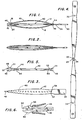
- a surgical tool embodying the invention shown in Figures 1-3, comprises only two parts -- a body portion 10 and a collet 40, both constructed from a resilient sheet metal such as stainless steel.
- the gauge of the material is chosen so as to provide sufficient flexibility that plastic deformation of the tool does not occur in normal use (hence the term “resiliently flexible” hereafter), and to provide the desired spring rate, according to the intended use of the tool.
- the body portion 10 includes a pair of identical leaves 12, 14 extending from opposite sides of a bight or bridge 16 defined by folding the blank on lines 18, 20.
- the bridge has a preformed aperture 22 at its center (see the body layout or blank, before folding, in Figure 4).
- the aperture is symmetrical about the center plane P of the tool, and has the form of an elongated slot with widened portions 24 at the center plane.
- the tabs 26, 28 at the ends of the blank are drawn together - - the resilience of the leaves resulting in an outwardly bowed configuration as shown -- and are welded or otherwise joined together to form a handle 30.
- the handle end of the tool is referred to as the "rearward" end of the tool hereafter.
- Aligned holes 32, 34 extend through the leaves near the tab juncture 36.
- the collet 40 shown in detail in Figure 5, comprises an elongate bar 42 which is bifurcated at both ends to form resiliently flexible forward tines 44, 46 and rearward tines 58, 60.
- Each of the forward tines has a jaw 48 at the distal end thereof.
- Each jaw ( Figure 6) has an inner working face or edge 50 and an outer edge, a portion of which obliquely angled so as to define a cam surface 52.
- the cam surfaces are preferably planar, and if extended would meet at the center plane of the tools, subtending an acute angle alpha as shown.
- the tines 44, 46 are resiliently flexible, so that the jaws can be deflected inwardly to the point where their working edges 50 meet (Figure 2), and then return to their original open position when released ( Figure 1).
- the tines, jaws and aperture are designed so that the tines are slightly flexed even in the relaxed position of the tool, whereby the cam surfaces are always in contact with the sides of the aperture.
- the collet 40 is permanently retained between the leaves of the body by tabs 54, 56 which extend outward from the ends of rearward tines 58, 60.
- the tines 58, 60 are deflected inward from their free position, so as to maintain a constant outward bias on the tabs 54, 56, and thus eliminate any free motion of the collet.
- the collet is aligned, by the aperture and by the holes 32, 34, so that a plane containing the four tines is perpendicular to and bisects each of the leaves. That is, the width of the collet is perpendicular to the leaves.
- tabs 54, 56, tines 58, 60 and holes 32, 34 are preferred because it provides for easy tool assembly and disassembly.
- the rearward end of the collet may be affixed between the leaves 12, 14, by other means, as long as such means perform the function of preventing substantial relative movement between the rearward ends of the parts.
- both of the tool components can be stamped from sheet metal, their manufacture is very straightforward and inexpensive; in addition, it is a simple matter to snap the two parts of the tool together.
- the tool is easily and thoroughly cleaned and sterilized, having no pivot points or recesses to harbor contaminants.
Abstract
Description
Claims (8)
- A tool comprising:a body portion (10) comprising a pair of resiliently flexible opposed leaves (12,14) joined at their forward ends by a bridge (16) having an elongate aperture (22) therein, said leaves also being joined face-to face at their rearward ends, and being normally bowed outward from one another; andan elongated collet (40) having a rearward end affixed to the rearward ends of said leaves, and a bifurcated forward end comprising a pair of resiliently flexible tines (44,46), each tine having thereon a jaw (48) protruding through said aperture, each jaw including an inwardly facing working surface (50) and an outwardly facing oblique cam surface in a position to engage a side of said aperture, so that relative longitudinal movement between the bridge and the jaws, produced by squeezing the leaves together, causes interaction between the sides of the aperture and the cam surfaces to drive the jaws together
characterised in that:the tines of the collet lie in a common plane perpendicular to and bisecting both of said leaves, the length of the aperture being aligned with said plane; and in thatthe two opposed leaves and the bridge are within a blank of resilient sheet material, the aperture being formed within the sheet. - A tool as claimed in claim 1 wherein the blank is a sheet metal blank having the aperture (22) preformed therein, with a bend in the blank on either side of the aperture to define said bridge (16).
- A tool as claimed in claim 1 or 2, wherein said aperture (22) has the form of a slot, widened at its center.
- A tool as claimed in claim 1, 2 or 3 wherein the bridge (16) is substantially perpendicular to the leaves (12, 14).
- A tool as claimed in any one of the preceding claims wherein the body portion (10) and collet (40) are both made of stainless steel.
- A tool as claimed in any one of the preceding claims and including a centre plane (P) about which the aperture (22) is symmetrical.
- A tool as claimed in any one of the preceding claims wherein the rearward ends joined together provide a handle for the tool.
- A tool as claimed in any one of the preceding claims, in which the collet (40) is a resilient snap fit within the body portion, to enable disassembly of the collet and body portion.
Applications Claiming Priority (3)
| Application Number | Priority Date | Filing Date | Title |
|---|---|---|---|
| US479567 | 1990-02-14 | ||
| US07/479,567 US5089007A (en) | 1990-02-14 | 1990-02-14 | Multipurpose surgical tool |
| EP91905191A EP0515545B1 (en) | 1990-02-14 | 1991-02-12 | Multipurpose surgical tool |
Related Parent Applications (2)
| Application Number | Title | Priority Date | Filing Date |
|---|---|---|---|
| EP91905191A Division EP0515545B1 (en) | 1990-02-14 | 1991-02-12 | Multipurpose surgical tool |
| EP91905191.2 Division | 1991-02-12 |
Publications (3)
| Publication Number | Publication Date |
|---|---|
| EP0656193A2 EP0656193A2 (en) | 1995-06-07 |
| EP0656193A3 EP0656193A3 (en) | 1995-08-30 |
| EP0656193B1 true EP0656193B1 (en) | 1998-08-19 |
Family
ID=23904550
Family Applications (2)
| Application Number | Title | Priority Date | Filing Date |
|---|---|---|---|
| EP91905191A Expired - Lifetime EP0515545B1 (en) | 1990-02-14 | 1991-02-12 | Multipurpose surgical tool |
| EP95102423A Expired - Lifetime EP0656193B1 (en) | 1990-02-14 | 1991-02-12 | Multipurpose surgical tool |
Family Applications Before (1)
| Application Number | Title | Priority Date | Filing Date |
|---|---|---|---|
| EP91905191A Expired - Lifetime EP0515545B1 (en) | 1990-02-14 | 1991-02-12 | Multipurpose surgical tool |
Country Status (9)
| Country | Link |
|---|---|
| US (1) | US5089007A (en) |
| EP (2) | EP0515545B1 (en) |
| JP (1) | JPH05506378A (en) |
| AT (2) | ATE129876T1 (en) |
| DE (2) | DE69114481T2 (en) |
| DK (2) | DK0515545T3 (en) |
| ES (2) | ES2079644T3 (en) |
| GR (1) | GR3018039T3 (en) |
| WO (1) | WO1991011964A1 (en) |
Cited By (1)
| Publication number | Priority date | Publication date | Assignee | Title |
|---|---|---|---|---|
| US7092765B2 (en) | 2002-09-23 | 2006-08-15 | Medtronic, Inc. | Non-sheath based medical device delivery system |
Families Citing this family (15)
| Publication number | Priority date | Publication date | Assignee | Title |
|---|---|---|---|---|
| US5282817A (en) * | 1992-09-08 | 1994-02-01 | Hoogeboom Thomas J | Actuating handle for multipurpose surgical instrument |
| US5334198A (en) * | 1992-10-09 | 1994-08-02 | Innovasive Devices, Inc. | Surgical instrument |
| US5490861A (en) * | 1994-07-14 | 1996-02-13 | Symbiosis Corporation | Track guided end effector assembly for use with endoscopic instruments |
| US5891017A (en) * | 1997-01-31 | 1999-04-06 | Baxter Research Medical, Inc. | Surgical stabilizer and method for isolating and immobilizing cardiac tissue |
| US5964758A (en) * | 1997-09-18 | 1999-10-12 | Dresden; Scott | Laparoscopic electrosurgical instrument |
| US5928263A (en) * | 1998-02-02 | 1999-07-27 | Aslan Medical Technologies | Surgical instrument with flexible actuator and rigid actuator cover |
| US5922007A (en) * | 1998-02-02 | 1999-07-13 | Aslan Medical Technologies | Endoscopic surgical instrument with ratchet locking device |
| US6338738B1 (en) | 1999-08-31 | 2002-01-15 | Edwards Lifesciences Corp. | Device and method for stabilizing cardiac tissue |
| US6652552B2 (en) | 2001-07-25 | 2003-11-25 | Rkl Technologies, Inc. | Actuating handle for a surgical instrument |
| US7294139B1 (en) | 2002-07-26 | 2007-11-13 | C.M. Wright, Inc. | Controlled - motion endoscopic grasping instrument |
| NL1034657C2 (en) * | 2007-11-08 | 2009-05-11 | D O R C Dutch Ophthalmic Res C | Eye surgical instrument. |
| US9433421B2 (en) * | 2010-03-12 | 2016-09-06 | Jms Co., Ltd. | Surgical tool for anastomosis |
| US10040584B1 (en) | 2014-08-06 | 2018-08-07 | Gerald B. Keaton | Multi-purpose tool and method for securing a locking fastener |
| US11419666B2 (en) * | 2016-04-04 | 2022-08-23 | Gyrus Acmi, Inc. | Advanced leverage instrument |
| CN110975130B (en) * | 2019-12-22 | 2021-09-17 | 青岛市中心医院 | Multifunctional disinfection forceps for gynecological nursing |
Family Cites Families (12)
| Publication number | Priority date | Publication date | Assignee | Title |
|---|---|---|---|---|
| US1615125A (en) * | 1924-03-21 | 1927-01-18 | Victor D Lespinasse | Caponizing instrument |
| FR902641A (en) * | 1943-10-15 | 1945-09-05 | Tweezers | |
| US3827277A (en) * | 1969-07-29 | 1974-08-06 | Ici Ltd | Applicator for surgical clips |
| BE754137A (en) * | 1969-07-29 | 1971-01-29 | Ici Ltd | FORCEPS TO APPLY SURGICAL CLIPS |
| US3805792A (en) * | 1972-04-24 | 1974-04-23 | J Cogley | Vascular clamp and forceps system |
| US4165745A (en) * | 1977-05-06 | 1979-08-28 | Heifetz Milton D | Surgical manipulator |
| US4212305A (en) * | 1978-03-02 | 1980-07-15 | Dart Industries Inc. | Disposable forceps |
| US4394864A (en) * | 1981-04-15 | 1983-07-26 | Jeffrey Sandhaus | Apparatus and method for effecting occlusion of the vas deferens |
| US4491135A (en) * | 1982-11-03 | 1985-01-01 | Klein Harvey A | Surgical needle holder |
| US4592347A (en) * | 1983-10-11 | 1986-06-03 | Mahruki Nimetullah M T | Retraction device |
| US4693246A (en) * | 1985-04-05 | 1987-09-15 | Mentor D & O, Inc. | Suture tying forceps |
| US4760848A (en) * | 1986-11-03 | 1988-08-02 | Hasson Harrith M | Rotational surgical instrument |
-
1990
- 1990-02-14 US US07/479,567 patent/US5089007A/en not_active Expired - Lifetime
-
1991
- 1991-02-12 DK DK91905191.2T patent/DK0515545T3/en active
- 1991-02-12 JP JP91505067A patent/JPH05506378A/en active Pending
- 1991-02-12 WO PCT/US1991/000844 patent/WO1991011964A1/en active IP Right Grant
- 1991-02-12 DK DK95102423T patent/DK0656193T3/en active
- 1991-02-12 AT AT91905191T patent/ATE129876T1/en active
- 1991-02-12 EP EP91905191A patent/EP0515545B1/en not_active Expired - Lifetime
- 1991-02-12 ES ES91905191T patent/ES2079644T3/en not_active Expired - Lifetime
- 1991-02-12 EP EP95102423A patent/EP0656193B1/en not_active Expired - Lifetime
- 1991-02-12 ES ES95102423T patent/ES2122361T3/en not_active Expired - Lifetime
- 1991-02-12 AT AT95102423T patent/ATE169810T1/en not_active IP Right Cessation
- 1991-02-12 DE DE69114481T patent/DE69114481T2/en not_active Expired - Fee Related
- 1991-02-12 DE DE69130023T patent/DE69130023T2/en not_active Expired - Fee Related
-
1995
- 1995-11-09 GR GR950402582T patent/GR3018039T3/en unknown
Cited By (1)
| Publication number | Priority date | Publication date | Assignee | Title |
|---|---|---|---|---|
| US7092765B2 (en) | 2002-09-23 | 2006-08-15 | Medtronic, Inc. | Non-sheath based medical device delivery system |
Also Published As
| Publication number | Publication date |
|---|---|
| US5089007A (en) | 1992-02-18 |
| DE69130023D1 (en) | 1998-09-24 |
| DE69114481T2 (en) | 1996-05-02 |
| ATE169810T1 (en) | 1998-09-15 |
| ATE129876T1 (en) | 1995-11-15 |
| EP0515545A1 (en) | 1992-12-02 |
| EP0656193A3 (en) | 1995-08-30 |
| ES2122361T3 (en) | 1998-12-16 |
| JPH05506378A (en) | 1993-09-22 |
| DK0656193T3 (en) | 1999-05-25 |
| EP0515545B1 (en) | 1995-11-08 |
| WO1991011964A1 (en) | 1991-08-22 |
| DK0515545T3 (en) | 1996-02-19 |
| EP0656193A2 (en) | 1995-06-07 |
| DE69130023T2 (en) | 1999-02-11 |
| EP0515545A4 (en) | 1993-06-30 |
| ES2079644T3 (en) | 1996-01-16 |
| DE69114481D1 (en) | 1995-12-14 |
| GR3018039T3 (en) | 1996-02-29 |
Similar Documents
| Publication | Publication Date | Title |
|---|---|---|
| EP0656193B1 (en) | Multipurpose surgical tool | |
| US5312420A (en) | Surgical apparatus for removing fasteners | |
| US3921640A (en) | Disposable surgical instruments | |
| EP0587413B1 (en) | Surgical instruments | |
| US4669470A (en) | Surgical forceps/scissors | |
| US4212305A (en) | Disposable forceps | |
| US5176696A (en) | Handles for microsurgical instruments | |
| CA2596078A1 (en) | End effector for surgical instrument, surgical instrument, and method for forming the end effector | |
| JPS62176781A (en) | Plier-shaped manual tool | |
| US5284487A (en) | Surgical compression forceps | |
| CA2446229C (en) | Surgical cutting instrument | |
| US5269790A (en) | Clip forceps | |
| CA2426265C (en) | Surgical cutting instrument | |
| US11737746B2 (en) | Forceps with integrated blade | |
| US20030229368A1 (en) | Endoscopic surgical clip | |
| GB2280397A (en) | Pivoted hand instrument |
Legal Events
| Date | Code | Title | Description |
|---|---|---|---|
| PUAI | Public reference made under article 153(3) epc to a published international application that has entered the european phase |
Free format text: ORIGINAL CODE: 0009012 |
|
| 17P | Request for examination filed |
Effective date: 19950221 |
|
| AC | Divisional application: reference to earlier application |
Ref document number: 515545 Country of ref document: EP |
|
| AK | Designated contracting states |
Kind code of ref document: A2 Designated state(s): AT BE CH DE DK ES FR GB GR IT LI LU NL SE |
|
| PUAL | Search report despatched |
Free format text: ORIGINAL CODE: 0009013 |
|
| AK | Designated contracting states |
Kind code of ref document: A3 Designated state(s): AT BE CH DE DK ES FR GB GR IT LI LU NL SE |
|
| RIN1 | Information on inventor provided before grant (corrected) |
Inventor name: ZHU, YONG, HUA Inventor name: KIRSCH, WOLF, MAYER Inventor name: CUSHMAN, ROBERT, M. |
|
| RAP1 | Party data changed (applicant data changed or rights of an application transferred) |
Owner name: SPINNAKER R & D ASSOCIATES Owner name: THE UNIVERSITY OF NEW MEXICO |
|
| RIN1 | Information on inventor provided before grant (corrected) |
Inventor name: ZHU, YONG, HUA Inventor name: KIRSCH, WOLF, MAYER Inventor name: CUSHMAN, ROBERT, M. |
|
| GRAG | Despatch of communication of intention to grant |
Free format text: ORIGINAL CODE: EPIDOS AGRA |
|
| 17Q | First examination report despatched |
Effective date: 19971013 |
|
| GRAG | Despatch of communication of intention to grant |
Free format text: ORIGINAL CODE: EPIDOS AGRA |
|
| GRAH | Despatch of communication of intention to grant a patent |
Free format text: ORIGINAL CODE: EPIDOS IGRA |
|
| GRAH | Despatch of communication of intention to grant a patent |
Free format text: ORIGINAL CODE: EPIDOS IGRA |
|
| GRAA | (expected) grant |
Free format text: ORIGINAL CODE: 0009210 |
|
| AC | Divisional application: reference to earlier application |
Ref document number: 515545 Country of ref document: EP |
|
| AK | Designated contracting states |
Kind code of ref document: B1 Designated state(s): AT BE CH DE DK ES FR GB GR IT LI LU NL SE |
|
| PG25 | Lapsed in a contracting state [announced via postgrant information from national office to epo] |
Ref country code: GR Free format text: LAPSE BECAUSE OF NON-PAYMENT OF DUE FEES Effective date: 19980819 |
|
| REF | Corresponds to: |
Ref document number: 169810 Country of ref document: AT Date of ref document: 19980915 Kind code of ref document: T |
|
| REG | Reference to a national code |
Ref country code: CH Ref legal event code: NV Representative=s name: E. BLUM & CO. PATENTANWAELTE Ref country code: CH Ref legal event code: EP |
|
| REF | Corresponds to: |
Ref document number: 69130023 Country of ref document: DE Date of ref document: 19980924 |
|
| ET | Fr: translation filed | ||
| REG | Reference to a national code |
Ref country code: ES Ref legal event code: FG2A Ref document number: 2122361 Country of ref document: ES Kind code of ref document: T3 |
|
| PG25 | Lapsed in a contracting state [announced via postgrant information from national office to epo] |
Ref country code: LU Free format text: LAPSE BECAUSE OF NON-PAYMENT OF DUE FEES Effective date: 19990212 Ref country code: GB Free format text: LAPSE BECAUSE OF NON-PAYMENT OF DUE FEES Effective date: 19990212 Ref country code: AT Free format text: LAPSE BECAUSE OF NON-PAYMENT OF DUE FEES Effective date: 19990212 |
|
| PG25 | Lapsed in a contracting state [announced via postgrant information from national office to epo] |
Ref country code: SE Free format text: LAPSE BECAUSE OF NON-PAYMENT OF DUE FEES Effective date: 19990213 Ref country code: ES Free format text: LAPSE BECAUSE OF NON-PAYMENT OF DUE FEES Effective date: 19990213 |
|
| PG25 | Lapsed in a contracting state [announced via postgrant information from national office to epo] |
Ref country code: LI Free format text: LAPSE BECAUSE OF NON-PAYMENT OF DUE FEES Effective date: 19990228 Ref country code: CH Free format text: LAPSE BECAUSE OF NON-PAYMENT OF DUE FEES Effective date: 19990228 Ref country code: BE Free format text: LAPSE BECAUSE OF NON-PAYMENT OF DUE FEES Effective date: 19990228 |
|
| PG25 | Lapsed in a contracting state [announced via postgrant information from national office to epo] |
Ref country code: DK Free format text: LAPSE BECAUSE OF NON-PAYMENT OF DUE FEES Effective date: 19990301 |
|
| REG | Reference to a national code |
Ref country code: DK Ref legal event code: T3 |
|
| PLBE | No opposition filed within time limit |
Free format text: ORIGINAL CODE: 0009261 |
|
| STAA | Information on the status of an ep patent application or granted ep patent |
Free format text: STATUS: NO OPPOSITION FILED WITHIN TIME LIMIT |
|
| 26N | No opposition filed | ||
| BERE | Be: lapsed |
Owner name: SPINNAKER R & D ASSOCIATES Effective date: 19990228 Owner name: THE UNIVERSITY OF NEW MEXICO Effective date: 19990228 |
|
| PG25 | Lapsed in a contracting state [announced via postgrant information from national office to epo] |
Ref country code: NL Free format text: LAPSE BECAUSE OF NON-PAYMENT OF DUE FEES Effective date: 19990901 |
|
| GBPC | Gb: european patent ceased through non-payment of renewal fee |
Effective date: 19990212 |
|
| REG | Reference to a national code |
Ref country code: CH Ref legal event code: PL |
|
| PG25 | Lapsed in a contracting state [announced via postgrant information from national office to epo] |
Ref country code: FR Free format text: LAPSE BECAUSE OF NON-PAYMENT OF DUE FEES Effective date: 19991029 |
|
| EUG | Se: european patent has lapsed |
Ref document number: 95102423.1 |
|
| PG25 | Lapsed in a contracting state [announced via postgrant information from national office to epo] |
Ref country code: DE Free format text: LAPSE BECAUSE OF NON-PAYMENT OF DUE FEES Effective date: 19991201 |
|
| REG | Reference to a national code |
Ref country code: FR Ref legal event code: ST |
|
| REG | Reference to a national code |
Ref country code: DK Ref legal event code: EBP |
|
| REG | Reference to a national code |
Ref country code: ES Ref legal event code: FD2A Effective date: 20010503 |
|
| PG25 | Lapsed in a contracting state [announced via postgrant information from national office to epo] |
Ref country code: IT Free format text: LAPSE BECAUSE OF NON-PAYMENT OF DUE FEES Effective date: 20050212 |