EP0656216B1 - Estimation of flow and detection of breathing in CPAP treatment - Google Patents
Estimation of flow and detection of breathing in CPAP treatment Download PDFInfo
- Publication number
- EP0656216B1 EP0656216B1 EP94308936A EP94308936A EP0656216B1 EP 0656216 B1 EP0656216 B1 EP 0656216B1 EP 94308936 A EP94308936 A EP 94308936A EP 94308936 A EP94308936 A EP 94308936A EP 0656216 B1 EP0656216 B1 EP 0656216B1
- Authority
- EP
- European Patent Office
- Prior art keywords
- motor
- power signal
- signal
- motor power
- threshold value
- Prior art date
- Legal status (The legal status is an assumption and is not a legal conclusion. Google has not performed a legal analysis and makes no representation as to the accuracy of the status listed.)
- Expired - Lifetime
Links
Images


Classifications
-
- A—HUMAN NECESSITIES
- A61—MEDICAL OR VETERINARY SCIENCE; HYGIENE
- A61M—DEVICES FOR INTRODUCING MEDIA INTO, OR ONTO, THE BODY; DEVICES FOR TRANSDUCING BODY MEDIA OR FOR TAKING MEDIA FROM THE BODY; DEVICES FOR PRODUCING OR ENDING SLEEP OR STUPOR
- A61M16/00—Devices for influencing the respiratory system of patients by gas treatment, e.g. mouth-to-mouth respiration; Tracheal tubes
- A61M16/0057—Pumps therefor
- A61M16/0066—Blowers or centrifugal pumps
- A61M16/0069—Blowers or centrifugal pumps the speed thereof being controlled by respiratory parameters, e.g. by inhalation
-
- A—HUMAN NECESSITIES
- A61—MEDICAL OR VETERINARY SCIENCE; HYGIENE
- A61M—DEVICES FOR INTRODUCING MEDIA INTO, OR ONTO, THE BODY; DEVICES FOR TRANSDUCING BODY MEDIA OR FOR TAKING MEDIA FROM THE BODY; DEVICES FOR PRODUCING OR ENDING SLEEP OR STUPOR
- A61M16/00—Devices for influencing the respiratory system of patients by gas treatment, e.g. mouth-to-mouth respiration; Tracheal tubes
- A61M16/021—Devices for influencing the respiratory system of patients by gas treatment, e.g. mouth-to-mouth respiration; Tracheal tubes operated by electrical means
- A61M16/022—Control means therefor
- A61M16/024—Control means therefor including calculation means, e.g. using a processor
-
- A—HUMAN NECESSITIES
- A61—MEDICAL OR VETERINARY SCIENCE; HYGIENE
- A61M—DEVICES FOR INTRODUCING MEDIA INTO, OR ONTO, THE BODY; DEVICES FOR TRANSDUCING BODY MEDIA OR FOR TAKING MEDIA FROM THE BODY; DEVICES FOR PRODUCING OR ENDING SLEEP OR STUPOR
- A61M16/00—Devices for influencing the respiratory system of patients by gas treatment, e.g. mouth-to-mouth respiration; Tracheal tubes
- A61M16/0003—Accessories therefor, e.g. sensors, vibrators, negative pressure
- A61M2016/0015—Accessories therefor, e.g. sensors, vibrators, negative pressure inhalation detectors
- A61M2016/0018—Accessories therefor, e.g. sensors, vibrators, negative pressure inhalation detectors electrical
- A61M2016/0021—Accessories therefor, e.g. sensors, vibrators, negative pressure inhalation detectors electrical with a proportional output signal, e.g. from a thermistor
-
- A—HUMAN NECESSITIES
- A61—MEDICAL OR VETERINARY SCIENCE; HYGIENE
- A61M—DEVICES FOR INTRODUCING MEDIA INTO, OR ONTO, THE BODY; DEVICES FOR TRANSDUCING BODY MEDIA OR FOR TAKING MEDIA FROM THE BODY; DEVICES FOR PRODUCING OR ENDING SLEEP OR STUPOR
- A61M2205/00—General characteristics of the apparatus
- A61M2205/33—Controlling, regulating or measuring
- A61M2205/3365—Rotational speed
Definitions
- This invention relates to methods and apparatus for the estimation of flow and the detection of breathing (respiration) in continuous positive airway pressure (CPAP) treatment.
- CPAP continuous positive airway pressure
- CPAP Obstructive Sleep Apnea
- OSA Obstructive Sleep Apnea
- CPAP treatment effectively acts as a pneumatic splint of a patient's upper airway by the provision of a positive air pressure at approximately 10 cm H 2 O, although pressures in the range of approximately 2-20 cm H 2 O are encountered.
- More sophisticated forms of CPAP such as bi-level CPAP and autosetting CPAP, are described in US Patent No. 5,245,995.
- Common to all forms of CPAP is a nose, mouth or face mask fitted to a patient having connection via a flexible air delivery tube to an air flow generator.
- the measurement of airflow in the air delivery tube is used to detect the avenge volume breathed by the patient and to determine whether that person is inhaling (inspiring) or exhaling (expiring).
- inspiring inhaling
- expiring exhaling
- a method for controlling the supply of pressurised respiratory gas is disclosed in EP-A-0505232, which teaches a method for controlling an installation for supplying pressurised respiratory gas including a low-inertia turbine and means for controlling the turbine supplying a control signal to the turbine as a function of a given set pressure value, comprising the step of detecting periodic variations in the speed of the turbine, characterised in that it comprises the step of modifying the set value accordingly in order to modulate the pressure supplied by the turbine.
- any reference to a "mask” is to be understood as embracing a nose, mouth or combination nose and mouth (face) mask suitable for the administration of CPAP treatment.
- a “mask” can include nasal prongs (cannulae) that are inserted into the nares at the entrance to the airway.
- An apparatus according to the preamble of claim 1 is disclosed in US-A-4 905 687.
- the invention discloses a method for detecting respiration during the administration of continuous positive airway pressure (CPAP) treatment as defined in claim 5.
- CPAP continuous positive airway pressure
- the invention yet further discloses apparatus for the detection of respiration during the administration of CPAP treatment, as defined in claim 1.
- the invention yet further discloses a system for the administration of CPAP treatment, as defined in claim 4.
- a CPAP flow generator typically is realised by a small turbine powered by an electric motor.
- the speed of the motor is controlled by a feedback loop in that either the motor speed or the air pressure in the breathing circuit is measured and an error signal generated to increase or decrease drive to the motor or other regulating device, thus attempting to maintain either a constant motor speed or a constant CPAP treatment delivery pressure.
- Airflow in the breathing circuit is normally dictated by one or more of:
- the solenoid-operated spill valve has the function of maintaining constant delivery pressure.
- Signals can be derived from the motor speed and power measurements, or from the spill valve position and power measurements. These measured signals vary cyclically with the patient's respiration. In general they also bear a non-linear relationship to the actual volumetric flow which can, if required, be linearised using previously determined pressure/flow/speed characteristics of the turbine system to give a volumetric measure of patient respiration (flow).
- the signal can be used to detect the points at which the patient starts to inhale and exhale. These points are crucial to the correct working of bi-level CPAP machines which present to the patient a smaller pressure at exhalation than inhalation, and in machines which seek to automatically vary the CPAP pressure in line with the patient's clinical needs.
- the cyclical variation of the respiratory component in the signal is extracted by identifying the more slowly changing non-respiratory component and subtracting this from the original signal. Alternatively, the minimum value of the cyclic component can be detected and stored and thereafter subtracted from the original signal.
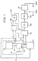
- a flow generator 10 comprises an electric motor 12 that drives a turbine 14.
- the turbine 14 provides a supply of air for the administration of CPAP treatment, transported to the patient's mask by an air delivery tube (not shown).
- the motor 12 receives electrical power from a power supply 16.
- a motor controller 18 which issues a control signal 20 to the power supply 16 to control the motor speed and thus the speed of the turbine 14 and, in turn, the flow rate in the air delivery tube.
- a speed feedback signal 22 is input to the motor controller 18 to provide a signal upon which speed regulation can be based.
- one of the interconnecting wires between the power supply 16 and the motor 12 is provided with a current sensing resistor 24.
- This resistor therefore detects current demanded by the motor 12, represented as the voltage appearing across the resistor 24. That voltage is sensed and input to a differential amplifier 26, thus producing an output signal representative of motor current (and thus also motor power).
- This output signal is then provided to a low-pass filter circuit 28 having an upper limiting frequency of, say, 20 Hz.
- the low-pass filter circuit 28 removes high frequency electrical noise, and also tends to average the signal.
- the filtered signal is then passed through a high-pass filter 30, typically with 0.5 Hz cut-off, to remove the non-respiratory components.
- the voltage drop across the motor 12 is measured via a differential amplifier 55.
- the output voltage thereof is then multiplied with the motor current signal previously derived by the differential amplifier 26 by a multiplier 27 to produce a measure of the time instantaneous power consumed by the motor.
- This time instantaneous power signal then is provided to the low pass filter circuit 28, and processing proceeds as described above.
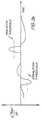
- the output of the high-pass filter circuit 30, shown as output signal 32, is supplied to an inhalation/exhalation detector (not shown) which functions to determine the start of inhalation and exhalation by locating the sudden changes of signal amplitude and/or polarity following a segment having a low rate of change with time and being of a given minimum duration, typically 0.2 second.
- Fig. 3a shows a typical flow characteristic, and identifies both the start of inhalation and exhalation events, that are detected by the methodology described. Therefore, the output signal 32 (FLOW) provides an indication of the instances of inhalation and exhalation, and these points are critical to the correct working of bi-level CPAP machines, for example.
- the output from the low-pass filter 28 can be input to a negative peak detector (not shown) which triggers a sample and hold circuit (also not shown) to latch the minimum point of the respiratory fluctuation.
- the detected minimum point of respiratory fluctuation can be updated periodically, typically as an exponentially past-time weighted sum of present and previous minimum measurements.
- Fig. 2 shows another method and apparatus for the detection of inhalation and exhalation events.
- a band-limited differentiator 42 receives the FLOW signal 32, derived from the high-pass filter circuit 30.
- the output from the differentiator 42 is supplied to a pair of comparators 44,46.
- This output signal, as a time differential, is represented in Fig. 3b.
- a threshold generator 48,50 Associated with each comparator 44,46 is a threshold generator 48,50.
- These generators 48,50 respectively have a threshold value for detecting inhalation and exhalation, as is shown in Fig. 3b.
- the comparator 44 will compare the time differentiated flow signal output from the differentiator 42 with the threshold value supplied by the threshold generator 48, and when that value is exceeded (in the negative sense) an inhalation detection signal 52 is output.
- the other comparator 46 functions in a similar way to output an exhalation detection signal 54 in the event that the time differentiator flow signal exceeds (in a positive sense) the threshold value set by the threshold generator 50.
- the low-pass filtered signal (the output of the low-pass filter 28) derived from the motor current can be digitised and input to a microcomputer where the subsequent signal processing described above is performed digitally.
- threshold levels and decision times can be varied dynamically to track the changing shape of the patient's respiratory flow.
Description
Claims (8)
- Apparatus for the detection of respiration during the administration of continuous positive airway pressure (CPAP) treatment by a CPAP system, said CPAP system including an electrical motor (12) coupled to a turbine (14) for supplying breathable gas to a mask via a gas delivery tube, said apparatus comprising:first measurement means (24,26) for measuring motor current to derive a motor current signal;second measurement means (25) for measuring motor voltage to derive a motor voltage signal; and characterised in that there further comprises:processor means (27) for deriving an instantaneous motor power signal as a multiplication of said motor voltage signal and said motor current signal;filter means (28,30) for filtering said instantaneous motor power signal to remove non-respiratory components; andsensing means (42) for sensing a change in said filtered instantaneous motor power signal as being indicative of a change in respiratory phase.
- Apparatus as claimed in claim 1, wherein said sensing means (42) includes differentiation means (42) for performing a time differentiation of said filtered instantaneous motor power signal.
- Apparatus as claimed in claim 2, further comprising:comparison means (44,46) for comparing said differentiated instantaneous motor power signal with a first threshold value to detect start of inhalation phase if said first threshold value is exceeded, and for comparing said differentiated instantaneous motor power signal with a second threshold value to detect start of exhalation phase if said second threshold value is exceeded.
- A system for the administration of CPAP treatment, said system comprising:an electrical motor (12);a turbine (14) coupled with said electrical motor for supplying breathable gas;a gas delivery tube coupled with said turbine to receive said breathable gas;a mask coupled with said delivery tube to deliver said breathable gas; andcontrol means (18) to control said motor and hence the pressure of breathable gas delivered by said turbine, different treatment pressures being delivered in synchronism with patient inspiration and expiration phases; andapparatus for the detection respiration phase change as defined in any one of claims 1 to 3.
- A method for detecting respiration during the administration of continuous positive airway pressure (CPAP) treatment by a CPAP system as defined in claim 4, said method comprising the steps of:measuring motor current to derive a motor current signal;measuring motor voltage to derive a motor voltage signal; and characterised byderiving an instantaneous motor power signal as a multiplication of said motor voltage signal and said motor current signal;filtering said instantaneous motor power signal to remove non-respiratory components; andsensing a change in said filtered instantaneous motor power signal as being indicative of a change in respiratory phase.
- A method as claimed in claim 5, whereby said sensing step comprises performing a time differentiation of said filtered instantaneous motor power signal.
- A method as claimed in claim 6, comprising the further steps of:comparing said differentiated instantaneous motor power signal with a first threshold value to detect start of inhalation phase if said first threshold value is exceeded; andcomparing said differentiated instantaneous motor power signal with a second threshold value to detect start of exhalation phase if said second threshold value is exceeded.
- A method as claimed in claim 7, comprising the further steps of: linearising said filtered instantaneous motor power signal with respect to ones of predetermined characteristics of said gas delivery tube and said mask relating flow to consumed power to provide a volumetric measure of respiratory flow.
Applications Claiming Priority (3)
| Application Number | Priority Date | Filing Date | Title |
|---|---|---|---|
| AUPM2793/93 | 1993-12-03 | ||
| AUPM2793A AUPM279393A0 (en) | 1993-12-03 | 1993-12-03 | Estimation of flow and detection of breathing in cpap treatment |
| AUPM279393 | 1993-12-03 |
Publications (3)
| Publication Number | Publication Date |
|---|---|
| EP0656216A2 EP0656216A2 (en) | 1995-06-07 |
| EP0656216A3 EP0656216A3 (en) | 1995-07-05 |
| EP0656216B1 true EP0656216B1 (en) | 2000-07-05 |
Family
ID=3777420
Family Applications (1)
| Application Number | Title | Priority Date | Filing Date |
|---|---|---|---|
| EP94308936A Expired - Lifetime EP0656216B1 (en) | 1993-12-03 | 1994-12-01 | Estimation of flow and detection of breathing in CPAP treatment |
Country Status (4)
| Country | Link |
|---|---|
| US (1) | US5740795A (en) |
| EP (1) | EP0656216B1 (en) |
| AU (1) | AUPM279393A0 (en) |
| DE (1) | DE69425113T2 (en) |
Cited By (7)
| Publication number | Priority date | Publication date | Assignee | Title |
|---|---|---|---|---|
| US6367474B1 (en) | 1997-11-07 | 2002-04-09 | Resmed Limited | Administration of CPAP treatment pressure in presence of APNEA |
| US6397841B1 (en) | 1997-06-18 | 2002-06-04 | Resmed Limited | Apparatus for supplying breathable gas |
| US6526974B1 (en) | 1995-09-18 | 2003-03-04 | John William Ernest Brydon | Pressure control in CPAP treatment or assisted respiration |
| US6532957B2 (en) | 1996-09-23 | 2003-03-18 | Resmed Limited | Assisted ventilation to match patient respiratory need |
| DE102004018029A1 (en) * | 2004-04-14 | 2005-11-03 | Weinmann Geräte für Medizin GmbH + Co. KG | Apparatus for ventilation and method for controlling a ventilator |
| DE10118968B4 (en) * | 2001-04-18 | 2007-03-01 | The Scientific Consulting Group Gmbh | A method for controlling the setpoint pressure of a device for performing CPAP therapy, and a device for performing CPAP therapy |
| AU2004208575B2 (en) * | 2003-01-27 | 2009-09-17 | Resmed Paris | Breathing assistance device, and method of regulation |
Families Citing this family (121)
| Publication number | Priority date | Publication date | Assignee | Title |
|---|---|---|---|---|
| EP0549299B1 (en) | 1991-12-20 | 2002-03-13 | Resmed Limited | Ventilator for continuous positive airway pressure breathing (CPAP) |
| US7758503B2 (en) * | 1997-01-27 | 2010-07-20 | Lynn Lawrence A | Microprocessor system for the analysis of physiologic and financial datasets |
| US6342039B1 (en) | 1992-08-19 | 2002-01-29 | Lawrence A. Lynn | Microprocessor system for the simplified diagnosis of sleep apnea |
| US6223064B1 (en) | 1992-08-19 | 2001-04-24 | Lawrence A. Lynn | Microprocessor system for the simplified diagnosis of sleep apnea |
| US7081095B2 (en) * | 2001-05-17 | 2006-07-25 | Lynn Lawrence A | Centralized hospital monitoring system for automatically detecting upper airway instability and for preventing and aborting adverse drug reactions |
| US20050062609A9 (en) * | 1992-08-19 | 2005-03-24 | Lynn Lawrence A. | Pulse oximetry relational alarm system for early recognition of instability and catastrophic occurrences |
| US5517983A (en) * | 1992-12-09 | 1996-05-21 | Puritan Bennett Corporation | Compliance meter for respiratory therapy |
| US6675797B1 (en) | 1993-11-05 | 2004-01-13 | Resmed Limited | Determination of patency of the airway |
| DE69422900T2 (en) | 1993-12-01 | 2000-06-08 | Resmed Ltd | Continuous positive airway pressure (CPAP) device |
| US6237593B1 (en) * | 1993-12-03 | 2001-05-29 | Resmed Limited | Estimation of flow and detection of breathing CPAP treatment |
| AUPN236595A0 (en) | 1995-04-11 | 1995-05-11 | Rescare Limited | Monitoring of apneic arousals |
| AUPN394895A0 (en) | 1995-07-03 | 1995-07-27 | Rescare Limited | Auto-calibration of pressure transducer offset |
| AUPN547895A0 (en) * | 1995-09-15 | 1995-10-12 | Rescare Limited | Flow estimation and compenstion of flow-induced pressure swings cpap treatment |
| AUPN616795A0 (en) * | 1995-10-23 | 1995-11-16 | Rescare Limited | Ipap duration in bilevel cpap or assisted respiration treatment |
| AUPO163896A0 (en) | 1996-08-14 | 1996-09-05 | Resmed Limited | Determination of respiratory airflow |
| AUPO301796A0 (en) | 1996-10-16 | 1996-11-07 | Resmed Limited | A vent valve apparatus |
| US9042952B2 (en) * | 1997-01-27 | 2015-05-26 | Lawrence A. Lynn | System and method for automatic detection of a plurality of SPO2 time series pattern types |
| US9468378B2 (en) * | 1997-01-27 | 2016-10-18 | Lawrence A. Lynn | Airway instability detection system and method |
| US20060155207A1 (en) * | 1997-01-27 | 2006-07-13 | Lynn Lawrence A | System and method for detection of incomplete reciprocation |
| US8932227B2 (en) | 2000-07-28 | 2015-01-13 | Lawrence A. Lynn | System and method for CO2 and oximetry integration |
| AUPO511397A0 (en) | 1997-02-14 | 1997-04-11 | Resmed Limited | An apparatus for varying the flow area of a conduit |
| DE19706092C2 (en) | 1997-02-17 | 2000-02-24 | Map Gmbh | Procedure for switching to the inhalation or exhalation phase with a CPAP therapy device |
| WO1998051362A1 (en) * | 1997-05-16 | 1998-11-19 | Peter Craig Farrell | Nasal ventilation as a treatment for stroke |
| US10130787B2 (en) | 1997-06-17 | 2018-11-20 | Fisher & Paykel Healthcare Limited | Humidity controller |
| US20040221844A1 (en) | 1997-06-17 | 2004-11-11 | Hunt Peter John | Humidity controller |
| US20080287756A1 (en) * | 1997-07-14 | 2008-11-20 | Lynn Lawrence A | Pulse oximetry relational alarm system for early recognition of instability and catastrophic occurrences |
| US20070191697A1 (en) * | 2006-02-10 | 2007-08-16 | Lynn Lawrence A | System and method for SPO2 instability detection and quantification |
| FR2767466B1 (en) | 1997-08-25 | 1999-10-15 | Taema | METHOD FOR DETERMINING THE IMAGE OF A NASAL AND / OR ORAL RESPIRATORY FLOW OF A USER |
| USD421298S (en) * | 1998-04-23 | 2000-02-29 | Resmed Limited | Flow generator |
| AUPP366398A0 (en) | 1998-05-22 | 1998-06-18 | Resmed Limited | Ventilatory assistance for treatment of cardiac failure and cheyne-stokes breathing |
| FR2779932B1 (en) | 1998-06-18 | 2000-12-01 | Taema | DEVICE FOR DETERMINING RESPIRATORY PHASES OF THE SLEEP OF A USER |
| US6626176B1 (en) | 1998-08-19 | 2003-09-30 | Map Medizintechnik Fur Arzt Und Patient Gmbh & Co. Kg | Method and device for switching the inspiration or expiration phase during CPAP therapy |
| AUPP688998A0 (en) | 1998-11-02 | 1998-11-26 | Resmed Limited | Fast accelerating flow generator |
| AUPP693398A0 (en) | 1998-11-05 | 1998-12-03 | Resmed Limited | Fault diagnosis in CPAP and NIPPV devices |
| US7073501B2 (en) * | 1999-02-04 | 2006-07-11 | Univerity Technologies International Inc. | Ventilatory stabilization technology |
| US6752150B1 (en) | 1999-02-04 | 2004-06-22 | John E. Remmers | Ventilatory stabilization technology |
| FR2793145B1 (en) * | 1999-05-04 | 2003-10-24 | Map Medizintechnik Fur Arzt Un | DEVICE FOR SUPPLYING RESPIRATORY GAS TO SURPRESSION AND CONTROL ARRANGEMENT FOR CONTROLLING THE SAME |
| US7219669B1 (en) | 1999-06-08 | 2007-05-22 | Sleepnet Corporation | Nose mask |
| US6631718B1 (en) | 1999-06-08 | 2003-10-14 | Sleepnet Corporation | Air mask with seal |
| FR2794635B1 (en) * | 1999-06-14 | 2001-08-03 | Taema | APPARATUS FOR DIAGNOSING OR TREATING SLEEP BREATHING DISORDERS AND METHOD OF OPERATION |
| US6895963B1 (en) * | 1999-06-16 | 2005-05-24 | Resmed Limited | Apparatus with automatic respiration monitoring and display |
| CN1230221C (en) | 1999-08-23 | 2005-12-07 | 菲舍尔和佩克尔保健有限公司 | Humidity controller |
| DE10031079A1 (en) * | 2000-06-30 | 2002-02-07 | Map Gmbh | Measuring patient breathing and state, correlates present respiration signals with prior reference measurements, to adjust CPAP therapy pressure accordingly |
| US6814073B2 (en) | 2000-08-29 | 2004-11-09 | Resmed Limited | Respiratory apparatus with improved flow-flattening detection |
| EP1322367A4 (en) * | 2000-09-28 | 2009-08-26 | Invacare Corp | Carbon dioxide-based bi-level cpap control |
| DE20017940U1 (en) | 2000-10-19 | 2000-12-28 | Map Gmbh | Breathing mask for supplying a breathing gas to a mask user and a derivation device for deriving breathing gas |
| ATE422167T1 (en) | 2000-10-19 | 2009-02-15 | Mallinckrodt Inc | VENTILATOR WITH DUAL GAS SUPPLY |
| DE10103810A1 (en) | 2001-01-29 | 2002-08-01 | Map Gmbh | Device for supplying a breathing gas |
| US9053222B2 (en) * | 2002-05-17 | 2015-06-09 | Lawrence A. Lynn | Patient safety processor |
| DE10139881B4 (en) * | 2001-08-20 | 2017-06-08 | Resmed R&D Germany Gmbh | Apparatus for supplying a breathing gas and method for controlling the same |
| DE10201682A1 (en) | 2002-01-17 | 2003-07-31 | Map Medizin Technologie Gmbh | The breathing mask arrangement |
| DE50214539D1 (en) | 2001-10-22 | 2010-08-26 | Map Medizin Technologie Gmbh | Medical mask |
| DE10151984C5 (en) | 2001-10-22 | 2008-07-17 | Map Medizin-Technologie Gmbh | Application device for a breathing mask arrangement |
| DE10161057A1 (en) * | 2001-12-12 | 2003-07-10 | Heptec Gmbh | Process for controlling the differential pressure in a CPAP device and CPAP device |
| US6968842B1 (en) | 2002-04-03 | 2005-11-29 | Ric Investments, Inc. | Measurement of a fluid parameter in a pressure support system |
| US6668729B1 (en) * | 2002-08-21 | 2003-12-30 | Bryan Richards | Transit system |
| US7890342B1 (en) | 2002-08-27 | 2011-02-15 | Ric Investments, Llc | Method and system for tracking and monitoring patient compliance with medical device usage prescription |
| ES2559034T3 (en) | 2002-09-06 | 2016-02-10 | Resmed Limited | Forehead pad for a respiratory mask |
| US7661426B2 (en) * | 2002-11-19 | 2010-02-16 | Michael Lauk | Method for controlling the pressure supplied by a CPAP device, CPAP device and storage medium |
| DE10253935B3 (en) * | 2002-11-19 | 2004-03-25 | Seleon Gmbh | Controlling pressure delivered by continuous positive airway pressure device involves slow, quasi-ramp-shaped reduction of pressure delivered by device as long as there is no respiratory event |
| DE10253937B3 (en) * | 2002-11-19 | 2004-01-15 | Seleon Gmbh | Fan units for a ventilator |
| DE10253946B3 (en) * | 2002-11-19 | 2004-01-29 | Seleon Gmbh | Procedure for a ventilator, ventilator and storage medium |
| US20050211249A1 (en) * | 2002-11-19 | 2005-09-29 | Mirko Wagner | Ventilator method, ventilator and memory medium |
| EP3308818A1 (en) * | 2003-05-02 | 2018-04-18 | ResMed Ltd. | Mask system |
| US8020555B2 (en) * | 2003-06-18 | 2011-09-20 | New York University | System and method for improved treatment of sleeping disorders using therapeutic positive airway pressure |
| US7621270B2 (en) * | 2003-06-23 | 2009-11-24 | Invacare Corp. | System and method for providing a breathing gas |
| US7152598B2 (en) | 2003-06-23 | 2006-12-26 | Invacare Corporation | System and method for providing a breathing gas |
| US7114497B2 (en) * | 2003-07-18 | 2006-10-03 | Acoba, Llc | Method and system of individually controlling airway pressure of a patient's nares |
| US6988994B2 (en) * | 2003-08-14 | 2006-01-24 | New York University | Positive airway pressure system and method for treatment of sleeping disorder in patient |
| US7343917B2 (en) | 2003-09-22 | 2008-03-18 | Resmed Limited | Clear cycle for ventilation device |
| JP4977477B2 (en) * | 2004-02-11 | 2012-07-18 | レスメド・リミテッド | Adjusting the device for each session to treat sleep breathing disorders |
| DE102004014538A1 (en) | 2004-03-23 | 2005-10-13 | Seleon Gmbh | Method for controlling a BiLevel device and BiLevel device |
| US7878198B2 (en) * | 2004-03-31 | 2011-02-01 | Michael Farrell | Methods and apparatus for monitoring the cardiovascular condition of patients with sleep disordered breathing |
| US7276031B2 (en) * | 2004-05-12 | 2007-10-02 | New York University | System and method for classifying patient's breathing using artificial neural network |
| US20050268912A1 (en) * | 2004-06-04 | 2005-12-08 | Norman Robert G | System and method for automated titration of continuous positive airway pressure |
| JP5002453B2 (en) | 2004-06-23 | 2012-08-15 | レスメド・リミテッド | Methods and equipment with improved ventilation support cycle |
| US20060005834A1 (en) * | 2004-07-07 | 2006-01-12 | Acoba, Llc | Method and system of providing therapeutic gas to a patient to prevent breathing airway collapse |
| US7882834B2 (en) * | 2004-08-06 | 2011-02-08 | Fisher & Paykel Healthcare Limited | Autotitrating method and apparatus |
| AU2005301097B2 (en) * | 2004-11-04 | 2012-03-15 | ResMed Pty Ltd | Using motor speed in a PAP device to estimate flow |
| US20060174885A1 (en) * | 2005-02-08 | 2006-08-10 | Acoba, Llc | Method and related system to control applied pressure in CPAP systems |
| DE102005012753A1 (en) * | 2005-03-19 | 2006-09-28 | Weinmann Geräte für Medizin GmbH & Co. KG | Breathing apparatus for patients has control unit for compressed gas source and sequence valve for enriching breathing gas with oxygen that is connected to control unit |
| US8739780B2 (en) | 2005-08-15 | 2014-06-03 | Resmed Limited | Low cost CPAP flow generator and humidifier assembly |
| NZ591992A (en) | 2005-10-14 | 2012-11-30 | Resmed Ltd | Breathing mask with cushion attached to frame via lip of cushion engaging within recess between frame outer and inner walls, and guided in via angled protrusion of frame inner wall |
| NZ612787A (en) | 2005-10-25 | 2015-01-30 | Resmed Ltd | Interchangeable mask assembly |
| US7706852B2 (en) * | 2006-01-30 | 2010-04-27 | Nellcor Puritan Bennett Llc | System and method for detection of unstable oxygen saturation |
| US7668579B2 (en) * | 2006-02-10 | 2010-02-23 | Lynn Lawrence A | System and method for the detection of physiologic response to stimulation |
| EP2035070B1 (en) | 2006-06-30 | 2019-10-30 | Breas Medical AB | Energy relief control in a mechanical ventilator |
| US8517023B2 (en) | 2007-01-30 | 2013-08-27 | Resmed Limited | Mask system with interchangeable headgear connectors |
| EP2144674A4 (en) * | 2007-04-13 | 2012-12-26 | Invacare Corp | Apparatus and method for providing positive airway pressure |
| CN103893870B (en) | 2007-05-11 | 2016-10-05 | 瑞思迈有限公司 | For automatically controlling of flow restriction detection |
| EP2173249A4 (en) * | 2007-07-26 | 2013-07-24 | Uti Limited Partnership | Transient intervention for modifying the breathing of a patient |
| AU2008203812B2 (en) * | 2007-08-17 | 2014-10-02 | ResMed Pty Ltd | Methods and Apparatus for Pressure Therapy in the Treatment of Sleep Disordered Breathing |
| US8261742B2 (en) | 2007-08-23 | 2012-09-11 | Invacare Corporation | Method and apparatus for adjusting desired pressure in positive airway pressure devices |
| US20090078255A1 (en) * | 2007-09-21 | 2009-03-26 | Bowman Bruce R | Methods for pressure regulation in positive pressure respiratory therapy |
| CN101888870B (en) * | 2007-10-26 | 2013-11-27 | 优特埃合伙有限公司 | Ventilation stabilization system |
| US8275553B2 (en) * | 2008-02-19 | 2012-09-25 | Nellcor Puritan Bennett Llc | System and method for evaluating physiological parameter data |
| DE202009019168U1 (en) | 2008-03-04 | 2017-06-20 | Resmed Ltd. | mask system |
| US9802022B2 (en) * | 2008-03-06 | 2017-10-31 | Resmed Limited | Humidification of respiratory gases |
| US8365730B2 (en) | 2008-03-24 | 2013-02-05 | Covidien Lp | Method and system for classification of photo-plethysmographically detected respiratory effort |
| US20090247837A1 (en) * | 2008-03-27 | 2009-10-01 | Nellcor Puritan Bennett Llc | System And Method For Diagnosing Sleep Apnea |
| US8398555B2 (en) * | 2008-09-10 | 2013-03-19 | Covidien Lp | System and method for detecting ventilatory instability |
| AU2010206053B2 (en) | 2009-07-31 | 2014-08-07 | ResMed Pty Ltd | Wire Heated Tube with Temperature Control System, Tube Type Detection, and Active Over Temperature Protection for Humidifier for Respiratory Apparatus |
| US8991392B1 (en) | 2010-12-21 | 2015-03-31 | Fisher & Paykel Healthcare Limited | Pressure adjustment method for CPAP machine |
| JP6396892B2 (en) * | 2012-05-14 | 2018-09-26 | レスメド・モーター・テクノロジーズ・インコーポレーテッド | Pressure control for breathing comfort |
| CN103893865B (en) * | 2012-12-26 | 2017-05-31 | 北京谊安医疗系统股份有限公司 | A kind of method of lung ventilator turbine volume controlled ventilation |
| NZ743034A (en) | 2013-02-01 | 2019-12-20 | ResMed Pty Ltd | Wire heated tube with temperature control system for humidifier for respiratory apparatus |
| CN104750129B (en) * | 2013-12-26 | 2019-08-06 | 北京谊安医疗系统股份有限公司 | The control system and control method of the ventilation flow rate of ventilator |
| US10893825B2 (en) * | 2014-01-31 | 2021-01-19 | North Carolina State University | System and method of monitoring respiratory parameters |
| US9731089B2 (en) * | 2014-02-14 | 2017-08-15 | Breathe Technologies, Inc. | Sleep detection for controlling continuous positive airway pressure therapy |
| EP4039313A1 (en) | 2014-03-13 | 2022-08-10 | ResMed Pty Ltd | A humidifier for a respiratory therapy device |
| US9808591B2 (en) | 2014-08-15 | 2017-11-07 | Covidien Lp | Methods and systems for breath delivery synchronization |
| CN104527351A (en) * | 2015-01-01 | 2015-04-22 | 石河子大学 | Towing and maintaining device applied to high-ground-clearance sprayer chassis |
| US11497870B2 (en) | 2015-02-24 | 2022-11-15 | Somnetics International, Inc. | Systems and methods for estimating flow in positive airway pressure therapy |
| CN104688232B (en) * | 2015-03-23 | 2017-12-01 | 北京怡和嘉业医疗科技股份有限公司 | The detection method and equipment of a kind of sleep apnea |
| US11065408B2 (en) | 2015-10-05 | 2021-07-20 | UNIVERSITé LAVAL | Method for delivery of breathing gas to a patient and system for performing same |
| US11298074B2 (en) | 2015-12-08 | 2022-04-12 | Fisher & Paykel Healthcare Limited | Flow-based sleep stage determination |
| WO2018042974A1 (en) * | 2016-08-29 | 2018-03-08 | 株式会社村田製作所 | Pump device |
| WO2019060947A1 (en) * | 2017-09-28 | 2019-04-04 | CleanSpace IP Pty Ltd | Portable personal respirator and use thereof |
| CN109893736A (en) * | 2017-12-07 | 2019-06-18 | 北京怡和嘉业医疗科技股份有限公司 | Data processing method and device based on positive airway pressure machine |
| US11904094B2 (en) * | 2019-09-09 | 2024-02-20 | Koninklijke Philips N.V. | Pressure and oxygen mix control for single limb non-invasive ventilation |
| EP4252813A1 (en) * | 2022-03-30 | 2023-10-04 | Koninklijke Philips N.V. | High flow nasal therapy system and method |
Family Cites Families (35)
| Publication number | Priority date | Publication date | Assignee | Title |
|---|---|---|---|---|
| BE791154A (en) * | 1971-11-10 | 1973-05-09 | Synthelabo | TURBINE RESPIRATOR |
| US3834383A (en) * | 1972-12-11 | 1974-09-10 | Puritan Bennett Corp | Respiration apparatus with flow responsive control valve |
| US3972327A (en) * | 1973-03-22 | 1976-08-03 | Hoffmann-La Roche Inc. | Respirator |
| US3840006A (en) * | 1973-04-26 | 1974-10-08 | Department Of Health Education | Respirator |
| CH568756A5 (en) * | 1973-09-07 | 1975-11-14 | Hoffmann La Roche | |
| US4239039A (en) * | 1979-02-28 | 1980-12-16 | Thompson Harris A | Dual control valve for positive pressure artificial respiration apparatus |
| US4347468A (en) * | 1980-04-28 | 1982-08-31 | Lake Center Industries | Electronic variable speed automotive blower control system |
| DE3276924D1 (en) * | 1981-04-24 | 1987-09-17 | Somed Pty Ltd | Device for treating snoring sickness |
| US4430995A (en) * | 1981-05-29 | 1984-02-14 | Hilton Joseph R | Power assisted air-purifying respirators |
| FR2517961A1 (en) * | 1981-12-11 | 1983-06-17 | Synthelabo Biomedical | METHOD AND DEVICE FOR CONTROLLING ARTIFICIAL RESPIRATION |
| US4506666A (en) * | 1982-12-03 | 1985-03-26 | Kircaldie, Randall And Mcnab | Method and apparatus for rectifying obstructive apnea |
| IL71468A (en) * | 1984-04-08 | 1988-06-30 | Dan Atlas | Apnea monitoring method and apparatus |
| DE3422066A1 (en) * | 1984-06-14 | 1985-12-19 | Drägerwerk AG, 2400 Lübeck | VENTILATION SYSTEM AND CONTROLLABLE VALVE UNIT TO |
| FR2568397B1 (en) * | 1984-07-27 | 1987-08-14 | Mequignon Jean Claude | PROCESS FOR STOPPING THE HUMAN SNORING OF ITS EMISSIONS AND APPARATUS NECESSARY FOR THE IMPLEMENTATION OF THIS PROCESS |
| EP0218690A4 (en) * | 1985-04-10 | 1987-07-22 | Emergent Technology Corp | Multi-channel ventilation monitor and method. |
| JPS6294175A (en) * | 1985-10-18 | 1987-04-30 | 鳥取大学長 | Respiration synchronous type gas blowing apparatus and method |
| SE451232C (en) * | 1985-10-25 | 1992-03-04 | Carl Eric Persson | DEVICE FOR THE PREVENTION OF SNORING FROM A SLEEPING PERSON |
| US4828257A (en) * | 1986-05-20 | 1989-05-09 | Powercise International Corporation | Electronically controlled exercise system |
| US5024219A (en) * | 1987-01-12 | 1991-06-18 | Dietz Henry G | Apparatus for inhalation therapy using triggered dose oxygenator employing an optoelectronic inhalation sensor |
| US5199424A (en) * | 1987-06-26 | 1993-04-06 | Sullivan Colin E | Device for monitoring breathing during sleep and control of CPAP treatment that is patient controlled |
| WO1988010108A1 (en) * | 1987-06-26 | 1988-12-29 | Travenol Centre For Medical Research | Device for monitoring breathing during sleep and control of cpap treatment |
| US4782832A (en) * | 1987-07-30 | 1988-11-08 | Puritan-Bennett Corporation | Nasal puff with adjustable sealing means |
| FI80606C (en) * | 1987-10-05 | 1990-07-10 | Kemira Oy | FOERFARANDE FOER REGLERING AV LUFTMAONGDEN SOM MATAS IN I EN GASMASK SAMT EN GASMASK SOM GENOMFOER DENNA FOERFARANDE. |
| US4938212A (en) * | 1987-10-16 | 1990-07-03 | Puritan-Bennett Corporation | Inspiration oxygen saver |
| US4915103A (en) * | 1987-12-23 | 1990-04-10 | N. Visveshwara, M.D., Inc. | Ventilation synchronizer |
| US4823788A (en) * | 1988-04-18 | 1989-04-25 | Smith Richard F M | Demand oxygen controller and respiratory monitor |
| US5134995A (en) * | 1989-05-19 | 1992-08-04 | Puritan-Bennett Corporation | Inspiratory airway pressure system with admittance determining apparatus and method |
| US5239995A (en) * | 1989-09-22 | 1993-08-31 | Respironics, Inc. | Sleep apnea treatment apparatus |
| US5117819A (en) * | 1990-09-10 | 1992-06-02 | Healthdyne, Inc. | Nasal positive pressure device |
| FR2674133B1 (en) * | 1991-03-21 | 1993-06-11 | Taema | RESPIRATORY GAS PRESSURE SUPPLY SYSTEM AND METHOD FOR CONTROLLING SUCH A SYSTEM. |
| US5458137A (en) * | 1991-06-14 | 1995-10-17 | Respironics, Inc. | Method and apparatus for controlling sleep disorder breathing |
| US5385142A (en) * | 1992-04-17 | 1995-01-31 | Infrasonics, Inc. | Apnea-responsive ventilator system and method |
| US5490502A (en) * | 1992-05-07 | 1996-02-13 | New York University | Method and apparatus for optimizing the continuous positive airway pressure for treating obstructive sleep apnea |
| US5335654A (en) * | 1992-05-07 | 1994-08-09 | New York University | Method and apparatus for continuous adjustment of positive airway pressure for treating obstructive sleep apnea |
| US5535738A (en) * | 1994-06-03 | 1996-07-16 | Respironics, Inc. | Method and apparatus for providing proportional positive airway pressure to treat sleep disordered breathing |
-
1993
- 1993-12-03 AU AUPM2793A patent/AUPM279393A0/en not_active Abandoned
-
1994
- 1994-12-01 DE DE69425113T patent/DE69425113T2/en not_active Expired - Lifetime
- 1994-12-01 EP EP94308936A patent/EP0656216B1/en not_active Expired - Lifetime
- 1994-12-02 US US08/348,580 patent/US5740795A/en not_active Expired - Lifetime
Cited By (8)
| Publication number | Priority date | Publication date | Assignee | Title |
|---|---|---|---|---|
| US6526974B1 (en) | 1995-09-18 | 2003-03-04 | John William Ernest Brydon | Pressure control in CPAP treatment or assisted respiration |
| US6532957B2 (en) | 1996-09-23 | 2003-03-18 | Resmed Limited | Assisted ventilation to match patient respiratory need |
| US6688307B2 (en) | 1996-09-23 | 2004-02-10 | Resmed Limited | Methods and apparatus for determining instantaneous elastic recoil and assistance pressure during ventilatory support |
| US6397841B1 (en) | 1997-06-18 | 2002-06-04 | Resmed Limited | Apparatus for supplying breathable gas |
| US6367474B1 (en) | 1997-11-07 | 2002-04-09 | Resmed Limited | Administration of CPAP treatment pressure in presence of APNEA |
| DE10118968B4 (en) * | 2001-04-18 | 2007-03-01 | The Scientific Consulting Group Gmbh | A method for controlling the setpoint pressure of a device for performing CPAP therapy, and a device for performing CPAP therapy |
| AU2004208575B2 (en) * | 2003-01-27 | 2009-09-17 | Resmed Paris | Breathing assistance device, and method of regulation |
| DE102004018029A1 (en) * | 2004-04-14 | 2005-11-03 | Weinmann Geräte für Medizin GmbH + Co. KG | Apparatus for ventilation and method for controlling a ventilator |
Also Published As
| Publication number | Publication date |
|---|---|
| AUPM279393A0 (en) | 1994-01-06 |
| DE69425113T2 (en) | 2000-11-16 |
| EP0656216A2 (en) | 1995-06-07 |
| EP0656216A3 (en) | 1995-07-05 |
| US5740795A (en) | 1998-04-21 |
| DE69425113D1 (en) | 2000-08-10 |
Similar Documents
| Publication | Publication Date | Title |
|---|---|---|
| EP0656216B1 (en) | Estimation of flow and detection of breathing in CPAP treatment | |
| US6237593B1 (en) | Estimation of flow and detection of breathing CPAP treatment | |
| US6659101B2 (en) | Determination of leak and respiratory airflow | |
| US10918329B2 (en) | Distinguishing closed and open respiratory airway apneas by complex admittance values | |
| US8256417B2 (en) | Method and apparatus for providing positive airway pressure to a patient | |
| US6575163B1 (en) | Method for calculating the instantaneous inspired volume of a subject during ventilatory assistance | |
| EP0714670B1 (en) | Breathing gas delivery apparatus | |
| US6213119B1 (en) | Inspiratory duration in CPAP or assisted respiration treatment | |
| US6895963B1 (en) | Apparatus with automatic respiration monitoring and display | |
| EP1991297B1 (en) | Determination of apnea/hypopnea during cpap treatment | |
| CA2520745C (en) | Determination of leak and respiratory airflow | |
| AU2002306200B2 (en) | Determination of Leak and Respiratory Airflow | |
| AU2005200987B2 (en) | Determination of Leak and Respiratory Airflow | |
| AU756622B2 (en) | Determination of leak and respiratory airflow | |
| AU2015249041A1 (en) | Distinguishing Closed and Open Respiratory Airway Apneas by Complex Admittance Values |
Legal Events
| Date | Code | Title | Description |
|---|---|---|---|
| PUAI | Public reference made under article 153(3) epc to a published international application that has entered the european phase |
Free format text: ORIGINAL CODE: 0009012 |
|
| PUAL | Search report despatched |
Free format text: ORIGINAL CODE: 0009013 |
|
| AK | Designated contracting states |
Kind code of ref document: A2 Designated state(s): DE FR GB |
|
| AK | Designated contracting states |
Kind code of ref document: A3 Designated state(s): DE FR GB |
|
| 17P | Request for examination filed |
Effective date: 19951213 |
|
| 17Q | First examination report despatched |
Effective date: 19981126 |
|
| GRAG | Despatch of communication of intention to grant |
Free format text: ORIGINAL CODE: EPIDOS AGRA |
|
| GRAG | Despatch of communication of intention to grant |
Free format text: ORIGINAL CODE: EPIDOS AGRA |
|
| GRAH | Despatch of communication of intention to grant a patent |
Free format text: ORIGINAL CODE: EPIDOS IGRA |
|
| GRAH | Despatch of communication of intention to grant a patent |
Free format text: ORIGINAL CODE: EPIDOS IGRA |
|
| GRAA | (expected) grant |
Free format text: ORIGINAL CODE: 0009210 |
|
| AK | Designated contracting states |
Kind code of ref document: B1 Designated state(s): DE FR GB |
|
| REF | Corresponds to: |
Ref document number: 69425113 Country of ref document: DE Date of ref document: 20000810 |
|
| ET | Fr: translation filed | ||
| PLBE | No opposition filed within time limit |
Free format text: ORIGINAL CODE: 0009261 |
|
| STAA | Information on the status of an ep patent application or granted ep patent |
Free format text: STATUS: NO OPPOSITION FILED WITHIN TIME LIMIT |
|
| 26N | No opposition filed | ||
| REG | Reference to a national code |
Ref country code: GB Ref legal event code: IF02 |
|
| PGFP | Annual fee paid to national office [announced via postgrant information from national office to epo] |
Ref country code: GB Payment date: 20131127 Year of fee payment: 20 Ref country code: DE Payment date: 20131127 Year of fee payment: 20 |
|
| PGFP | Annual fee paid to national office [announced via postgrant information from national office to epo] |
Ref country code: FR Payment date: 20131209 Year of fee payment: 20 |
|
| REG | Reference to a national code |
Ref country code: DE Ref legal event code: R071 Ref document number: 69425113 Country of ref document: DE |
|
| REG | Reference to a national code |
Ref country code: GB Ref legal event code: PE20 Expiry date: 20141130 |
|
| PG25 | Lapsed in a contracting state [announced via postgrant information from national office to epo] |
Ref country code: GB Free format text: LAPSE BECAUSE OF EXPIRATION OF PROTECTION Effective date: 20141130 |