EP0656580A2 - Method and system for automatic storage of an object within a container object within a graphical user interface within a data processing system - Google Patents
Method and system for automatic storage of an object within a container object within a graphical user interface within a data processing system Download PDFInfo
- Publication number
- EP0656580A2 EP0656580A2 EP94480120A EP94480120A EP0656580A2 EP 0656580 A2 EP0656580 A2 EP 0656580A2 EP 94480120 A EP94480120 A EP 94480120A EP 94480120 A EP94480120 A EP 94480120A EP 0656580 A2 EP0656580 A2 EP 0656580A2
- Authority
- EP
- European Patent Office
- Prior art keywords
- container
- user interface
- graphical user
- data processing
- processing system
- Prior art date
- Legal status (The legal status is an assumption and is not a legal conclusion. Google has not performed a legal analysis and makes no representation as to the accuracy of the status listed.)
- Granted
Links
- 238000000034 method Methods 0.000 title claims abstract description 53
- 230000004044 response Effects 0.000 claims abstract description 11
- 230000008520 organization Effects 0.000 claims abstract description 4
- 230000008569 process Effects 0.000 description 40
- 230000000694 effects Effects 0.000 description 4
- 230000006870 function Effects 0.000 description 2
- 230000009471 action Effects 0.000 description 1
- 230000004048 modification Effects 0.000 description 1
- 238000012986 modification Methods 0.000 description 1
Images


Classifications
-
- G—PHYSICS
- G06—COMPUTING; CALCULATING OR COUNTING
- G06F—ELECTRIC DIGITAL DATA PROCESSING
- G06F3/00—Input arrangements for transferring data to be processed into a form capable of being handled by the computer; Output arrangements for transferring data from processing unit to output unit, e.g. interface arrangements
- G06F3/01—Input arrangements or combined input and output arrangements for interaction between user and computer
- G06F3/048—Interaction techniques based on graphical user interfaces [GUI]
- G06F3/0481—Interaction techniques based on graphical user interfaces [GUI] based on specific properties of the displayed interaction object or a metaphor-based environment, e.g. interaction with desktop elements like windows or icons, or assisted by a cursor's changing behaviour or appearance
Definitions
- the present invention relates in general to an improved graphical user interface in a data processing system and in particular to a method and system for the automatic storage of an object within a container object within a graphical user interface in a data processing system. Still more particularly, the present invention relates to a method and system for the automatic storage of an object within a container object within a graphical user interface in a data processing system in response to completion of utilization of the object.
- Data processing systems commonly utilize graphical user interfaces to enable users to interact with the data processing system and manipulate the activities and functions available to the users. Users may select, through the graphical user interface, a particular activity to perform utilizing input devices such as a keyboard or a "mouse.”
- activities such as "print document” or “select a document” may be represented to the user in the form of function keys graphically displayed on the computer display screen and selected by striking a particular key on the keyboard, or as icons to be selected utilizing a graphical pointing device such as a "mouse.”
- a pointer, or mouse cursor, on the display screen is typically utilized to represent the current location of the "mouse.” By moving the "mouse,” a user may move the pointer, or mouse cursor, around within the computer display screen.
- An object may be graphically represented to a user as an "icon" utilizing the graphical user interface.
- An object is an item which may be manipulated as a unit.
- Objects may be of three types: device, data, or container.
- a device object may be manipulated to perform a selected task such as typically performed utilizing a physical or logical device such as a printer, mouse, or facsimile machine.
- a "printer” device object may be manipulated to print documents or text.
- Data objects may include documents or text, such as created utilizing word processing applications.
- Container objects are typically objects into which other objects may be stored. Therefore, objects may be stored together in a container object and manipulated as a unit by manipulating the container object.
- Container objects are typically provided as part of a graphical user interface. These “folders” may be iconically represented as a traditional filing folder and may be utilized to group, or "store,” other objects in a way which is meaningful to a user. Such “folders” typically require a user to perform some action in order to select, locate and "store” objects within the “folder.” Some known container objects may also be manipulated to perform user specified activities utilizing the objects stored within the container object. For example, a user may specify that all objects stored within a selected container object be printed.
- a graphical user interface may display multiple icons which represent objects.
- a user may utilize an object by positioning a mouse cursor over the icon representing the object, and clicking a mouse button to "open" the object. Once an object is opened, the contents of the object appear displayed in a window.
- a window is an area of the graphical user interface with visible boundaries within which information is displayed.
- Windows typically include a border completely surrounding the window, a status line indicating the name of the window or application being displayed in the window, various buttons to be utilized to maximize or minimize the size of the window, and pull-down menus which may be accessed by selecting a display element.
- Windows also typically appear in a color or shade different from the color or shade of the background of the graphical user interface in order to distinguish the window from the rest of the graphical user interface.
- a user may then utilize the object, such as by revising the text of an object created by a word processing application. Once a user has completed the utilization, the user may store the revisions and "close" the application at which time the window will disappear.
- a container object may be utilized to group objects.
- a user may utilize an object grouped within a container object by first "opening" the container object, viewing the contents of the container object, and then selecting and “opening” an object, as described above, stored within the container object.
- a user may utilize an object stored within a container object without actually removing the object from its container object. Once the user has completed utilization of the object, the user may "close” the object. When the object is closed, the window utilized to display the contents of the object will disappear, and the object remains stored in its container object throughout the utilization of the object.
- a user may desire to first remove an object from its container object before utilizing it.
- a user must first "open” a container object, and then select and remove the object from its container object. The object may then be utilized. Once the object is removed from its container object, it is no longer associated with the container object. Therefore, when the object is "closed,” it is no longer stored in its original container object. Once the object is "closed,” it is stored in its current location. Its current location may be in a different container object, or in the graphical user interface independently of any container object.
- a method and system are disclosed for the automatic storage of an object within a container object within a graphical user interface within a data processing system.
- a display included within the data processing system, is utilized to display an iconic representation of a container object which is a graphic indication of a storage of objects.
- An object and a container object within the graphical user interface are specified.
- the object is thereafter associated with the container object.
- utilization the object is removed from the container object.
- the object is then automatically stored within the container object in response to a completion of the utilization, wherein the organization of objects within the container object and the graphical user interface are enhanced.
- Data processing system 10 includes a central processing unit (CPU) 8, which may be the processor of a host computer or the microprocessor of a work station or personal computer or the like.
- CPU central processing unit
- known means such as a bus 12 are employed to connect the CPU 8 to one or more interface devices, such as keyboard 16, a mouse 18, and/or other interface devices 21a and 21b, which can be any user interface device, such as a touch sensitive screen, a digitized pen entry pad, etc.
- a display device 20, such as an LCD screen or CRT screen, is connected to CPU 8 via a display adapter 24.
- CPU 8 is also connected to memory 26, which can include ROM, RAM, etc.
- memory 26 can include ROM, RAM, etc.
- CPU 8 is suitably programmed to implement the logic flow charts of Figures 5 through 8 in order to provide automatic storage of an object within a container object in a graphical user interface in a data processing system.
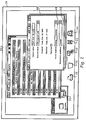
- Figure 2 illustrates a graphical user interface including an object and a setting's page of the object, wherein a home location may be specified in accordance with the present invention.
- An object may be graphically represented to a user as an "icon" utilizing the graphical user interface.
- An object is an item which may be manipulated as a unit.
- Container objects are typically objects into which other objects may be stored. Therefore, objects may be stored together in a container object and manipulated as a unit by manipulating the container object.
- a container object 32 is displayed within graphical user interface 30 and may be utilized to group related objects. For example, container object 32 may be utilized to group objects associated with the days of October. An object 34 has been removed from container object 32 and opened to display the contents of object 34. Other icons 36, 38, 40, 42, and 44 are also displayed within graphical user interface 30. These icons may represent any type of object.
- a user may remove object 34 from container object 32 in order to utilize it.
- object 34 Once a user has completed utilizing object 34, the user must remember the home location for object 34, and must physically return object 34 to its home.
- object 34 or an icon representing an object, may be manipulated, such as by removal, and returned to a container object.
- a home location for object 34 may be specified in home location field 48 within a settings page 46 of object 34.
- a settings page associated with each object is utilized to define characteristics of the object, such as object name, security level, creation and modification dates.
- object 34 may be automatically returned to its specified home location, or a temporary location, if one is specified.
- a temporary location may be specified in temporary location field 50 within settings page 46.
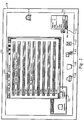
- Figure 3 depicts a graphical user interface including an object and an indication that the object is being returned to its home location in accordance with the present invention.
- Icon 52 represents object 34.
- a user may select "Return Home” in menu 54 in order to return object 34 to its specified home location, container object 32.
- An arrow is displayed in Figure 3 for illustrative purposes to indicate object 34, represented as icon 52, being returned to container object 32.
- Figure 4 illustrates a graphical user interface including an object and an indication of the home location of the object in accordance with the present invention.
- a user may wish to determine the home location to which an object may return without actually having the object return to its home location.
- a user may select "Show Home” in menu 54 associated with object 34 represented by icon 52.
- a selection emphasis such as the displaying of a box around the container object which is the specified home location, is then displayed to indicate the specified home location for object 34.
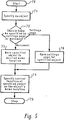
- Figure 5 is a high level flow chart depicting a specification of a home location for an object by a user in accordance with the present invention.
- the process starts as depicted at block 70 and thereafter passes to block 71 which illustrates the specification of an object.
- block 72 depicts a determination of whether or not a home location should bespecified by moving the specified object, or by opening a settings page associated with the specified object. If a determination is made to specify a home location by moving the specified object, the process passes to block 73 which depicts the movement of the specified object to a desired home location. Thereafter, the process passes to block 74 which illustrates the specification of the current location of the object as the object's home location. The process then terminates as illustrated at block 75.
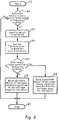
- Figure 6 is a high level flow chart illustrating the returning of an object to its specified home location or to a specified temporary location in accordance with the present invention.
- the process starts as depicted at block 78 and thereafter, passes to block 80 which illustrates a determination of whether or not a user desires to move an object to its home location. If a determination is made that a user desires to move an object to its home location, the process passes to block 82 which illustrates the specification of an object to be moved. Next, the process passes to block 84 which depicts the specification of "Return Home" in a menu for the specified object. Thereafter, the process passes to block 85 which illustrates a determination of whether or not a temporary location has been specified. If a temporary location has not been specified, the process passes to block 86 which depicts the movement of the specified object to the home location specified in the settings page for the object. Thereafter, the process terminates as depicted at block 87.
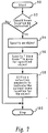
- Figure 7 is a high level flow chart depicting the indication of a home location for a specified object in accordance with the present invention.
- the process starts as depicted at block 90 and thereafter passes to block 92, which illustrates a determination of whether or not a home location should be visually indicated to a user utilizing the graphical user interface. If a determination is made that a home location should be indicated, the process passes to block 94 which illustrates the specification of an object. Next, the process passes to block 96 which depicts the specification of "Show Home" in a menu for the specified object. The process then passes to block 98 which illustrates a utilization of a selection emphasis to indicate the home location.
- a selection emphasis may include the displaying of a box around the container object which is the home location of the specified object. Thereafter, the process terminates as depicted at block 100. Referring again to block 92, if a determination is made that a home location should not be indicated, the process terminates again as depicted at block 100.
- Figure 8 is a high level flow chart illustrating a specification of a temporary location for a specified object in accordance with the present invention.
- the process starts as depicted at block 102 and thereafter passes to block 104 which illustrates a determination of whether or not a temporary location should be specified. If a determination is made that a temporary location should be specified, the process passes to block 106 which depicts the specification of an object. Next, the process passes to block 107 which illustrates a determination of whether or not a temporary location should be specified utilizing a settings page associated with the object, or by moving the object to the temporary location. If a determination is made that a temporary location should be specified by utilizing a settings page, the process passes to block 108 which illustrates the displaying of a settings page for the specified object. Thereafter, the process passes to block 109 which illustrates the specification of a temporary location within the settings page. The process then passes to block 112.
- the process passes to block 112 which illustrates a determination of whether or not a temporary location should be canceled. If a determination is made that a temporary location should be canceled, the process passes to block 114 which depicts the specification of an object. Thereafter, the process passes to block 115 which illustrates a determination of whether or not a temporary location should be cancelled utilizing a settings page associated with the specified object, or by moving the object to the temporary location to be cancelled. If a determination is made to cancel a temporary location utilizing a settings page, the process passes to block 116 which illustrates the displaying of a settings page for the specified object. Next, the process passes to block 117 which illustrates the canceling of the temporary location within the settings page of the specified object. The process then terminates as depicted at block 120.
- the process passes to block 118 which depicts the movement of the specified object to the temporary location. Thereafter, the process passes to block 117.
- the process again terminates as depicted at block 120.
- the process again terminates as depicted at block 120.
Abstract
Description
- The present invention relates in general to an improved graphical user interface in a data processing system and in particular to a method and system for the automatic storage of an object within a container object within a graphical user interface in a data processing system. Still more particularly, the present invention relates to a method and system for the automatic storage of an object within a container object within a graphical user interface in a data processing system in response to completion of utilization of the object.
- Data processing systems commonly utilize graphical user interfaces to enable users to interact with the data processing system and manipulate the activities and functions available to the users. Users may select, through the graphical user interface, a particular activity to perform utilizing input devices such as a keyboard or a "mouse." In a graphical user interface, activities such as "print document" or "select a document" may be represented to the user in the form of function keys graphically displayed on the computer display screen and selected by striking a particular key on the keyboard, or as icons to be selected utilizing a graphical pointing device such as a "mouse." A pointer, or mouse cursor, on the display screen is typically utilized to represent the current location of the "mouse." By moving the "mouse," a user may move the pointer, or mouse cursor, around within the computer display screen.
- An object may be graphically represented to a user as an "icon" utilizing the graphical user interface. An object is an item which may be manipulated as a unit. Objects may be of three types: device, data, or container. A device object may be manipulated to perform a selected task such as typically performed utilizing a physical or logical device such as a printer, mouse, or facsimile machine. For example, a "printer" device object may be manipulated to print documents or text. Data objects may include documents or text, such as created utilizing word processing applications. Container objects are typically objects into which other objects may be stored. Therefore, objects may be stored together in a container object and manipulated as a unit by manipulating the container object.
- Container objects, commonly called "folders," are typically provided as part of a graphical user interface. These "folders" may be iconically represented as a traditional filing folder and may be utilized to group, or "store," other objects in a way which is meaningful to a user. Such "folders" typically require a user to perform some action in order to select, locate and "store" objects within the "folder." Some known container objects may also be manipulated to perform user specified activities utilizing the objects stored within the container object. For example, a user may specify that all objects stored within a selected container object be printed.
- A graphical user interface may display multiple icons which represent objects. A user may utilize an object by positioning a mouse cursor over the icon representing the object, and clicking a mouse button to "open" the object. Once an object is opened, the contents of the object appear displayed in a window.
- A window is an area of the graphical user interface with visible boundaries within which information is displayed. Windows typically include a border completely surrounding the window, a status line indicating the name of the window or application being displayed in the window, various buttons to be utilized to maximize or minimize the size of the window, and pull-down menus which may be accessed by selecting a display element. Windows also typically appear in a color or shade different from the color or shade of the background of the graphical user interface in order to distinguish the window from the rest of the graphical user interface.
- Once an object is opened, a user may then utilize the object, such as by revising the text of an object created by a word processing application. Once a user has completed the utilization, the user may store the revisions and "close" the application at which time the window will disappear.
- A container object may be utilized to group objects. A user may utilize an object grouped within a container object by first "opening" the container object, viewing the contents of the container object, and then selecting and "opening" an object, as described above, stored within the container object. A user may utilize an object stored within a container object without actually removing the object from its container object. Once the user has completed utilization of the object, the user may "close" the object. When the object is closed, the window utilized to display the contents of the object will disappear, and the object remains stored in its container object throughout the utilization of the object.
- A user may desire to first remove an object from its container object before utilizing it. In this case, a user must first "open" a container object, and then select and remove the object from its container object. The object may then be utilized. Once the object is removed from its container object, it is no longer associated with the container object. Therefore, when the object is "closed," it is no longer stored in its original container object. Once the object is "closed," it is stored in its current location. Its current location may be in a different container object, or in the graphical user interface independently of any container object.
- It should therefore be apparent that a need exists for a method and system for the automatic storage of an object within a container object within a graphical user interface in a data processing system in response to completion of utilization of the object.
- It is therefore one objective of the present invention to provide an improved graphical user interface in a data processing system.
- It is another objective of the present invention to provide an improved method and system for the automatic storage of an object within a container object within a graphical user interface in a data processing system.
- It is yet another objective of the present invention to provide an improved method and system for the automatic storage of an object within a container object within a graphical user interface in a data processing system in response to a completion of utilization of the object.
- The foregoing objectives are achieved as is now described. A method and system are disclosed for the automatic storage of an object within a container object within a graphical user interface within a data processing system. A display, included within the data processing system, is utilized to display an iconic representation of a container object which is a graphic indication of a storage of objects. An object and a container object within the graphical user interface are specified. The object is thereafter associated with the container object. During utilization the object is removed from the container object. The object is then automatically stored within the container object in response to a completion of the utilization, wherein the organization of objects within the container object and the graphical user interface are enhanced.
-
- Figure 1 depicts a pictorial representation of a data processing system which may be utilized to implement the method and system of the present invention;
- Figure 2 illustrates a graphical user interface including an object and a setting's page of the object, wherein a home location may be specified in accordance with the present invention;
- Figure 3 depicts a graphical user interface including an object and an indication that the object is being returned to its home location in accordance with the present invention;
- Figure 4 illustrates a graphical user interface including an object and an indication of the home location of the object in accordance with the present invention;
- Figure 5 is a high level flow chart depicting a specification of a home location for an object in accordance with the present invention;
- Figure 6 is a high level flow chart illustrating the returning of an object to its specified home location in accordance with the present invention;
- Figure 7 is a high level flow chart depicting the indication of the home location for a specified object in accordance with the present invention; and
- Figure 8 is a high level flow chart illustrating a specification of a temporary location for a specified object in accordance with the present invention.
- An embodiment of the present invention will now be described with initial reference to Figure 1, which illustrates a representative
data processing system 10 in which the present invention may be practiced.Data processing system 10 includes a central processing unit (CPU) 8, which may be the processor of a host computer or the microprocessor of a work station or personal computer or the like. In any case, known means, such as abus 12, are employed to connect theCPU 8 to one or more interface devices, such askeyboard 16, amouse 18, and/orother interface devices 21a and 21b, which can be any user interface device, such as a touch sensitive screen, a digitized pen entry pad, etc. Adisplay device 20, such as an LCD screen or CRT screen, is connected toCPU 8 via adisplay adapter 24.CPU 8 is also connected tomemory 26, which can include ROM, RAM, etc. In a preferred embodiment of the present invention,CPU 8 is suitably programmed to implement the logic flow charts of Figures 5 through 8 in order to provide automatic storage of an object within a container object in a graphical user interface in a data processing system. - Figure 2 illustrates a graphical user interface including an object and a setting's page of the object, wherein a home location may be specified in accordance with the present invention. An object may be graphically represented to a user as an "icon" utilizing the graphical user interface. An object is an item which may be manipulated as a unit. Those skilled in the art should appreciate that a user may manipulate either an object or an icon representing the object to achieve the same result. Container objects are typically objects into which other objects may be stored. Therefore, objects may be stored together in a container object and manipulated as a unit by manipulating the container object.
- A
container object 32 is displayed within graphical user interface 30 and may be utilized to group related objects. For example,container object 32 may be utilized to group objects associated with the days of October. Anobject 34 has been removed fromcontainer object 32 and opened to display the contents ofobject 34.Other icons - A user may remove
object 34 fromcontainer object 32 in order to utilize it. In known systems, once a user has completed utilizingobject 34, the user must remember the home location forobject 34, and must physically returnobject 34 to its home. Those skilled in the art should appreciate that either an object, or an icon representing an object, may be manipulated, such as by removal, and returned to a container object. - In accordance with the present invention, a home location for
object 34 may be specified inhome location field 48 within asettings page 46 ofobject 34. A settings page associated with each object is utilized to define characteristics of the object, such as object name, security level, creation and modification dates. - When the user has completed utilization of
object 34,object 34 may be automatically returned to its specified home location, or a temporary location, if one is specified. A temporary location may be specified intemporary location field 50 withinsettings page 46. - Figure 3 depicts a graphical user interface including an object and an indication that the object is being returned to its home location in accordance with the present invention.
Icon 52 representsobject 34. A user may select "Return Home" inmenu 54 in order to returnobject 34 to its specified home location,container object 32. An arrow is displayed in Figure 3 for illustrative purposes to indicateobject 34, represented asicon 52, being returned tocontainer object 32. - Figure 4 illustrates a graphical user interface including an object and an indication of the home location of the object in accordance with the present invention. A user may wish to determine the home location to which an object may return without actually having the object return to its home location. A user may select "Show Home" in
menu 54 associated withobject 34 represented byicon 52. A selection emphasis, such as the displaying of a box around the container object which is the specified home location, is then displayed to indicate the specified home location forobject 34. - Figure 5 is a high level flow chart depicting a specification of a home location for an object by a user in accordance with the present invention. The process starts as depicted at
block 70 and thereafter passes to block 71 which illustrates the specification of an object. Next, the process passes to block 72 which depicts a determination of whether or not a home location should bespecified by moving the specified object, or by opening a settings page associated with the specified object. If a determination is made to specify a home location by moving the specified object, the process passes to block 73 which depicts the movement of the specified object to a desired home location. Thereafter, the process passes to block 74 which illustrates the specification of the current location of the object as the object's home location. The process then terminates as illustrated atblock 75. - Referring again to block 72, if a determination is made to specify a home location by opening a settings page, the process passes to block 76 which illustrates the opening of a settings page associated with the specified object. The process again passes to block 74.
- Figure 6 is a high level flow chart illustrating the returning of an object to its specified home location or to a specified temporary location in accordance with the present invention. The process starts as depicted at
block 78 and thereafter, passes to block 80 which illustrates a determination of whether or not a user desires to move an object to its home location. If a determination is made that a user desires to move an object to its home location, the process passes to block 82 which illustrates the specification of an object to be moved. Next, the process passes to block 84 which depicts the specification of "Return Home" in a menu for the specified object. Thereafter, the process passes to block 85 which illustrates a determination of whether or not a temporary location has been specified. If a temporary location has not been specified, the process passes to block 86 which depicts the movement of the specified object to the home location specified in the settings page for the object. Thereafter, the process terminates as depicted atblock 87. - Referring again to block 85, if a determination is made that the object does have a specified temporary location, the processes passes to block 88 which illustrates the movement of the object to the specified temporary location. The process then terminates as depicted at
block 87. Referring again to block 80, if a determination is made that a user does not desire to move an object to its home location, the process terminates again as depicted atblock 87. - Figure 7 is a high level flow chart depicting the indication of a home location for a specified object in accordance with the present invention. The process starts as depicted at
block 90 and thereafter passes to block 92, which illustrates a determination of whether or not a home location should be visually indicated to a user utilizing the graphical user interface. If a determination is made that a home location should be indicated, the process passes to block 94 which illustrates the specification of an object. Next, the process passes to block 96 which depicts the specification of "Show Home" in a menu for the specified object. The process then passes to block 98 which illustrates a utilization of a selection emphasis to indicate the home location. For example, a selection emphasis may include the displaying of a box around the container object which is the home location of the specified object. Thereafter, the process terminates as depicted atblock 100. Referring again to block 92, if a determination is made that a home location should not be indicated, the process terminates again as depicted atblock 100. - Figure 8 is a high level flow chart illustrating a specification of a temporary location for a specified object in accordance with the present invention. The process starts as depicted at block 102 and thereafter passes to block 104 which illustrates a determination of whether or not a temporary location should be specified. If a determination is made that a temporary location should be specified, the process passes to block 106 which depicts the specification of an object. Next, the process passes to block 107 which illustrates a determination of whether or not a temporary location should be specified utilizing a settings page associated with the object, or by moving the object to the temporary location. If a determination is made that a temporary location should be specified by utilizing a settings page, the process passes to block 108 which illustrates the displaying of a settings page for the specified object. Thereafter, the process passes to block 109 which illustrates the specification of a temporary location within the settings page. The process then passes to block 112.
- Referring again to block 107, if a determination is made to specify a temporary location by moving the specified object, the process passes to block 110 which depicts the movement of the specified object to a temporary location. The process then again passes to block 109.
- Next, the process passes to block 112 which illustrates a determination of whether or not a temporary location should be canceled. If a determination is made that a temporary location should be canceled, the process passes to block 114 which depicts the specification of an object. Thereafter, the process passes to block 115 which illustrates a determination of whether or not a temporary location should be cancelled utilizing a settings page associated with the specified object, or by moving the object to the temporary location to be cancelled. If a determination is made to cancel a temporary location utilizing a settings page, the process passes to block 116 which illustrates the displaying of a settings page for the specified object. Next, the process passes to block 117 which illustrates the canceling of the temporary location within the settings page of the specified object. The process then terminates as depicted at
block 120. - Referring again to block 115, if a determination is made to cancel a temporary location by moving the specified object, the process passes to block 118 which depicts the movement of the specified object to the temporary location. Thereafter, the process passes to block 117. Referring again to block 104, if a determination is made that a temporary location should not be specified, the process again terminates as depicted at
block 120. Referring again to block 112, if a determination is made that a temporary location should not be canceled, the process again terminates as depicted atblock 120.
Claims (6)
- In a data processing system including a graphical user interface a method for automatically storing an object within a container object within said data processing system, said data processing system including a display for displaying an iconic representation of said container object, wherein said container object is a graphic object which may be removed from said container object for utilization, said method comprising the data processing system implemented steps of:
specifying an object within said graphical user interface;
specifying a container object within said graphical user interface;
associating said object with said container object;
removing said object from said container object for utilization; and
automatically storing said object within said container object in response to completion of said utilization of said object, wherein organization of said objects within said container object is enhanced. - In a data processing system including a graphical user interface a method for automatically storing an object within a container object within said data processing system according to Claim 1, wherein said graphical user interface includes a plurality of container objects, further comprising the steps of:
determining if a temporary relationship between said object and a second of said plurality of container objects has been specified; and
thereafter, automatically storing said object within said second of said plurality of container objects in response to a determination that said temporary relationship between said object and a second of said plurality of container objects has been specified. - In a data processing system including a graphical user interface a method for automatically storing an object within a container object within said data processing system according to Claim 1 OR 2, further comprising a step of displaying an indication of said container object in response to a utilization of said object.
- A data processing system including a graphical user interface for automatically storing an object within a container object within said data processing system, said data processing system including a display for displaying an iconic representation of said container object, wherein said container object is a graphic object which may be removed from said container object for utilization, comprising:
means for specifying an object within said graphical user interface;
means for specifying a container object within said graphical user interface;
means for associating said object with said container object;
means for removing said object from said container object for utilization; and
means for automatically storing said object within said container object in response to completion of said utilization of said object, wherein organization of said objects within said container object is enhanced. - A data processing system including a graphical user interface for automatically storing an object within a container object within said data processing system according to Claim 4, wherein said graphical user interface includes a plurality of container objects, further comprising:
means for determining if a temporary relationship between said object and a second of said plurality of container objects has been specified; and
means for thereafter, automatically storing said object within said second of said plurality of container objects in response to a determination that said temporary relationship between said object and a second of said plurality of container objects has been specified. - A data processing system including a graphical user interface for automatically storing an object within a container object within said data processing system according to Claim 4 or 5, means for displaying an indication of said container object in response to a utilization of said object.
Applications Claiming Priority (2)
| Application Number | Priority Date | Filing Date | Title |
|---|---|---|---|
| US160623 | 1988-02-26 | ||
| US08/160,623 US5619637A (en) | 1993-12-02 | 1993-12-02 | Method and system for automatic storage of an object within a container object within a graphical user interface within a data processing system |
Publications (3)
| Publication Number | Publication Date |
|---|---|
| EP0656580A2 true EP0656580A2 (en) | 1995-06-07 |
| EP0656580A3 EP0656580A3 (en) | 1998-12-30 |
| EP0656580B1 EP0656580B1 (en) | 2002-01-23 |
Family
ID=22577667
Family Applications (1)
| Application Number | Title | Priority Date | Filing Date |
|---|---|---|---|
| EP94480120A Expired - Lifetime EP0656580B1 (en) | 1993-12-02 | 1994-11-08 | Method and system for automatic storage of an object within a container object within a graphical user interface within a data processing system |
Country Status (4)
| Country | Link |
|---|---|
| US (1) | US5619637A (en) |
| EP (1) | EP0656580B1 (en) |
| JP (1) | JPH07200244A (en) |
| DE (1) | DE69429711T2 (en) |
Cited By (2)
| Publication number | Priority date | Publication date | Assignee | Title |
|---|---|---|---|---|
| GB2324450A (en) * | 1997-04-19 | 1998-10-21 | Ibm | Graphical user interface |
| US7827483B2 (en) * | 1998-08-28 | 2010-11-02 | Corel Corporation | Real time preview |
Families Citing this family (14)
| Publication number | Priority date | Publication date | Assignee | Title |
|---|---|---|---|---|
| US5862372A (en) * | 1994-11-16 | 1999-01-19 | Morris; Robert M. | Visually oriented computer implemented application development system utilizing standardized objects and multiple views |
| US6222542B1 (en) | 1995-10-10 | 2001-04-24 | Anysoft, Ltd | Apparatus for and method of acquiring, processing and routing data contained in a GUI window |
| US5903269A (en) * | 1995-10-10 | 1999-05-11 | Anysoft Ltd. | Apparatus for and method of acquiring processing and routing data contained in a GUI window |
| US5889518A (en) * | 1995-10-10 | 1999-03-30 | Anysoft Ltd. | Apparatus for and method of acquiring, processing and routing data contained in a GUI window |
| US5784061A (en) * | 1996-06-26 | 1998-07-21 | Xerox Corporation | Method and apparatus for collapsing and expanding selected regions on a work space of a computer controlled display system |
| US5936624A (en) * | 1997-03-07 | 1999-08-10 | International Business Machines Corporation | Data processing system having a logical containment system and method therefor |
| KR100320297B1 (en) | 1998-11-04 | 2002-04-22 | 오길록 | Virtual Space Navigation Interface Method Using Body Icons |
| US20040109025A1 (en) * | 2002-08-28 | 2004-06-10 | Jean-Marie Hullot | Computer program comprising a plurality of calendars |
| EP1546972A1 (en) * | 2002-09-09 | 2005-06-29 | Apple Computer, Inc. | A computer program comprising a plurality of calendars |
| EP1546846A2 (en) * | 2002-09-09 | 2005-06-29 | Apple Computer, Inc. | A method of managing a calendar and a computer system for implementing that method |
| US7991637B1 (en) | 2004-05-24 | 2011-08-02 | Apple Inc. | Freeform communication in calendaring system |
| WO2006034218A2 (en) * | 2004-09-20 | 2006-03-30 | On A Chart, Llc | Electronic file system graphical user interface |
| JP4560395B2 (en) * | 2004-12-13 | 2010-10-13 | 株式会社リコー | Image forming apparatus |
| US8959452B2 (en) * | 2011-10-11 | 2015-02-17 | Texas Instruments Incorporated | Method, system and computer program product for receiving information from a user |
Citations (8)
| Publication number | Priority date | Publication date | Assignee | Title |
|---|---|---|---|---|
| EP0339220A2 (en) * | 1988-04-25 | 1989-11-02 | Hewlett-Packard Company | File management system for a computer |
| EP0343882A2 (en) * | 1988-05-23 | 1989-11-29 | Hewlett-Packard Company | A computer system and method adapted for task automation and instruction delivery |
| WO1989011694A1 (en) * | 1988-05-27 | 1989-11-30 | Wang Laboratories, Inc. | Document folder icon for display in a data processing system |
| EP0415796A2 (en) * | 1989-08-31 | 1991-03-06 | Xerox Corporation | Graphics user interface |
| US5072412A (en) * | 1987-03-25 | 1991-12-10 | Xerox Corporation | User interface with multiple workspaces for sharing display system objects |
| WO1992008199A1 (en) * | 1990-10-31 | 1992-05-14 | Go Corporation | Computer documents as compound documents in a notebook metaphor |
| EP0520924A2 (en) * | 1991-06-28 | 1992-12-30 | International Business Machines Corporation | Container object management system |
| EP0530122A1 (en) * | 1991-08-30 | 1993-03-03 | International Business Machines Corporation | System and graphical method for creating an object |
Family Cites Families (1)
| Publication number | Priority date | Publication date | Assignee | Title |
|---|---|---|---|---|
| JPH04312140A (en) * | 1991-04-11 | 1992-11-04 | Matsushita Electric Ind Co Ltd | File controller |
-
1993
- 1993-12-02 US US08/160,623 patent/US5619637A/en not_active Expired - Fee Related
-
1994
- 1994-09-21 JP JP6226208A patent/JPH07200244A/en active Pending
- 1994-11-08 DE DE69429711T patent/DE69429711T2/en not_active Expired - Lifetime
- 1994-11-08 EP EP94480120A patent/EP0656580B1/en not_active Expired - Lifetime
Patent Citations (8)
| Publication number | Priority date | Publication date | Assignee | Title |
|---|---|---|---|---|
| US5072412A (en) * | 1987-03-25 | 1991-12-10 | Xerox Corporation | User interface with multiple workspaces for sharing display system objects |
| EP0339220A2 (en) * | 1988-04-25 | 1989-11-02 | Hewlett-Packard Company | File management system for a computer |
| EP0343882A2 (en) * | 1988-05-23 | 1989-11-29 | Hewlett-Packard Company | A computer system and method adapted for task automation and instruction delivery |
| WO1989011694A1 (en) * | 1988-05-27 | 1989-11-30 | Wang Laboratories, Inc. | Document folder icon for display in a data processing system |
| EP0415796A2 (en) * | 1989-08-31 | 1991-03-06 | Xerox Corporation | Graphics user interface |
| WO1992008199A1 (en) * | 1990-10-31 | 1992-05-14 | Go Corporation | Computer documents as compound documents in a notebook metaphor |
| EP0520924A2 (en) * | 1991-06-28 | 1992-12-30 | International Business Machines Corporation | Container object management system |
| EP0530122A1 (en) * | 1991-08-30 | 1993-03-03 | International Business Machines Corporation | System and graphical method for creating an object |
Non-Patent Citations (1)
| Title |
|---|
| "DESKTOP COMPASS" IBM TECHNICAL DISCLOSURE BULLETIN, vol. 36, no. 8, 1 August 1993, pages 337-338, XP000390245 * |
Cited By (4)
| Publication number | Priority date | Publication date | Assignee | Title |
|---|---|---|---|---|
| GB2324450A (en) * | 1997-04-19 | 1998-10-21 | Ibm | Graphical user interface |
| US7827483B2 (en) * | 1998-08-28 | 2010-11-02 | Corel Corporation | Real time preview |
| US8700996B2 (en) | 1998-08-28 | 2014-04-15 | Corel Corporation | Real time preview |
| US9092119B2 (en) | 1998-08-28 | 2015-07-28 | Corel Software LLC | Real time preview |
Also Published As
| Publication number | Publication date |
|---|---|
| JPH07200244A (en) | 1995-08-04 |
| US5619637A (en) | 1997-04-08 |
| EP0656580B1 (en) | 2002-01-23 |
| EP0656580A3 (en) | 1998-12-30 |
| DE69429711D1 (en) | 2002-03-14 |
| DE69429711T2 (en) | 2002-09-12 |
Similar Documents
| Publication | Publication Date | Title |
|---|---|---|
| US5550969A (en) | Graphical method of indicating the position of and performing an operation on a plurality of selected objects in a computer system | |
| US5664128A (en) | Object storage apparatus for use with data sets in computer applications | |
| US5704050A (en) | Snap control for relocating elements of a graphical user interface | |
| EP0656580B1 (en) | Method and system for automatic storage of an object within a container object within a graphical user interface within a data processing system | |
| US5872568A (en) | Application and method for creating a list from pre-defined and user values | |
| US5721847A (en) | Method and system for linking controls with cells of a spreadsheet | |
| US5416901A (en) | Method and apparatus for facilitating direct icon manipulation operations in a data processing system | |
| US5140677A (en) | Computer user interface with window title bar mini-icons | |
| US5491783A (en) | Method and apparatus for facilitating integrated icon-based operations in a data processing system | |
| EP0557346B1 (en) | Electronic display and data processing apparatus | |
| US5345550A (en) | User-modifiable popup menus for object oriented behavior | |
| US5065347A (en) | Hierarchical folders display | |
| US5812862A (en) | Computer-human interface system for compound documents | |
| EP0661621B1 (en) | Graphical user interface which supports data transfer between one source and a plurality of target objects | |
| US5847707A (en) | Icon menu display devices and methods | |
| EP0647899A1 (en) | Method and apparatus for preventing unintentional perusal of computer display information | |
| US20020091739A1 (en) | Systems and methods for manipulating electronic information using a three-dimensional iconic representation | |
| EP0662655A2 (en) | Method and system for customizing a data processing system graphical user interface | |
| JPH07210393A (en) | Method and equipment for creation of rule for data processing system | |
| US5781193A (en) | Graphical interface method, apparatus and application for creating multiple value list from superset list | |
| WO1996039655A1 (en) | A data processing system | |
| US6104395A (en) | Graphical interface method, apparatus and application for opening window of all designated container objects | |
| US5796383A (en) | Method and system for presenting contents of a container object within a graphical user interface in a data processing system | |
| US6054988A (en) | Expand to wells function in graphical user interface system | |
| US5867157A (en) | Graphical interface method, apparatus and application for creating and modifying a list of values with multiple components |
Legal Events
| Date | Code | Title | Description |
|---|---|---|---|
| PUAI | Public reference made under article 153(3) epc to a published international application that has entered the european phase |
Free format text: ORIGINAL CODE: 0009012 |
|
| AK | Designated contracting states |
Kind code of ref document: A2 Designated state(s): DE FR GB |
|
| 17P | Request for examination filed |
Effective date: 19951024 |
|
| PUAL | Search report despatched |
Free format text: ORIGINAL CODE: 0009013 |
|
| AK | Designated contracting states |
Kind code of ref document: A3 Designated state(s): DE FR GB |
|
| GRAG | Despatch of communication of intention to grant |
Free format text: ORIGINAL CODE: EPIDOS AGRA |
|
| 17Q | First examination report despatched |
Effective date: 20010308 |
|
| GRAG | Despatch of communication of intention to grant |
Free format text: ORIGINAL CODE: EPIDOS AGRA |
|
| GRAH | Despatch of communication of intention to grant a patent |
Free format text: ORIGINAL CODE: EPIDOS IGRA |
|
| GRAH | Despatch of communication of intention to grant a patent |
Free format text: ORIGINAL CODE: EPIDOS IGRA |
|
| GRAA | (expected) grant |
Free format text: ORIGINAL CODE: 0009210 |
|
| REG | Reference to a national code |
Ref country code: GB Ref legal event code: IF02 |
|
| AK | Designated contracting states |
Kind code of ref document: B1 Designated state(s): DE FR GB |
|
| REF | Corresponds to: |
Ref document number: 69429711 Country of ref document: DE Date of ref document: 20020314 |
|
| ET | Fr: translation filed | ||
| PLBE | No opposition filed within time limit |
Free format text: ORIGINAL CODE: 0009261 |
|
| STAA | Information on the status of an ep patent application or granted ep patent |
Free format text: STATUS: NO OPPOSITION FILED WITHIN TIME LIMIT |
|
| 26N | No opposition filed | ||
| REG | Reference to a national code |
Ref country code: GB Ref legal event code: 746 Effective date: 20071007 |
|
| PGFP | Annual fee paid to national office [announced via postgrant information from national office to epo] |
Ref country code: DE Payment date: 20091120 Year of fee payment: 16 |
|
| PGFP | Annual fee paid to national office [announced via postgrant information from national office to epo] |
Ref country code: FR Payment date: 20101203 Year of fee payment: 17 |
|
| PGFP | Annual fee paid to national office [announced via postgrant information from national office to epo] |
Ref country code: GB Payment date: 20101126 Year of fee payment: 17 |
|
| REG | Reference to a national code |
Ref country code: DE Ref legal event code: R119 Ref document number: 69429711 Country of ref document: DE Effective date: 20110601 Ref country code: DE Ref legal event code: R119 Ref document number: 69429711 Country of ref document: DE Effective date: 20110531 |
|
| PG25 | Lapsed in a contracting state [announced via postgrant information from national office to epo] |
Ref country code: DE Free format text: LAPSE BECAUSE OF NON-PAYMENT OF DUE FEES Effective date: 20110531 |
|
| GBPC | Gb: european patent ceased through non-payment of renewal fee |
Effective date: 20111108 |
|
| REG | Reference to a national code |
Ref country code: FR Ref legal event code: ST Effective date: 20120731 |
|
| PG25 | Lapsed in a contracting state [announced via postgrant information from national office to epo] |
Ref country code: GB Free format text: LAPSE BECAUSE OF NON-PAYMENT OF DUE FEES Effective date: 20111108 |
|
| PG25 | Lapsed in a contracting state [announced via postgrant information from national office to epo] |
Ref country code: FR Free format text: LAPSE BECAUSE OF NON-PAYMENT OF DUE FEES Effective date: 20111130 |