EP0658859A2 - Method and apparatus for interlocking graphical objects - Google Patents
Method and apparatus for interlocking graphical objects Download PDFInfo
- Publication number
- EP0658859A2 EP0658859A2 EP94307336A EP94307336A EP0658859A2 EP 0658859 A2 EP0658859 A2 EP 0658859A2 EP 94307336 A EP94307336 A EP 94307336A EP 94307336 A EP94307336 A EP 94307336A EP 0658859 A2 EP0658859 A2 EP 0658859A2
- Authority
- EP
- European Patent Office
- Prior art keywords
- graphical object
- moved
- displayed
- graphical
- graphics
- Prior art date
- Legal status (The legal status is an assumption and is not a legal conclusion. Google has not performed a legal analysis and makes no representation as to the accuracy of the status listed.)
- Granted
Links
Images


Classifications
-
- G—PHYSICS
- G06—COMPUTING; CALCULATING OR COUNTING
- G06T—IMAGE DATA PROCESSING OR GENERATION, IN GENERAL
- G06T17/00—Three dimensional [3D] modelling, e.g. data description of 3D objects
-
- G—PHYSICS
- G06—COMPUTING; CALCULATING OR COUNTING
- G06T—IMAGE DATA PROCESSING OR GENERATION, IN GENERAL
- G06T15/00—3D [Three Dimensional] image rendering
- G06T15/10—Geometric effects
- G06T15/40—Hidden part removal
-
- G—PHYSICS
- G06—COMPUTING; CALCULATING OR COUNTING
- G06F—ELECTRIC DIGITAL DATA PROCESSING
- G06F3/00—Input arrangements for transferring data to be processed into a form capable of being handled by the computer; Output arrangements for transferring data from processing unit to output unit, e.g. interface arrangements
- G06F3/14—Digital output to display device ; Cooperation and interconnection of the display device with other functional units
Definitions
- the present invention relates to a method and apparatus for interlocking graphical objects in a computer graphics system.
- a two dimensional display In computer graphics systems, it is desired to represent two and three dimensional graphical picture on a two dimensional display.
- a picture is a construct or image that may be stored in memory as a set of polygons.
- the polygons are then rendered using processes that are typically computationally intensive.
- a portion of the picture to be represented may fall outside the field of vision provided by a window on the display or by the display itself. In such cases, it may be desirable to clip the picture and the polygons comprising the picture as the picture is being generated, thereby reducing computational requirements and increasing rendering speed.
- a polygon is typically specified as a set of vertices P(0), P(1), ..., P(n-2), P(n-1), where n is the number of vertices in the polygon.
- Each vertex P(i) is specified by its location V(i) in a suitable coordinate space and a function, referred to herein as a color factor, f(V(i)).
- a color factor is a function evaluated at each vertex that may be displayed later as a color (including a grayscale) variation (such as a light intensity, a thermal characteristic, a humidity factor, etc.). The color factor may be converted to a color and is useful in modelling (such as simple lighting modelling or more complex weather modelling).
- typical two dimensional graphics systems allow the user to pick and drag polygons to desired locations.
- a polygon is picked when the user selects that object, typically by positioning a cursor over the object and pressing a mouse button.
- the object is dragged by the user moving the cursor, typically by moving the mouse while continuing to press the mouse button.
- an object being dragged is shown in outline form during the dragging operation to reduce computational requirements of rendering the object as the object is moved.
- the user may then drop the object, typically by releasing the mouse button.
- Prior art systems then render the polygon in the drop location. If there are any pre-existing objects that are also at the same location, then the dropped object is rendered as being on top of the pre-existing object. If the user desires the pre-existing object to be on top of the dropped object, then the user must pick the pre-existing object and then drop it without dragging the object anywhere. This results in the pre-existing object being placed on top of the just dragged object.
- apparatus for moving graphical objects comprising: a display for displaying a plurality of graphical objects according to a display priority; means for moving, responsive to a user input, a displayed graphical object; and means for modifying, responsive to a user input, a display priority of the moved graphical object as the graphical object is moved so that the moved graphical object is displayed under a portion of a second displayed graphical object.
- a method for moving graphical objects comprising: displaying a plurality of graphical objects according to a display priority on a display; moving, responsive to a user input, a displayed graphical object; and modifying, responsive to a user input, a display priority of the moved graphical object as the graphical object is moved so that the moved graphical object is displayed under a portion of a second displayed graphical object.
- This disclosure describes an improved method and apparatus for interlocking objects, particularly in two dimensional environments.
- the user may drag a graphical object above, below, or both above and below (interlocking) another graphical object.
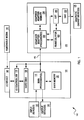
- Fig. 1 is a block diagram of a typical digital computer 100 utilized by a preferred embodiment of the invention.
- the computer includes main processor(s) 110 coupled to a memory 120 and a hard disk 125 in computer box 105 with input device(s) 130 and output device(s) 140 attached.
- Main processor(s) 110 may include a single processor or multiple processors.
- Input device(s) 130 may include a keyboard, mouse, tablet or other types of input devices.
- Output device(s) 140 may include a text monitor, plotter or other types of output devices.
- Computer readable removable media 190 such as a magnetic diskette or a compact disc, may be inserted into an input/output device 180, such as a disk drive or a CD-ROM (compact disc - read only memory) drive.
- Data is read from or written to the removable media by the I/O device under the control of the I/O device controller 170.
- the I/O device controller communicates with the main processor through across bus 160.
- Main memory 120, hard disk 125 and removable media 190 are all referred to as memory for storing data for processing by main processor(s) 110.
- the main processor may also be coupled to graphics output device(s) 150 such as a graphics display through a graphics adapter 200.
- Graphics adapter 200 receives instructions regarding graphics from main processor(s) 110 on bus 160. The graphics adapter then executes those instructions with graphics adapter processor(s) 220 coupled to a graphics adapter memory 230. The graphics processors in the graphics adapter then execute those instructions and updates frame buffer(s) 240 based on those instructions.
- Graphic processors 220 may also include specialized rendering hardware for rendering specific types of primitives.
- Frame buffer(s) 240 includes data for every pixel to be displayed on the graphics output device.
- a RAMDAC (random access memory digital-to-analog converter) 250 converts the digital data stored in the frame buffers into RGB signals to be provided to the graphics display 150 thereby rendering the desired graphics output from the main processor.
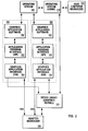
- Fig. 2 is a block diagram illustrating the layers of code typically utilized by the host computer and graphics adapter to perform graphics functions.
- An operating system 300 such as UNIX provides the primary control of the host computer. Coupled to the operating system is an operating system kernel 310 which provides the hardware intensive tasks for the operating system. The operating system kernel communicates directly with the host computer microcode 320. The host computer microcode is the primary instruction set executed by the host computer processor. Coupled to the operating system 300 are graphics applications 330 and 332.
- This graphics application software can include software packages such as Silicon Graphic's GL, IBM's graPHIGS, MIT's PEX, etc. This software provides the primary functions of two dimensional or three dimensional graphics.
- Graphics applications 330 and 332 are coupled to graphics application API (application program interface) 340 and 342, respectively.
- the API provides many of the computationally intensive tasks for the graphics application and provides an interface between the application software and software closer to the graphics hardware such as a device driver for the graphics adapter.
- API 340 and 342 may communicate with a GAI (graphics application interface) 350 and 352, respectively.
- GAI graphics application interface
- the GAI provides an interface between the application API and a graphics adapter device driver 370.
- the API also performs the function of the GAI.
- the graphics application, API, and GAI are considered by the operating system and the device driver to be a single process. That is, graphics applications 330 and 332, API 340 and 342, and GAI 350 and 352 are considered by operating system 300 and device driver 370 to be processes 360 and 362, respectively.
- the processes are identified by the operating system and the device driver by a process identifier (PID) that is assigned to the process by the operating system kernel.
- PID process identifier
- Processes 360 and 362 may use the same code that is being executed twice simultaneously, such as two executions of a program in two separate windows. The PID is used to distinguish the separate executions of the same code.
- the device driver is a graphics kernel which is an extension of the operating system kernel 310.
- the graphics kernel communicates directly with microcode of the graphics adapter 380.
- the GAI or the API if no GAI layer is used, may request direct access from the GAI or API to the adapter microcode by sending an initial request instruction to the device driver.
- many graphics systems also allow the adapter microcode to request direct access from the adapter microcode to the GAI or API if no GAI is used by sending an initial request instruction to the device driver. Both processes will hereinafter be referred to as direct memory access (DMA).
- DMA direct memory access
- the DMA provides for a quicker transmission of data between the host computer and the adapter by eliminating the need to go through the display driver other than the initial request for the device driver to set up the DMA.
- the adapter microcode utilizes context switching which allows the adapter microcode to replace the current attributes being utilized by the adapter microcode. Context switching is used when the adapter microcode is to receive an instruction from a graphics application that utilizes different attributes than the adapted microcode is currently using. The context switch is typically initiated by the device driver which recognizes the attribute changes.
- Blocks 300-340 are software code layers that are typically independent of the type of graphics adapter being utilized.
- Blocks 350-380 are software code layers that are typically dependent upon the type of graphics adapter being utilized. For example, if a different graphics adapter were to be used by the graphics application software, then a new GAI, graphics kernel and adapter microcode would be needed.
- blocks 300-370 typically reside on and are executed by the host computer.
- the adapter microcode 380 typically resides on and is executed by the graphics adapter. However, in some cases, the adapter microcode is loaded into the graphics adapter by the host computer during initialization of the graphics adapter.
- the user instructs the graphics application to construct an image from a two or three dimensional model.
- the user first selects the location and type of light sources.
- the user then instructs the application software to build the desired model from a set of predefined or user defined objects.
- Each object may include one or more coplanar drawing primitives describing the object. For example, a set of drawing primitives such as many triangles may be used to define the surface of an object.
- the user then provides a perspective in a window to view the model, thereby defining the desired image.
- the application software then starts the rendering of the image from the model by sending the drawing primitives describing the objects to the adapter microcode through the API, the GAI, and then the device driver unless DMA is used.
- the adapter microcode then renders the image on the graphics display by clipping (i.e. not using) those drawing primitives not visible in the window and the adapter microcode breaks each remaining drawing primitive into visible pixels from the perspective given by the user.
- the pixels are then loaded into the frame buffer, often with the use of a depth buffer in the case of a three dimensional model. This step is very computationally intensive due to the number of drawing primitives, variables, and pixels involved.
- the resulting image stored in the frame buffer and displayed on the graphics display typically does not carry the original information such as which drawing primitive or object the pixel was derived from. As a result, the image may need to be rerendered in part or in whole if the window, the user perspective, the model, the lighting, etc. are modified.
- the dragging technique could be utilized in many locations such as the adapter microcode which is close to the adapter frame buffer. This approach would also be relatively quick and fairly easy to implement.
- the dragging technique could be applied in the graphics application software wherein the rendered image is also stored in system memory either prior to the image being rendered or subsequently by the graphics adapter passing the data back up to the graphics application software. This approach would be much slower but would allow for utilization of this technique on preexisting graphics adapters.
- the dragging technique could also be implemented in hardware in the graphics adapter processor. This approach is extremely quick but may necessitate specialized hardware. This would allow for rapid clipping of primitives to be displayed by the graphics adapter. As would be obvious to one of ordinary skill in the art, the present technique would be applied in many other locations within the host computer or graphics adapter.
- the polygon can be convex or concave.
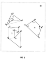
- Fig. 3 illustrates several polygons including convex and concave polygons on a display 400.
- Polygons A and C are concave polygons while polygon B is a convex polygon.
- Each of the polygons is defined by a series of vertices which are interconnected by edges.
- a polygon is concave if there exists a vertex, such as vertex A1, that can be covered by the polygon when that vertex is removed from the polygon.
- a polygon may also be defined to be concave if the interior angle of the edges for any vertices is greater than 180 degrees. For example, in polygon B which is convex, all the interior angles at vertices are less than 180 degrees. However, the interior angle will at vertex A1 of polygon A is greater than 180 degrees.
- any concave polygon can be divided into a set of convex polygons by connecting each concave point to another vertex of the polygon such that each of the polygon parts is convex.
- the polygon can be divided into three convex polygons by dividing the polygon from vertex C4 to vertex C7 and from vertex C3 to vertex C8.
- the polygon C could also be divided from vertex C4 to vertex C6 and from vertex C3 to vertex C1 and from vertex C3 to vertex C7.
- all polygons could be broken into a set of triangles without determining whether the polygon is concave are convex. This would insure that all concave polygons are divided into a set of convex polygons.
- the dragged object when an object is dragged over another object, can either dragged on top of the stationary object, below the stationary object, or some combination of above and below the stationary object called an interlock.
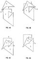
- Figs. 4A-4D illustrate dragging object C of Fig. 3 across object A of Fig 3.
- Fig. 4A illustrates object C colliding with object A at vertex C7.
- the user designates whether object C would be dragged under or over object A.
- the user selects object C to be dragged under object A for this collision.
- Fig. 4B illustrates object C being dragged under object A until a second point, vertex C2, collides with object A.
- the user selects whether this part of object C will be dragged under or over object A.
- the user selects that this part of object C will pass over object A.
- Fig. 4A-4D illustrate dragging object C of Fig. 3 across object A of Fig 3.
- Fig. 4A illustrates object C colliding with object A at vertex C7.
- the user designates whether object C would be dragged under or over object A.
- the user selects object C to be dragged under object A for this collision.
- FIG. 4C illustrates object A and C where a portion of object A overlays a portion of object C and another portion of object C overlays a portion of object A.
- Fig. 4D illustrates an interlock condition wherein object C can no longer be dragged upward. That is, given that one portion of object C overlays a portion of object A and another portion of object C underlays another portion of object A, any further dragging upward of object C will either require that object A of object C be sliced. In the preferred embodiment of the invention, object C will be prevented from being dragged upward to maintain the integrity of each object.
- Figs. 5A-5G are flowcharts illustrating dragging a graphical object according to a preferred embodiment of the invention. This flowchart assumes the user is using a mouse with buttons to pick and drag a desired graphical object. However, other alternative methods of picking and dragging objects would be apparent to those of ordinary skill in the art.
- graphical objects may be composed of several parts to handle the case where those graphical objects are concave and have been split into several convex parts, or the case where those graphical objects are a collection of several graphical objects grouped together to be dragged as a single graphical object.
- each part of each object has an ABOVE_LIST to indicate which parts of other objects are above that part and a BELOW_LIST to indicate which parts of other objects are below that part.
- Fig. 5A illustrates the initialization steps taken when an object is first picked in anticipation of dragging the object by the user and is preferably called when a mouse button is pressed.
- the mouse focus is locked to maintain a pick on the object pointed to
- the current position of the mouse is obtained to compute the position of the object outline as the object is dragged
- the drawing mode is set to XOR (which will cause the object to be erased the second it is drawn in the same location) and the color is also set for showing a colored outline of the object as it is dragged.
- a routine DRAW_XOR_FRAME is called to draw the XOR frame of the object prior to the object being dragged.
- the DRAW_XOR_FRAME routine is described in greater detail below. Pseudocode for Fig. 5A is provided in TABLE 1.
- Fig. 5B illustrates the steps taken when the user starts to drag the object by moving the mouse while the mouse button is pressed.
- a first step 520 the new position of the mouse is obtained.
- routine DETECT_INTERSECT is called to determine whether the movement of the object has caused it to intersect or interlock with another object. This condition is tested in step 540. If an interlock condition has occurred, then the user may not drag the object any further and the drag routine is exited. In an alternative embodiment, the interlocked object may be grouped with the dragged object such that both objects are dragged together. If an interlock condition has not occurred, then processing continues to step 550.
- steps 550 and 560 the XOR frame of the object is erased from the old position and then redrawn in the new position.
- step 570 the old mouse position is set equal to the new mouse position. Pseudocode for Fig. 5B is provided in TABLE 2.
- Fig. 5C illustrates the steps taken to determine whether the dragged object or a part of the dragged object has intersected a new object or part of an object.
- OBJECT_X is set to the first part of the dragged object (for the cases where the dragged object is a concave object split into multiple convex objects).
- OBJECT_Y is set to the first part of the first object in the window.
- it is determined whether the two objects intersect for the first time This can be determined by determining whether any of the edges of the objects intersect and then checking the ABOVE_LIST and BELOW_LIST of each object to see if a prior intersection has occurred.
- step 620 it is determined whether the edges of intersection are an interior edge of either OBJECT_X or OBJECT_Y. If yes, then in step 635 the ABOVE_LIST and BELOW_LIST of each object is set to correspond to the ABOVE_LIST or BELOW_LIST of a corresponding part sharing the interior edge. That is, if OBJECT_X is intersecting OBJECT_Y for the first time at an interior edge of OBJECT_Y, then OBJECT_X must have previously intersected the another part that shares the interior edge with OBJECT_Y.
- step 635 processing continues to step 650 described below. If step 630 is false, then in step 640 it is determined whether the user is pressing the ALT key to indicate that OBJECT_X (the dragged object) should pass under OBJECT_Y. Of course, alternative embodiments could use other methods to indicate whether the dragged object should pass under or over other objects. If step 640 is false, then in step 645, OBJECT_X is listed in the ABOVE_LIST of OBJECT_Y and OBJECT_Y is listed in the BELOW_LIST of OBJECT_X.
- step 640 If step 640 is true, then in step 647, OBJECT_X is listed in the BELOW_LIST of OBJECT_Y and OBJECT_Y is listed in the ABOVE_LIST of OBJECT_X. In either case, processing continues to step 650. Instep 650, OBJECT_Y is set to the next part of an object in the window. In step 655, it is determined whether the last part of an object in the window has been processed. If not, then processing returns to step 620. If so, then in step 660, OBJECT_X is set to the next part of the dragged object.
- step 665 all the entries of the previous OBJECT_X ABOVE_LIST and BELOW_LIST are checked to see the all the other parts listed still intersect. This could be easily checked by flagging every entry in the lists during the above described steps 620-650. If non-intersecting entries exists, then those entries should be erased in all lists according to the preferred embodiment. This will allow the user to initially specify that a dragged object is over a second object, withdraw the dragged object from intersecting the second object so that the entries in the lists of both objects are erased, then allowing the user to drag the dragged object under the second object.
- step 670 it is determined whether all the parts of OBJECT_X have been processed. If not, then processing returns to step 610. If so, the routine DETECT_INTERLOCK is called. The routine DETECT_INTERLOCK routine is described in detail below. Pseudocode for Fig. 5C is provided in TABLE 3.
- Fig. 5D illustrates the steps taken to determine whether an interlock condition exists.
- a first step 700 an INTERLOCK_FLAG is set to false, OBJECT_X is set as the dragged object, and OBJECT_Y is set as the first object in the window.
- VERTEX_V is set as the first vertex of OBJECT_Y.
- step 710 it is determined whether OBJECT_X has encountered VERTEX_V of OBJECT_Y for the first time or whether OBJECT_Y has encountered VERTEX_V of OBJECT_X for the first time (all vertices of both OBJECT_Y and OBJECT_X are checked as VERTEX_V).
- step 715 it is determined whether VERTEX_V is in a concave portion of it's object (OBJECT_Y or OBJECT_X) and whether an interlock condition occurs.
- An interlock condition occurs given VERTEX_V is a vertex of OBJECT_Y when OBJECT_X is above one part of OBJECT_Y and OBJECT_X is also below a second part of OBJECT_Y and both parts of OBJECT_Y contain VERTEX_V.
- step 715 An interlock condition occurs given VERTEX_V is a vertex of OBJECT_X when OBJECT_Y is above one part of OBJECT_X and OBJECT_Y is also below a second part of OBJECT_X and both parts of OBJECT_X contain VERTEX_V. If step 715 is false, then an interlock condition has not occurred and processing continues to step 730 described below. If step 715 is true, then an interlock condition has occurred and processing continues to step 720. In step 720, the INTERLOCK_FLAG is set to TRUE and processing continues to step 730.
- step 730 VERTEX_V is set to the next vertex of OBJECT_Y or OBJECT_X (once all the vertices of OBJECT_Y have been processed).
- step 735 it is determined whether all the vertices of OBJECT_Y and OBJECT_X have been processed. If not, then processing returns to step 710. If so, then in step 740, OBJECT_Y is set to the next object in the window.
- step 745 it is determined whether all the objects in the window have been processed. If not, then processing returns to step 705. If so, then processing stops for this routine. Pseudocode for Fig. 5D is provided in TABLE 4.
- Fig. 5E illustrates the termination steps taken when the user completes dragging the graphical object and is called when the mouse button is released.
- the mouse focus is unlocked thereby releasing the pick of the object.
- the routine DRAW_XOR_FRAME is called to erase the last XOR frame of the object at the current mouse position.
- the drawing mode is set back to copy mode from XOR mode.
- routine OBJECT_REDISPLAY is called to redraw the object in full form at the final mouse position.
- the OBJECT_REDISPLAY routine is described in greater detail below in reference to 5G. Pseudocode for Fig. 5E is provided in TABLE 5. Fig.
- PART_A is set to the first part of OBJECT_X (this is to handle the case where OBJECT_X is concave and has been split into several convex parts or OBJECT_X is a collection of graphical objects).
- OBJECT_Y is set to the first object of the ABOVE_LIST.
- PART_A is clipped by OBJECT_Y and OBJECT_Y is set to the next part of the ABOVE_LIST.
- step 870 If not, then processing returns to step 870, else processing continues to step 880.
- step 880 PART_A is set to the next part of OBJECT_X.
- step 885 it is determined whether all the parts of OBJECT_X have been processed. If not, then processing returns to step 860, else processing stops. Pseudocode for Fig. 5F is provided in TABLE 6.
- Fig. 5G illustrates the steps taken to redisplay a dragged object in a window and is called by the routines described above.
- step 900 the dragged object is drawn and PART_A is set as the first part of the dragged object.
- step 910 the first entry of the ABOVE_LIST of PART_A is retrieved.
- step 920 the object that contains the selected part listed in the ABOVE_LIST of PART_A is displayed.
- the next entry of the ABOVE_LIST of PART_A is retrieved.
- step 925 it is determined whether all the entries in the ABOVE_LIST of PART_A have been processed. If not, then processing returns to step 920.
- step 930 PART_A is set to the next part of the dragged object.
- step 935 it is determined whether all parts of the dragged have been processed. If not, then processing returns to step 910. If so, then processing ends. Pseudocode for Fig. 5G is provided in TABLE 7.
Abstract
Description
- The present invention relates to a method and apparatus for interlocking graphical objects in a computer graphics system.
- In computer graphics systems, it is desired to represent two and three dimensional graphical picture on a two dimensional display. Typically, such a picture is a construct or image that may be stored in memory as a set of polygons. To generate the picture on the display, the polygons are then rendered using processes that are typically computationally intensive. However, a portion of the picture to be represented may fall outside the field of vision provided by a window on the display or by the display itself. In such cases, it may be desirable to clip the picture and the polygons comprising the picture as the picture is being generated, thereby reducing computational requirements and increasing rendering speed.
- A polygon is typically specified as a set of vertices P(0), P(1), ..., P(n-2), P(n-1), where n is the number of vertices in the polygon. Each vertex P(i) is specified by its location V(i) in a suitable coordinate space and a function, referred to herein as a color factor, f(V(i)). A color factor is a function evaluated at each vertex that may be displayed later as a color (including a grayscale) variation (such as a light intensity, a thermal characteristic, a humidity factor, etc.). The color factor may be converted to a color and is useful in modelling (such as simple lighting modelling or more complex weather modelling).
- Once the polygons are rendered, typical two dimensional graphics systems allow the user to pick and drag polygons to desired locations. A polygon is picked when the user selects that object, typically by positioning a cursor over the object and pressing a mouse button. The object is dragged by the user moving the cursor, typically by moving the mouse while continuing to press the mouse button. Typically, an object being dragged is shown in outline form during the dragging operation to reduce computational requirements of rendering the object as the object is moved. Once the user has completed dragging the object, the user may then drop the object, typically by releasing the mouse button. Prior art systems then render the polygon in the drop location. If there are any pre-existing objects that are also at the same location, then the dropped object is rendered as being on top of the pre-existing object. If the user desires the pre-existing object to be on top of the dropped object, then the user must pick the pre-existing object and then drop it without dragging the object anywhere. This results in the pre-existing object being placed on top of the just dragged object.
- In accordance with the present invention, there is now provided apparatus for moving graphical objects, the apparatus comprising: a display for displaying a plurality of graphical objects according to a display priority; means for moving, responsive to a user input, a displayed graphical object; and means for modifying, responsive to a user input, a display priority of the moved graphical object as the graphical object is moved so that the moved graphical object is displayed under a portion of a second displayed graphical object.
- Viewing the present invention from another aspect, there is now provided a method for moving graphical objects comprising: displaying a plurality of graphical objects according to a display priority on a display; moving, responsive to a user input, a displayed graphical object; and modifying, responsive to a user input, a display priority of the moved graphical object as the graphical object is moved so that the moved graphical object is displayed under a portion of a second displayed graphical object.
- A preferred embodiment of the present invention will now be described with reference to the accompanying drawings, in which:
- Fig. 1 is a diagram of a typical digital computer utilized by a preferred embodiment of the invention;
- Fig. 2 is a block diagram illustrating the layers of code typically utilized by the host computer and graphics adapter to perform graphics functions;
- Fig. 3 illustrates several polygons including convex and concave polygons being displayed;
- Figs. 4A-4D illustrate dragging object C of Fig. 3 across object A of Fig 3; and
- Figs. 5A-5G are flowcharts illustrating dragging a graphical object according to a preferred embodiment of the invention.
- This disclosure describes an improved method and apparatus for interlocking objects, particularly in two dimensional environments. In the preferred embodiment, the user may drag a graphical object above, below, or both above and below (interlocking) another graphical object.
- Fig. 1 is a block diagram of a typical
digital computer 100 utilized by a preferred embodiment of the invention. The computer includes main processor(s) 110 coupled to amemory 120 and ahard disk 125 incomputer box 105 with input device(s) 130 and output device(s) 140 attached. Main processor(s) 110 may include a single processor or multiple processors. Input device(s) 130 may include a keyboard, mouse, tablet or other types of input devices. Output device(s) 140 may include a text monitor, plotter or other types of output devices. Computer readableremovable media 190, such as a magnetic diskette or a compact disc, may be inserted into an input/output device 180, such as a disk drive or a CD-ROM (compact disc - read only memory) drive. Data is read from or written to the removable media by the I/O device under the control of the I/O device controller 170. The I/O device controller communicates with the main processor through acrossbus 160.Main memory 120,hard disk 125 andremovable media 190 are all referred to as memory for storing data for processing by main processor(s) 110. - The main processor may also be coupled to graphics output device(s) 150 such as a graphics display through a
graphics adapter 200.Graphics adapter 200 receives instructions regarding graphics from main processor(s) 110 onbus 160. The graphics adapter then executes those instructions with graphics adapter processor(s) 220 coupled to agraphics adapter memory 230. The graphics processors in the graphics adapter then execute those instructions and updates frame buffer(s) 240 based on those instructions.Graphic processors 220 may also include specialized rendering hardware for rendering specific types of primitives. Frame buffer(s) 240 includes data for every pixel to be displayed on the graphics output device. A RAMDAC (random access memory digital-to-analog converter) 250 converts the digital data stored in the frame buffers into RGB signals to be provided to thegraphics display 150 thereby rendering the desired graphics output from the main processor. - Fig. 2 is a block diagram illustrating the layers of code typically utilized by the host computer and graphics adapter to perform graphics functions. An
operating system 300 such as UNIX provides the primary control of the host computer. Coupled to the operating system is anoperating system kernel 310 which provides the hardware intensive tasks for the operating system. The operating system kernel communicates directly with thehost computer microcode 320. The host computer microcode is the primary instruction set executed by the host computer processor. Coupled to theoperating system 300 aregraphics applications Graphics applications API 340 and 342 may communicate with a GAI (graphics application interface) 350 and 352, respectively. The GAI provides an interface between the application API and a graphicsadapter device driver 370. In some graphics systems, the API also performs the function of the GAI. - The graphics application, API, and GAI are considered by the operating system and the device driver to be a single process. That is,
graphics applications API 340 and 342, and GAI 350 and 352 are considered byoperating system 300 anddevice driver 370 to beprocesses Processes - The device driver is a graphics kernel which is an extension of the
operating system kernel 310. The graphics kernel communicates directly with microcode of thegraphics adapter 380. In many graphics systems, the GAI, or the API if no GAI layer is used, may request direct access from the GAI or API to the adapter microcode by sending an initial request instruction to the device driver. In addition, many graphics systems also allow the adapter microcode to request direct access from the adapter microcode to the GAI or API if no GAI is used by sending an initial request instruction to the device driver. Both processes will hereinafter be referred to as direct memory access (DMA). DMA is typically used when transferring large blocks of data. DMA provides for a quicker transmission of data between the host computer and the adapter by eliminating the need to go through the display driver other than the initial request for the device driver to set up the DMA. In some cases, the adapter microcode utilizes context switching which allows the adapter microcode to replace the current attributes being utilized by the adapter microcode. Context switching is used when the adapter microcode is to receive an instruction from a graphics application that utilizes different attributes than the adapted microcode is currently using. The context switch is typically initiated by the device driver which recognizes the attribute changes. - Blocks 300-340 are software code layers that are typically independent of the type of graphics adapter being utilized. Blocks 350-380 are software code layers that are typically dependent upon the type of graphics adapter being utilized. For example, if a different graphics adapter were to be used by the graphics application software, then a new GAI, graphics kernel and adapter microcode would be needed. In addition, blocks 300-370 typically reside on and are executed by the host computer. However, the
adapter microcode 380 typically resides on and is executed by the graphics adapter. However, in some cases, the adapter microcode is loaded into the graphics adapter by the host computer during initialization of the graphics adapter. - In typical graphics systems, the user instructs the graphics application to construct an image from a two or three dimensional model. The user first selects the location and type of light sources. The user then instructs the application software to build the desired model from a set of predefined or user defined objects. Each object may include one or more coplanar drawing primitives describing the object. For example, a set of drawing primitives such as many triangles may be used to define the surface of an object. The user then provides a perspective in a window to view the model, thereby defining the desired image. The application software then starts the rendering of the image from the model by sending the drawing primitives describing the objects to the adapter microcode through the API, the GAI, and then the device driver unless DMA is used. The adapter microcode then renders the image on the graphics display by clipping (i.e. not using) those drawing primitives not visible in the window and the adapter microcode breaks each remaining drawing primitive into visible pixels from the perspective given by the user. The pixels are then loaded into the frame buffer, often with the use of a depth buffer in the case of a three dimensional model. This step is very computationally intensive due to the number of drawing primitives, variables, and pixels involved. The resulting image stored in the frame buffer and displayed on the graphics display typically does not carry the original information such as which drawing primitive or object the pixel was derived from. As a result, the image may need to be rerendered in part or in whole if the window, the user perspective, the model, the lighting, etc. are modified.
- In the preferred embodiment, the dragging technique could be utilized in many locations such as the adapter microcode which is close to the adapter frame buffer. This approach would also be relatively quick and fairly easy to implement. In addition, the dragging technique could be applied in the graphics application software wherein the rendered image is also stored in system memory either prior to the image being rendered or subsequently by the graphics adapter passing the data back up to the graphics application software. This approach would be much slower but would allow for utilization of this technique on preexisting graphics adapters. The dragging technique could also be implemented in hardware in the graphics adapter processor. This approach is extremely quick but may necessitate specialized hardware. This would allow for rapid clipping of primitives to be displayed by the graphics adapter. As would be obvious to one of ordinary skill in the art, the present technique would be applied in many other locations within the host computer or graphics adapter.
- Most graphics objects can be described as polygons with a series of vertices. The polygon can be convex or concave. Fig. 3 illustrates several polygons including convex and concave polygons on a
display 400. Polygons A and C are concave polygons while polygon B is a convex polygon. Each of the polygons is defined by a series of vertices which are interconnected by edges. A polygon is concave if there exists a vertex, such as vertex A1, that can be covered by the polygon when that vertex is removed from the polygon. For example, if vertex A1 was removed from polygon A then the new line running from vertices A2 to A4 would place previous vertex A1 on the interior of the polygon. A polygon may also be defined to be concave if the interior angle of the edges for any vertices is greater than 180 degrees. For example, in polygon B which is convex, all the interior angles at vertices are less than 180 degrees. However, the interior angle will at vertex A1 of polygon A is greater than 180 degrees. - Any concave polygon can be divided into a set of convex polygons by connecting each concave point to another vertex of the polygon such that each of the polygon parts is convex. With reference to polygon C of Fig. 3, the polygon can be divided into three convex polygons by dividing the polygon from vertex C4 to vertex C7 and from vertex C3 to vertex C8. In alternative approach to converting concave polygons to convex polygons is to divide each concave polygons into a series of triangles. With reference to polygon C of Fig. 3, the polygon C could also be divided from vertex C4 to vertex C6 and from vertex C3 to vertex C1 and from vertex C3 to vertex C7. In addition, all polygons could be broken into a set of triangles without determining whether the polygon is concave are convex. This would insure that all concave polygons are divided into a set of convex polygons.
- In the preferred embodiment, when an object is dragged over another object, the dragged object can either dragged on top of the stationary object, below the stationary object, or some combination of above and below the stationary object called an interlock.
- Figs. 4A-4D illustrate dragging object C of Fig. 3 across object A of Fig 3. Fig. 4A illustrates object C colliding with object A at vertex C7. At this point, in the preferred embodiment of the invention, the user designates whether object C would be dragged under or over object A. In the present example, the user selects object C to be dragged under object A for this collision. Fig. 4B illustrates object C being dragged under object A until a second point, vertex C2, collides with object A. At this point, according to the preferred embodiment of the invention, the user selects whether this part of object C will be dragged under or over object A. In the present example, the user selects that this part of object C will pass over object A. Fig. 4C illustrates object A and C where a portion of object A overlays a portion of object C and another portion of object C overlays a portion of object A. Fig. 4D illustrates an interlock condition wherein object C can no longer be dragged upward. That is, given that one portion of object C overlays a portion of object A and another portion of object C underlays another portion of object A, any further dragging upward of object C will either require that object A of object C be sliced. In the preferred embodiment of the invention, object C will be prevented from being dragged upward to maintain the integrity of each object.
- Figs. 5A-5G are flowcharts illustrating dragging a graphical object according to a preferred embodiment of the invention. This flowchart assumes the user is using a mouse with buttons to pick and drag a desired graphical object. However, other alternative methods of picking and dragging objects would be apparent to those of ordinary skill in the art. In addition, graphical objects may be composed of several parts to handle the case where those graphical objects are concave and have been split into several convex parts, or the case where those graphical objects are a collection of several graphical objects grouped together to be dragged as a single graphical object. In the present example, each part of each object has an ABOVE_LIST to indicate which parts of other objects are above that part and a BELOW_LIST to indicate which parts of other objects are below that part.
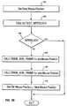
- Fig. 5A illustrates the initialization steps taken when an object is first picked in anticipation of dragging the object by the user and is preferably called when a mouse button is pressed. In
step 500, the mouse focus is locked to maintain a pick on the object pointed to, the current position of the mouse is obtained to compute the position of the object outline as the object is dragged, the drawing mode is set to XOR (which will cause the object to be erased the second it is drawn in the same location) and the color is also set for showing a colored outline of the object as it is dragged. Instep 510, a routine DRAW_XOR_FRAME is called to draw the XOR frame of the object prior to the object being dragged. The DRAW_XOR_FRAME routine is described in greater detail below. Pseudocode for Fig. 5A is provided in TABLE 1.
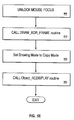
- Fig. 5B illustrates the steps taken when the user starts to drag the object by moving the mouse while the mouse button is pressed. In a
first step 520, the new position of the mouse is obtained. In asecond step 530, routine DETECT_INTERSECT is called to determine whether the movement of the object has caused it to intersect or interlock with another object. This condition is tested instep 540. If an interlock condition has occurred, then the user may not drag the object any further and the drag routine is exited. In an alternative embodiment, the interlocked object may be grouped with the dragged object such that both objects are dragged together. If an interlock condition has not occurred, then processing continues to step 550. Insteps step 570, the old mouse position is set equal to the new mouse position. Pseudocode for Fig. 5B is provided in TABLE 2.
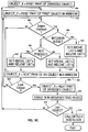
- Fig. 5C illustrates the steps taken to determine whether the dragged object or a part of the dragged object has intersected a new object or part of an object. In a
first step 600, OBJECT_X is set to the first part of the dragged object (for the cases where the dragged object is a concave object split into multiple convex objects). Instep 610, OBJECT_Y is set to the first part of the first object in the window. Instep 620, it is determined whether the two objects intersect for the first time. This can be determined by determining whether any of the edges of the objects intersect and then checking the ABOVE_LIST and BELOW_LIST of each object to see if a prior intersection has occurred. Ifstep 620 is false, then processing continues to step 650 described below. Ifstep 620 is true, then instep 630 it is determined whether the edges of intersection are an interior edge of either OBJECT_X or OBJECT_Y. If yes, then instep 635 the ABOVE_LIST and BELOW_LIST of each object is set to correspond to the ABOVE_LIST or BELOW_LIST of a corresponding part sharing the interior edge. That is, if OBJECT_X is intersecting OBJECT_Y for the first time at an interior edge of OBJECT_Y, then OBJECT_X must have previously intersected the another part that shares the interior edge with OBJECT_Y. IF OBJECT_X is listed as below the other part that shares the interior edge, then OBJECT_X should also be below OBJECT_Y. Oncestep 635 is completed, processing continues to step 650 described below. Ifstep 630 is false, then instep 640 it is determined whether the user is pressing the ALT key to indicate that OBJECT_X (the dragged object) should pass under OBJECT_Y. Of course, alternative embodiments could use other methods to indicate whether the dragged object should pass under or over other objects. Ifstep 640 is false, then instep 645, OBJECT_X is listed in the ABOVE_LIST of OBJECT_Y and OBJECT_Y is listed in the BELOW_LIST of OBJECT_X. Ifstep 640 is true, then instep 647, OBJECT_X is listed in the BELOW_LIST of OBJECT_Y and OBJECT_Y is listed in the ABOVE_LIST of OBJECT_X. In either case, processing continues to step 650.Instep 650, OBJECT_Y is set to the next part of an object in the window. Instep 655, it is determined whether the last part of an object in the window has been processed. If not, then processing returns to step 620. If so, then instep 660, OBJECT_X is set to the next part of the dragged object. Instep 665, all the entries of the previous OBJECT_X ABOVE_LIST and BELOW_LIST are checked to see the all the other parts listed still intersect. This could be easily checked by flagging every entry in the lists during the above described steps 620-650. If non-intersecting entries exists, then those entries should be erased in all lists according to the preferred embodiment. This will allow the user to initially specify that a dragged object is over a second object, withdraw the dragged object from intersecting the second object so that the entries in the lists of both objects are erased, then allowing the user to drag the dragged object under the second object. Instep 670, it is determined whether all the parts of OBJECT_X have been processed. If not, then processing returns to step 610. If so, the routine DETECT_INTERLOCK is called. The routine DETECT_INTERLOCK routine is described in detail below. Pseudocode for Fig. 5C is provided in TABLE 3.
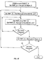
- Fig. 5D illustrates the steps taken to determine whether an interlock condition exists. In a
first step 700, an INTERLOCK_FLAG is set to false, OBJECT_X is set as the dragged object, and OBJECT_Y is set as the first object in the window. Instep 705, VERTEX_V is set as the first vertex of OBJECT_Y. Instep 710, it is determined whether OBJECT_X has encountered VERTEX_V of OBJECT_Y for the first time or whether OBJECT_Y has encountered VERTEX_V of OBJECT_X for the first time (all vertices of both OBJECT_Y and OBJECT_X are checked as VERTEX_V). If not, then processing continues to step 730 described below. Ifstep 710 is true, then instep 715 it is determined whether VERTEX_V is in a concave portion of it's object (OBJECT_Y or OBJECT_X) and whether an interlock condition occurs. An interlock condition occurs given VERTEX_V is a vertex of OBJECT_Y when OBJECT_X is above one part of OBJECT_Y and OBJECT_X is also below a second part of OBJECT_Y and both parts of OBJECT_Y contain VERTEX_V. An interlock condition occurs given VERTEX_V is a vertex of OBJECT_X when OBJECT_Y is above one part of OBJECT_X and OBJECT_Y is also below a second part of OBJECT_X and both parts of OBJECT_X contain VERTEX_V. Ifstep 715 is false, then an interlock condition has not occurred and processing continues to step 730 described below. Ifstep 715 is true, then an interlock condition has occurred and processing continues to step 720. Instep 720, the INTERLOCK_FLAG is set to TRUE and processing continues to step 730. Instep 730, VERTEX_V is set to the next vertex of OBJECT_Y or OBJECT_X (once all the vertices of OBJECT_Y have been processed). Instep 735, it is determined whether all the vertices of OBJECT_Y and OBJECT_X have been processed. If not, then processing returns to step 710. If so, then instep 740, OBJECT_Y is set to the next object in the window. Instep 745, it is determined whether all the objects in the window have been processed. If not, then processing returns to step 705. If so, then processing stops for this routine. Pseudocode for Fig. 5D is provided in TABLE 4.

- Fig. 5E illustrates the termination steps taken when the user completes dragging the graphical object and is called when the mouse button is released. In
step 800, the mouse focus is unlocked thereby releasing the pick of the object. Instep 810, the routine DRAW_XOR_FRAME is called to erase the last XOR frame of the object at the current mouse position. Instep 620, the drawing mode is set back to copy mode from XOR mode. Instep 630, routine OBJECT_REDISPLAY is called to redraw the object in full form at the final mouse position. The OBJECT_REDISPLAY routine is described in greater detail below in reference to 5G. Pseudocode for Fig. 5E is provided in TABLE 5.
Fig. 5F illustrates the steps taken to draw the dragged object and is called by the routines described above. Instep 850, PART_A is set to the first part of OBJECT_X (this is to handle the case where OBJECT_X is concave and has been split into several convex parts or OBJECT_X is a collection of graphical objects). Instep 860, OBJECT_Y is set to the first object of the ABOVE_LIST. Instep 870, PART_A is clipped by OBJECT_Y and OBJECT_Y is set to the next part of the ABOVE_LIST. Instep 875, it is determined whether all the parts of the top list have been processed. If not, then processing returns to step 870, else processing continues to step 880. Instep 880, PART_A is set to the next part of OBJECT_X. Instep 885, it is determined whether all the parts of OBJECT_X have been processed. If not, then processing returns to step 860, else processing stops. Pseudocode for Fig. 5F is provided in TABLE 6.
- Fig. 5G illustrates the steps taken to redisplay a dragged object in a window and is called by the routines described above. In
step 900, the dragged object is drawn and PART_A is set as the first part of the dragged object. Instep 910, the first entry of the ABOVE_LIST of PART_A is retrieved. Instep 920, the object that contains the selected part listed in the ABOVE_LIST of PART_A is displayed. In addition, the next entry of the ABOVE_LIST of PART_A is retrieved. Instep 925, it is determined whether all the entries in the ABOVE_LIST of PART_A have been processed. If not, then processing returns to step 920. If so, then instep 930, PART_A is set to the next part of the dragged object. Instep 935, it is determined whether all parts of the dragged have been processed. If not, then processing returns to step 910. If so, then processing ends. Pseudocode for Fig. 5G is provided in TABLE 7.
Claims (10)
- Apparatus for moving graphical objects, the apparatus comprising:
a display for displaying a plurality of graphical objects according to a display priority;
means for moving, responsive to a user input, a displayed graphical object; and
means for modifying, responsive to a user input, a display priority of the moved graphical object as the graphical object is moved so that the moved graphical object is displayed under a portion of a second displayed graphical object. - Apparatus as claimed in Claim 1 wherein said means for modifying comprises means for modifying the display priority of the moved graphical object as the graphical object is moved so that the moved graphical object is displayed above a second portion of the second displayed graphical object.
- Apparatus as claimed in Claim 2 comprising means for of computing whether the moved graphical object interlocks the second displayed graphical object.
- Apparatus as claimed in Claim 3 comprising means for preventing said moved graphical object from being moved any further if the moved graphical object is computed to interlock the second displayed graphical object.
- Apparatus as claimed in Claim 3 comprising means for of grouping said second displayed graphical object with said moved graphical object so that both objects are moved together.
- A method for moving graphical objects comprising:
displaying a plurality of graphical objects according to a display priority on a display;
moving, responsive to a user input, a displayed graphical object; and
modifying, responsive to a user input, a display priority of the moved graphical object as the graphical object is moved so that the moved graphical object is displayed under a portion of a second displayed graphical object. - A method as claimed in Claim 6 wherein said step of modifying comprises modifying the display priority of the moved graphical object as the graphical object is moved so that the moved graphical object is displayed above a second portion of the second displayed graphical object.
- A method as claimed in Claim 7 comprising the step of computing whether the moved graphical object interlocks the second displayed graphical object.
- A method as claimed in Claim 8 comprising the step of preventing said moved graphical object from being moved if the moved graphical object is computed to interlock the second displayed graphical object.
- A method as claimed in Claim 9 comprising the step of grouping said second displayed graphical object with said moved graphical object so that both objects are moved together.
Applications Claiming Priority (2)
| Application Number | Priority Date | Filing Date | Title |
|---|---|---|---|
| US167754 | 1993-12-15 | ||
| US08/167,754 US5546524A (en) | 1993-12-15 | 1993-12-15 | Method and apparatus for interlocking graphical objects |
Publications (3)
| Publication Number | Publication Date |
|---|---|
| EP0658859A2 true EP0658859A2 (en) | 1995-06-21 |
| EP0658859A3 EP0658859A3 (en) | 1996-02-14 |
| EP0658859B1 EP0658859B1 (en) | 2001-12-12 |
Family
ID=22608685
Family Applications (1)
| Application Number | Title | Priority Date | Filing Date |
|---|---|---|---|
| EP94307336A Expired - Lifetime EP0658859B1 (en) | 1993-12-15 | 1994-10-06 | Method and apparatus for interlocking graphical objects |
Country Status (5)
| Country | Link |
|---|---|
| US (1) | US5546524A (en) |
| EP (1) | EP0658859B1 (en) |
| JP (1) | JP2750318B2 (en) |
| KR (1) | KR0150832B1 (en) |
| DE (1) | DE69429417T2 (en) |
Cited By (1)
| Publication number | Priority date | Publication date | Assignee | Title |
|---|---|---|---|---|
| US6487588B1 (en) | 1996-09-23 | 2002-11-26 | International Business Machines Corporation | Web browser which automatically loads selected types of graphics |
Families Citing this family (17)
| Publication number | Priority date | Publication date | Assignee | Title |
|---|---|---|---|---|
| JP2692782B2 (en) | 1993-12-13 | 1997-12-17 | インターナショナル・ビジネス・マシーンズ・コーポレイション | How to link objects |
| US7289244B2 (en) | 2000-02-02 | 2007-10-30 | Raja Singh Tuli | Portable high speed internet access device |
| US7023572B2 (en) * | 2000-02-02 | 2006-04-04 | Raja Singh Tuli | Portable high speed internet access device |
| US20020030843A1 (en) * | 2000-02-02 | 2002-03-14 | Tuli Raja Singh | Portable high speed internet access device |
| US7356570B1 (en) | 2000-08-29 | 2008-04-08 | Raja Tuli | Portable high speed communication device |
| US7068381B1 (en) | 2000-02-02 | 2006-06-27 | Raja Tuli | Portable high speed internet access device |
| US6633314B1 (en) * | 2000-02-02 | 2003-10-14 | Raja Tuli | Portable high speed internet device integrating cellular telephone and palm top computer |
| US20020115477A1 (en) * | 2001-02-13 | 2002-08-22 | Raja Singh | Portable high speed internet access device with scrolling |
| US6941382B1 (en) | 2000-02-07 | 2005-09-06 | Raja Tuli | Portable high speed internet or desktop device |
| US6874009B1 (en) * | 2000-02-16 | 2005-03-29 | Raja Tuli | Portable high speed internet device with user fees |
| JP3543942B2 (en) * | 2000-03-02 | 2004-07-21 | 株式会社ソニー・コンピュータエンタテインメント | Image generation device |
| US7191211B2 (en) * | 2000-10-03 | 2007-03-13 | Raja Tuli | Portable high speed internet access device priority protocol |
| US6842777B1 (en) | 2000-10-03 | 2005-01-11 | Raja Singh Tuli | Methods and apparatuses for simultaneous access by multiple remote devices |
| US6915327B1 (en) | 2000-10-30 | 2005-07-05 | Raja Singh Tuli | Portable high speed communication device peripheral connectivity |
| US6928461B2 (en) | 2001-01-24 | 2005-08-09 | Raja Singh Tuli | Portable high speed internet access device with encryption |
| US8176428B2 (en) | 2002-12-03 | 2012-05-08 | Datawind Net Access Corporation | Portable internet access device back page cache |
| US8675951B2 (en) * | 2007-05-11 | 2014-03-18 | Three Pixels Wide Pty Ltd. | Method and system for generating a 3D model |
Family Cites Families (9)
| Publication number | Priority date | Publication date | Assignee | Title |
|---|---|---|---|---|
| GB8411579D0 (en) * | 1984-05-05 | 1984-06-13 | Ibm | Graphic display systems |
| US4769636A (en) * | 1985-08-14 | 1988-09-06 | Hitachi, Ltd. | Display control method for multi-window system |
| JP2585515B2 (en) * | 1985-08-16 | 1997-02-26 | 株式会社日立製作所 | Drawing method |
| US5072412A (en) * | 1987-03-25 | 1991-12-10 | Xerox Corporation | User interface with multiple workspaces for sharing display system objects |
| US4888583A (en) * | 1988-03-14 | 1989-12-19 | Ligocki Terry J | Method and apparatus for rendering an image from data arranged in a constructive solid geometry format |
| DE68928531T2 (en) * | 1988-05-27 | 1998-04-16 | Kodak Ltd | DOCUMENT FOLDER IMAGE FOR DISPLAY IN A DATA PROCESSING SYSTEM |
| US5355447A (en) * | 1988-05-27 | 1994-10-11 | Wang Laboratories, Inc. | Method for color image reduction based upon determination of color components of pixels in neighboring blocks |
| US5371845A (en) * | 1990-04-27 | 1994-12-06 | Ashlar, Inc. | Technique for providing improved user feedback in an interactive drawing system |
| US5377317A (en) * | 1991-12-20 | 1994-12-27 | International Business Machines Corporation | Method and apparatus for distinctively displaying windows on a computer display screen |
-
1993
- 1993-12-15 US US08/167,754 patent/US5546524A/en not_active Expired - Lifetime
-
1994
- 1994-10-06 DE DE69429417T patent/DE69429417T2/en not_active Expired - Lifetime
- 1994-10-06 EP EP94307336A patent/EP0658859B1/en not_active Expired - Lifetime
- 1994-11-22 JP JP6288245A patent/JP2750318B2/en not_active Expired - Lifetime
- 1994-12-13 KR KR1019940034539A patent/KR0150832B1/en not_active IP Right Cessation
Non-Patent Citations (2)
| Title |
|---|
| COMPUTER VISION, GRAPHICS, AND IMAGE PROCESSING, OCT. 1986, USA, vol. 36, no. 1, ISSN 0734-189X, pages 42-52, NURMI O 'On translating a set of objects in 2- and 3-dimensional space' * |
| SIGGRAPH '86 CONFERENCE PROCEEDINGS, DALLAS, TX, USA, 18-22 AUG. 1986, vol. 20, no. 4, ISSN 0097-8930, COMPUTER GRAPHICS, AUG. 1986, USA, pages 233-240, BIER E A ET AL 'Snap-dragging (graphics)' * |
Cited By (1)
| Publication number | Priority date | Publication date | Assignee | Title |
|---|---|---|---|---|
| US6487588B1 (en) | 1996-09-23 | 2002-11-26 | International Business Machines Corporation | Web browser which automatically loads selected types of graphics |
Also Published As
| Publication number | Publication date |
|---|---|
| KR0150832B1 (en) | 1998-10-15 |
| JPH07200218A (en) | 1995-08-04 |
| EP0658859B1 (en) | 2001-12-12 |
| DE69429417D1 (en) | 2002-01-24 |
| DE69429417T2 (en) | 2002-08-22 |
| JP2750318B2 (en) | 1998-05-13 |
| US5546524A (en) | 1996-08-13 |
| EP0658859A3 (en) | 1996-02-14 |
| KR950020280A (en) | 1995-07-24 |
Similar Documents
| Publication | Publication Date | Title |
|---|---|---|
| EP0658859B1 (en) | Method and apparatus for interlocking graphical objects | |
| US5734806A (en) | Method and apparatus for determining graphical object visibility | |
| JP3030206B2 (en) | Method and apparatus for clipping a graphic polygon to a clipping area | |
| RU2377663C2 (en) | Dynamic window architecture | |
| KR960016886B1 (en) | Apparatus and method for relating point of selection to object in graphics display system | |
| US5363483A (en) | Updating objects displayed in a computer system | |
| EP0698265B1 (en) | Display compositing system | |
| US6229542B1 (en) | Method and apparatus for managing windows in three dimensions in a two dimensional windowing system | |
| US5678015A (en) | Four-dimensional graphical user interface | |
| US20040075654A1 (en) | 3-D digital image processor and method for visibility processing for use in the same | |
| Bederson et al. | Implementing a zooming user interface: experience building pad++ | |
| EP0693737A2 (en) | Method and apparatus for managing multiprocessor graphical workload distribution | |
| JPH02230470A (en) | Computer graphics display system | |
| KR20060105422A (en) | Compositing desktop window manager | |
| US5926182A (en) | Efficient rendering utilizing user defined shields and windows | |
| US5448688A (en) | Image position interpretation in a graphics system | |
| US5522020A (en) | System and method for rapidly determining relative rectangle position | |
| GB2226219A (en) | Method for three-dimensional clip checking for computer graphics | |
| US8665293B2 (en) | Automatic draw order | |
| US6392662B1 (en) | Draw order preservation in a computer-implemented graphics system | |
| EP1242972B1 (en) | A method and apparatus for ensuring backward compatibility in a bucket rendering system | |
| Slater et al. | Liberation from rectangles: a tiling method for dynamic modification of objects on raster displays | |
| GB2238215A (en) | Computer display system with a three dimensional cursor shadow | |
| JP2667949B2 (en) | Pick event processing method and processing apparatus | |
| CA2068016A1 (en) | Method and apparatus for processing concurrent pick events |
Legal Events
| Date | Code | Title | Description |
|---|---|---|---|
| PUAI | Public reference made under article 153(3) epc to a published international application that has entered the european phase |
Free format text: ORIGINAL CODE: 0009012 |
|
| AK | Designated contracting states |
Kind code of ref document: A2 Designated state(s): DE FR GB |
|
| 17P | Request for examination filed |
Effective date: 19951024 |
|
| PUAL | Search report despatched |
Free format text: ORIGINAL CODE: 0009013 |
|
| AK | Designated contracting states |
Kind code of ref document: A3 Designated state(s): DE FR GB |
|
| RHK1 | Main classification (correction) |
Ipc: G06F 3/033 |
|
| 17Q | First examination report despatched |
Effective date: 19980508 |
|
| GRAG | Despatch of communication of intention to grant |
Free format text: ORIGINAL CODE: EPIDOS AGRA |
|
| GRAG | Despatch of communication of intention to grant |
Free format text: ORIGINAL CODE: EPIDOS AGRA |
|
| GRAH | Despatch of communication of intention to grant a patent |
Free format text: ORIGINAL CODE: EPIDOS IGRA |
|
| GRAH | Despatch of communication of intention to grant a patent |
Free format text: ORIGINAL CODE: EPIDOS IGRA |
|
| GRAA | (expected) grant |
Free format text: ORIGINAL CODE: 0009210 |
|
| AK | Designated contracting states |
Kind code of ref document: B1 Designated state(s): DE FR GB |
|
| PG25 | Lapsed in a contracting state [announced via postgrant information from national office to epo] |
Ref country code: FR Free format text: LAPSE BECAUSE OF FAILURE TO SUBMIT A TRANSLATION OF THE DESCRIPTION OR TO PAY THE FEE WITHIN THE PRESCRIBED TIME-LIMIT Effective date: 20011212 |
|
| REG | Reference to a national code |
Ref country code: GB Ref legal event code: IF02 |
|
| REF | Corresponds to: |
Ref document number: 69429417 Country of ref document: DE Date of ref document: 20020124 |
|
| EN | Fr: translation not filed | ||
| PLBE | No opposition filed within time limit |
Free format text: ORIGINAL CODE: 0009261 |
|
| STAA | Information on the status of an ep patent application or granted ep patent |
Free format text: STATUS: NO OPPOSITION FILED WITHIN TIME LIMIT |
|
| 26N | No opposition filed | ||
| REG | Reference to a national code |
Ref country code: GB Ref legal event code: 746 Effective date: 20080925 |
|
| PGFP | Annual fee paid to national office [announced via postgrant information from national office to epo] |
Ref country code: GB Payment date: 20131021 Year of fee payment: 20 Ref country code: DE Payment date: 20131023 Year of fee payment: 20 |
|
| REG | Reference to a national code |
Ref country code: DE Ref legal event code: R071 Ref document number: 69429417 Country of ref document: DE |
|
| REG | Reference to a national code |
Ref country code: GB Ref legal event code: PE20 Expiry date: 20141005 |
|
| PG25 | Lapsed in a contracting state [announced via postgrant information from national office to epo] |
Ref country code: GB Free format text: LAPSE BECAUSE OF EXPIRATION OF PROTECTION Effective date: 20141005 |