EP0659561A2 - Thermal ink-jet head - Google Patents
Thermal ink-jet head Download PDFInfo
- Publication number
- EP0659561A2 EP0659561A2 EP94120551A EP94120551A EP0659561A2 EP 0659561 A2 EP0659561 A2 EP 0659561A2 EP 94120551 A EP94120551 A EP 94120551A EP 94120551 A EP94120551 A EP 94120551A EP 0659561 A2 EP0659561 A2 EP 0659561A2
- Authority
- EP
- European Patent Office
- Prior art keywords
- ink
- channel
- nozzle
- flow channel
- reservoir
- Prior art date
- Legal status (The legal status is an assumption and is not a legal conclusion. Google has not performed a legal analysis and makes no representation as to the accuracy of the status listed.)
- Granted
Links
Images


Classifications
-
- B—PERFORMING OPERATIONS; TRANSPORTING
- B41—PRINTING; LINING MACHINES; TYPEWRITERS; STAMPS
- B41J—TYPEWRITERS; SELECTIVE PRINTING MECHANISMS, i.e. MECHANISMS PRINTING OTHERWISE THAN FROM A FORME; CORRECTION OF TYPOGRAPHICAL ERRORS
- B41J2/00—Typewriters or selective printing mechanisms characterised by the printing or marking process for which they are designed
- B41J2/005—Typewriters or selective printing mechanisms characterised by the printing or marking process for which they are designed characterised by bringing liquid or particles selectively into contact with a printing material
- B41J2/01—Ink jet
- B41J2/135—Nozzles
- B41J2/14—Structure thereof only for on-demand ink jet heads
- B41J2/14016—Structure of bubble jet print heads
- B41J2/14032—Structure of the pressure chamber
- B41J2/1404—Geometrical characteristics
-
- B—PERFORMING OPERATIONS; TRANSPORTING
- B41—PRINTING; LINING MACHINES; TYPEWRITERS; STAMPS
- B41J—TYPEWRITERS; SELECTIVE PRINTING MECHANISMS, i.e. MECHANISMS PRINTING OTHERWISE THAN FROM A FORME; CORRECTION OF TYPOGRAPHICAL ERRORS
- B41J2/00—Typewriters or selective printing mechanisms characterised by the printing or marking process for which they are designed
- B41J2/005—Typewriters or selective printing mechanisms characterised by the printing or marking process for which they are designed characterised by bringing liquid or particles selectively into contact with a printing material
- B41J2/01—Ink jet
- B41J2/135—Nozzles
- B41J2/14—Structure thereof only for on-demand ink jet heads
- B41J2002/14379—Edge shooter
-
- B—PERFORMING OPERATIONS; TRANSPORTING
- B41—PRINTING; LINING MACHINES; TYPEWRITERS; STAMPS
- B41J—TYPEWRITERS; SELECTIVE PRINTING MECHANISMS, i.e. MECHANISMS PRINTING OTHERWISE THAN FROM A FORME; CORRECTION OF TYPOGRAPHICAL ERRORS
- B41J2202/00—Embodiments of or processes related to ink-jet or thermal heads
- B41J2202/01—Embodiments of or processes related to ink-jet heads
- B41J2202/03—Specific materials used
Abstract
Description
- The present invention relates to a thermal ink-jet head which produces air bubbles in ink by using of heat generated by a resistive element for producing bubbles and jets the ink from nozzles by means of the air bubbles thus produced so as to execute recordings, and more specifically, relates to an ink flow channel structure in the thermal ink-jet head.
- For example, Unexamined Japanese Patent Publication No. Sho. 61-230954 discloses the flow channel structure of a known thermal ink-jet head which includes a first Si-substrate (heater substrate) and a second Si-substrate (channel substrate) in which a heating element is formed in the first Si-substrate, whereas nozzles and an ink reservoir are formed in the second Si-substrate by using ODE (anisotropic etching).
- In the case of a thermal ink-jet head as disclosed in Unexamined Japanese Patent Publication No. Hei. 1-148560, the method of forming nozzles includes the steps of preparing a nozzle unit and an ink reservoir in the form of independent grooves to ensure that the length of each nozzle is made controllable, and coupling them via a recess (a bypass) provided in the polyamide layer of the first Si-substrate. The ink flow channel of the thermal ink-jet head thus formed tends to allow the impurities contained in ink to gather in the bypass because the bypass is narrow and curved. The problem in this case is that the nozzles are easily prevented from being supplied with ink. The foreign substances gathered in the bypass impair the supply of ink to the nozzles and deteriorates the repeat jet characteristics of the nozzles, thus making a jet drop smaller or otherwise rendering ink jet completely impossible. These malfunctions results in lowering image quality. On the other hand, it is extremely difficult to prevent such foreign substances from mixing with ink or slipping into the head during the process of manufacture; in other words, some foreign substances are unavoidably mixed therewith.
- In order to prevent image quality from deteriorating because of foreign substance, for example, Unexamined Japanese Patent Publication No. Hei. 5-124206 has proposed to narrow an entry port of each individual ink flow channel so as to trap such foreign substances and provide a common ink flow channel to supply ink flow channel instead of relying on the ink flow channels clogged with foreign substances. Further, Unexamined Japanese Patent Publication No. Hei. 4-351842 has proposed to provide a common slit in a polyamide layer so as to supply ink from the common slit when foreign substances gather in a bypass.
- Moreover, in order to surely trap foreign substances, for example, Japanese Patent Application No. Hei. 5-246419 discloses an arrangement which includes the steps of disposing a plurality of ink flow channels between the ink reservoir of a channel substrate and individual nozzle channels, and using not only a common slit provided in a polyamide layer to couple the individual nozzle channels with the ink flow channel but also a bypass provided in the polyamide layer likewise to couple the ink flow channel and the ink reservoir together. A thermal ink-jet head of this type ensures that foreign substances are trapped at the entry port of the nozzle channel together with the bypass. Even if foreign substances gather in this entry port, no deterioration in jet characteristics occurs since ink is supplied from the common slit.
- However, in this type, since the whole length of the channel is lengthened because of having the ink flow channel, the resistance of the flow channel is increased, thereby lowering the filling efficiency. In other words, the frequency is ultimately lowered when printing is carried out. Similarly, it results in making the head costly that the flow channel is lengthened. Consequently, the longer the flow channel, the greater the length of the Si-device necessary for forming the nozzles becomes and this also results in decreasing the number of Si-devices available from one sheet of Si wafer. An increase in the length of such a flow channel would cause the production cost per device on the assumption that the yield rate remains invariable.
- Subsequently, Japanese Patent Application No. Hei. 5-269899 has proposed an arrangement in which a polyamide wall is dispensed so that an recess in a bubble generating resistive element is coupled to a common slit. With this arrangement, a flow channel can be shortened to the extent of the wall used to separate the recess in the bubble generating resistive element from the common slit and besides ink can smoothly be transferred onto the bubble generating resistive element. While the ability of trapping foreign substances in a bypass and the entry port of a nozzle channel is maintained, the flow channel resistance is thus reduced, whereby high-speed, stable ink-jetting can be performed.
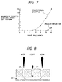
- Notwithstanding, the arrangement disclosed in Japanese Patent Application No. Hei. 5-269899 has presented a new problem in that a nozzle-to-nozzle cross stroke is produced. Fig. 8 illustrates a cross stroke phenomenon in a conventional thermal ink-jet head and Fig.9 is a graphic representation depicting printing frequencies and the number of defective image quality in a solid printing unit. In Fig. 8,
reference numeral 21 denotes nozzle channels; and 22, a common slit. Fig. 8 shows a recess ranging from a bubble generating resistive element to a common slit and nozzle channels formed in a channel substrate on the same plane; there are shown threenozzle channels # nozzle channels # nozzle channels # nozzle channel # 2 at this time, thenozzle channel # 2 is sending small ink drops. As a result, an unintended dot appears on paper, thus deteriorating image quality and this is because the bubble pressure applied to the adjoiningnozzle channels # common slit 22 to thenozzle channel # 2 as shown by arrows in Fig. 8. This phenomenon does not occur when ink jets are sent out of the whole nozzle channel but occurs in the case of an every-other-dot pattern. For this reason, any frequency liable to causing defects in improved in the solid printing unit as shown by solid lines, in comparison with an ordinary head as shown by dotted lines therein. Nevertheless, defective image quality has become conspicuous in the every-other-dot pattern. - With the arrangement above, the bubble pressure generated on the bubble generating resistive element is directly transmitted to the wall surface of the groove in the polyamide layer. Since the common slit is provided along the wall surface of the groove, the bubble pressure is directly propagated to the common slit. The cross stroke is considered as what has been produced accordingly.
- On the other hand, Unexamined Japanese Patent Publication No. Hei. 5-116303, for example, discloses an ink-jet recording head so designed that the bubble pressure generated on a bubble generating resistive element is prevented from being transmitted to the rear of an ink flow channel. In this recording head, a flow channel in the rear of the bubble generating resistive element is narrowed. With this arrangement, since the bubble pressure generated on the bubble generating resistive element is blocked in the narrow portion of the flow channel, the propagation of the pressure in the rear of the bubble generating resistive element is reduced. However, no consideration has been given to the effect of foreign substances in the patent publication above. Since the whole flow channel section is directly regulated by planar throttling in this thermal ink-jet head, moreover, the flow channel resistance will increase if the flow channel is excessively narrowed, thus deteriorating the frequency response characteristic of the ink jet.
- In view of the foregoing problems, it is an object of the present invention to provide a thermal ink-jet head so designed as to improve operating frequency by surely trapping foreign substances and reducing the influence of a cross stroke.
- A thermal ink-jet head of the present invention is comprised of a heater substrate having bubble generating resistive elements; a channel substrate having a plurality of nozzle channels, an ink reservoir, and ink supplying opening, the nozzle channels being formed in the channel substrate to pass on the bubble generating resistive elements and extends up to a position close to an end portions of the bubble generating resistive elements; a coupling flow channel for communicating with each nozzle channel, which is provided between the plurality of nozzle channels and the ink reservoir on the channel substrate; and a synthetic resin layer provided on the heater substrate, the synthetic resin layer having a groove which at least extending from an upper part of the bubble generating element up to a position where the groove is coupled to the flow channel formed in the channel substrate.
- According to the present invention, the nozzle channel formed in the channel substrate is passed on the bubble generating resistive element and extended up to the rear end of the bubble generating resistive element and the flow channel is provided in such a way as to communicate with each nozzle channel between the plurality of nozzle channels of the channel substrate and the ink reservoir, and further the recess provided in the synthetic resin layer is extended from the upper part of the bubble generating resistive element up to the position where it is coupled to the flow channel with the effect of decreasing the whole length of the nozzle. Moreover, foreign substances are trapped at the entry port of the nozzle channel and defective image quality can be reduced by supplying ink in a roundabout way to any portion where the flow of ink is obstructed because of foreign substances with which the flow channel is clogged. Further, the channel substrate is provided with the flow channel and the ink flow channel is curved toward the groove in the synthetic resin layer from the flow channel and further curved to reach the upper part of the bubble generating resistive element, so that the bubble pressure generated in the bubble generating resistive element is prevented from directly propagating through the adjoining nozzle channels via the flow channel. The cross stroke can thus be reduced.
- In the accompanying drawings,
- Fig. 1 is a schematic perspective view of a thermal ink-jet head of a first embodiment of the present invention;
- Fig. 2A is a sectional view of a flow channel in the thermal ink-jet head of the first embodiment;
- Fig. 2B is a three-side diagram of a flow channel in the thermal ink-jet head of the first embodiment;
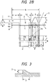
- Fig. 3 is a partial enlarged view of a pit in the thermal ink-jet head of the second embodiment;
- Fig. 4 is an enlarged perspective view of the vicinity of a pit in the thermal ink-jet head of the first embodiment;
- Figs. 5A and 5B are partial enlarged views of an example of a design pattern of a polyamide mask;
- Figs. 6A and 6B are illustrations of examples of forming bubbles;
- Fig. 7 is a graphic representation showing frequency response characteristics in the thermal ink-jet head of the first embodiment;
- Fig. 8 is an illustration of a cross stroke in a conventional thermal ink-jet head;
- Fig. 9 is a graphic representation showing printing frequency and the number of image quality defects in solid printing;
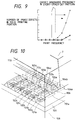
- Fig. 10 is a schematic perspective view of a flow channel's structure of a thermal ink-jet head of a second embodiment of the present invention;
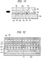
- Fig. 11 is a sectional view showing the flow channel at the center of a nozzle in the thermal ink-jet head of the second embodiment;
- Fig. 12 is a plan view showing a structure of the flow channel in the thermal ink-jet head of the second embodiment;
- Figs. 13A and 13B are partial enlarged views of the vicinity of a bypass pit in the thermal ink-jet head of the second embodiment;
- Fig. 14 is a partial enlarged view of the vicinity of a sub-reservoir in the thermal ink-jet head of the second embodiment;
- Fig. 15 is a graph showing the number of printing defects when foreign substances are allowed to be mixed with ink;
- Fig. 16 is a schematic perspective view of a flow channel's structure of a thermal ink-jet head of a third embodiment of the present invention;
- Fig. 17 is a sectional view showing the flow channel at the center of a nozzle in the thermal ink-jet head of the third embodiment; and
- Fig. 18 is a plan view showing a structure of the flow channel in the thermal ink-jet head of the second embodiment.
- The preferred embodiments of the present invention will be described referring to the accompanying drawings as follows.
- Fig. 1 is a schematic perspective view of a thermal ink-jet head of a first embodiment of the present invention. Fig. 2B is a diagram illustrating three sides of the flow channel structure. Fig. 3 is a partial enlarged view of a pit. Fig. 4 is an enlarged perspective view of a portion near a pit. In these drawings,
reference numerals - The thermal ink-jet head included the
channel wafer 11 and theheater wafer 8 on which thepolyamide layer 9 is formed, these wafers being bonded together. Theheater wafer 8 is made of Si, for example, and contains a plurality ofheating elements protective layer 10 for protecting the electrodes is formed on theheater wafer 8 and, further, thepolyamide layer 9 is formed thereon.Pits coupling flow channel 6 from the upper parts of theheating elements bypass pit 4 for coupling theink reservoir 7 with thecoupling flow channel 6 are formed in thepolyamide layer 9 by etching or the like. On the other hand, thechannel wafer 11 is also made of Si, and thenozzle channels coupling flow channel 6 and theink reservoir 7 are formed thereon by ODE, for example. - The
pit 2 slightly eats away thepolyamide layer 9 in front of theheating element 1 as shown in Fig. 2B. Moreover, thepit 2 is configured so that it throttles the flow channel in terms of a plane in the rear portion of theheating element 1. Such a configuration can easily be attained by designing a mask pattern on thepolyamide layer 9 in conformity with the configuration of thepit 2. A position where the pit is placed is gradually narrowed toward theheating element 1 from the smallest blockage of the flow channel due to thechannel pressure wall 12 and minimized in terms of a plane right behind theheating element 1. - Further, the
polyamide wall 3 formed at the joint between thepit 2 and thecoupling flow channel 6 have a semicircular shape. Since the end of the extension of thepit 2 apparently functions as a pressure reflective wall against the bubble pressure generated in theheating element 1, a reduction in the cross stroke can be achieved by rendering the end portion thereof to have a pressure-wave absorbing structure. In order to actually design the circular structure, a polygonal structure is to be employed for a polyamide mask pattern. Figs. 5A and 5B illustrate partial enlarged design patterns of such a polyamide mask by way of example. As shown in Fig. 5A, the simplest mask pattern is triangular, which is followed by what is pentagonal as shown in Fig. 5B. Therefore, the mask pattern does not have to be completely semicircular and in this embodiment, an octadecagon has been employed. The actually resultingpolyamide wall 3 becomes substantially semicircular due to the restriction of resolution. - On the other hand, a non-etching portion between the
nozzle channel 5 and thecoupling flow channel 6 is placed at the rear end of the throttled portion of thepit 2. Consequently, the tiltedchannel pressure wall 12 is formed at the end of thenozzle channel 5 formed by ODE. As shown in Fig. 4, thechannel pressure wall 12 is such that the flow channel can be expanded three-dimensionally in the throttled portion of thepit 2, thus increasing the total cross sectional area of the flow channel increases. Since thechannel pressure wall 12 is substantially extended up to the end of theheating element 1, it functions as what controls the growth of the bubble produced on theheating element 1 and reflects the bubble pressure in the direction of an ink outlet. - The
coupling flow channel 6 of thechannel substrate 11 is extended in the nozzle orientating direction so as to couple a plurality of nozzles together. If one of theindividual bypass pits 4 is clogged with foreign substances or fails to make ink flow smoothly therein, it is possible to supply ink from an adjoiningbypass pit 4 via thecoupling flow channel 6. Thecoupling flow channel 6 may be set common to the whole nozzle or otherwise provided for any one of the groups of nozzles. In the latter case, though the adjoining block-to-block cross stroke may be prevented, the supply of ink to the peripheral nozzles may be lower in quantity than what is supplied to those in the central part. - The
coupling flow channel 6 thus functions as an ink pool; by this is meant that it has the effect of improving the supply of ink to the nozzles. Therefore, it is preferred for thecoupling flow channel 6 to have a volume as great as possible. The size of thecoupling flow channel 6 is determined under the restriction of chip size. - Further, the
coupling flow channel 6 has the effect of attenuating the backward propagation of the bubble pressure generated on theheating element 1. In other words, the bubble pressure is caused to collide with the rear end of thepit 2 so that the pressure is turned upward, and further to collide with the sidewall and upper face of thecoupling flow channel 6 so as to be turned its direction again. Consequently, the pressure applied to theink reservoir 7 and the adjoining nozzles is attenuated with the effect of decreasing the cross stroke. - The
bypass pit 4 is individually provided for each nozzle. However, thebypass pit 4 can be formed as a slit-like groove. Further, thebypass pit 4 can be constructed so that an underside of the not-etching portion between theink reservoir 7 and thecoupling flow channel 6 is for common use to make them individual openings. - As shown in Fig. 2A, ink flows from the
ink reservoir 7 via thebypass pit 4 and thecoupling flow channel 6 up to thepit 2 andnozzle channel 5. There is provided a filter in two places where foreign substances can be trapped. Large ones out of the foreign substances that have penetrated into theink reservoir 7 are trapped at the entry port of thebypass pit 4. Although it is very rare for large foreign substances to pass through that portion, they are still trapped at the entry port of thecoupling flow channel 6. As the foreign substances passing through the filter are extremely small in quantity, thenozzle channel 5 is seldom clogged therewith and the foreign substances together with ink are quickly jetted from the nozzle. Even when the foreign substances or bubbles are trapped at the entry port of thebypass pit 4 or thecoupling flow channel 6 to cause thebypass pit 4 to be clogged therewith, ink can be supplied to any nozzle deficient in ink supplementary by supplying ink from an adjoining nozzle or what is in the neighborhood thereof via thecoupling flow channel 6. It is thus possible to compensate for deficiency in the supply of ink to the extent that actual image quality is distinguishable. - The ink made to flow into the
pit 2 is passed through the throttled portion of thepit 2 to be supplied onto theheating element 1. Although the flow channel in plane of this portion is narrow, the total sectional area of the flow channel is increased as it is widened three-dimensionally by thechannel pressure wall 12 to prevent the flow channel resistance from increasing. Consequently, ink is supplied onto theheating element 1 via the throttled portion of thepit 2 and along thechannel pressure wall 12 after the bubble is produced on theheating element 1 to ensure that the ink is smoothly refilled. The frequency response characteristic of the ink is never deteriorated. - When the bubble is produced on the
heating element 1, a good bubble can be formed in accordance with the configuration of thepit 2 around theheating element 1 as noted previously. Figs. 6A and 6B illustrate processes of forming a bubble by way of example. In the case of such a conventional thermal ink-jet head as disclosed in Japanese Patent Application No. Hei. 5-269899, for example, pits 2a, 2b, 2c have been coupled directly to the common slit from aboveheating elements coupling flow channel 6 is reduced. - Referring to Fig. 2B, a detailed description will subsequently be given of a thermal ink-jet head of the present invention, The
nozzle channels polyamide layer 2 is approximately 115 µm and the width b of the channel layer is approximately 54 µm. The length c of the removed portion in front of theheating element 1 of thepit 2 is set at approximately 10 µm, for example. The width of the flow channel of thepit 2 right under thechannel pressure wall 12 is about 54 µm; this is the narrowest portion having the dimensions defined by the width of polyamide opening and the thickness of polyamide, namely, 54 x 25 µm. The configuration of the polyamide wall of thepit 2 is made octadecagonal as mentioned above, which is close to semicircular. - The throttled portion of the
pit 2 is prepared by reducing its one side e right under thechannel pressure wall 12 by about 15 µm, 30 µm in total. In other words, the plane of the flow channel of thepit 2 is reduced to about 44% toward theheating element 1 from right under thechannel pressure wall 12. The length f of the flow channel from the starting point of throttling up to the immediate end of theheating element 1 ranges from the starting point of throttling, that is, a starting position where thechannel pressure wall 12 is formed up to the immediate end of the heating element to the immediate end of the heating element, which is about 30 µm. Further, the width g of thepit 2 in the portion of theheating element 1 is about 60 µm and with respect to the width of thepit 2 on theheating element side 1, the width of the throttled opening is reduced to 40%. The shortest length h of the non-etching portion between thenozzle channel 5 and thecoupling flow channel 6 is about 15 µm, whereas the shortest length i of the non-etching portion between thecoupling flow channel 6 and theink reservoir 7 is set at about 10 µm. - With respect to the
coupling flow channel 6, the bottom side j of a trapezoid in cross section thereof is set about 110 µm. A satisfactory effect can be obtained from the size mentioned above. Moreover, the height k of thecoupling flow channel 6 is determined by the etching time of the channel plate, which is approximately 60 µm. - The sum of the width l of the opening of the
bypass pit 4 which functions as a filter for trapping foreign substances and the thickness m of the adjoining partitions is 84.5 µm equivalent to a nozzle arranging pitch. The length n of the opening on theink reservoir side 7 separated by achannel partition 21, that is, the length of a first filter is 60 µm, and the length o of the opening on the couplingflow channel side 6, that is, the length of a second filter is 44 µm. The shortest space p between thepit 2 and thebypass pit 4, that is, the length of the portion on the central line of the flow channel of Fig. 2B is 20 µm. The whole length Q from the end of the nozzle up to thechannel partition 21 is 410 µm. - Fig. 7 is a graphic representation illustrating frequency response characteristics in the thermal ink-jet head according to the present invention. In Fig. 7, there is shown a relation between printing frequency when an every-other-dot pattern is printed and the number of defects brought about. In the case of the conventional head, image quality has been affected seriously even by a low printing frequency when such an every-other-dot pattern is printed. However, as shown in Fig. 7, no defects are seen to result from a high printing frequency, which has heretofore caused defects very often, and desired image quality is maintained by the thermal ink-jet heed according to the present invention. Therefore, it has become possible to greatly improve problematical defect-causing frequencies in half tone in any other conventional heads. More specifically, operations ranging from 10 to 12 kHz are practically performable without any difficulty. In other words, approximately 20 kHz is possible as printing frequency in a character mode as it does not require a flow rate so much in the case of solid or half tone.
- As set forth above, according to the present invention, the flow channel structure functioning as what is capable of trapping foreign substances and the like prevents the nozzle from being clogged up and even when such foreign substances are trapped, the coupling flow channel is unable for supplying ink. Good image quality can thus be maintained. Moreover, the groove structure in the polyamide layer together with the coupling flow channel makes it possible to generate bubbles with stability and to suppress the propagation of the bubble pressure rearwardly. As the bubble pressure is effectively utilizable, the cross stroke is also reducible. Consequently, good image quality is obtainable even when an every-one-dot pattern in painted and operating frequencies are improved with the effect of making a high-speed printer available. Since the whole length of the flow channel is short, the device is reducible in size and this results in securing more substrates per wafer inexpensively.
- Fig. 10 is a perspective view of a flow channel structure in a second embodiment of a thermal ink-jet head of the present invention. Fig. 11 is a sectional view of a flow channel in the center of a nozzle. Fig. 12 is a top view of the flow channel structure. Fig. 13 is a partial enlarged view of the vicinity of a bypass pit. Fig. 14 is a partial enlarged view of the vicinity of a sub-reservoir.
Reference numerals - The thermal ink-jet head includes a
channel wafer 110 and aheater wafer 108 on which apolyamide layer 109 is formed, these wafers being bonded together. Theheater wafer 108 is made of Si, for example, and contains a plurality ofheating elements polyamide layer 109 is formed on the combination of these wafers.Pits bubble 103 are formed on theheating elements ink flow channels coupling nozzle channels bypass pits ink reservoir 107 and the sub-reservoir 106 are formed on thepolyamide layer 109 by etching, for example. On the other hand, thechannel wafer 110 is also made of Si, and thenozzle channels ink reservoir 107 are formed by ODE, for example. The sub-reservoir 106 is extended in the orientating direction of the nozzles. One sub-reservoir common to the whole nozzle may be provided or otherwise provided for nozzles on a group basis. - Ink is made to flow from the
ink reservoir 107 via thebypass pit 104 to the sub-reservoir 106 as shown in Fig. 11. The portion of thebypass pit 104 is curved and narrow in cross section, and also functions as a filter to ensure thatforeign substances 111 are trapped therein. As a specific example of thebypass pit 104, for example, the length L2 of theink reservoir side 107 is set at 40 µm; the length L1 of thesub-reservoir side 106 at 40 µm; and the length L3 of the projected portion of thechannel substrate 10 at 20 µm. As a minimum sectional portion, the width W is set at 50 µm and the height H1 at 20 µm to form a rectangle. The shape of foreign substances flowing in are mostly fibrous and they collide with and trapped by the polyamide wall on thesub-reservoir side 106 of thebypass pit 104. Other kinds of large foreign substances and air bubbles are trapped by an opening on theink reservoir side 107 and those which are passed through this portion are trapped by the minimum sectional portion under the projected portion of thechannel substrate 110. Even when such foreign substances are trapped by part of thebypass pit 104, the sub-reservoir 106 will never suffer from the shortage of ink since ink is supplied from any other portion to the sub-reservoir 106. - The ink supplied to the sub-reservoir 106 is brought into the
nozzle channel 105 via theink flow channel 112. If large foreign substances or air bubbles are trapped in the ink flow channel, the fluid resistance increases to result in insufficient supply of ink to the nozzle. Inferior ink-jetting such as a reduction in dot size and mis-jetting is thus caused. According to the present invention, however, foreign substances and air bubbles are trapped by thebypass pit 104 and as for an individual nozzle, ink is supplied from the sub-reservoir 106 as a common liquid chamber. Consequently, even though a part of thebypass pit 104 is clogged with foreign substances, the supply of ink remains unaffected thereby. As shown in Fig. 14, the sub-reservoir 106 is a common slit which is trapezoidal in cross section. For example, the length L4 of the base is set at 120 µm and the height L5 at 70 µm to form the sub-reservoir 106. Like the specific example of thebypass pit 4 above, thepolyamide layer 109 is about 20 µm in height, whereas the height of the sub-reservoir 106 may be about 70 µm or greater, whereby a sufficient quantity of ink can be stored therein. Therefore, ink can be supplied to the nozzle channel at low channel resistance in comparison with the communicating channel or the common slit conventionally provided in the polyamide layer. The operating frequency is thus improved. - Fig. 15 is a graph showing the number of printing defects when foreign substances are allowed to be mixed with ink. As a conventional example, used is a conventional head having no sub-reservoir, which supplies ink to the nozzle channel using only an individual bypass pit. As is apparent from Fig. 15, a comparison between the conventional head and what embodies the present invention reveals that the mixture of foreign substances has not brought about almost any defects. Since the ink supplied to the head is passed through a filter provided separately, a large quantity of foreign substances during the experiments is not actually mixed in the ink. In the case of the structure in the second embodiment of the present invention, moreover, even if a ink supplying channel which has been conventionally provided is not used, image quality is not badly affected by foreign substances, thereby improving sufficient resistance to foreign substances. In other words, it is feasible to decrease not only the number of parts but also production costs.
- Fig. 16 is a perspective view of a flow channel structure in a third embodiment of a thermal ink-jet head of the invention. Fig. 17 is a sectional view of a flow channel in the center of a nozzle. Fig. 18 is a top view of the flow channel structure. In these drawings, like reference characters designate like members of Figs. 10 through 14 and the description thereof will be omitted. In the third embodiment of the present invention, the
pit 102 and theink flow channel 112 in the second embodiment thereof are coupled together to form anintegral pit 102. With this arrangement, the whole channel length can be reduced to the extent of the wall of the polyamide layer used to separate theink flow channel 112 from thepit 102 in the second embodiment of the present invention. - If the channel is long, the channel resistance increases and filling efficiency of ink lowers, thus causing the printing frequency to be also lowered. If, moreover, the channel is long, the length of the Si-device for use as a substrate increases. Consequently, the number of substrates obtainable from one Si-wafer is reduced and the cost of one nozzle device rises if the channel is long on the assumption that the yield ratio is the same. According to the third embodiment of the present invention, the channel resistance is lowered as the channel length can be decreased and the operating frequency is made improvable. Moreover, it is possible to offer inexpensive nozzle devices.
- Even in the third embodiment of the present invention, the
bypass pit 104 functions as a filter and when ink flows from theink reservoir 107 viabypass pit 104 to the sub-reservoir 106, foreign substances in the ink are trapped by a part of thebypass pit 104. When the foreign substances are trapped by that part of thebypass pit 104, ink is supplied from the sub-reservoir 106 via thepit 102 onto theheating element 101 and thenozzle channel 105, so that image quality is prevented from deteriorating. Further, ink is supplied onto theheating element 101 simultaneously with the parallel movement of ink. Therefore, the flow channel resistance is lower than a case where ink is supplied via thenozzle channel 105 to thepit 102 as in the second embodiment of the present invention. Thus ink can be refilled at high speed and the operating frequency is also made improvable. - With the arrangement in the third embodiment of the present invention, the end of the
nozzle channel 105 is located on thepit 102 When the whole channel is shortened, the end of thenozzle channel 105 may be located near the end portion of theheating element 101. As thenozzle channel 105 is formed by ODE, its end portion forms a tilted face. By locating the titled face close to the end portion of theheating element 101, the shape of the bubble produced on theheating element 101 is controlled. The bubble pressure is reflected from the tilted face and directed to the opening of the nozzle, so that the bubble pressure is effectively utilizable. - With the arrangement shown in the second and third embodiments of the present invention, the provision of the
bypass pit bypass pit bypass pit bypass pit 104 should be installed in an optimum range in consideration of the conditions stated above.
Claims (12)
- A thermal ink-jet head comprising:
a heater substrate having bubble generating resistive elements;
a channel substrate having a plurality of nozzle channels, an ink reservoir, and ink supplying opening, said nozzle channels being formed in said channel substrate to pass on the bubble generating resistive elements and extends up to a position close to an end portions of said bubble generating resistive elements;
a coupling flow channel for communicating with each nozzle channel, which is provided between said plurality of nozzle channels and said ink reservoir on said channel substrate; and
a synthetic resin layer provided on said heater substrate, said synthetic resin layer having a groove which at least extends from an upper part of said bubble generating element up to a position where said groove is coupled to said flow channel formed in said channel substrate. - A thermal ink-jet head as claimed in claim 1, wherein said groove has a shape in that its sectional area is reduced in the direction of orientating the nozzle channel in the distance from the bubble generating resistive element up to the flow channel and each of said plurality of nozzle channels has a tilted surface which is expanded in a direction of orientating said nozzle channel and in a direction perpendicular to an extending direction of said nozzle channel.
- A thermal ink-jet head as claimed in claim 1, wherein said nozzle channel extends from said bubble generating resistive element up to a position where in communications with said flow channel so as not to form a face perpendicular to a expanding direction of said nozzle channels.
- A thermal ink-jet heed as claimed in claim 1, wherein said groove is enlarged in a direction of said ink-jet port of said flow channel from an upper part of said bubble generating resistive element.
- An ink-jet recording apparatus comprising:
a plurality of ink-bet portions, each ink-jet portion having a nozzle which has a jetting opening and an end portion, a recess being provided in said nozzle, a heat resistive element provided in said recess and an ink reservoir located beneath said end portion to communicate with said recess;
a space for use in coupling each ink reservoir; and
an ink providing means for providing an ink to each ink reservoir. - An ink-jet recording apparatus as claimed in claim 5, wherein said ink reservoir has a nonlinear surface.
- An ink-jet recording apparatus as claimed in claim 5, wherein an end portion in said nozzle has non-perpendicular surface.
- An ink-jet recording apparatus as claimed in claim 1, wherein said ink reservoir has a portion whose width is partially narrowed.
- An ink-jet recording apparatus as claimed in claim 1, wherein said recess has a base larger than that of said heating resistive element and said heating resistive element is located opposite to said ink-jet portion.
- An ink-jet recording apparatus as claimed in claim 5, wherein an end portion in said nozzle is provided in a position corresponding to said ink reservoir.
- An ink-jet recording apparatus comprising:
a heater substrate having bubble generating resistive elements;
a channel substrate having a plurality of nozzle channels, an ink reservoir, and ink supplying opening,
a sub-reservoir provided between said nozzle channels of said channel substrate and said ink reservoir;
a synthetic resin layer provided on, said heater substrate;
first grooves for coupling each of said nozzle channels and said sub-reservoir, which correspond at least to each nozzle channel formed on said channel substrate; and
a plurality of second grooves for coupling said ink reservoir and sub-reservoir. - A ink-jet recording apparatus as claimed in claim 11, wherein said first grooves for coupling each of said nozzle channels and said sub-reservoir couples with a recess provided on said bubble generating resistive elements.
Applications Claiming Priority (6)
| Application Number | Priority Date | Filing Date | Title |
|---|---|---|---|
| JP35310793A JP2812175B2 (en) | 1993-12-27 | 1993-12-27 | Thermal inkjet head |
| JP35310693 | 1993-12-27 | ||
| JP35310793 | 1993-12-27 | ||
| JP35310693 | 1993-12-27 | ||
| JP353106/93 | 1993-12-27 | ||
| JP353107/93 | 1993-12-27 |
Publications (3)
| Publication Number | Publication Date |
|---|---|
| EP0659561A2 true EP0659561A2 (en) | 1995-06-28 |
| EP0659561A3 EP0659561A3 (en) | 1998-06-03 |
| EP0659561B1 EP0659561B1 (en) | 2001-10-31 |
Family
ID=26579764
Family Applications (1)
| Application Number | Title | Priority Date | Filing Date |
|---|---|---|---|
| EP94120551A Expired - Lifetime EP0659561B1 (en) | 1993-12-27 | 1994-12-23 | Thermal ink-jet head |
Country Status (3)
| Country | Link |
|---|---|
| US (1) | US5708465A (en) |
| EP (1) | EP0659561B1 (en) |
| DE (1) | DE69428867T2 (en) |
Cited By (2)
| Publication number | Priority date | Publication date | Assignee | Title |
|---|---|---|---|---|
| EP0742100A2 (en) * | 1995-05-10 | 1996-11-13 | Fuji Xerox Co., Ltd. | Thermal ink-jet head and recording apparatus |
| EP0997284A3 (en) * | 1998-10-26 | 2000-09-06 | Hewlett-Packard Company | Printheads |
Families Citing this family (6)
| Publication number | Priority date | Publication date | Assignee | Title |
|---|---|---|---|---|
| US6079819A (en) * | 1998-01-08 | 2000-06-27 | Xerox Corporation | Ink jet printhead having a low cross talk ink channel structure |
| RU2146621C1 (en) * | 1998-11-03 | 2000-03-20 | Самсунг Электроникс Ко., Лтд | Microinjector |
| JP4245855B2 (en) * | 2002-04-19 | 2009-04-02 | エスアイアイ・プリンテック株式会社 | Ink jet head and ink jet recording apparatus |
| US6779877B2 (en) * | 2002-07-15 | 2004-08-24 | Xerox Corporation | Ink jet printhead having a channel plate with integral filter |
| US7093930B2 (en) * | 2003-09-18 | 2006-08-22 | Hewlett-Packard Development Company, L.P. | Managing bubbles in a fluid-delivery device |
| US10292424B2 (en) | 2013-10-31 | 2019-05-21 | Rai Strategic Holdings, Inc. | Aerosol delivery device including a pressure-based aerosol delivery mechanism |
Citations (4)
| Publication number | Priority date | Publication date | Assignee | Title |
|---|---|---|---|---|
| US4774530A (en) * | 1987-11-02 | 1988-09-27 | Xerox Corporation | Ink jet printhead |
| US5041844A (en) * | 1990-07-02 | 1991-08-20 | Xerox Corporation | Thermal ink jet printhead with location control of bubble collapse |
| EP0474472A1 (en) * | 1990-09-04 | 1992-03-11 | Xerox Corporation | Thermal ink jet printheads |
| JPH06171092A (en) * | 1992-12-08 | 1994-06-21 | Fuji Xerox Co Ltd | Thermal ink jet head |
Family Cites Families (2)
| Publication number | Priority date | Publication date | Assignee | Title |
|---|---|---|---|---|
| US4601777A (en) * | 1985-04-03 | 1986-07-22 | Xerox Corporation | Thermal ink jet printhead and process therefor |
| JPH05124206A (en) * | 1991-10-31 | 1993-05-21 | Canon Inc | Ink jet recording head, production thereof, and ink jet recorder provided with the ink jet recording head |
-
1994
- 1994-12-23 DE DE69428867T patent/DE69428867T2/en not_active Expired - Fee Related
- 1994-12-23 EP EP94120551A patent/EP0659561B1/en not_active Expired - Lifetime
- 1994-12-27 US US08/364,202 patent/US5708465A/en not_active Expired - Fee Related
Patent Citations (4)
| Publication number | Priority date | Publication date | Assignee | Title |
|---|---|---|---|---|
| US4774530A (en) * | 1987-11-02 | 1988-09-27 | Xerox Corporation | Ink jet printhead |
| US5041844A (en) * | 1990-07-02 | 1991-08-20 | Xerox Corporation | Thermal ink jet printhead with location control of bubble collapse |
| EP0474472A1 (en) * | 1990-09-04 | 1992-03-11 | Xerox Corporation | Thermal ink jet printheads |
| JPH06171092A (en) * | 1992-12-08 | 1994-06-21 | Fuji Xerox Co Ltd | Thermal ink jet head |
Cited By (4)
| Publication number | Priority date | Publication date | Assignee | Title |
|---|---|---|---|---|
| EP0742100A2 (en) * | 1995-05-10 | 1996-11-13 | Fuji Xerox Co., Ltd. | Thermal ink-jet head and recording apparatus |
| EP0742100A3 (en) * | 1995-05-10 | 1997-07-09 | Fuji Xerox Co Ltd | Thermal ink-jet head and recording apparatus |
| EP0997284A3 (en) * | 1998-10-26 | 2000-09-06 | Hewlett-Packard Company | Printheads |
| US6286941B1 (en) | 1998-10-26 | 2001-09-11 | Hewlett-Packard Company | Particle tolerant printhead |
Also Published As
| Publication number | Publication date |
|---|---|
| EP0659561A3 (en) | 1998-06-03 |
| EP0659561B1 (en) | 2001-10-31 |
| US5708465A (en) | 1998-01-13 |
| DE69428867T2 (en) | 2002-04-11 |
| DE69428867D1 (en) | 2001-12-06 |
Similar Documents
| Publication | Publication Date | Title |
|---|---|---|
| JP3483622B2 (en) | Inkjet print head | |
| KR101347144B1 (en) | Restrictor with structure for preventing back flow and inkjet head having the same | |
| EP0314486A2 (en) | Hydraulically tuned channel architecture | |
| JPS59207264A (en) | Ink jet printer | |
| US20060192816A1 (en) | Printhead with multiple ink feeding channels | |
| EP0659561B1 (en) | Thermal ink-jet head | |
| KR101118431B1 (en) | Substrate and method of forming substrate for fluid ejection device | |
| JP2004230885A (en) | Ink jet recording head | |
| JP2013528512A (en) | Fluid ejection device | |
| CA2279022C (en) | Liquid discharging head and liquid discharging method | |
| EP1380420B1 (en) | Ink jet record head | |
| JP3102324B2 (en) | INK JET PRINT HEAD, INK JET PRINTER, AND INK JET PRINT HEAD MAINTENANCE METHOD | |
| KR101056321B1 (en) | Droplet ejection device | |
| US6511160B1 (en) | Thermal ink-jet head and recording apparatus | |
| TWI290099B (en) | Fluid ejection device | |
| JPH11291500A (en) | Liquid delivery method and liquid delivery head | |
| JPH11123826A (en) | Ink-jet head, and production thereof | |
| US20020085077A1 (en) | Ink jet recording head | |
| US20030085973A1 (en) | Ink jet head and ink jet printer | |
| JP2888476B2 (en) | Thermal inkjet head | |
| JP2004050794A (en) | Inkjet recording head | |
| JPH03295657A (en) | Ink jet printing head | |
| JP2785712B2 (en) | Ink jet print head | |
| JP3206081B2 (en) | Inkjet head | |
| JPH10119280A (en) | Liquid ejecting head and liquid ejecting device |
Legal Events
| Date | Code | Title | Description |
|---|---|---|---|
| PUAI | Public reference made under article 153(3) epc to a published international application that has entered the european phase |
Free format text: ORIGINAL CODE: 0009012 |
|
| AK | Designated contracting states |
Kind code of ref document: A2 Designated state(s): DE FR GB |
|
| PUAL | Search report despatched |
Free format text: ORIGINAL CODE: 0009013 |
|
| AK | Designated contracting states |
Kind code of ref document: A3 Designated state(s): DE FR GB |
|
| 17P | Request for examination filed |
Effective date: 19980928 |
|
| 17Q | First examination report despatched |
Effective date: 19991022 |
|
| GRAG | Despatch of communication of intention to grant |
Free format text: ORIGINAL CODE: EPIDOS AGRA |
|
| GRAG | Despatch of communication of intention to grant |
Free format text: ORIGINAL CODE: EPIDOS AGRA |
|
| GRAH | Despatch of communication of intention to grant a patent |
Free format text: ORIGINAL CODE: EPIDOS IGRA |
|
| GRAH | Despatch of communication of intention to grant a patent |
Free format text: ORIGINAL CODE: EPIDOS IGRA |
|
| GRAA | (expected) grant |
Free format text: ORIGINAL CODE: 0009210 |
|
| AK | Designated contracting states |
Kind code of ref document: B1 Designated state(s): DE FR GB |
|
| PGFP | Annual fee paid to national office [announced via postgrant information from national office to epo] |
Ref country code: DE Payment date: 20011128 Year of fee payment: 8 |
|
| REF | Corresponds to: |
Ref document number: 69428867 Country of ref document: DE Date of ref document: 20011206 |
|
| PGFP | Annual fee paid to national office [announced via postgrant information from national office to epo] |
Ref country code: GB Payment date: 20011227 Year of fee payment: 8 |
|
| PGFP | Annual fee paid to national office [announced via postgrant information from national office to epo] |
Ref country code: FR Payment date: 20011228 Year of fee payment: 8 |
|
| REG | Reference to a national code |
Ref country code: GB Ref legal event code: IF02 |
|
| ET | Fr: translation filed | ||
| PLBE | No opposition filed within time limit |
Free format text: ORIGINAL CODE: 0009261 |
|
| STAA | Information on the status of an ep patent application or granted ep patent |
Free format text: STATUS: NO OPPOSITION FILED WITHIN TIME LIMIT |
|
| 26N | No opposition filed | ||
| PG25 | Lapsed in a contracting state [announced via postgrant information from national office to epo] |
Ref country code: GB Free format text: LAPSE BECAUSE OF NON-PAYMENT OF DUE FEES Effective date: 20021223 |
|
| PG25 | Lapsed in a contracting state [announced via postgrant information from national office to epo] |
Ref country code: DE Free format text: LAPSE BECAUSE OF NON-PAYMENT OF DUE FEES Effective date: 20030701 |
|
| GBPC | Gb: european patent ceased through non-payment of renewal fee |
Effective date: 20021223 |
|
| PG25 | Lapsed in a contracting state [announced via postgrant information from national office to epo] |
Ref country code: FR Free format text: LAPSE BECAUSE OF NON-PAYMENT OF DUE FEES Effective date: 20030901 |
|
| REG | Reference to a national code |
Ref country code: FR Ref legal event code: ST |