EP0660531A2 - Method and apparatus for compressing data - Google Patents
Method and apparatus for compressing data Download PDFInfo
- Publication number
- EP0660531A2 EP0660531A2 EP94308515A EP94308515A EP0660531A2 EP 0660531 A2 EP0660531 A2 EP 0660531A2 EP 94308515 A EP94308515 A EP 94308515A EP 94308515 A EP94308515 A EP 94308515A EP 0660531 A2 EP0660531 A2 EP 0660531A2
- Authority
- EP
- European Patent Office
- Prior art keywords
- data
- data element
- memory
- address
- matching
- Prior art date
- Legal status (The legal status is an assumption and is not a legal conclusion. Google has not performed a legal analysis and makes no representation as to the accuracy of the status listed.)
- Withdrawn
Links
- 238000000034 method Methods 0.000 title claims description 29
- 238000013144 data compression Methods 0.000 claims description 21
- 239000000872 buffer Substances 0.000 abstract description 23
- 230000003247 decreasing effect Effects 0.000 abstract 1
- 230000006835 compression Effects 0.000 description 27
- 238000007906 compression Methods 0.000 description 25
- 238000006073 displacement reaction Methods 0.000 description 6
- 238000010586 diagram Methods 0.000 description 5
- 230000006837 decompression Effects 0.000 description 4
- 239000003550 marker Substances 0.000 description 4
- 230000007423 decrease Effects 0.000 description 2
- 230000004048 modification Effects 0.000 description 2
- 238000012986 modification Methods 0.000 description 2
- 238000010420 art technique Methods 0.000 description 1
- 230000006870 function Effects 0.000 description 1
- 238000007726 management method Methods 0.000 description 1
- 230000003287 optical effect Effects 0.000 description 1
- 230000036316 preload Effects 0.000 description 1
Images


Classifications
-
- H—ELECTRICITY
- H03—ELECTRONIC CIRCUITRY
- H03M—CODING; DECODING; CODE CONVERSION IN GENERAL
- H03M7/00—Conversion of a code where information is represented by a given sequence or number of digits to a code where the same, similar or subset of information is represented by a different sequence or number of digits
- H03M7/30—Compression; Expansion; Suppression of unnecessary data, e.g. redundancy reduction
- H03M7/3084—Compression; Expansion; Suppression of unnecessary data, e.g. redundancy reduction using adaptive string matching, e.g. the Lempel-Ziv method
- H03M7/3086—Compression; Expansion; Suppression of unnecessary data, e.g. redundancy reduction using adaptive string matching, e.g. the Lempel-Ziv method employing a sliding window, e.g. LZ77
-
- G—PHYSICS
- G06—COMPUTING; CALCULATING OR COUNTING
- G06T—IMAGE DATA PROCESSING OR GENERATION, IN GENERAL
- G06T9/00—Image coding
- G06T9/005—Statistical coding, e.g. Huffman, run length coding
Definitions
- the present invention is directed to a method and apparatus for compressing and decompressing data, particularly for sequential data compression and decompression.
- Figs. 1A-1C illustrate a typical implementation of the Lempel-Ziv algorithm.
- a shift register 10 that is N+1 bytes long is used to temporarily store previously processed data. If new data to be processed includes a string of data bytes that have been processed before, then a token including the length and relative address of the previously processed data string in the shift register will be generated. This can in general be expressed using fewer bits of information than the data string itself, so the data string is effectively compressed.
- Fig. 1B illustrates the generation of a token referencing previously processed data.
- the values A, B, C and D were previously processed and are currently stored in the shift register at addresses 37, 36, 35 and 34.
- New values to be processed are A, B, C and E.
- the new data includes the string ABC that has a length of 3 and matches previously stored string ABC at relative address 37.
- the address is relative because once a token is generated describing the string, the values A, B, and C will be loaded into the shift register and the values A, B, C and D will be shifted down the shift register to a new address.
- the address of data in the shift register is relative to the number of data values subsequently processed.
- Fig. 1C illustrates the generation of a second token referencing previously stored data.
- the values A, B, C and Z are to be processed.
- the new data includes the string ABC that has a length of 3 and matches previously stored string ABC at relative addresses 3 and 41.
- the token generated in this example is usually the lower relative address of 3.
- Tokens include the count and relative address of the previously processed string and are expressed as (count, relative address).
- the generated processed output will include: (3, 37), E, (3, 3), Z.
- Lempel-Ziv compression technique One of the primary problems with implementations of the Lempel-Ziv compression technique is the difficulty in performing the search operation for previous matching strings at an effective processing speed. Many techniques discussed below are modifications of the Lempel-Ziv technique that attempt to improve the speed of the technique by improving the speed of the search operation or the amount of compression achieved by using more efficient token encoding.
- U.S. Patent 4,558,302 teaches what is commonly called a Lempel-Ziv-Welch data compression technique. This patent discloses utilizing a dictionary for storing commonly used data strings and searching that dictionary using bashing techniques.
- U.S. Patent 4,876,541 is directed to improvements to the Lempel-Ziv-Welch data compression technique described above by using a matching algorithm.
- a major difficulty with prior art implementations of Lempel-Ziv type data compression techniques is the use of a relative addressing scheme.
- Such a scheme requires the use of a shift register to hold previously processed data words, one word in each data element. Each incoming data word is shifted into the first position of the shift register while all the previously processed data words are shifted into adjacent positions.
- a random access capability is required to each element of the shift register. This requires much more circuitry, chip area, and power to implement than a simple random access memory.
- Lempel-Ziv data compression techniques Another major difficulty with prior art implementations of Lempel-Ziv data compression techniques is the storage and/or movement of historical data that is subsequently searched for providing tokens that refer to the historical data.
- the invention provides apparatus for compressing data comprising: means for using a received data element as an address to a location in a memory; means for determining whether the addressed memory location contains a first matching data element; and means for generating a pointer to the first matching data element.
- the means for using a received data element further includes means for using a second received data element as a second address to a second location in the memory; the means for determining includes means for determining whether the second addressed location of the memory includes a second matching data element contiguous to the first matching data element; and the means for using a received data element as an address to a location in a memory includes means for using a received data element as an address to one of a plurality of shift registers.
- the invention also provides a method for compressing data comprising the steps of: using a received data element as an address to a location in a memory; determining whether the addressed memory location contains a first record of a first matching data element; and generating a pointer to the first matching data element.
- the data compression apparatus uses a received data element as an address to a location in a memory, determines whether the addressed memory location contains a first record of a first matching data element, and generates a pointer to the first matching data element.
- the history buffer does not store the actual historical data to be searched, but rather uses input data as addresses to shift registers with each shift register storing bits whose location indicates when historical data matching the address of the shift register was previously encountered. This significantly decreases the search overhead requirements for each word operation while performing an exhaustive string matching process. This improves the compression ratio, as well as allowing very fast throughput.
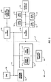
- Figs. 2 and 3 are illustrations of various system configurations of a computer 100 that includes a central processing unit (CPU) 105 that communicates with system memory 110.
- the CPU may be multiple processors connected in parallel, pipelined, or some combination thereof.
- the CPU also communicates on bus 112 with input/output channels or adapters 115 and 120. Through the input/output channels, the CPU may communicate with other computer systems 125, tape drives 130, disk drives 135, or other input/output devices 138 such as optical disks or removable floppy disks.
- System memory 110, tape drives 130, disk drives 135, removable media, etc. are all referred to as memory for storing data to be processed.
- a data compression apparatus or engine is a software implementation permanently stored on a disk drive 135, loaded in system memory 110, and executed by CPU 105 when needed.
- computer 100 may also include a hardware or software compression apparatus 140 on bus 112 that contains compression engine 141 and possibly a decompression engine 142.
- This compression engine may be invoked by a operating system file handler running on the CPU to do compression of data being transmitted or received through the input/output channels.
- the compression engine may utilize system memory 110 or an optional memory 145 while performing the desired compression of data. If optional memory 145 is used, the compressed data may be transmitted directly to and from the I/O channels on optional bus 147.
- Fig. 3 illustrates a computer 150 including a CPU 155 and system memory 160.
- the CPU communicates on bus 162 with input/output channels or adapters 165 and 170. Through the input/output channels, the CPU may communicate with other computer systems 175, tape drives 180, disk drives 185 or other input/output devices 188. Coupled to the input/output channels are compression apparatus 190 and 194 including hardware or software compression engines 191 and 195 and possibly decompression engines 192 and 196 for compressing and/or decompressing some or all data passing through the input/output channels.
- the engine may also have optional memory 198 for working as buffers and for handling space management tasks as the data is compressed.
- one computer system such as a server
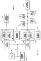
- Fig. 4 is a block diagram illustrating a preferred data compression engine 300.
- the data compression engine is a software implementation which emulates the various elements described below.
- the data compression engine may easily be implemented in hardware.
- the operation of the various elements of the data compression engine are controlled by a control circuit 305 which is coupled to each of the elements described below.
- the control circuit is a logic circuit which operates as a state machine as will be described in greater detail below.
- Data enters the compression engine on input data bus 310 into input data register 320 and is later stored in a previous data buffer 321.
- the input data is an eight bit character.
- An input counter 322 is used to count the total number of input characters received.
- the eight bit data stored in the input data buffer is then used as an address to address history buffer 330 by control circuitry 305.
- the history buffer includes 256 shift registers, each shift register addressable by using the input data in the input data register.
- each shift register contains 512 entries or cells (or some other number, typically two to the Nth power) which indicate when the addressing data for that shift register was previously received and stored in the input data register. That is, a 1 is stored in locations corresponding to when the addressing data for the shift register was previously received and stored in the input data register and a 0 is stored in locations corresponding to when data other than the addressing data for the shift register was previously received and stored in the input data register.
- a last update table 335 has 256 cells, each cell corresponding to one shift register, each cell including the time when each shift register was last updated. This allows any history buffer shift register to be updated only when input data is received that addresses that particular shift register. In an alternative embodiment, the last update table may not be used. However, in that case, all the shift registers in the history buffer will need to be shifted one bit after each input character.
- An OLD register 340 and a NEW register 345 each includes 512 cells in the present example, each cell corresponding to one cell in each history buffer shift register.
- the OLD and NEW registers are used to locate matching strings of data as will be described below with reference to Fig. 5.
- a match counter 350 is used to count the number of input data characters matching a previous string of historical data.
- Figs. 5A-5B are flowcharts illustrating operation of the preferred embodiment of the invention utilizing the structure described in Fig. 4 above.
- the data compression engine is initialized.
- the last update table 335 is loaded with a negative value greater than the length of the shift registers, the input counter 322 is set to negative one (-1) , the OLD and NEW registers 340 and 345 and the match counter 350 are set to zero (0). This is to prevent the compression engine from utilizing random data currently stored in the history buffer for matching strings.
- the last update table 335 may be loaded with negative ones (-1) and the history buffer loaded with zeroes to accomplish initialization.
- the last update table, history buffer, input counter, OLD and NEW registers, and match counter may be preloaded with a desired or previously used history, such as one that is optimized for a particular set or sets of data.
- the last update table, history buffer, input counter, OLD and NEW registers, and match counter contents may be stored to memory for later use when the data compression is continued (i.e. context switching).
- step 410 it is determined whether there is any more input data to be received. If not, then processing continues to step 415 to generate the last data token, a process that will be described in greater detail below in step 458. If yes, then in step 420, the character currently in the input data register 320 is loaded into previous data register 321 and the next character of input data is read and loaded into input data register 320. In step 425, the input counter 322 is incremented by one to indicate that another input character has been received.
- a shift register in the history buffer and a corresponding cell in the last update table are selected by using the input value in the input data register as an address.
- the difference of the input counter value and the value in the selected cell of the last update table is used as a shift count to shift left with zero fill the selected shift register. This is to update the selected shift register to the current time. For example, if the selected shift register has not been updated for 512 cycles in the present example, then the selected shift register will be filled with all zeroes to indicate that lack of a match during the past 512 cycles.
- step 435 it is determined whether the OLD register is all zeroes indicating that no string match is currently in progress. If yes, then processing continues to step 460 described below. If no, then processing continues to step 440 where it is determined whether a maximum length data string match has occurred. That is, data string matches should not exceed, in the preferred embodiment, a maximum length that can be encoded in an output data token. If yes, then in step 445, calculate the starting point, known as displacement, of the matching string using the value in the OLD register (i.e. the location of any ones in the OLD register) and generate and write a token referring to a previous matching string of characters.
- a token referring to a matching previous string of characters starts with a first bit equal to 1 (as opposed to a first bit equal to 0 for a raw or non-matching token) followed by the displacement and length of the matching string. Processing then continues to step 460 described below. If, in step 440, the result was no, then processing continues to step 450.
- step 450 the contents of the OLD register are ANDed with the selected shift register and the result is stored in the NEW register.
- the OLD register and the shift register include 16 thirty-two bit words for a total of 512 bits.
- an index may be generated indicating which words in the shift register contain at least a single one.
- a similar index may be constructed or copied from the shift register for the NEW and then the OLD registers. These indices may be used to limit the AND operation to where there are some ones in corresponding words in both the shift register and the OLD register.
- step 455 it is determined whether the NEW register is all zeroes indicating that the current input character does not continue a matching string of data. If no, then, in step 456, the match counter 350 is incremented by 1 and processing continues to step 480 described below.
- step 458 a token is calculated, generated and written to output. If the value in match counter 450 is one, this indicates that the input data stored in the previous data register 321 started a matching string that did not continue with the data character stored in the input data register. If so, then a raw token is generated as described that starts with a first bit equal to zero followed by the input character (8 bits in the present example) located in the previous data register. Otherwise, a compressed data token is generated as described in step 445 above that includes the displacement and length of the matching string. Processing then continues to step 460.
- step 460 copy the contents of the selected shift register to the NEW register.
- step 465 it is determined whether the contents of the NEW register is all zeroes, indicating whether the data character in the input data register has been received before during the past 512 cycles. If no, then in step 470 the match counter is set to one indicating the start of a new matching string and processing continues to step 480 described below. If yes in step 465, then processing continues to step 475.
- step 475 the data in the input data register is encoded as a raw data token.
- step 480 the right most bit of the selected shift register is set to 1 indicating the receipt of the input data in the input data register.
- the contents of the NEW register is moved to the OLD register.
- this may be easily performed by using an OLD register pointer that will alternately point to the two registers used as the OLD and NEW registers such that the NEW register becomes the OLD register and visa versa for each input character.
- the actual data in the NEW register does not have to be moved to the OLD register. Instead the pointer to the OLD register is pointed to the previous NEW register. Processing then returns to step 410.
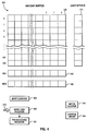
- Figs. 6A-6F are block diagrams illustrating an example input data stream being compressed using the structure illustrated in Fig. 4 above.
- the history buffer is eight bits wide with three possible entries, A, B and C.
- the input data stream is [A B A B C].
- Fig. 6A illustrates the various elements of the compression engine after the engine is initialized.
- a history buffer 530 is left with random numbers while the last update table is set to all -8 (negative the number of entries in each shift register of the history buffer).
- the OLD and NEW registers 540 and 545 and the match counter 550 are set to 0.
- the input counter 522 is set to -1.
- the input data register and previous data registers 520 and 521 are left with random numbers as no data has been received yet.
- Fig. 6B illustrates the various elements of the compression engine after the first character A has been received.
- the input counter has been incremented and the shift register for A has been updated.
- the OLD register indicates that no match has occurred yet.
- a raw token was generated that read as (0,A).
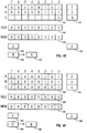
- Fig. 6C illustrates the various elements of the compression engine after the second character B has been received.
- the input counter has been incremented and the shift register for B has been updated.
- the OLD register indicates that no match has occurred yet.
- a raw token was generated that read as (0,B).
- Fig. 6D illustrates the various elements of the compression engine after the third character A has been received.
- the input counter has been incremented and the shift register for A has been updated.
- the OLD register and the match counter indicate that a match has occurred. No tokens were generated.
- Fig. 6E illustrates the various elements of the compression engine after the fourth character B has been received.
- the input counter has been incremented and the shift register for B has been updated.
- the OLD register and the match counter indicate that a match is continuing. No tokens were generated.
- Fig. 6F illustrates the various elements of the compression engine after the fifth character C has been received.
- the input counter has been incremented and the shift register for C has been updated.
- the OLD register indicates that no match is occurring.
- a compressed word token was generated that read as (1, 0, 2) referencing the previous matching string of A and B starting at time 0 with length 2. Due to C being the last input character, a raw token was also generated that read as (0,C)
- [A B A B C] is encoded as [(0,A) (0,B) (1,0,2) (0,C)].
- An optional unit may be included in an alternative embodiment of the invention to allow the compression engine to compress data to typical Lempel-Ziv form that utilizes relational addresses as described in Figs. 1A-1C.
- An addition circuit would be used to convert the fixed address to a relational address by adding the value in the match counter from the relational address.
- the addition circuit could also be included but disabled when compressing data in a fixed address format
- a raw word token is generated as a 0 followed by the raw word.
- a compressed word token is passed as a 1 followed by the length of the matching string and the starting location of the matching string in the CAM array (called the displacement).
- a control token may also be generated which starts with eight 1's and is followed with four bits designating the control instructions.
- an end token is passed to designate the end of a compressed data stream. The end token is thirteen 1's in a row.
- Table 1 shows the codes used in the preferred embodiment to designate the length of a compressed data word string.
- This type of coding is a modified logarithmic coding wherein shorter strings utilize shorter codes and longer strings utilize longer codes. This is a useful coding technique when the frequency of shorter strings is substantially greater than the frequency of longer strings.
- the displacement is specified with an 11 bit value in the preferred embodiment. A shorter displacement may be used with a CAM array having fewer sections.
- control instructions may be passed in the compressed data stream.
- These control instructions may include instructions such as reset the history buffer, preload the history buffer with a preferred data set, etc.
- control instructions there are two types of control instructions, long and short.
- Table 2 illustrates long control instructions wherein a 12 bit control field is given followed by an 11 bit control subfield. This provides for 2048 subfields for each of the four control fields for a total of 8208 possible long instructions.
- Table 3 illustrates the short control instructions.
- the short control instructions are only 12 bits long and are, therefore, fewer in number than the total number of long control instruction. However, the short control instructions require less time to transmit.
- one short control field has already been defined as an end marker.
- the end marker is a 1 (defining the following bits as being either a compressed data token or as a control instruction) followed by the twelve bit end marker control instruction (twelve 1s).
- a history buffer is used that does not store the actual historical data to be searched, but rather uses the historical data as addresses to shift registers with each shift register storing bits located where the historical data was previously encountered. This significantly decreases the search overhead requirements for each word operation while performing an exhaustive string matching process. As a result, compression is performed more quickly and efficiently.
- the compression is more effective than many existing Lempel-Ziv techniques because the search for matching data strings is exhaustive. That is, the history buffer allows for an exhaustive search for all possible matching strings. Many existing techniques use a compromising technique such as hashing in order to reduce the search time but which may not find the longest matching string in memory.
- data words including multiple data bytes or partial data bytes may be sequentially compressed utilizing the apparatus and method described above.
Abstract
An apparatus for compressing data includes apparatus for using a received data element as an address to a location in a memory, apparatus for determining whether the addressed memory location contains a first record of a first matching data element, and apparatus for generating a pointer to the first matching data element. The memory acts as a history buffer which does not store the actual historical data to be searched, but rather uses input data as an address into memory, thereby decreasing searching overheads.
Description
- The present invention is directed to a method and apparatus for compressing and decompressing data, particularly for sequential data compression and decompression.
- Many types of data compression systems exist. One commonly used technique is the Lempel-Ziv algorithm which is described in "Compression of Individual Sequences via variable Rate Coding" by Lempel and Ziv in IEEE Transactions on Information Theory, Sept., 1977, pages 530-536. Figs. 1A-1C illustrate a typical implementation of the Lempel-Ziv algorithm. In Fig. 1A, a
shift register 10 that is N+1 bytes long is used to temporarily store previously processed data. If new data to be processed includes a string of data bytes that have been processed before, then a token including the length and relative address of the previously processed data string in the shift register will be generated. This can in general be expressed using fewer bits of information than the data string itself, so the data string is effectively compressed. If the data to be processed does not form part of a previous data string existing in the shift register, then a token or tokens will be generated containing this data explicitly. In general, such tokens have to be expressed using slightly more bits of information than the data itself, so there is an effective expansion. Overall, the gain from the compressed data strings usually exceeds the losses from the non-compressed data strings, so overall data compression results. If there are no repeating strings of data in a data stream, then the data stream can not be compressed by this technique. - Fig. 1B illustrates the generation of a token referencing previously processed data. In the example given, the values A, B, C and D were previously processed and are currently stored in the shift register at
addresses relative address 37. The address is relative because once a token is generated describing the string, the values A, B, and C will be loaded into the shift register and the values A, B, C and D will be shifted down the shift register to a new address. The address of data in the shift register is relative to the number of data values subsequently processed. - Fig. 1C illustrates the generation of a second token referencing previously stored data. In the example given, the values A, B, C and Z are to be processed. The new data includes the string ABC that has a length of 3 and matches previously stored string ABC at
relative addresses - One of the primary problems with implementations of the Lempel-Ziv compression technique is the difficulty in performing the search operation for previous matching strings at an effective processing speed. Many techniques discussed below are modifications of the Lempel-Ziv technique that attempt to improve the speed of the technique by improving the speed of the search operation or the amount of compression achieved by using more efficient token encoding.
- U.S. Patent 4,558,302 teaches what is commonly called a Lempel-Ziv-Welch data compression technique. This patent discloses utilizing a dictionary for storing commonly used data strings and searching that dictionary using bashing techniques.
- U.S. Patent 4,876,541 is directed to improvements to the Lempel-Ziv-Welch data compression technique described above by using a matching algorithm.
- U.S. Patent Application Serial No. 07/807,007, filed December 13, 1991, entitled "METHOD AND APPARATUS FOR COMPRESSING DATA", assigned to International Business Machines Corporation (EP 546863) teaches a modification to the Lempel-Ziv compression technique where the history buffer data is stored in a fixed location rather than a shift register. As a result, the tokens used to refer to previously compressed data refer to data in a fixed location rather than to data moving along a shift register.
- A major difficulty with prior art implementations of Lempel-Ziv type data compression techniques is the use of a relative addressing scheme. Such a scheme requires the use of a shift register to hold previously processed data words, one word in each data element. Each incoming data word is shifted into the first position of the shift register while all the previously processed data words are shifted into adjacent positions. In addition, a random access capability is required to each element of the shift register. This requires much more circuitry, chip area, and power to implement than a simple random access memory.
- Another major difficulty with prior art implementations of Lempel-Ziv data compression techniques is the storage and/or movement of historical data that is subsequently searched for providing tokens that refer to the historical data.
- Accordingly, the invention provides apparatus for compressing data comprising:
means for using a received data element as an address to a location in a memory;
means for determining whether the addressed memory location contains a first matching data element; and
means for generating a pointer to the first matching data element. - In a preferred embodiment, the means for using a received data element further includes means for using a second received data element as a second address to a second location in the memory; the means for determining includes means for determining whether the second addressed location of the memory includes a second matching data element contiguous to the first matching data element; and the means for using a received data element as an address to a location in a memory includes means for using a received data element as an address to one of a plurality of shift registers.
- The invention also provides a method for compressing data comprising the steps of:
using a received data element as an address to a location in a memory;
determining whether the addressed memory location contains a first record of a first matching data element; and
generating a pointer to the first matching data element. - Thus the data compression apparatus uses a received data element as an address to a location in a memory, determines whether the addressed memory location contains a first record of a first matching data element, and generates a pointer to the first matching data element. The history buffer does not store the actual historical data to be searched, but rather uses input data as addresses to shift registers with each shift register storing bits whose location indicates when historical data matching the address of the shift register was previously encountered. This significantly decreases the search overhead requirements for each word operation while performing an exhaustive string matching process. This improves the compression ratio, as well as allowing very fast throughput.
- An embodiment of the invention will now be described in detail by way of example only, with reference to the following drawings:
- Figs. 1A-1C are diagrams of a prior art technique for compressing data;
- Figs. 2 and 3 are illustrations of various system configurations including data compression apparatus;
- Fig. 4 is a block diagram illustrating data compression apparatus in accordance with the present invention;
- Fig. 5A-5B are flowcharts illustrating operation of the data compression apparatus described in Fig. 4; and
- Figs. 6A-6F are block diagrams illustrating an example input data stream being compressed using the data compression apparatus illustrated in Fig. 4.
- Figs. 2 and 3 are illustrations of various system configurations of a
computer 100 that includes a central processing unit (CPU) 105 that communicates withsystem memory 110. The CPU may be multiple processors connected in parallel, pipelined, or some combination thereof. The CPU also communicates onbus 112 with input/output channels oradapters other computer systems 125, tape drives 130, disk drives 135, or other input/output devices 138 such as optical disks or removable floppy disks.System memory 110, tape drives 130, disk drives 135, removable media, etc. are all referred to as memory for storing data to be processed. In the preferred embodiment, a data compression apparatus or engine is a software implementation permanently stored on adisk drive 135, loaded insystem memory 110, and executed byCPU 105 when needed. In an alternative embodiment,computer 100 may also include a hardware orsoftware compression apparatus 140 onbus 112 that containscompression engine 141 and possibly adecompression engine 142. This compression engine may be invoked by a operating system file handler running on the CPU to do compression of data being transmitted or received through the input/output channels. The compression engine may utilizesystem memory 110 or anoptional memory 145 while performing the desired compression of data. Ifoptional memory 145 is used, the compressed data may be transmitted directly to and from the I/O channels onoptional bus 147. - Fig. 3 illustrates a
computer 150 including aCPU 155 andsystem memory 160. The CPU communicates onbus 162 with input/output channels oradapters 165 and 170. Through the input/output channels, the CPU may communicate withother computer systems 175, tape drives 180,disk drives 185 or other input/output devices 188. Coupled to the input/output channels arecompression apparatus software compression engines engines optional memory 198 for working as buffers and for handling space management tasks as the data is compressed. - There are many other possible system configurations that are apparent to those of ordinary skill in the art. For example, one computer system, such as a server, may include a data compression engine for compressing all data sent to it while the remaining computer systems may each include a decompression engine to decompress all data they receive from the server.
- Fig. 4 is a block diagram illustrating a preferred
data compression engine 300. In the preferred embodiment, the data compression engine is a software implementation which emulates the various elements described below. In an alternative embodiment, the data compression engine may easily be implemented in hardware. The operation of the various elements of the data compression engine are controlled by acontrol circuit 305 which is coupled to each of the elements described below. The control circuit is a logic circuit which operates as a state machine as will be described in greater detail below. Data enters the compression engine oninput data bus 310 into input data register 320 and is later stored in aprevious data buffer 321. In the preferred embodiment, the input data is an eight bit character. Aninput counter 322 is used to count the total number of input characters received. The eight bit data stored in the input data buffer is then used as an address to addresshistory buffer 330 bycontrol circuitry 305. The history buffer includes 256 shift registers, each shift register addressable by using the input data in the input data register. In the present example, each shift register contains 512 entries or cells (or some other number, typically two to the Nth power) which indicate when the addressing data for that shift register was previously received and stored in the input data register. That is, a 1 is stored in locations corresponding to when the addressing data for the shift register was previously received and stored in the input data register and a 0 is stored in locations corresponding to when data other than the addressing data for the shift register was previously received and stored in the input data register. In the preferred embodiment, a last update table 335 has 256 cells, each cell corresponding to one shift register, each cell including the time when each shift register was last updated. This allows any history buffer shift register to be updated only when input data is received that addresses that particular shift register. In an alternative embodiment, the last update table may not be used. However, in that case, all the shift registers in the history buffer will need to be shifted one bit after each input character. - An
OLD register 340 and aNEW register 345 each includes 512 cells in the present example, each cell corresponding to one cell in each history buffer shift register. The OLD and NEW registers are used to locate matching strings of data as will be described below with reference to Fig. 5. Amatch counter 350 is used to count the number of input data characters matching a previous string of historical data. - Figs. 5A-5B are flowcharts illustrating operation of the preferred embodiment of the invention utilizing the structure described in Fig. 4 above. In a
first step 400, the data compression engine is initialized. In the preferred embodiment, the last update table 335 is loaded with a negative value greater than the length of the shift registers, theinput counter 322 is set to negative one (-1) , the OLD andNEW registers match counter 350 are set to zero (0). This is to prevent the compression engine from utilizing random data currently stored in the history buffer for matching strings. In an alternative embodiment, the last update table 335 may be loaded with negative ones (-1) and the history buffer loaded with zeroes to accomplish initialization. In another alternative embodiment, the last update table, history buffer, input counter, OLD and NEW registers, and match counter may be preloaded with a desired or previously used history, such as one that is optimized for a particular set or sets of data. In cases where the compression engine may be interrupted with other compression tasks, the last update table, history buffer, input counter, OLD and NEW registers, and match counter contents may be stored to memory for later use when the data compression is continued (i.e. context switching). - In
step 410, it is determined whether there is any more input data to be received. If not, then processing continues to step 415 to generate the last data token, a process that will be described in greater detail below instep 458. If yes, then instep 420, the character currently in the input data register 320 is loaded into previous data register 321 and the next character of input data is read and loaded into input data register 320. Instep 425, theinput counter 322 is incremented by one to indicate that another input character has been received. - In
step 430, a shift register in the history buffer and a corresponding cell in the last update table are selected by using the input value in the input data register as an address. The difference of the input counter value and the value in the selected cell of the last update table is used as a shift count to shift left with zero fill the selected shift register. This is to update the selected shift register to the current time. For example, if the selected shift register has not been updated for 512 cycles in the present example, then the selected shift register will be filled with all zeroes to indicate that lack of a match during the past 512 cycles. - In
step 435, it is determined whether the OLD register is all zeroes indicating that no string match is currently in progress. If yes, then processing continues to step 460 described below. If no, then processing continues to step 440 where it is determined whether a maximum length data string match has occurred. That is, data string matches should not exceed, in the preferred embodiment, a maximum length that can be encoded in an output data token. If yes, then instep 445, calculate the starting point, known as displacement, of the matching string using the value in the OLD register (i.e. the location of any ones in the OLD register) and generate and write a token referring to a previous matching string of characters. In the preferred embodiment, a token referring to a matching previous string of characters starts with a first bit equal to 1 (as opposed to a first bit equal to 0 for a raw or non-matching token) followed by the displacement and length of the matching string. Processing then continues to step 460 described below. If, instep 440, the result was no, then processing continues to step 450. - In
step 450, the contents of the OLD register are ANDed with the selected shift register and the result is stored in the NEW register. In the preferred embodiment, the OLD register and the shift register include 16 thirty-two bit words for a total of 512 bits. Duringstep 430 above, an index may be generated indicating which words in the shift register contain at least a single one. In addition, duringsteps step 455, it is determined whether the NEW register is all zeroes indicating that the current input character does not continue a matching string of data. If no, then, instep 456, thematch counter 350 is incremented by 1 and processing continues to step 480 described below. - If the answer to step 455 is yes, indicating that a previously matching string is discontinued with the current input character, then processing continues to step 458. In
step 458, a token is calculated, generated and written to output. If the value inmatch counter 450 is one, this indicates that the input data stored in the previous data register 321 started a matching string that did not continue with the data character stored in the input data register. If so, then a raw token is generated as described that starts with a first bit equal to zero followed by the input character (8 bits in the present example) located in the previous data register. Otherwise, a compressed data token is generated as described instep 445 above that includes the displacement and length of the matching string. Processing then continues to step 460. - In
step 460, copy the contents of the selected shift register to the NEW register. Instep 465, it is determined whether the contents of the NEW register is all zeroes, indicating whether the data character in the input data register has been received before during the past 512 cycles. If no, then instep 470 the match counter is set to one indicating the start of a new matching string and processing continues to step 480 described below. If yes instep 465, then processing continues to step 475. Instep 475, the data in the input data register is encoded as a raw data token. Instep 480, the right most bit of the selected shift register is set to 1 indicating the receipt of the input data in the input data register. In addition, the contents of the NEW register is moved to the OLD register. In the preferred embodiment, this may be easily performed by using an OLD register pointer that will alternately point to the two registers used as the OLD and NEW registers such that the NEW register becomes the OLD register and visa versa for each input character. As a result, the actual data in the NEW register does not have to be moved to the OLD register. Instead the pointer to the OLD register is pointed to the previous NEW register. Processing then returns to step 410. - Figs. 6A-6F are block diagrams illustrating an example input data stream being compressed using the structure illustrated in Fig. 4 above. In the present example, the history buffer is eight bits wide with three possible entries, A, B and C. The input data stream is [A B A B C]. Fig. 6A illustrates the various elements of the compression engine after the engine is initialized. A
history buffer 530 is left with random numbers while the last update table is set to all -8 (negative the number of entries in each shift register of the history buffer). The OLD andNEW registers match counter 550 are set to 0. Theinput counter 522 is set to -1. The input data register andprevious data registers - Fig. 6B illustrates the various elements of the compression engine after the first character A has been received. The input counter has been incremented and the shift register for A has been updated. The OLD register indicates that no match has occurred yet. A raw token was generated that read as (0,A).
- Fig. 6C illustrates the various elements of the compression engine after the second character B has been received. The input counter has been incremented and the shift register for B has been updated. The OLD register indicates that no match has occurred yet. A raw token was generated that read as (0,B).
- Fig. 6D illustrates the various elements of the compression engine after the third character A has been received. The input counter has been incremented and the shift register for A has been updated. The OLD register and the match counter indicate that a match has occurred. No tokens were generated.
- Fig. 6E illustrates the various elements of the compression engine after the fourth character B has been received. The input counter has been incremented and the shift register for B has been updated. The OLD register and the match counter indicate that a match is continuing. No tokens were generated.
- Fig. 6F illustrates the various elements of the compression engine after the fifth character C has been received. The input counter has been incremented and the shift register for C has been updated. The OLD register indicates that no match is occurring. A compressed word token was generated that read as (1, 0, 2) referencing the previous matching string of A and B starting at
time 0 withlength 2. Due to C being the last input character, a raw token was also generated that read as (0,C) - As a result of this example, [A B A B C] is encoded as [(0,A) (0,B) (1,0,2) (0,C)].
- An optional unit may be included in an alternative embodiment of the invention to allow the compression engine to compress data to typical Lempel-Ziv form that utilizes relational addresses as described in Figs. 1A-1C. An addition circuit would be used to convert the fixed address to a relational address by adding the value in the match counter from the relational address. The addition circuit could also be included but disabled when compressing data in a fixed address format
- In the preferred embodiment, a raw word token is generated as a 0 followed by the raw word. A compressed word token is passed as a 1 followed by the length of the matching string and the starting location of the matching string in the CAM array (called the displacement). A control token may also be generated which starts with eight 1's and is followed with four bits designating the control instructions. Finally, an end token is passed to designate the end of a compressed data stream. The end token is thirteen 1's in a row.
- Table 1 shows the codes used in the preferred embodiment to designate the length of a compressed data word string. This type of coding is a modified logarithmic coding wherein shorter strings utilize shorter codes and longer strings utilize longer codes. This is a useful coding technique when the frequency of shorter strings is substantially greater than the frequency of longer strings. The displacement is specified with an 11 bit value in the preferred embodiment. A shorter displacement may be used with a CAM array having fewer sections.
TABLE 1 Codes Used to Designate Compressed Word Length Code Field Compressed Word Length 00 2 words 01 3 words 10 00 4 words 10 01 5 words 10 10 6 words 10 11 7 words 110 000 8 words ... ... ... ... ... ... ... ... 110 111 15 words 1110 0000 16 words .... .... ... ... .... .... ... ... 1110 1111 31 words 1111 0000 0000 32 words .... .... .... ... ... .... .... .... ... ... 1111 1110 1111 271 words - In order to provide for future expansion of the invention, control instructions may be passed in the compressed data stream. These control instructions may include instructions such as reset the history buffer, preload the history buffer with a preferred data set, etc. In the preferred embodiment, there are two types of control instructions, long and short. Table 2 illustrates long control instructions wherein a 12 bit control field is given followed by an 11 bit control subfield. This provides for 2048 subfields for each of the four control fields for a total of 8208 possible long instructions.
TABLE 2 Long Instruction Control Fields and Subfields Long Control Field Control Subfield 1111 1111 0000 0000 0000 000 - 1111 1111 111 1111 1111 0001 0000 0000 000 - 1111 1111 111 1111 1111 0010 0000 0000 000 - 1111 1111 111 1111 1111 0011 0000 0000 000 - 1111 1111 111 - Table 3 illustrates the short control instructions. The short control instructions are only 12 bits long and are, therefore, fewer in number than the total number of long control instruction. However, the short control instructions require less time to transmit. As described above, one short control field has already been defined as an end marker. The end marker is a 1 (defining the following bits as being either a compressed data token or as a control instruction) followed by the twelve bit end marker control instruction (twelve 1s).
TABLE 3 Short Instruction Control Fields Control Field Current Function 1111 1111 0100 not defined 1111 1111 0101 not defined 1111 1111 0110 not defined .... .... .... ... ....... .... .... .... ... ....... 1111 1111 1110 not defined 1111 1111 1111 end marker - Thus a history buffer is used that does not store the actual historical data to be searched, but rather uses the historical data as addresses to shift registers with each shift register storing bits located where the historical data was previously encountered. This significantly decreases the search overhead requirements for each word operation while performing an exhaustive string matching process. As a result, compression is performed more quickly and efficiently.
- The compression is more effective than many existing Lempel-Ziv techniques because the search for matching data strings is exhaustive. That is, the history buffer allows for an exhaustive search for all possible matching strings. Many existing techniques use a compromising technique such as hashing in order to reduce the search time but which may not find the longest matching string in memory.
- Variations on the above embodiments will be apparent to those of ordinary skill in the art. For example, data words including multiple data bytes or partial data bytes may be sequentially compressed utilizing the apparatus and method described above.
Claims (10)
- Apparatus for compressing data comprising:
means for using a received data element as an address to a location in a memory;
means for determining whether the addressed memory location contains a first matching data element; and
means for generating a pointer to the first matching data element. - The apparatus of Claim 1 wherein the means for using a received data element further includes means for using a second received data element as a second address to a second location in the memory.
- The apparatus of Claim 2 wherein the means for determining includes means for determining whether the second addressed location of the memory includes a second matching data element contiguous to the first matching data element.
- The apparatus of any preceding Claim wherein the means for using a received data element as an address to a location in a memory includes means for using a received data element as an address to one of a plurality of shift registers.
- A data processing system comprising:
a memory for storing data;
a processor for processing data;
and data compression apparatus according to any preceding claim. - A method for compressing data comprising the steps of:
using a received data element as an address to a location in a memory;
determining whether the addressed memory location contains a first record of a first matching data element; and
generating a pointer to the first matching data element. - The method of Claim 6 wherein the step of using a received data element further includes using a second received data element as a second address to a second location in the memory.
- The method of Claim 7 wherein the step of determining includes determining whether the second addressed location of the memory includes a second matching data element contiguous to the first matching data element.
- The method of Claim 8 wherein the step of generating includes generating a pointer to the first and second matching data elements.
- The method of any of Claims 6 to 9 wherein the step of using a received data element as an address to a location in a memory includes using a received data element as an address to one of a plurality of shift registers.
Applications Claiming Priority (2)
| Application Number | Priority Date | Filing Date | Title |
|---|---|---|---|
| US173738 | 1993-12-23 | ||
| US08/173,738 US5563595A (en) | 1993-12-23 | 1993-12-23 | Method and apparatus for compressing data |
Publications (2)
| Publication Number | Publication Date |
|---|---|
| EP0660531A2 true EP0660531A2 (en) | 1995-06-28 |
| EP0660531A3 EP0660531A3 (en) | 1996-02-07 |
Family
ID=22633277
Family Applications (1)
| Application Number | Title | Priority Date | Filing Date |
|---|---|---|---|
| EP94308515A Withdrawn EP0660531A3 (en) | 1993-12-23 | 1994-11-17 | Method and apparatus for compressing data. |
Country Status (4)
| Country | Link |
|---|---|
| US (1) | US5563595A (en) |
| EP (1) | EP0660531A3 (en) |
| JP (1) | JP2534465B2 (en) |
| CA (1) | CA2132762C (en) |
Cited By (2)
| Publication number | Priority date | Publication date | Assignee | Title |
|---|---|---|---|---|
| WO1997040581A1 (en) * | 1996-04-18 | 1997-10-30 | Milto, Jury Petrovich | Binary code compression and decompression and parallel compression and decompression processor |
| US5771011A (en) * | 1996-07-15 | 1998-06-23 | International Business Machines Corporation | Match detect logic for multi-byte per cycle hardware data compression |
Families Citing this family (34)
| Publication number | Priority date | Publication date | Assignee | Title |
|---|---|---|---|---|
| US6170047B1 (en) | 1994-11-16 | 2001-01-02 | Interactive Silicon, Inc. | System and method for managing system memory and/or non-volatile memory using a memory controller with integrated compression and decompression capabilities |
| US7190284B1 (en) | 1994-11-16 | 2007-03-13 | Dye Thomas A | Selective lossless, lossy, or no compression of data based on address range, data type, and/or requesting agent |
| US6002411A (en) | 1994-11-16 | 1999-12-14 | Interactive Silicon, Inc. | Integrated video and memory controller with data processing and graphical processing capabilities |
| US5745734A (en) * | 1995-09-29 | 1998-04-28 | International Business Machines Corporation | Method and system for programming a gate array using a compressed configuration bit stream |
| US5974471A (en) * | 1996-07-19 | 1999-10-26 | Advanced Micro Devices, Inc. | Computer system having distributed compression and decompression logic for compressed data movement |
| US5798718A (en) * | 1997-05-12 | 1998-08-25 | Lexmark International, Inc. | Sliding window data compression method and apparatus |
| US6879266B1 (en) | 1997-08-08 | 2005-04-12 | Quickshift, Inc. | Memory module including scalable embedded parallel data compression and decompression engines |
| US6279016B1 (en) | 1997-09-21 | 2001-08-21 | Microsoft Corporation | Standardized filtering control techniques |
| US6216175B1 (en) * | 1998-06-08 | 2001-04-10 | Microsoft Corporation | Method for upgrading copies of an original file with same update data after normalizing differences between copies created during respective original installations |
| US6141743A (en) * | 1998-09-17 | 2000-10-31 | Advanced Micro Devices, Inc. | Token-based storage for general purpose processing |
| US7538694B2 (en) * | 1999-01-29 | 2009-05-26 | Mossman Holdings Llc | Network device with improved storage density and access speed using compression techniques |
| US6145069A (en) * | 1999-01-29 | 2000-11-07 | Interactive Silicon, Inc. | Parallel decompression and compression system and method for improving storage density and access speed for non-volatile memory and embedded memory devices |
| US6819271B2 (en) | 1999-01-29 | 2004-11-16 | Quickshift, Inc. | Parallel compression and decompression system and method having multiple parallel compression and decompression engines |
| US6208273B1 (en) | 1999-01-29 | 2001-03-27 | Interactive Silicon, Inc. | System and method for performing scalable embedded parallel data compression |
| US7129860B2 (en) * | 1999-01-29 | 2006-10-31 | Quickshift, Inc. | System and method for performing scalable embedded parallel data decompression |
| US6822589B1 (en) | 1999-01-29 | 2004-11-23 | Quickshift, Inc. | System and method for performing scalable embedded parallel data decompression |
| US6885319B2 (en) * | 1999-01-29 | 2005-04-26 | Quickshift, Inc. | System and method for generating optimally compressed data from a plurality of data compression/decompression engines implementing different data compression algorithms |
| US6466999B1 (en) | 1999-03-31 | 2002-10-15 | Microsoft Corporation | Preprocessing a reference data stream for patch generation and compression |
| US6879988B2 (en) | 2000-03-09 | 2005-04-12 | Pkware | System and method for manipulating and managing computer archive files |
| US20050015608A1 (en) | 2003-07-16 | 2005-01-20 | Pkware, Inc. | Method for strongly encrypting .ZIP files |
| US8959582B2 (en) | 2000-03-09 | 2015-02-17 | Pkware, Inc. | System and method for manipulating and managing computer archive files |
| US20030009595A1 (en) * | 2001-07-09 | 2003-01-09 | Roger Collins | System and method for compressing data using field-based code word generation |
| US7064688B2 (en) * | 2001-07-09 | 2006-06-20 | Good Technology, Inc. | System and method for compressing data on a bandwidth-limited network |
| US7743119B2 (en) | 2001-08-07 | 2010-06-22 | Motorola, Inc. | System and method for mapping identification codes |
| US7596565B2 (en) * | 2001-08-07 | 2009-09-29 | Good Technology | System and method for maintaining wireless file folders at a wireless device |
| US7243163B1 (en) * | 2001-08-07 | 2007-07-10 | Good Technology, Inc. | System and method for full wireless synchronization of a data processing apparatus with a messaging system |
| US7962622B2 (en) * | 2001-08-07 | 2011-06-14 | Motorola Mobility, Inc. | System and method for providing provisioning and upgrade services for a wireless device |
| US7155483B1 (en) | 2001-08-07 | 2006-12-26 | Good Technology, Inc. | Apparatus and method for conserving bandwidth by batch processing data transactions |
| US7085996B2 (en) * | 2001-10-18 | 2006-08-01 | International Business Corporation | Apparatus and method for source compression and comparison |
| US7447799B2 (en) * | 2002-04-24 | 2008-11-04 | Good Technology, Inc. | System and method for automatically updating a wireless device |
| US9813514B2 (en) | 2002-06-12 | 2017-11-07 | Good Technology Holdings Limited | Information repository system including a wireless device and related method |
| US8516034B1 (en) | 2002-07-08 | 2013-08-20 | Good Technology Software, Inc | System and method for modifying application behavior based on network bandwidth |
| US7853578B1 (en) * | 2005-12-09 | 2010-12-14 | Marvell International Ltd. | High-performance pattern matching |
| US7620392B1 (en) | 2006-02-27 | 2009-11-17 | Good Technology, Inc. | Method and system for distributing and updating software in wireless devices |
Citations (2)
| Publication number | Priority date | Publication date | Assignee | Title |
|---|---|---|---|---|
| EP0380294A1 (en) * | 1989-01-23 | 1990-08-01 | Codex Corporation | String matching |
| US5150430A (en) * | 1991-03-15 | 1992-09-22 | The Board Of Trustees Of The Leland Stanford Junior University | Lossless data compression circuit and method |
Family Cites Families (53)
| Publication number | Priority date | Publication date | Assignee | Title |
|---|---|---|---|---|
| US3914586A (en) * | 1973-10-25 | 1975-10-21 | Gen Motors Corp | Data compression method and apparatus |
| US4021782A (en) * | 1974-01-07 | 1977-05-03 | Hoerning John S | Data compaction system and apparatus |
| US4054951A (en) * | 1976-06-30 | 1977-10-18 | International Business Machines Corporation | Data expansion apparatus |
| US4087788A (en) * | 1977-01-14 | 1978-05-02 | Ncr Canada Ltd - Ncr Canada Ltee | Data compression system |
| US4321668A (en) * | 1979-01-02 | 1982-03-23 | Honeywell Information Systems Inc. | Prediction of number of data words transferred and the cycle at which data is available |
| US4463342A (en) * | 1979-06-14 | 1984-07-31 | International Business Machines Corporation | Method and means for carry-over control in the high order to low order pairwise combining of digits of a decodable set of relatively shifted finite number strings |
| US4286256A (en) * | 1979-11-28 | 1981-08-25 | International Business Machines Corporation | Method and means for arithmetic coding utilizing a reduced number of operations |
| US4295125A (en) * | 1980-04-28 | 1981-10-13 | International Business Machines Corporation | Method and means for pipeline decoding of the high to low order pairwise combined digits of a decodable set of relatively shifted finite number of strings |
| US4467317A (en) * | 1981-03-30 | 1984-08-21 | International Business Machines Corporation | High-speed arithmetic compression coding using concurrent value updating |
| US4464650A (en) * | 1981-08-10 | 1984-08-07 | Sperry Corporation | Apparatus and method for compressing data signals and restoring the compressed data signals |
| US4560976A (en) * | 1981-10-15 | 1985-12-24 | Codex Corporation | Data compression |
| US4622545A (en) * | 1982-09-30 | 1986-11-11 | Apple Computer, Inc. | Method and apparatus for image compression and manipulation |
| NL8301264A (en) * | 1983-04-11 | 1984-11-01 | Philips Nv | REGULAR COMPRESSION DEVICE FOR COMPRESSING BINARY DATA OF AN IMAGE AND SCAN DEVICE FOR A DOCUMENT PROVIDED FOR COMPRESSING SUCH. |
| US4677649A (en) * | 1983-04-26 | 1987-06-30 | Canon Kabushiki Kaisha | Data receiving apparatus |
| US4814746A (en) * | 1983-06-01 | 1989-03-21 | International Business Machines Corporation | Data compression method |
| US4558302A (en) * | 1983-06-20 | 1985-12-10 | Sperry Corporation | High speed data compression and decompression apparatus and method |
| JPH0828053B2 (en) * | 1983-08-08 | 1996-03-21 | 株式会社日立製作所 | Data recording method |
| US4633490A (en) * | 1984-03-15 | 1986-12-30 | International Business Machines Corporation | Symmetrical optimized adaptive data compression/transfer/decompression system |
| US4612532A (en) * | 1984-06-19 | 1986-09-16 | Telebyte Corportion | Data compression apparatus and method |
| GB2172127B (en) * | 1985-03-06 | 1988-10-12 | Ferranti Plc | Data compression system |
| US4667649A (en) * | 1985-05-20 | 1987-05-26 | Humphrey Stanley A | Archery bow |
| US4682150A (en) * | 1985-12-09 | 1987-07-21 | Ncr Corporation | Data compression method and apparatus |
| US4652856A (en) * | 1986-02-04 | 1987-03-24 | International Business Machines Corporation | Multiplication-free multi-alphabet arithmetic code |
| US4935882A (en) * | 1986-09-15 | 1990-06-19 | International Business Machines Corporation | Probability adaptation for arithmetic coders |
| US4905297A (en) * | 1986-09-15 | 1990-02-27 | International Business Machines Corporation | Arithmetic coding encoder and decoder system |
| US4891643A (en) * | 1986-09-15 | 1990-01-02 | International Business Machines Corporation | Arithmetic coding data compression/de-compression by selectively employed, diverse arithmetic coding encoders and decoders |
| US4730348A (en) * | 1986-09-19 | 1988-03-08 | Adaptive Computer Technologies | Adaptive data compression system |
| JPH0815263B2 (en) * | 1986-12-12 | 1996-02-14 | 株式会社日立製作所 | Data compression / decompression method |
| US4853696A (en) * | 1987-04-13 | 1989-08-01 | University Of Central Florida | Code converter for data compression/decompression |
| US4943869A (en) * | 1987-05-06 | 1990-07-24 | Fuji Photo Film Co., Ltd. | Compression method for dot image data |
| US4876541A (en) * | 1987-10-15 | 1989-10-24 | Data Compression Corporation | Stem for dynamically compressing and decompressing electronic data |
| US4891784A (en) * | 1988-01-08 | 1990-01-02 | Hewlett-Packard Company | High capacity tape drive transparently writes and reads large packets of blocked data between interblock gaps |
| US4906991A (en) * | 1988-04-29 | 1990-03-06 | Xerox Corporation | Textual substitution data compression with finite length search windows |
| US4899147A (en) * | 1988-06-03 | 1990-02-06 | Unisys Corporation | Data compression/decompression apparatus with throttle, start-up and backward read controls |
| US5016009A (en) * | 1989-01-13 | 1991-05-14 | Stac, Inc. | Data compression apparatus and method |
| US5003307A (en) * | 1989-01-13 | 1991-03-26 | Stac, Inc. | Data compression apparatus with shift register search means |
| US5025258A (en) * | 1989-06-01 | 1991-06-18 | At&T Bell Laboratories | Adaptive probability estimator for entropy encoding/decoding |
| US5023611A (en) * | 1989-07-28 | 1991-06-11 | At&T Bell Laboratories | Entropy encoder/decoder including a context extractor |
| US4988998A (en) * | 1989-09-05 | 1991-01-29 | Storage Technology Corporation | Data compression system for successively applying at least two data compression methods to an input data stream |
| US5109433A (en) * | 1989-10-13 | 1992-04-28 | Microsoft Corporation | Compressing and decompressing text files |
| US4955066A (en) * | 1989-10-13 | 1990-09-04 | Microsoft Corporation | Compressing and decompressing text files |
| US5001478A (en) * | 1989-12-28 | 1991-03-19 | International Business Machines Corporation | Method of encoding compressed data |
| US5130993A (en) * | 1989-12-29 | 1992-07-14 | Codex Corporation | Transmitting encoded data on unreliable networks |
| US4973961A (en) * | 1990-02-12 | 1990-11-27 | At&T Bell Laboratories | Method and apparatus for carry-over control in arithmetic entropy coding |
| JPH0834434B2 (en) * | 1990-02-26 | 1996-03-29 | 三菱電機株式会社 | Encoding device and encoding method |
| US5049881A (en) * | 1990-06-18 | 1991-09-17 | Intersecting Concepts, Inc. | Apparatus and method for very high data rate-compression incorporating lossless data compression and expansion utilizing a hashing technique |
| US5051745A (en) * | 1990-08-21 | 1991-09-24 | Pkware, Inc. | String searcher, and compressor using same |
| CA2065578C (en) * | 1991-04-22 | 1999-02-23 | David W. Carr | Packet-based data compression method |
| US5245614A (en) * | 1991-04-29 | 1993-09-14 | Codex Corporation | Vocabulary memory allocation for adaptive data compression of frame-multiplexed traffic |
| US5140321A (en) * | 1991-09-04 | 1992-08-18 | Prime Computer, Inc. | Data compression/decompression method and apparatus |
| JPH0569275A (en) * | 1991-09-12 | 1993-03-23 | Fanuc Ltd | Numerical control device |
| US5155484A (en) * | 1991-09-13 | 1992-10-13 | Salient Software, Inc. | Fast data compressor with direct lookup table indexing into history buffer |
| US5406279A (en) * | 1992-09-02 | 1995-04-11 | Cirrus Logic, Inc. | General purpose, hash-based technique for single-pass lossless data compression |
-
1993
- 1993-12-23 US US08/173,738 patent/US5563595A/en not_active Expired - Fee Related
-
1994
- 1994-09-23 CA CA002132762A patent/CA2132762C/en not_active Expired - Fee Related
- 1994-10-12 JP JP6246548A patent/JP2534465B2/en not_active Expired - Fee Related
- 1994-11-17 EP EP94308515A patent/EP0660531A3/en not_active Withdrawn
Patent Citations (2)
| Publication number | Priority date | Publication date | Assignee | Title |
|---|---|---|---|---|
| EP0380294A1 (en) * | 1989-01-23 | 1990-08-01 | Codex Corporation | String matching |
| US5150430A (en) * | 1991-03-15 | 1992-09-22 | The Board Of Trustees Of The Leland Stanford Junior University | Lossless data compression circuit and method |
Cited By (2)
| Publication number | Priority date | Publication date | Assignee | Title |
|---|---|---|---|---|
| WO1997040581A1 (en) * | 1996-04-18 | 1997-10-30 | Milto, Jury Petrovich | Binary code compression and decompression and parallel compression and decompression processor |
| US5771011A (en) * | 1996-07-15 | 1998-06-23 | International Business Machines Corporation | Match detect logic for multi-byte per cycle hardware data compression |
Also Published As
| Publication number | Publication date |
|---|---|
| CA2132762C (en) | 1999-11-09 |
| CA2132762A1 (en) | 1995-06-24 |
| JP2534465B2 (en) | 1996-09-18 |
| JPH07200247A (en) | 1995-08-04 |
| US5563595A (en) | 1996-10-08 |
| EP0660531A3 (en) | 1996-02-07 |
Similar Documents
| Publication | Publication Date | Title |
|---|---|---|
| US5563595A (en) | Method and apparatus for compressing data | |
| CA2077271C (en) | Method and apparatus for compressing data | |
| EP0129439B1 (en) | High speed data compression and decompression apparatus and method | |
| US5572206A (en) | Data compression method and system | |
| US5659737A (en) | Methods and apparatus for data compression that preserves order by using failure greater than and failure less than tokens | |
| JP3229180B2 (en) | Data compression system | |
| US5414425A (en) | Data compression apparatus and method | |
| EP0380294B1 (en) | String matching | |
| US5936560A (en) | Data compression method and apparatus performing high-speed comparison between data stored in a dictionary window and data to be compressed | |
| US5016009A (en) | Data compression apparatus and method | |
| US5602764A (en) | Comparing prioritizing memory for string searching in a data compression system | |
| US5126739A (en) | Data compression apparatus and method | |
| US5229768A (en) | Adaptive data compression system | |
| US6876774B2 (en) | Method and apparatus for compressing data string | |
| JP2713369B2 (en) | Data compression apparatus and method | |
| EP0534713B1 (en) | Dictionary reset performance enhancement for data compression applications | |
| EP0633668B1 (en) | Data compression apparatus | |
| US6396420B1 (en) | Delta compression of floating point coordinate data | |
| US5502439A (en) | Method for compression of binary data | |
| US5815096A (en) | Method for compressing sequential data into compression symbols using double-indirect indexing into a dictionary data structure | |
| US5394143A (en) | Run-length compression of index keys | |
| US5745603A (en) | Two dimensional context model obtained without a line buffer for arithmetic coding | |
| EP0411691B1 (en) | Memory architecture and circuit for hashing | |
| JP2535655B2 (en) | Dictionary search method | |
| JP2799228B2 (en) | Dictionary initialization method |
Legal Events
| Date | Code | Title | Description |
|---|---|---|---|
| PUAI | Public reference made under article 153(3) epc to a published international application that has entered the european phase |
Free format text: ORIGINAL CODE: 0009012 |
|
| AK | Designated contracting states |
Kind code of ref document: A2 Designated state(s): DE FR GB |
|
| 17P | Request for examination filed |
Effective date: 19951024 |
|
| PUAL | Search report despatched |
Free format text: ORIGINAL CODE: 0009013 |
|
| AK | Designated contracting states |
Kind code of ref document: A3 Designated state(s): DE FR GB |
|
| STAA | Information on the status of an ep patent application or granted ep patent |
Free format text: STATUS: THE APPLICATION HAS BEEN WITHDRAWN |
|
| 18W | Application withdrawn |
Withdrawal date: 19960927 |