EP0662341A1 - Filtration membrane module - Google Patents
Filtration membrane module Download PDFInfo
- Publication number
- EP0662341A1 EP0662341A1 EP94202825A EP94202825A EP0662341A1 EP 0662341 A1 EP0662341 A1 EP 0662341A1 EP 94202825 A EP94202825 A EP 94202825A EP 94202825 A EP94202825 A EP 94202825A EP 0662341 A1 EP0662341 A1 EP 0662341A1
- Authority
- EP
- European Patent Office
- Prior art keywords
- membrane
- filtration
- supporting plate
- filtration membrane
- cartridges
- Prior art date
- Legal status (The legal status is an assumption and is not a legal conclusion. Google has not performed a legal analysis and makes no representation as to the accuracy of the status listed.)
- Granted
Links
Images


Classifications
-
- B—PERFORMING OPERATIONS; TRANSPORTING
- B01—PHYSICAL OR CHEMICAL PROCESSES OR APPARATUS IN GENERAL
- B01D—SEPARATION
- B01D65/00—Accessories or auxiliary operations, in general, for separation processes or apparatus using semi-permeable membranes
- B01D65/02—Membrane cleaning or sterilisation ; Membrane regeneration
-
- B—PERFORMING OPERATIONS; TRANSPORTING
- B01—PHYSICAL OR CHEMICAL PROCESSES OR APPARATUS IN GENERAL
- B01D—SEPARATION
- B01D61/00—Processes of separation using semi-permeable membranes, e.g. dialysis, osmosis or ultrafiltration; Apparatus, accessories or auxiliary operations specially adapted therefor
- B01D61/14—Ultrafiltration; Microfiltration
- B01D61/18—Apparatus therefor
-
- B—PERFORMING OPERATIONS; TRANSPORTING
- B01—PHYSICAL OR CHEMICAL PROCESSES OR APPARATUS IN GENERAL
- B01D—SEPARATION
- B01D63/00—Apparatus in general for separation processes using semi-permeable membranes
-
- B—PERFORMING OPERATIONS; TRANSPORTING
- B01—PHYSICAL OR CHEMICAL PROCESSES OR APPARATUS IN GENERAL
- B01D—SEPARATION
- B01D63/00—Apparatus in general for separation processes using semi-permeable membranes
- B01D63/08—Flat membrane modules
- B01D63/081—Manufacturing thereof
-
- B—PERFORMING OPERATIONS; TRANSPORTING
- B01—PHYSICAL OR CHEMICAL PROCESSES OR APPARATUS IN GENERAL
- B01D—SEPARATION
- B01D63/00—Apparatus in general for separation processes using semi-permeable membranes
- B01D63/08—Flat membrane modules
- B01D63/082—Flat membrane modules comprising a stack of flat membranes
- B01D63/0822—Plate-and-frame devices
-
- B—PERFORMING OPERATIONS; TRANSPORTING
- B01—PHYSICAL OR CHEMICAL PROCESSES OR APPARATUS IN GENERAL
- B01D—SEPARATION
- B01D2321/00—Details relating to membrane cleaning, regeneration, sterilization or to the prevention of fouling
- B01D2321/18—Use of gases
- B01D2321/185—Aeration
Definitions
- the present invention relates to a filtration membrane module used for sanitary sewage process such as activated sludge process, flocculent separation process.
- a conventional submerged filter system for purification of sewage comprises a filtration membrane module 1 shown in Fig. 1.
- the filtration membrane module 1 is submerged in a processing tank 2 and has a filtration unit 3.
- the filter unit 3 comprises an upper casing 4 and plural membrane cartridges 5.
- the upper casing is in the form of box, opening at the top and bottom thereof.
- the upper casing 4 accommodates plural membrane cartridges 5 vertically placed in parallel to each other as properly spaced from the adjoining membrane cartridges 5.
- the gaps between the membrane cartridges 5 form passages.
- the membrane cartridge 5 comprises a flat filter plate, whose surface is covered with filtration membrane.
- the filter plate of the membrane cartridge 5 includes a sump for collecting permeated liquid through the filtration membrane, and the sump forms a part of the passage of permeated liquid in the membrane cartridge 5.
- a lower casing 6 continuous to the upper casing 4 includes a diffuser 7 therein, which spurts upward an aeration gas A including oxygen and air supplied from a source.
- the aeration gas spurted from the diffuser 7 generates an upward flow due to an air lift effect, making a gas-liquid cross flow along the surface of the membrane cartridges 5 adjoining each other.
- An end of a suction pipe 8 communicates with a liquid collecting pipe 9a, which communicates through a flexible suction tube 9b with the passages of permeated liquid defined between the respective membrane cartridges 5.
- the other end of the suction pipe 8 is connected to the suction side of a sucking pump 10, while the discharge side of the sucking pump 10 is connected to a discharge pipe 11.
- the sucking pump 10 is driven to apply a sucking pressure to the passages of permeated liquid between the membrane cartridges 5, thereby filtering the processed liquid.
- the permeated liquid through the filtration membrane is sucked by the sucking pump 10 through the suction tube 9b, liquid collecting pipe 9a and suction pipe 8, and is supplied to the following system through the discharge pipe 11.
- a gas-liquid upward flow B flows as a cleaning stream along the membrane surfaces of the passages between the respective membrane cartridges 5, thereby restraining the adhesion of cake layers to the membrane surfaces.
- the conventional membrane cartridge 5 employs a solid-core matter for the filter plate, a thin layer is formed in the passage of permeated liquid between the filtration membrane and on the surface of the filter plate, causing a flow resistance to grow. Because of the thin layer so formed, the transmembrane pressure is not applied evenly to the whole surface of the filtration membrane of the membrane cartridge 5. Accordingly, the transmembrane pressure concentrates on the vicinity of the sump communicated with the suction tube 9, so that the filtration is localized around the sump. If the filtration is localized at some part of the filtration membrane, the fouling at the part grows faster.
- the aeration gas spurted from a diffusing port 7a at the upper part of the diffuser 7 goes up as spreading far and wide, and flows as mixed with the processed liquid entering from the lower opening of the lower casing 6.
- a distance between the lower end of the membrane cartridges 5 and the diffuser 7 is as short as less than 500 mm, the aeration gas will not fully spread and so the gas-liquid upward flow will be localized around the central part of the membrane cartridges 5. Further, a part of the gas-liquid upward flow collides the lower end of the membrane cartridges 5, flowing horizontally to collide the lower casing 6, thus ending up in a swirl.
- the present invention has an object to provide a filtration membrane module which allows to apply the sucking pressure evenly to the whole surface of the filtration membranes of the membrane cartridges and to equalize the cross flow velocity in gaps between the membrane cartridges, thereby eliminating the localization of the fouling and the cake layer.
- a filtration membrane module comprises a filtration membrane module submerged with a processed liquid in a processing tank; plural plate-like membrane cartridges having rigidity which are vertically placed in parallel to each other and properly spaced from the adjoining membrane cartridges; cleaning stream generating means for producing a flow parallel to the membrane surfaces of the membrane cartridges, which opposes to gaps between the membrane cartridges opposing to each other; suction means for sucking a permeated liquid from the membrane cartridges, which is communicated with the passages of permeated liquid of membrane cartridges; and a membrane supporting plate for retaining the filtration membrane of the membrane cartridge which is made hollow using a rigid structure member.
- the hollow portion of the membrane supporting plate defines a passage of permeated liquid of broad width and low flow resistance because the membrane supporting plate is made hollow by the structure member. Accordingly, the sucking pressure from the sucking means is applied evenly to the whole surface of the filtration membrane of the membrane cartridge. Thus the localization of the fouling on the filtration membrane is avoided.
- the passage formed in a gap between the membrane cartridges opposing to each other maintains a uniform passage width at all time, and the cross flow along the membrane surface generated by the cleaning stream feeding means flows evenly across the entire section of the membrane module.
- the effect of the cleaning stream is evenly utilized to restrain the growth of the cake layer and to increase the filtration length.
- a more preferable arrangement of the filtration membrane module according to the present invention is arranged such that a membrane cartridge comprises a membrane supporting plate composed of a rigid frame structure; a filtration membrane covering the openings of the membrane supporting plate; and a membrane supporting net interposed between the membrane supporting plate and filtration membrane.
- the membrane supporting plate is made of the frame structure, the passage of permeated liquid defined by the hollow portion has a large opening area relative to the filtration membrane, the localization of the fouling on the membrane is avoided and a high permeate flux is assured by the reduction of the pressure loss through the hollow portion.
- the use of the frame structure facilitates the defining of a sufficient space in the membrane supporting plate. Should breed microorganisms in the membrane supporting plate, such microorganisms will not close the passage of permeated liquid.
- a membrane cartridge comprises a membrane supporting plate as a frame structure divided into two frame bodies made of molded synthetic resin; protrusions provided on the opposing surface of one of said two frame bodies opposite to each other; recesses provided on the opposing surface of the other frame body; and a filtration membrane covering the outer surface of each frame body which is integrally formed therewith, said protrusions and recesses being fit with each other to fix the frame bodies to each other.
- This arrangement in which a pair of the frame bodies covered with the filtration membrane are fixed to each other by fitting the protrusions and recesses with each other, facilitates the disassembly/assembly of the membrane cartridge as well as the cleaning of the filtration membrane in maintenance works.
- Another preferable arrangement of the filtration membrane module according to the present invention is arranged such that the frame body of a membrane supporting plate includes bars for supporting a filtration membrane, and that the bars include holes for defining the passage of permeated liquid.
- This arrangement is advantageous in that since the bars of the membrane supporting plate has holes for forming the passage of permeated liquid, the permeated liquid may be drawn out through the passage in the bars while the filtration membrane is supported by the bars when the sucking pressure is applied.
- a membrane cartridge comprises a bag-shaped filtration membrane covering a membrane supporting plate; the membrane supporting plate including plural bar-like, rigid membrane supporting frame members arranged in parallel to each other; a coupling frame member disposed as crossed with ends of the membrane supporting frame members to fix the same in one piece; passages of permeated liquid formed in gaps between the respective membrane supporting frame members; and a liquid collecting cap communicated with a liquid collecting means and coupled with the other ends of the membrane supporting frame members.
- This arrangement is advantageous in that because the permeated liquid flows between the respective membrane supporting frame members composing the membrane supporting plate and then to the liquid collecting cap, the flow resistance is low, thus the localization of the fouling is avoided and a high permeate flux is assured.
- Another preferable arrangement of the filtration membrane module according to the present invention is arranged such that a liquid collecting cap is detachably coupled to the other ends of the respective membrane supporting fame members.
- This arrangement is advantageous in that because the liquid collecting cap is detachable, the liquid collecting cap is removed from the membrane supporting frame members to replace the filtration membrane to a new one such that the membrane supporting plate may be put to reuse.
- a membrane cartridge comprises a pair of plate members with fine apertures or slits disposed therein being coupled to each other on the peripheries thereof so as to form a hollow membrane supporting plate; plural plate-like rib members having a width bridging the two plate members, which are disposed in parallel to each other in the membrane supporting plate; and passages of permeated liquid formed between the respective rib members.
- the permeated liquid through the filtration membrane enters the inside of the hollow membrane supporting plate through the fine apertures or slits in the plate members, flowing through the passages of permeated liquid defined between the respective rib members supporting the plate members and is drawn out of the membrane cartridge.
- the membrane supporting plate is made hollow, the sectional area of the passage of permeated liquid is large and the permeated liquid flows through the passage at lower flow resistance, thereby avoiding of the localization of the fouling and attaining a high permeate flux and a long filtration length.
- the rib members support the hollow membrane supporting plate from the inside thereof to prevent the deformation of the membrane supporting plate, a large filtration membrane module can be made not suffering any change in the thickness of the membrane cartridge. Consequently this arrangement evenly effects the whole surface of the filtration membrane to clean the deposit thereon.
- Another preferable arrangement of the filtration membrane module according to the present invention comprises a spacer interposed between plate members of a membrane supporting plate and a filtration membrane to form a predetermined gap therebetween; and fine grooves communicated with fine apertures or slits formed in the surfaces of the plate members.
- This arrangement is advantageous in that the passage of permeated liquid between the plate members and filtration membrane is expanded in width by the spacer and fine grooves such that the flow resistance in the passage of permeated liquid is reduced even further.
- Another preferable arrangement of the filtration membrane module according to the present invention comprises a diffuser serving as a cleaning stream generating means which is disposed under membrane cartridges; diffusing ports disposed at a lower side of the diffuser; and the membrane cartridge including edge supporting members disposed at opposite end portions of the membrane supporting plate and forming a predetermined gap between the filtration membranes of adjoining membrane cartridges which oppose to each other, at least one of such edge supporting members being made hollow to form a passage of permeated liquid.
- This arrangement is advantageous in that because bubble of aeration gas spurted downward from the diffusing port rises without generating swirl even when a distance between the lower end of the membrane cartridges and the diffuser is short, such bubble is evenly supplied in the gaps between the membrane cartridges fast enough to prevent sludge from being adhered to the surface of the membrane. Since the membrane cartridges are made rigid as well as because predetermined gaps are defined between the respective filtration membranes of the adjoining membrane cartridges by a proper thickness of the edge supporting members of the membrane cartridges, even a simple structure can maintain a constant width of the gaps. Consequently, this arrangement can take full advantage of the cleaning effect of the gas-liquid cross flow, effectively preventing the cake formation on the membrane surface with a normal volume of the aeration gas.
- FIG. 3 shows the whole structure of a filtration membrane module embodying the present invention.
- An aeration tank 101 has a filtration membrane module 102 submerged therein and is used for purification/treatment of a raw liquid 105 fed from a raw liquid feed pipe 104 while diffusing air and the like from a diffuser 103 disposed under the filtration membrane module 102.
- a sludge suction pipe 107 with a sludge pump 106 interposed thereon is connected to the bottom of the aeration tank 101 to drain excess sludge out of the tank.
- the filtration membrane module 102 is used for solid-liquid separation of mixed liquid in the aeration tank produced from the activated sludge process of the raw liquid 105.
- the filtration membrane module 102 comprises a box frame 109 having the top and bottom ends thereof open, and plural membrane cartridges 110 accommodated in the box frame as vertically placed in parallel to each other at given space intervals.
- the diffuser 103 is used for blowing an aeration gas 111 containing oxygen such as air into passages between the membrane cartridges 110, and is disposed under the membrane cartridges 110 being connected to a blower 113 via an air supply pipe 112.
- the passages of permeated liquid of the membrane cartridges 110 are communicated with a permeated liquid tank 115 via a suction pipe 114.
- a sucking pump 117 for sucking the permeated liquid 116 is interposed midway of the suction pipe 114.
- the membrane cartridge comprises a membrane supporting plate 118, membrane supporting net 119 and organic filtration membrane 120.
- the membrane supporting plate 118 has a rectangular frame body made of groove-shaped stainless steel member, and a space in the frame body forms the passage of permeated liquid 116. Bars 121, 122 made of the same stainless steel with the above are provided lengthwise and widthwise inside of the frame body.
- the transverse bar 121 includes plural holes 123 penetrating therethrough lengthwise, while the lateral bar 122 includes plural holes 123 penetrating therethrough widthwise.
- the holes 123 also form the passage of permeated liquid 116.
- the membrane supporting net 119 between the membrane supporting plate 118 and filtration membrane 120 is welded to the frame-shaped membrane supporting plate 118.
- the membrane supporting net 119 supports the filtration membrane 120 and also defines a predetermined gap between the membrane supporting plate 118 and the filtration membrane 120.
- the filtration membrane 120 covers both surfaces of the membrane supporting plate 118 having its periphery adhered to the membrane supporting plate 118 with an adhesive or welded by heat or ultrasonic wave to the membrane supporting net 119 using a fusion tape, so that a gap between the membrane supporting plate and filtration membrane is kept water sealed.
- the membrane supporting plate 118 comprises a suction nozzle 124, which introduces the permeated liquid 116 to the outside of the membrane cartridge 110 as communicated with the inside of the filtration membranes 120 and which is connected to said suction pipe 114.
- the raw liquid 105 fed to the aeration tank 101 from the raw liquid feed pipe 104 is subject to an activated sludge process as aerated with the aeration gas 111 which is sent by the blower 113 through the air supply pipe 112 and diffuser 103, and which is blown into the passages of the membrane cartridges 110.
- the membrane cartridges 110 separate the mixed liquid in the aeration tank 108 into solid matter and liquid through the filtration membrane 120, as the sucking pump 117 applies the sucking pressure through the suction pipe 114 to the inside of the frame-like membrane supporting plate 118.
- the purified permeated liquid through the filtration membrane 120 is supplied through the suction nozzle 124 and suction pipe 114 to the permeated liquid tank 115.
- the aeration gas 111 spurted from the diffuser 103 generates an upward flow due to an air lift effect.
- the upward flow composes a gas-liquid cross current, flowing through the passages between the adjoining membrane cartridges 110 to serve as a cleaning stream in parallel to the membrane surfaces of the filtration membranes 120, thereby restraining adhesion of the cake layer.
- the membrane supporting plate 118 has a hollow structure, which forms the broad passage of permeated liquid with low flow resistance.
- the permeated liquid 116 through the filtration membrane 120 slowly flows through the passage of permeated liquid, allowing the sucking pressure from the sucking pump 117 to be evenly applied to the whole surface of the filtration membrane 120 of the membrane cartridges 110.
- the localization of the fouling is avoided on the filtration membrane 120.
- the passages defined between the membrane cartridges 110 opposite to each other maintain a constant flow width at all times, so that the cleaning stream flows evenly over the whole surface of the membrane cartridges 110, producing the utmost cleaning effect.
- the filtration membrane 120 urged by the sucking pressure toward the membrane supporting plate 118 is retained by the membrane supporting plate 118 through the membrane supporting net 119, which maintains a constant gap between the membrane supporting plate 118 and filtration membrane 120.
- the gap between the filtration membrane 120 and membrane supporting plate 118 forms a space across the filtration membrane 120 as communicated with the suction nozzle 124, allowing the sucking pressure to be applied to the whole surface of the filtration membrane 120.
- the localization of the fouling on the filtration membrane 120 is not only avoided but also permeate flux and the filtration length is increased. Furthermore, even the proliferation of microorganisms may not cause the closure of filtrate passages.
- Fig. 6 shows such an embodiment, in which elements having the same function as the previous embodiment are denoted by the same reference numerals.
- a membrane supporting plate 131 of the membrane cartridge 110 comprises crisscrossing bars 132, 133 integrally formed inside of the frame body.
- the bars 132 and 133 includes plural through-holes respectively (not shown in the figure) for forming the passage of the permeated liquid.
- a membrane cartridge 201 comprises a membrane supporting plate as a framing body which includes two separate frame bodies 202, 202 made of molded resin.
- Each of the frame bodies 202, 202 comprises a frame portion 203 having a width of 5 to 15 mm, and longitudinal bars 204 and transverse bars 205 crisscrossed inside of the frame portion 203 and integrally formed therewith.
- the longitudinal bars 204 in a frame body 202 and those 204 in the other frame body 202, as well as the transverse bars 205 in a frame body 202 and those 205 in the other frame body 202 are offset each other so that they will not oppose each other when the two frame bodies 202 are coupled with each other, thereby preventing production of resistance to a passage 206 of permeated liquid formed between the frame bodies 202.
- Plural through-holes 207 are provided longitudinally in the transverse bars 205 and transversely in the longitudinal bars 204, composing a part of the passage 206 of permeated liquid.
- a preferable pitch of the longitudinal bars 204 and transverse bars 205 is from 10 to 50 mm, and a proper width of the longitudinal bars 204 and transverse bars 205 is from 2 to 6 mm.
- the passage it is preferable to provide through-holes 207 having a diameter of 1 to 2 mm at a pitch of 50 to 100 mm.
- the longitudinal bars 204 and transverse bars 205 are flush with the surface of the frame portion 203 at one side of the frame body 202, the surface on which a filtration membrane 208 is disposed.
- a counterpart of a cylindrical suction nozzle 209 for introducing the permeated liquid out of a membrane cartridge 201 is integrally formed with the frame portion 203.
- protrusions 210 are provided on said opposite surface of one of said frame bodies 202, while recesses 211 are provided on said opposite surface of the other frame body 202.
- a thermal plastic resin such as ABS resin and the like which is molten at high temperatures is poured into a mold, thereby forming aforesaid frame body 202 comprising the frame portion 203, counterpart of the suction nozzle 209, longitudinal bars 204 and transverse bars 205, as well as either the protrusions 210 or recesses 211.
- the filtration membrane 208 is set on one surface of the frame body 202 and is fused with the resin in order to form the frame body 202 and filtration membrane 208 integrally.
- the membrane cartridge 201 is readily disassembled or assembled, facilitating the cleaning of the filtration membrane in maintenance works.
- the sucking pressure is applied, the permeated liquid can be drawn out through the passage of the through-holes while the filtration membrane 208 being supported by the transverse bars 204 and longitudinal bars 205. Accordingly, the flow resistance of the permeated liquid is reduced.
- Fig. 9 shows another example of a structure for joining the frame bodies 202, 202.
- the frame body 202 has a frame portion 221 whose opposing surface has an L-shape in section.
- the L-shaped part of the frame portion 221 is fit with the inner side of the frame portion 203 of the other frame body 202, and the protrusion 210 and recess 211 on the respective overlapping surfaces 221a, 203a are fit each other. Attaching rubber packing between the frame bodies 202, 202 will augment a sealing effect.
- Figs. 10 through 13 show another embodiment of the membrane cartridge in the filtration membrane module according to the present invention.
- a membrane supporting plate 302 of a membrane cartridge 301 comprises plural membrane supporting frame members 303 arranged in parallel to each other, and a coupling frame member 304 for coupling with an end of each of the membrane supporting frame members 303 as disposed in the direction to intersect with these membrane supporting frame members 303.
- the membrane supporting frame members 303 and coupling frame member 304 are made of a rigid member such as plastics or stainless steel, and have a sectional form including circle, ellipse and square.
- the other ends of the membrane supporting frame members 303 are inserted in an opening 306 of a liquid collecting cap 305, and the membrane supporting frame members 303 and liquid collecting cap 305 are fixed to each other by means of fusion or adhesion.
- passage 307 of permeated liquid to the liquid collecting cap 305 are formed between the membrane supporting frame members 303, 303.
- the liquid collecting cap 305 has a suction nozzle 308 communicated with a suction pipe 114.
- the filtration membrane 309 which is either microfiltration membrane or ultrafiltration membrane, is shaped like a bag, covering the both surfaces of the membrane supporting plate 302. It is fixed to the periphery of the liquid collecting cap 305 by means of adhesion or fusion for water sealing.
- a porous member 310 encloses the membrane supporting frame members 303 of the membrane supporting plate 302 to protect the filtration membrane 309.
- the porous member 310 is made of a material such as felt, unwoven fabric or wool cloth which has fine communication apertures in the three-dimensional directions.
- the filtration process is performed through the filtration membrane 309.
- the permeated liquid 311 is introduced into the suction pipe 114 through this broad passage in section, flowing without much flow resistance and so improving the filtration efficiency.
- the porous member 310 keeps the filtration membrane 309 a given distance away from the membrane supporting plate 302 at all times, the sucking pressure is readily applied to the whole surface of the filtration membrane 309. This prevents the localization of the fouling on the membrane, further improving the filtration efficiency.
- the membrane supporting plate 302 is composed of the membrane supporting frame members 303 having rigidity, which is effective to avoid the uneven passage width between the membrane cartridges 301, thereby evenly distributing the cleaning stream to the whole surfaces of the membranes. This will restrain the local accumulation of deposit on the membrane surface, and therefore assure a long filtration length and high permeate flux.
- the membrane supporting frame members 303 and liquid collecting cap 305 may be formed integrally.
- a liquid collecting cap 321 comprises an elastic step portion 322 along the inner peripheral side of the opening thereof.
- the step portions 322, 322 on both inner peripheral sides of the opening detachably hold plural membrane supporting frame members 303.
- the end portion 303a of the membrane supporting frame member 303 has a smaller diameter than the rest such that it may be inserted between the step portions 322, 322.
- This arrangement not only provides the same action as the previous embodiments, but also features a merit that because the membrane supporting frame members 303 of the membrane supporting plate 302 are removably attached to the liquid collecting cap 309, the membrane supporting plate 302 is readily put to reuse after the disposal of the liquid collecting cap 321 when the life of the filtration membrane 309 is expired.
- Figs. 16 to 18 show another embodiment of the membrane cartridge in the filtration membrane module according to the present invention.
- a membrane supporting plate 402 of a membrane cartridge 401 is made hollow, and comprises a pair of flat plates 404, 404 having small apertures 1 to 3 mm in diameter and a plate-like coupling support member 405 for joining the peripheries of said flat plates to close the same completely.
- the membrane supporting plate 402 comprises a filtration membrane 406 covering the both surfaces thereof and a suction nozzle 407 for drawing out permeated liquid as communicated with the hollow part of the membrane supporting plate 402.
- the membrane supporting plate 402 includes therein plural rib members 408 disposed in parallel to each other, which retain the flat plates 404, 404 at given space intervals and form passage 409 of permeated liquid therebetween 408, 408.
- the rib members 408 are spaced some distance from the coupling support member 405 to define a liquid collecting portion 410 at the suction nozzle side.
- Said small apertures 403 are provided along the passage 409 of permeated liquid between the rib members 408.
- the rib members 408 may also include small apertures 411 for the permeated liquid to flow into the adjoining passage 409 of permeated liquid.
- the filtration membrane 406 for microfiltration or ultrafiltration has its periphery fixed to the membrane supporting plate 402 by means of adhesion or fusion.
- a spacer 412 is interposed between the membrane supporting plate 402 and filtration membrane 406, keeping the membrane supporting plate 402 some distance away from the filtration membrane 406.
- the spacer 412 is made of a material such as felt, unwoven fabric or wool cloth which has fine communication apertures in the three-dimensional directions.
- the permeated liquid is introduced through the passage 409 of permeated liquid to the liquid collecting portion 410, to be discharged out of the membrane cartridge 401 through the suction nozzle 407. Since the passage 409 of permeated liquid in the membrane supporting plate 402 has a large sectional area and besides, the small apertures 411 provide passages communicating the adjoining passages 409 of permeated liquid, the flow resistance in the passages 409 of permeated liquid is kept low and the sucking pressure may be evenly applied to the whole surface of the filtration membrane 406.
- the hollow membrane supporting plate 402 is supported by the rib members 408 from inside, and thus deformation in the directions of X- and Y-axes is prevented. Accordingly, the width of the passage between the membrane cartridges 401 is kept constant so that the cleaning effect is equally distributed on the whole surface of the filtration membrane 406.
- the spacer 412 forms passages introducing permeated liquid in the small apertures 403.
- the membrane cartridge 401 may also comprise slant rib members 413 between the rib members 408, 408.
- the slant rib member 413 connects the upper end of a rib member 408 to the lower end of the adjoining rib member 408.
- the slant rib members 413 also include small apertures 414 for the permeated liquid to pass through.
- the arrangement of this embodiment produces the same action as the previous embodiments, and also further increases the rigidity of the membrane cartridge 401.
- the flat plate 404 of the membrane cartridge 401 may also comprise thin slits 415 widthwise of the passage 409 of permeated liquid, and thin grooves 416 communicated to the thin slits 415 may be laid over the surface of the flat plate 404.
- the arrangement of this embodiment produces the same action as the previous embodiments, and also facilitates the flow of permeated liquid into the membrane supporting plate 402 because the thin grooves 416 smoothly introduce the permeated liquid on the surface of the flat plate 404 to the thin slits 415.
- the membrane cartridge 401 may comprise a pair of flat plates 404.
- the flat plate has its opposite sides coupled to the corresponding sides of the other flat plate, while the other two sides thereof form the liquid collecting portions 410 respectively.
- a pair of rectangular flat plates 404, 404 are coupled to each other at the longer sides 404a thereof by means of the coupling support members 405, so as to form the hollow-shaped membrane supporting plate 402.
- Groove-shaped liquid collecting caps 417 are provided at the shorter sides 404b of the flat plates 404 to form liquid collecting portions 410 inside of the liquid collecting caps 417.
- An end of the liquid collecting cap 417 is closed with a cap 418, while the suction nozzle 419 is attached to the other end of the liquid collecting cap 417.
- the arrangement of this embodiment produces the same action as the previous embodiments. Furthermore, by applying the sucking pressure to the collecting portions 410 at both end sides, the sucking pressure can be evenly applied to the whole surface of the filtration membrane 405 even in a large membrane cartridge.
- a filtration membrane module 500 comprises a box frame 501 with the top and bottom thereof made open; plate- like membrane cartridges 502 properly spaced in parallel to each other in the box frame 501; and suction nozzles 503 attached to the membrane cartridges 502 respectively.
- the box frame 501 accommodates a diffuser 504 under the membrane cartridges 502 and above the lower opening of the box frame 501. Diffusing ports 504a are provided at the lower part of the diffuser 504.
- a membrane supporting plate 505 of the membrane cartridge 502 is made of plastics or stainless steel molded into corrugated sheet, and has a passage 506 of permeated liquid on the surface thereof as well as a filtration membrane 507 covering the surface thereof.
- a spacer 508 made of felt and the like which has communication apertures in the three-dimensional directions is interposed between the membrane supporting plate 505 and filtration membrane 507.
- the filtration membrane 507 may have a cylindrical form by having the opposite sides thereof adhered to each other.
- a prismatic edge support member 509 is disposed at an end of the membrane cartridge 502, concealing an end portion 505a of the membrane supporting plate 505 together with the edge of the filtration membrane 507.
- the edge support member 509 is slightly wider than the membrane supporting plate 505 and has a predetermined thickness, such that the membrane supporting plate 505 is sealed on its periphery by filling a resin 510 between the filtration membrane 507 and edge support member 509.
- the edge support member 509 includes therein a space as the liquid collecting portion 511 communicated with both the passage 506 of permeated liquid and suction nozzle 503.
- the other end portion 505b of the membrane supporting plate 505 together with the edge of the filtration membrane 507 are concealed by a solid-core edge support member 512 having a predetermined thickness and a resin 513.
- the membrane cartridges 502 are properly spaced in the box frame 501.
- the aeration gas from the diffusing ports 504 on the diffuser 504 is first spurted downward before it goes up. Accordingly, even if the diffuser 504 is close to the lower end of the membrane cartridges 502, the aeration gas will not swirl but goes up, flowing into the gaps between the membrane cartridges 502 fast enough to prevent the adhesion of sludge to the membrane surfaces.
- the membrane cartridge 502 Since the membrane cartridge 502 has rigidity and is spaced a given distance from the adjoining membrane cartridges 502 by the thickness of the edge support member 509 thereof, the passage width is maintained constant even in a simple arrangement. This allows to take full advantage of the cleaning effect of the gas-liquid cross flow so that a normal volume of the aeration can prevent reduction of filtration length.
- the membrane cartridge 502 may be arranged as shown in Figs. 29 through 31.
- the membrane supporting plate 521 of the membrane cartridge 502 comprises a pair of side walls 522, 522 opposite to each other, which define a hollow therebetween accommodating plural supporting walls 523 bridging the side walls in parallel. This arrangement imparts rigidity to the membrane supporting plate 521 and also defines the passage 506 of permeated liquid in the membrane supporting plate 521.
- Plural small apertures 524 having a diameter of 1 to 3 mm are provided on the surface of the side walls 522.
- the membrane supporting plate 521 is covered with the filtration membrane 507. Although this membrane cartridge has no spacer interposed, the spacer may be interposed between the membrane supporting plate 521 and filtration membrane 507 to avoid close contact therebetween.
Abstract
Description
- The present invention relates to a filtration membrane module used for sanitary sewage process such as activated sludge process, flocculent separation process.
- A conventional submerged filter system for purification of sewage comprises a
filtration membrane module 1 shown in Fig. 1. Thefiltration membrane module 1 is submerged in aprocessing tank 2 and has afiltration unit 3. Thefilter unit 3 comprises anupper casing 4 andplural membrane cartridges 5. The upper casing is in the form of box, opening at the top and bottom thereof. Theupper casing 4 accommodatesplural membrane cartridges 5 vertically placed in parallel to each other as properly spaced from the adjoiningmembrane cartridges 5. The gaps between themembrane cartridges 5 form passages. Themembrane cartridge 5 comprises a flat filter plate, whose surface is covered with filtration membrane. The filter plate of themembrane cartridge 5 includes a sump for collecting permeated liquid through the filtration membrane, and the sump forms a part of the passage of permeated liquid in themembrane cartridge 5. - A
lower casing 6 continuous to theupper casing 4 includes adiffuser 7 therein, which spurts upward an aeration gas A including oxygen and air supplied from a source. The aeration gas spurted from thediffuser 7 generates an upward flow due to an air lift effect, making a gas-liquid cross flow along the surface of themembrane cartridges 5 adjoining each other. - An end of a
suction pipe 8 communicates with a liquid collecting pipe 9a, which communicates through a flexible suction tube 9b with the passages of permeated liquid defined between therespective membrane cartridges 5. The other end of thesuction pipe 8 is connected to the suction side of a suckingpump 10, while the discharge side of the suckingpump 10 is connected to a discharge pipe 11. - In processing, the sucking
pump 10 is driven to apply a sucking pressure to the passages of permeated liquid between themembrane cartridges 5, thereby filtering the processed liquid. The permeated liquid through the filtration membrane is sucked by the suckingpump 10 through the suction tube 9b, liquid collecting pipe 9a andsuction pipe 8, and is supplied to the following system through the discharge pipe 11. - In this process, a gas-liquid upward flow B flows as a cleaning stream along the membrane surfaces of the passages between the
respective membrane cartridges 5, thereby restraining the adhesion of cake layers to the membrane surfaces. - Since the
conventional membrane cartridge 5 employs a solid-core matter for the filter plate, a thin layer is formed in the passage of permeated liquid between the filtration membrane and on the surface of the filter plate, causing a flow resistance to grow. Because of the thin layer so formed, the transmembrane pressure is not applied evenly to the whole surface of the filtration membrane of themembrane cartridge 5. Accordingly, the transmembrane pressure concentrates on the vicinity of the sump communicated with thesuction tube 9, so that the filtration is localized around the sump. If the filtration is localized at some part of the filtration membrane, the fouling at the part grows faster. - As shown in Fig. 2, the aeration gas spurted from a diffusing port 7a at the upper part of the
diffuser 7 goes up as spreading far and wide, and flows as mixed with the processed liquid entering from the lower opening of thelower casing 6. However, if a distance between the lower end of themembrane cartridges 5 and thediffuser 7 is as short as less than 500 mm, the aeration gas will not fully spread and so the gas-liquid upward flow will be localized around the central part of themembrane cartridges 5. Further, a part of the gas-liquid upward flow collides the lower end of themembrane cartridges 5, flowing horizontally to collide thelower casing 6, thus ending up in a swirl. Due to the effect of the swirl, the flow rate of the gas-liquid cross flow between themembrane cartridges 5, becomes higher at the central part of the membrane cartridges and lower at the peripheral part thereof. Consequently, the cake layer is localized at peripheral part of the filtration membrane, and therefore the cleaning effect of the gas-liquid cross flow is not evenly utilized, causing the cake layer to grow faster. - For solving aforesaid problems, the present invention has an object to provide a filtration membrane module which allows to apply the sucking pressure evenly to the whole surface of the filtration membranes of the membrane cartridges and to equalize the cross flow velocity in gaps between the membrane cartridges, thereby eliminating the localization of the fouling and the cake layer.
- To achieve the above objects, a filtration membrane module according to the present invention comprises a filtration membrane module submerged with a processed liquid in a processing tank; plural plate-like membrane cartridges having rigidity which are vertically placed in parallel to each other and properly spaced from the adjoining membrane cartridges; cleaning stream generating means for producing a flow parallel to the membrane surfaces of the membrane cartridges, which opposes to gaps between the membrane cartridges opposing to each other; suction means for sucking a permeated liquid from the membrane cartridges, which is communicated with the passages of permeated liquid of membrane cartridges; and a membrane supporting plate for retaining the filtration membrane of the membrane cartridge which is made hollow using a rigid structure member.
- In aforesaid filtration membrane module according to the present invention, the hollow portion of the membrane supporting plate defines a passage of permeated liquid of broad width and low flow resistance because the membrane supporting plate is made hollow by the structure member. Accordingly, the sucking pressure from the sucking means is applied evenly to the whole surface of the filtration membrane of the membrane cartridge. Thus the localization of the fouling on the filtration membrane is avoided.
- Because of plate-like membrane cartridges having rigidity, the passage formed in a gap between the membrane cartridges opposing to each other maintains a uniform passage width at all time, and the cross flow along the membrane surface generated by the cleaning stream feeding means flows evenly across the entire section of the membrane module. Thus the effect of the cleaning stream is evenly utilized to restrain the growth of the cake layer and to increase the filtration length.
- A more preferable arrangement of the filtration membrane module according to the present invention is arranged such that a membrane cartridge comprises a membrane supporting plate composed of a rigid frame structure; a filtration membrane covering the openings of the membrane supporting plate; and a membrane supporting net interposed between the membrane supporting plate and filtration membrane.
- This arrangement is advantageous in that because the membrane supporting plate is made of the frame structure, the passage of permeated liquid defined by the hollow portion has a large opening area relative to the filtration membrane, the localization of the fouling on the membrane is avoided and a high permeate flux is assured by the reduction of the pressure loss through the hollow portion. Further, the use of the frame structure facilitates the defining of a sufficient space in the membrane supporting plate. Should breed microorganisms in the membrane supporting plate, such microorganisms will not close the passage of permeated liquid.
- Another preferable arrangement of the filtration membrane module according to the present invention is arranged such that a membrane cartridge comprises a membrane supporting plate as a frame structure divided into two frame bodies made of molded synthetic resin; protrusions provided on the opposing surface of one of said two frame bodies opposite to each other; recesses provided on the opposing surface of the other frame body; and a filtration membrane covering the outer surface of each frame body which is integrally formed therewith, said protrusions and recesses being fit with each other to fix the frame bodies to each other.
- This arrangement, in which a pair of the frame bodies covered with the filtration membrane are fixed to each other by fitting the protrusions and recesses with each other, facilitates the disassembly/assembly of the membrane cartridge as well as the cleaning of the filtration membrane in maintenance works.
- Another preferable arrangement of the filtration membrane module according to the present invention is arranged such that the frame body of a membrane supporting plate includes bars for supporting a filtration membrane, and that the bars include holes for defining the passage of permeated liquid.
- This arrangement is advantageous in that since the bars of the membrane supporting plate has holes for forming the passage of permeated liquid, the permeated liquid may be drawn out through the passage in the bars while the filtration membrane is supported by the bars when the sucking pressure is applied.
- Another preferable arrangement of the filtration membrane module according to the present invention is arranged such that a membrane cartridge comprises a bag-shaped filtration membrane covering a membrane supporting plate; the membrane supporting plate including plural bar-like, rigid membrane supporting frame members arranged in parallel to each other; a coupling frame member disposed as crossed with ends of the membrane supporting frame members to fix the same in one piece; passages of permeated liquid formed in gaps between the respective membrane supporting frame members; and a liquid collecting cap communicated with a liquid collecting means and coupled with the other ends of the membrane supporting frame members.
- This arrangement is advantageous in that because the permeated liquid flows between the respective membrane supporting frame members composing the membrane supporting plate and then to the liquid collecting cap, the flow resistance is low, thus the localization of the fouling is avoided and a high permeate flux is assured.
- Another preferable arrangement of the filtration membrane module according to the present invention is arranged such that a liquid collecting cap is detachably coupled to the other ends of the respective membrane supporting fame members.
- This arrangement is advantageous in that because the liquid collecting cap is detachable, the liquid collecting cap is removed from the membrane supporting frame members to replace the filtration membrane to a new one such that the membrane supporting plate may be put to reuse.
- Another preferable arrangement of the filtration membrane module according to the present invention is arranged such that a membrane cartridge comprises a pair of plate members with fine apertures or slits disposed therein being coupled to each other on the peripheries thereof so as to form a hollow membrane supporting plate; plural plate-like rib members having a width bridging the two plate members, which are disposed in parallel to each other in the membrane supporting plate; and passages of permeated liquid formed between the respective rib members.
- In this arrangement, the permeated liquid through the filtration membrane enters the inside of the hollow membrane supporting plate through the fine apertures or slits in the plate members, flowing through the passages of permeated liquid defined between the respective rib members supporting the plate members and is drawn out of the membrane cartridge. Since the membrane supporting plate is made hollow, the sectional area of the passage of permeated liquid is large and the permeated liquid flows through the passage at lower flow resistance, thereby avoiding of the localization of the fouling and attaining a high permeate flux and a long filtration length. Since the rib members support the hollow membrane supporting plate from the inside thereof to prevent the deformation of the membrane supporting plate, a large filtration membrane module can be made not suffering any change in the thickness of the membrane cartridge. Consequently this arrangement evenly effects the whole surface of the filtration membrane to clean the deposit thereon.
- Another preferable arrangement of the filtration membrane module according to the present invention comprises a spacer interposed between plate members of a membrane supporting plate and a filtration membrane to form a predetermined gap therebetween; and fine grooves communicated with fine apertures or slits formed in the surfaces of the plate members.
- This arrangement is advantageous in that the passage of permeated liquid between the plate members and filtration membrane is expanded in width by the spacer and fine grooves such that the flow resistance in the passage of permeated liquid is reduced even further.
- Another preferable arrangement of the filtration membrane module according to the present invention comprises a diffuser serving as a cleaning stream generating means which is disposed under membrane cartridges; diffusing ports disposed at a lower side of the diffuser; and the membrane cartridge including edge supporting members disposed at opposite end portions of the membrane supporting plate and forming a predetermined gap between the filtration membranes of adjoining membrane cartridges which oppose to each other, at least one of such edge supporting members being made hollow to form a passage of permeated liquid.
- This arrangement is advantageous in that because bubble of aeration gas spurted downward from the diffusing port rises without generating swirl even when a distance between the lower end of the membrane cartridges and the diffuser is short, such bubble is evenly supplied in the gaps between the membrane cartridges fast enough to prevent sludge from being adhered to the surface of the membrane. Since the membrane cartridges are made rigid as well as because predetermined gaps are defined between the respective filtration membranes of the adjoining membrane cartridges by a proper thickness of the edge supporting members of the membrane cartridges, even a simple structure can maintain a constant width of the gaps. Consequently, this arrangement can take full advantage of the cleaning effect of the gas-liquid cross flow, effectively preventing the cake formation on the membrane surface with a normal volume of the aeration gas.
-
- [Fig. 1]
The single figure is a perspective view illustrating the whole body of a conventional filtration membrane module. - [Fig. 2]
The single figure is a schematic sectional view illustrating an essential part of aforesaid filtration membrane module. - [Fig. 3]
The single figure is a view illustrating the whole construction of a filtration membrane module according to the present invention. - [Fig. 4]
The single figure is a partially cutaway elevation illustrating a membrane cartridge of aforementioned filtration membrane module. - [Fig. 5]
The single figure is a sectional view illustrating aforesaid membrane cartridge. - [Fig. 6]
The single figure is a partially cutaway elevation illustrating another embodiment of a membrane cartridge according to the present invention. - [Fig. 7]
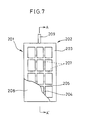
The single figure is a partially cutaway elevation illustrating yet another embodiment of a membrane cartridge according to the present invention. - [Fig. 8]
The single figure is a transverse cross section illustrating aforesaid membrane cartridge. - [Fig. 9]
The single figure is an enlarged sectional view illustrating an essential part of aforesaid membrane cartridge. - [Fig. 10]
The single figure is a partially cutaway elevation illustrating still another embodiment of a membrane cartridge according to the present invention. - [Fig. 11]
The single figure is a vertical section illustrating aforesaid membrane cartridge. - [Fig. 12]
The single figure is a transverse section illustrating aforesaid membrane cartridge. - [Fig. 13]
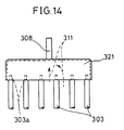
The single figure is an enlarged sectional view illustrating an essential part of aforesaid membrane cartridge. - [Fig. 14]
The single figure is an enlarged view illustrating an essential part of another membrane cartridge. - [Fig. 15]
The single figure is an enlarged sectional view illustrating an essential part of aforesaid membrane cartridge. - [Fig. 16]
The single figure is a partially cutaway elevation illustrating yet another embodiment of a membrane cartridge according to the present invention. - [Fig. 17]
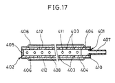
The single figure is a transverse section illustrating aforesaid membrane cartridge. - [Fig. 18]
The single figure is a vertical section illustrating aforesaid membrane cartridge. - [Fig. 19]
The single figure is a vertical section illustrating another membrane cartridge. - [Fig. 20]
The single figure is an enlarged view illustrating an essential part of another membrane cartridge. - [Fig. 21]
The single view is a partially cutaway elevation illustrating yet another embodiment of a membrane cartridge according to the present invention. - [Fig. 22]
The single figure is a vertical section illustrating aforesaid membrane cartridge. - [Fig. 23]
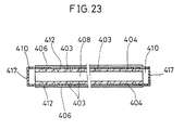
The single figure is a transverse section illustrating aforesaid membrane cartridge. - [Fig. 24]
The single figure is a perspective view illustrating the whole body of still another embodiment of a filtration membrane module according to the present invention. - [Fig. 25]
The single figure is a schematic sectional view illustrating an essential part of aforesaid filtration membrane module. - [Fig. 26]
The single figure is a partially cutaway view illustrating a membrane cartridge of aforesaid embodiment. - [Fig. 27]
The single figure is a vertical section illustrating aforesaid membrane cartridge. - [Fig. 28]
The single figure is a transverse section illustrating aforesaid membrane cartridge. - [Fig. 29]
The single figure is a partially cutaway view illustrating a membrane cartridge of still another embodiment according to the present invention. - [Fig. 30]
The single figure is a vertical section illustrating aforesaid membrane cartridge. - [Fig. 31]
The single figure is a transverse section illustrating aforesaid membrane cartridge. - An embodiment of the present invention will be described with reference to the attached drawings. Fig. 3 shows the whole structure of a filtration membrane module embodying the present invention.
- An
aeration tank 101 has afiltration membrane module 102 submerged therein and is used for purification/treatment of araw liquid 105 fed from a rawliquid feed pipe 104 while diffusing air and the like from adiffuser 103 disposed under thefiltration membrane module 102. Asludge suction pipe 107 with asludge pump 106 interposed thereon is connected to the bottom of theaeration tank 101 to drain excess sludge out of the tank. - The
filtration membrane module 102 is used for solid-liquid separation of mixed liquid in the aeration tank produced from the activated sludge process of theraw liquid 105. Thefiltration membrane module 102 comprises a box frame 109 having the top and bottom ends thereof open, andplural membrane cartridges 110 accommodated in the box frame as vertically placed in parallel to each other at given space intervals. - The
diffuser 103 is used for blowing anaeration gas 111 containing oxygen such as air into passages between themembrane cartridges 110, and is disposed under themembrane cartridges 110 being connected to ablower 113 via anair supply pipe 112. The passages of permeated liquid of themembrane cartridges 110 are communicated with a permeatedliquid tank 115 via asuction pipe 114. A suckingpump 117 for sucking the permeatedliquid 116 is interposed midway of thesuction pipe 114. - As shown in Figs. 4 and 5, the membrane cartridge comprises a
membrane supporting plate 118, membrane supporting net 119 andorganic filtration membrane 120. Themembrane supporting plate 118 has a rectangular frame body made of groove-shaped stainless steel member, and a space in the frame body forms the passage of permeatedliquid 116.Bars transverse bar 121 includesplural holes 123 penetrating therethrough lengthwise, while thelateral bar 122 includesplural holes 123 penetrating therethrough widthwise. Theholes 123 also form the passage of permeatedliquid 116. The membrane supporting net 119 between themembrane supporting plate 118 andfiltration membrane 120 is welded to the frame-shapedmembrane supporting plate 118. The membrane supporting net 119 supports thefiltration membrane 120 and also defines a predetermined gap between themembrane supporting plate 118 and thefiltration membrane 120. - The
filtration membrane 120 covers both surfaces of themembrane supporting plate 118 having its periphery adhered to themembrane supporting plate 118 with an adhesive or welded by heat or ultrasonic wave to the membrane supporting net 119 using a fusion tape, so that a gap between the membrane supporting plate and filtration membrane is kept water sealed. Themembrane supporting plate 118 comprises asuction nozzle 124, which introduces the permeatedliquid 116 to the outside of themembrane cartridge 110 as communicated with the inside of thefiltration membranes 120 and which is connected to saidsuction pipe 114. - In said arrangement, the
raw liquid 105 fed to theaeration tank 101 from the rawliquid feed pipe 104 is subject to an activated sludge process as aerated with theaeration gas 111 which is sent by theblower 113 through theair supply pipe 112 anddiffuser 103, and which is blown into the passages of themembrane cartridges 110. Themembrane cartridges 110 separate the mixed liquid in theaeration tank 108 into solid matter and liquid through thefiltration membrane 120, as the suckingpump 117 applies the sucking pressure through thesuction pipe 114 to the inside of the frame-likemembrane supporting plate 118. The purified permeated liquid through thefiltration membrane 120 is supplied through thesuction nozzle 124 andsuction pipe 114 to the permeatedliquid tank 115. Theaeration gas 111 spurted from thediffuser 103 generates an upward flow due to an air lift effect. The upward flow composes a gas-liquid cross current, flowing through the passages between the adjoiningmembrane cartridges 110 to serve as a cleaning stream in parallel to the membrane surfaces of thefiltration membranes 120, thereby restraining adhesion of the cake layer. - The
membrane supporting plate 118 has a hollow structure, which forms the broad passage of permeated liquid with low flow resistance. The permeatedliquid 116 through thefiltration membrane 120 slowly flows through the passage of permeated liquid, allowing the sucking pressure from the suckingpump 117 to be evenly applied to the whole surface of thefiltration membrane 120 of themembrane cartridges 110. Thus, the localization of the fouling is avoided on thefiltration membrane 120. - Due to a rigid frame structure, the passages defined between the
membrane cartridges 110 opposite to each other maintain a constant flow width at all times, so that the cleaning stream flows evenly over the whole surface of themembrane cartridges 110, producing the utmost cleaning effect. - The
filtration membrane 120 urged by the sucking pressure toward themembrane supporting plate 118 is retained by themembrane supporting plate 118 through the membrane supporting net 119, which maintains a constant gap between themembrane supporting plate 118 andfiltration membrane 120. The gap between thefiltration membrane 120 andmembrane supporting plate 118 forms a space across thefiltration membrane 120 as communicated with thesuction nozzle 124, allowing the sucking pressure to be applied to the whole surface of thefiltration membrane 120. As a result, the localization of the fouling on thefiltration membrane 120 is not only avoided but also permeate flux and the filtration length is increased. Furthermore, even the proliferation of microorganisms may not cause the closure of filtrate passages. - Instead of stainless steel, plastics may be used as materials for the frame body such as membrane supporting plate and membrane supporting net. Fig. 6 shows such an embodiment, in which elements having the same function as the previous embodiment are denoted by the same reference numerals.
- In this embodiment, a
membrane supporting plate 131 of themembrane cartridge 110 comprises crisscrossingbars bars - Figs. 7 and 8 shows another embodiment of the membrane cartridge in the filtration membrane module according to the present invention. According to Figs. 7 and 8, a
membrane cartridge 201 comprises a membrane supporting plate as a framing body which includes twoseparate frame bodies frame bodies frame portion 203 having a width of 5 to 15 mm, andlongitudinal bars 204 andtransverse bars 205 crisscrossed inside of theframe portion 203 and integrally formed therewith. - The
longitudinal bars 204 in aframe body 202 and those 204 in theother frame body 202, as well as thetransverse bars 205 in aframe body 202 and those 205 in theother frame body 202 are offset each other so that they will not oppose each other when the twoframe bodies 202 are coupled with each other, thereby preventing production of resistance to apassage 206 of permeated liquid formed between theframe bodies 202. Plural through-holes 207 are provided longitudinally in thetransverse bars 205 and transversely in thelongitudinal bars 204, composing a part of thepassage 206 of permeated liquid. A preferable pitch of thelongitudinal bars 204 andtransverse bars 205 is from 10 to 50 mm, and a proper width of thelongitudinal bars 204 andtransverse bars 205 is from 2 to 6 mm. As for the passage, it is preferable to provide through-holes 207 having a diameter of 1 to 2 mm at a pitch of 50 to 100 mm. - The
longitudinal bars 204 andtransverse bars 205 are flush with the surface of theframe portion 203 at one side of theframe body 202, the surface on which afiltration membrane 208 is disposed. A counterpart of acylindrical suction nozzle 209 for introducing the permeated liquid out of amembrane cartridge 201 is integrally formed with theframe portion 203. - On the surfaces of the
frame bodies protrusions 210 are provided on said opposite surface of one of saidframe bodies 202, whilerecesses 211 are provided on said opposite surface of theother frame body 202. By fitting theprotrusions 210 with therecesses 211, the twoframe bodies 202 are unified by joining theframe portions 203 and the counterparts of thesuction nozzle 209, thus composing a membrane supporting plate of themembrane cartridge 201. - To produce the
membrane cartridge 201, a thermal plastic resin such as ABS resin and the like which is molten at high temperatures is poured into a mold, thereby formingaforesaid frame body 202 comprising theframe portion 203, counterpart of thesuction nozzle 209,longitudinal bars 204 andtransverse bars 205, as well as either theprotrusions 210 or recesses 211. In this production process, thefiltration membrane 208 is set on one surface of theframe body 202 and is fused with the resin in order to form theframe body 202 andfiltration membrane 208 integrally. - Since this arrangement is adapted such that a pair of the
frame bodies filtration membrane 208 thereon are fixed to each other by fitting theprotrusions 210 with therecesses 211, themembrane cartridge 201 is readily disassembled or assembled, facilitating the cleaning of the filtration membrane in maintenance works. When the sucking pressure is applied, the permeated liquid can be drawn out through the passage of the through-holes while thefiltration membrane 208 being supported by thetransverse bars 204 andlongitudinal bars 205. Accordingly, the flow resistance of the permeated liquid is reduced. - Fig. 9 shows another example of a structure for joining the
frame bodies frame body 202 has aframe portion 221 whose opposing surface has an L-shape in section. The L-shaped part of theframe portion 221 is fit with the inner side of theframe portion 203 of theother frame body 202, and theprotrusion 210 andrecess 211 on the respective overlappingsurfaces frame bodies - Figs. 10 through 13 show another embodiment of the membrane cartridge in the filtration membrane module according to the present invention. According to Figs. 10 to 13, a
membrane supporting plate 302 of amembrane cartridge 301 comprises plural membrane supportingframe members 303 arranged in parallel to each other, and acoupling frame member 304 for coupling with an end of each of the membrane supportingframe members 303 as disposed in the direction to intersect with these membrane supportingframe members 303. The membrane supportingframe members 303 andcoupling frame member 304 are made of a rigid member such as plastics or stainless steel, and have a sectional form including circle, ellipse and square. - The other ends of the membrane supporting
frame members 303 are inserted in anopening 306 of aliquid collecting cap 305, and the membrane supportingframe members 303 andliquid collecting cap 305 are fixed to each other by means of fusion or adhesion. Thus,passage 307 of permeated liquid to theliquid collecting cap 305 are formed between the membrane supportingframe members liquid collecting cap 305 has asuction nozzle 308 communicated with asuction pipe 114. Thefiltration membrane 309, which is either microfiltration membrane or ultrafiltration membrane, is shaped like a bag, covering the both surfaces of themembrane supporting plate 302. It is fixed to the periphery of theliquid collecting cap 305 by means of adhesion or fusion for water sealing. Between themembrane supporting plate 302 andfiltration membrane 309, aporous member 310 encloses the membrane supportingframe members 303 of themembrane supporting plate 302 to protect thefiltration membrane 309. Theporous member 310 is made of a material such as felt, unwoven fabric or wool cloth which has fine communication apertures in the three-dimensional directions. - In this arrangement, by applying the sucking pressure through the
liquid collecting cap 305 to the passage of permeated liquid 307 between the membrane supportingframe members filtration membrane 309. After flowing through the passage of permeated liquid 307 between the membrane supportingframe members liquid 311 is introduced into thesuction pipe 114 through this broad passage in section, flowing without much flow resistance and so improving the filtration efficiency. - Since the
porous member 310 keeps the filtration membrane 309 a given distance away from themembrane supporting plate 302 at all times, the sucking pressure is readily applied to the whole surface of thefiltration membrane 309. This prevents the localization of the fouling on the membrane, further improving the filtration efficiency. - The
membrane supporting plate 302 is composed of the membrane supportingframe members 303 having rigidity, which is effective to avoid the uneven passage width between themembrane cartridges 301, thereby evenly distributing the cleaning stream to the whole surfaces of the membranes. This will restrain the local accumulation of deposit on the membrane surface, and therefore assure a long filtration length and high permeate flux. The membrane supportingframe members 303 andliquid collecting cap 305 may be formed integrally. - The
liquid collecting cap 305 andmembrane supporting plate 302 may also be joined in a manner shown in Figs. 14 and 15. According to Figs. 14 and 15, aliquid collecting cap 321 comprises anelastic step portion 322 along the inner peripheral side of the opening thereof. Thestep portions frame members 303. Theend portion 303a of the membrane supportingframe member 303 has a smaller diameter than the rest such that it may be inserted between thestep portions - This arrangement not only provides the same action as the previous embodiments, but also features a merit that because the membrane supporting
frame members 303 of themembrane supporting plate 302 are removably attached to theliquid collecting cap 309, themembrane supporting plate 302 is readily put to reuse after the disposal of theliquid collecting cap 321 when the life of thefiltration membrane 309 is expired. - Figs. 16 to 18 show another embodiment of the membrane cartridge in the filtration membrane module according to the present invention. In Figs. 16 to 18, a
membrane supporting plate 402 of amembrane cartridge 401 is made hollow, and comprises a pair offlat plates small apertures 1 to 3 mm in diameter and a plate-likecoupling support member 405 for joining the peripheries of said flat plates to close the same completely. Themembrane supporting plate 402 comprises afiltration membrane 406 covering the both surfaces thereof and asuction nozzle 407 for drawing out permeated liquid as communicated with the hollow part of themembrane supporting plate 402. - The
membrane supporting plate 402 includes thereinplural rib members 408 disposed in parallel to each other, which retain theflat plates form passage 409 of permeatedliquid therebetween suction nozzle 407 side, therib members 408 are spaced some distance from thecoupling support member 405 to define aliquid collecting portion 410 at the suction nozzle side. - Said
small apertures 403 are provided along thepassage 409 of permeated liquid between therib members 408. Therib members 408 may also includesmall apertures 411 for the permeated liquid to flow into theadjoining passage 409 of permeated liquid. - The
filtration membrane 406 for microfiltration or ultrafiltration has its periphery fixed to themembrane supporting plate 402 by means of adhesion or fusion. Aspacer 412 is interposed between themembrane supporting plate 402 andfiltration membrane 406, keeping themembrane supporting plate 402 some distance away from thefiltration membrane 406. Thespacer 412 is made of a material such as felt, unwoven fabric or wool cloth which has fine communication apertures in the three-dimensional directions. - In this arrangement, after entering the
membrane supporting plate 402 through thespacer 412 andsmall apertures 403 in theflat plate 404, the permeated liquid is introduced through thepassage 409 of permeated liquid to theliquid collecting portion 410, to be discharged out of themembrane cartridge 401 through thesuction nozzle 407. Since thepassage 409 of permeated liquid in themembrane supporting plate 402 has a large sectional area and besides, thesmall apertures 411 provide passages communicating the adjoiningpassages 409 of permeated liquid, the flow resistance in thepassages 409 of permeated liquid is kept low and the sucking pressure may be evenly applied to the whole surface of thefiltration membrane 406. - The hollow
membrane supporting plate 402 is supported by therib members 408 from inside, and thus deformation in the directions of X- and Y-axes is prevented. Accordingly, the width of the passage between themembrane cartridges 401 is kept constant so that the cleaning effect is equally distributed on the whole surface of thefiltration membrane 406. Thespacer 412 forms passages introducing permeated liquid in thesmall apertures 403. - As shown in Fig. 19, the
membrane cartridge 401 may also compriseslant rib members 413 between therib members slant rib member 413 connects the upper end of arib member 408 to the lower end of the adjoiningrib member 408. Theslant rib members 413 also includesmall apertures 414 for the permeated liquid to pass through. The arrangement of this embodiment produces the same action as the previous embodiments, and also further increases the rigidity of themembrane cartridge 401. - As shown in Fig. 20, the
flat plate 404 of themembrane cartridge 401 may also comprisethin slits 415 widthwise of thepassage 409 of permeated liquid, andthin grooves 416 communicated to thethin slits 415 may be laid over the surface of theflat plate 404. The arrangement of this embodiment produces the same action as the previous embodiments, and also facilitates the flow of permeated liquid into themembrane supporting plate 402 because thethin grooves 416 smoothly introduce the permeated liquid on the surface of theflat plate 404 to thethin slits 415. - As shown in Figs. 21 to 23, the
membrane cartridge 401 may comprise a pair offlat plates 404. The flat plate has its opposite sides coupled to the corresponding sides of the other flat plate, while the other two sides thereof form theliquid collecting portions 410 respectively. Specifically, a pair of rectangularflat plates longer sides 404a thereof by means of thecoupling support members 405, so as to form the hollow-shapedmembrane supporting plate 402. Groove-shaped liquid collecting caps 417 are provided at theshorter sides 404b of theflat plates 404 to form liquid collectingportions 410 inside of the liquid collecting caps 417. An end of theliquid collecting cap 417 is closed with acap 418, while thesuction nozzle 419 is attached to the other end of theliquid collecting cap 417. - The arrangement of this embodiment produces the same action as the previous embodiments. Furthermore, by applying the sucking pressure to the collecting
portions 410 at both end sides, the sucking pressure can be evenly applied to the whole surface of thefiltration membrane 405 even in a large membrane cartridge. - Another embodiment of the filtration membrane module according to the present invention is shown in Figs. 24 to 28. According to Figs. 24 to 28, a
filtration membrane module 500 comprises abox frame 501 with the top and bottom thereof made open; plate-like membrane cartridges 502 properly spaced in parallel to each other in thebox frame 501; andsuction nozzles 503 attached to themembrane cartridges 502 respectively. - The
box frame 501 accommodates adiffuser 504 under themembrane cartridges 502 and above the lower opening of thebox frame 501. Diffusingports 504a are provided at the lower part of thediffuser 504. - A
membrane supporting plate 505 of themembrane cartridge 502 is made of plastics or stainless steel molded into corrugated sheet, and has apassage 506 of permeated liquid on the surface thereof as well as afiltration membrane 507 covering the surface thereof. Aspacer 508 made of felt and the like which has communication apertures in the three-dimensional directions is interposed between themembrane supporting plate 505 andfiltration membrane 507. As shown in the figure, thefiltration membrane 507 may have a cylindrical form by having the opposite sides thereof adhered to each other. - A prismatic
edge support member 509 is disposed at an end of themembrane cartridge 502, concealing anend portion 505a of themembrane supporting plate 505 together with the edge of thefiltration membrane 507. Theedge support member 509 is slightly wider than themembrane supporting plate 505 and has a predetermined thickness, such that themembrane supporting plate 505 is sealed on its periphery by filling aresin 510 between thefiltration membrane 507 andedge support member 509. Theedge support member 509 includes therein a space as theliquid collecting portion 511 communicated with both thepassage 506 of permeated liquid andsuction nozzle 503. Theother end portion 505b of themembrane supporting plate 505 together with the edge of thefiltration membrane 507 are concealed by a solid-coreedge support member 512 having a predetermined thickness and a resin 513. - Utilizing the thickness of the
edge support member 509 and solid-coreedge support member 512, themembrane cartridges 502 are properly spaced in thebox frame 501. - In this arrangement, the aeration gas from the diffusing
ports 504 on thediffuser 504 is first spurted downward before it goes up. Accordingly, even if thediffuser 504 is close to the lower end of themembrane cartridges 502, the aeration gas will not swirl but goes up, flowing into the gaps between themembrane cartridges 502 fast enough to prevent the adhesion of sludge to the membrane surfaces. - Since the
membrane cartridge 502 has rigidity and is spaced a given distance from the adjoiningmembrane cartridges 502 by the thickness of theedge support member 509 thereof, the passage width is maintained constant even in a simple arrangement. This allows to take full advantage of the cleaning effect of the gas-liquid cross flow so that a normal volume of the aeration can prevent reduction of filtration length. - Alternatively, the
membrane cartridge 502 may be arranged as shown in Figs. 29 through 31. Themembrane supporting plate 521 of themembrane cartridge 502 comprises a pair ofside walls plural supporting walls 523 bridging the side walls in parallel. This arrangement imparts rigidity to themembrane supporting plate 521 and also defines thepassage 506 of permeated liquid in themembrane supporting plate 521. Pluralsmall apertures 524 having a diameter of 1 to 3 mm are provided on the surface of theside walls 522. Themembrane supporting plate 521 is covered with thefiltration membrane 507. Although this membrane cartridge has no spacer interposed, the spacer may be interposed between themembrane supporting plate 521 andfiltration membrane 507 to avoid close contact therebetween.
Claims (9)
- A filtration membrane module submerged with a processed liquid in a processing tank comprising:
a plurality of plate-like, rigid membrane cartridges vertically placed in parallel to each other as properly spaced from the adjoining membrane cartridges;
cleaning stream generating means for supplying a flow parallel to the membrane surfaces of the membrane cartridges which opposes to gaps defined between the membrane cartridges opposite to each other;
sucking means for sucking permeated liquid in each membrane cartridge which is communicated with the passage of permeated liquid in each membrane cartridge; and
a membrane supporting plate for retaining a filtration membrane of the membrane cartridge which is made hollow using a rigid structure member. - A filtration membrane module set forth in Claim 1, wherein
the membrane supporting plate is composed of a rigid frame structure;
the filtration membrane covers opening on the surface of the membrane supporting plate; and
a filtration membrane net is interposed between the membrane supporting plate and filtration membrane. - A filtration membrane set forth in Claim 1, wherein the membrane supporting plate composing the frame structure is divided into two frame bodies made of molded resin;
protrusions are provided on one of the opposite surfaces where the two frame bodies face to each other, while recesses are provided on the other opposite surface of the other frame body;
the filtration membrane covers the outer surface of each frame body thereby integrally forming the filtration membrane and frame body; and
the frame bodies are fixed to each other by fitting the protrusions with the recesses. - A filtration membrane module set forth in Claim 3, wherein
the frame body of the membrane supporting plate comprises bars for retaining the filtration membrane; and
the bars include holes to form the passage of permeated liquid. - A filtration membrane module set forth in Claim 1, wherein
the membrane cartridge includes a bag-shaped filtration membrane covering the outer surface of the membrane supporting plate; and
the membrane supporting plate comprises plural bar-shaped, rigid membrane supporting frame members disposed in parallel to each other,
a coupling frame member disposed as crossed with ends of the membrane supporting frame members to fix the same in one piece,
passages of permeated liquid defined in gaps between the respective membrane supporting frame members, and
a liquid collecting cap communicated with liquid collecting means and coupled to the other end of each membrane supporting frame member. - A filtration membrane module set forth in Claim 5, wherein the liquid collecting cap is detachably coupled with the other end of each membrane supporting frame member.
- A filtration membrane module set forth in Claim 1, wherein the membrane cartridge comprises:
a pair of plate members with fine apertures or slits disposed therein being coupled to each other on the peripheries thereof so as to form a hollow membrane supporting plate;
plural plate-like rib members having a width bridging the two plate members, which are disposed in parallel to each other in the membrane supporting plate; and
the passages of permeated liquid formed between the respective rib members. - A filtration membrane module set forth in Claim 7, wherein
a spacer interposed between the plate members of a membrane supporting plate and the filtration membrane to form a predetermined gap therebetween; and
fine grooves communicated with fine apertures or slits formed in the surfaces of the plate members. - A filtration membrane module set forth in any of Claims 1 through 8, wherein
a diffuser as the cleaning stream generating means is disposed under the membrane cartridges;
diffusing ports are disposed at the lower side of the diffuser;
edge supporting members disposed at opposite end portions of the membrane supporting plate and forming a predetermined gap between the filtration membranes of adjoining membrane cartridges which oppose to each other;
at least one of said edge supporting members is made hollow forming the passage of permeated liquid.
Applications Claiming Priority (6)
| Application Number | Priority Date | Filing Date | Title |
|---|---|---|---|
| JP00035394A JP3219579B2 (en) | 1994-01-07 | 1994-01-07 | Membrane module |
| JP352/94 | 1994-01-07 | ||
| JP353/94 | 1994-01-07 | ||
| JP00035294A JP3418443B2 (en) | 1994-01-07 | 1994-01-07 | Membrane module |
| JP7367394A JPH07275669A (en) | 1994-04-13 | 1994-04-13 | Membrane separator |
| JP73673/94 | 1994-04-13 |
Publications (2)
| Publication Number | Publication Date |
|---|---|
| EP0662341A1 true EP0662341A1 (en) | 1995-07-12 |
| EP0662341B1 EP0662341B1 (en) | 1998-03-04 |
Family
ID=27274433
Family Applications (1)
| Application Number | Title | Priority Date | Filing Date |
|---|---|---|---|
| EP94202825A Expired - Lifetime EP0662341B1 (en) | 1994-01-07 | 1994-09-30 | Filtration membrane module |
Country Status (10)
| Country | Link |
|---|---|
| US (1) | US5482625A (en) |
| EP (1) | EP0662341B1 (en) |
| CN (1) | CN1063983C (en) |
| AU (1) | AU668318B2 (en) |
| CA (1) | CA2132234C (en) |
| DE (1) | DE69408816T2 (en) |
| DK (1) | DK0662341T3 (en) |
| ES (1) | ES2115865T3 (en) |
| NZ (1) | NZ264488A (en) |
| TW (1) | TW255835B (en) |
Cited By (49)
| Publication number | Priority date | Publication date | Assignee | Title |
|---|---|---|---|---|
| EP0803274A1 (en) * | 1996-04-26 | 1997-10-29 | WABAG Wassertechnische Anlagen GmbH | Process and apparatus for treatment of backwash water from a filter |
| EP0937494A2 (en) * | 1998-02-23 | 1999-08-25 | Kubota Corporation | Membrane separation system |
| WO2001000307A2 (en) * | 1999-06-25 | 2001-01-04 | Millenniumpore Limited | Self cleaning filter |
| WO2002045827A1 (en) * | 2000-12-04 | 2002-06-13 | Kubota Corporation | Multistage immersion type membrane separator and high-concentration wastewater treatment facility using same |
| WO2002074424A1 (en) * | 2001-03-21 | 2002-09-26 | Itt Manufacturing Enterprises, Inc. | Apparatus for filtering a liquid |
| WO2003037489A1 (en) * | 2001-10-24 | 2003-05-08 | A3 Abfall-Abwasser-Anlagentechnik Gmbh | Plate filtration module |
| EP1366804A1 (en) * | 1998-04-21 | 2003-12-03 | Kubota Corporation | Method of replacement of a filtration membrane of a filtration cartridge for activated sludge |
| EP1433511A1 (en) * | 2002-12-19 | 2004-06-30 | Utisol Technologies AG | Filter device |
| WO2004082812A1 (en) * | 2003-03-13 | 2004-09-30 | 3M Innovative Properties Company | Liquid-liquid extraction system and method |
| GB2400845A (en) * | 2003-04-25 | 2004-10-27 | Aquator Group Ltd | Sewage and/or liquid waste treatment using membrane filters o n hangers |
| EP1475142A1 (en) * | 2003-05-09 | 2004-11-10 | Utisol Technologies AG | Membrane plate and filter comprising the same |
| WO2005060425A2 (en) * | 2003-12-03 | 2005-07-07 | 3M Innovative Properties Company | Membrane modules and integrated membrane cassettes |
| EP1567249A1 (en) * | 2002-12-05 | 2005-08-31 | U.S. Filter Wastewater Group, Inc. | Mixing chamber |
| EP1629881A1 (en) * | 2004-07-29 | 2006-03-01 | Baumann, Markus | Sewage treatment plant with membrane filtration |
| EP1676817A1 (en) * | 2004-12-17 | 2006-07-05 | McGuinness, Patrick | Submergible membrane filtration module |
| US7122709B2 (en) | 2003-03-13 | 2006-10-17 | 3M Innovative Properties Company | Method for obtaining ethanol |
| US7186343B2 (en) | 1998-10-09 | 2007-03-06 | Zenon Technology Partnership | Cyclic aeration system for submerged membrane modules |
| EP1814648A1 (en) * | 2004-11-26 | 2007-08-08 | A3 Water Solutions GmbH | Frameless, plate-shaped filtering member |
| DE102008040373A1 (en) * | 2008-07-11 | 2010-01-14 | Helmut Prieske | Membrane bioreactor and process for treating wastewater |
| EP2283988A1 (en) * | 2009-08-14 | 2011-02-16 | Nederlandse Organisatie voor toegepast -natuurwetenschappelijk onderzoek TNO | Planar membrane module preparation |
| WO2011019278A1 (en) * | 2009-08-14 | 2011-02-17 | Nederlandse Organisatie Voor Toegepast- Natuurwetenschappelijk Onderzoek Tno | Planar membrane module preparation |
| AU2006217128B2 (en) * | 2005-02-28 | 2011-08-11 | Alfa Laval Corporate Ab | Permeate spacer module |
| WO2013113928A1 (en) * | 2012-02-03 | 2013-08-08 | Vito Nv (Vlaamse Instelling Voor Technologisch Onderzoek Nv) | Backwashable filtration element |
| US8840783B2 (en) | 2007-05-29 | 2014-09-23 | Evoqua Water Technologies Llc | Water treatment membrane cleaning with pulsed airlift pump |
| US8858796B2 (en) | 2005-08-22 | 2014-10-14 | Evoqua Water Technologies Llc | Assembly for water filtration using a tube manifold to minimise backwash |
| US8956464B2 (en) | 2009-06-11 | 2015-02-17 | Evoqua Water Technologies Llc | Method of cleaning membranes |
| US9022224B2 (en) | 2010-09-24 | 2015-05-05 | Evoqua Water Technologies Llc | Fluid control manifold for membrane filtration system |
| US9023206B2 (en) | 2008-07-24 | 2015-05-05 | Evoqua Water Technologies Llc | Frame system for membrane filtration modules |
| WO2015114141A1 (en) * | 2014-02-03 | 2015-08-06 | Sani Membranes Aps | Filter plate assembly |
| WO2015114140A1 (en) * | 2014-02-03 | 2015-08-06 | Sani Membranes Aps | Filter plate assembly |
| WO2015140355A1 (en) | 2014-03-21 | 2015-09-24 | Vito Nv (Vlaamse Instelling Voor Technologisch Onderzoek Nv) | Supported filtration membranes and methods of manufacturing |
| CN105327532A (en) * | 2014-08-13 | 2016-02-17 | 曹志明 | Superhigh pressure chamber-type filter press |
| WO2016087638A1 (en) | 2014-12-05 | 2016-06-09 | Vito Nv (Vlaamse Instelling Voor Technologisch Onderzoek Nv) | Membrane cartridge with integrated functions |
| US9533261B2 (en) | 2012-06-28 | 2017-01-03 | Evoqua Water Technologies Llc | Potting method |
| US9604166B2 (en) | 2011-09-30 | 2017-03-28 | Evoqua Water Technologies Llc | Manifold arrangement |
| US9675938B2 (en) | 2005-04-29 | 2017-06-13 | Evoqua Water Technologies Llc | Chemical clean for membrane filter |
| US9764288B2 (en) | 2007-04-04 | 2017-09-19 | Evoqua Water Technologies Llc | Membrane module protection |
| US9764289B2 (en) | 2012-09-26 | 2017-09-19 | Evoqua Water Technologies Llc | Membrane securement device |
| US9815027B2 (en) | 2012-09-27 | 2017-11-14 | Evoqua Water Technologies Llc | Gas scouring apparatus for immersed membranes |
| WO2017211738A1 (en) | 2016-06-08 | 2017-12-14 | Vito Nv (Vlaamse Instelling Voor Technologisch Onderzoek Nv) | Membrane support made with preformed sheets |
| WO2017211750A1 (en) * | 2016-06-08 | 2017-12-14 | Vito Nv (Vlaamse Instelling Voor Technologisch Onderzoek Nv) | Biomass membrane contactor |
| US9914097B2 (en) | 2010-04-30 | 2018-03-13 | Evoqua Water Technologies Llc | Fluid flow distribution device |
| US9925499B2 (en) | 2011-09-30 | 2018-03-27 | Evoqua Water Technologies Llc | Isolation valve with seal for end cap of a filtration system |
| US9962865B2 (en) | 2012-09-26 | 2018-05-08 | Evoqua Water Technologies Llc | Membrane potting methods |
| EP3316995A4 (en) * | 2015-06-30 | 2019-03-06 | EMD Millipore Corporation | Sealing case for filter cassette |
| US10427102B2 (en) | 2013-10-02 | 2019-10-01 | Evoqua Water Technologies Llc | Method and device for repairing a membrane filtration module |
| EP4159302A1 (en) | 2021-09-30 | 2023-04-05 | Vito NV | Composite filter membranes providing increased flowability |
| WO2023073171A1 (en) * | 2021-10-29 | 2023-05-04 | Blue Foot Membranes Nv | Filtration membrane module |
| US11813576B2 (en) | 2018-03-08 | 2023-11-14 | Sani Membranes Aps | Filter-plate assembly with external flow areas and attached membranes |
Families Citing this family (111)
| Publication number | Priority date | Publication date | Assignee | Title |
|---|---|---|---|---|
| US20020134740A1 (en) * | 2001-03-23 | 2002-09-26 | Pierre Cote | Inverted air box aerator and aeration method for immersed membrane |
| US6863823B2 (en) * | 2001-03-23 | 2005-03-08 | Zenon Environmental Inc. | Inverted air box aerator and aeration method for immersed membrane |
| US7087173B2 (en) * | 1995-08-11 | 2006-08-08 | Zenon Environmental Inc. | Inverted cavity aerator for membrane module |
| US5651889A (en) * | 1996-03-25 | 1997-07-29 | Mitsui Petrochemical Industries, Ltd. | Sludge treatment membrane apparatus |
| EP1736234A3 (en) * | 1996-12-20 | 2007-06-13 | Siemens Water Technologies Corp. | Method for scouring fouled membranes |
| TW422736B (en) * | 1998-04-24 | 2001-02-21 | Mitsui Zosen Engineering Kk | Method and apparatus for membrane treatment |
| US6550747B2 (en) | 1998-10-09 | 2003-04-22 | Zenon Environmental Inc. | Cyclic aeration system for submerged membrane modules |
| DE69924642T2 (en) * | 1998-11-23 | 2006-02-09 | Zenon Environmental Inc., Oakville | WATER FILTRATION BY UNDERWATER MEMBRANES |
| DE20016417U1 (en) * | 2000-09-21 | 2002-02-14 | Wehrle Werk Ag | Device for separating liquid and solid from a suspension |
| NL1016705C2 (en) * | 2000-11-24 | 2002-05-27 | Paques Water Systems B V | Device and method for cleaning a fluid, such as water. |
| US20050218074A1 (en) * | 2004-04-06 | 2005-10-06 | Pollock David C | Method and apparatus providing improved throughput and operating life of submerged membranes |
| AUPR421501A0 (en) | 2001-04-04 | 2001-05-03 | U.S. Filter Wastewater Group, Inc. | Potting method |
| AUPR692401A0 (en) | 2001-08-09 | 2001-08-30 | U.S. Filter Wastewater Group, Inc. | Method of cleaning membrane modules |
| EP1461140A1 (en) * | 2002-01-02 | 2004-09-29 | Triple I | Module with self-supporting sheet membranes |
| AUPS300602A0 (en) | 2002-06-18 | 2002-07-11 | U.S. Filter Wastewater Group, Inc. | Methods of minimising the effect of integrity loss in hollow fibre membrane modules |
| US8147699B2 (en) * | 2002-08-21 | 2012-04-03 | Hpd, Llc | Monolith filter apparatus and membrane apparatus, and method using same |
| US7938966B2 (en) * | 2002-10-10 | 2011-05-10 | Siemens Water Technologies Corp. | Backwash method |
| US7678284B2 (en) * | 2003-01-09 | 2010-03-16 | Grouse Mountain, Inc. | Tertiary filter |
| ATE395127T1 (en) * | 2003-03-05 | 2008-05-15 | Hydranautics | SUBMERSIBLE MEMBRANE MODULE WITH INTERCHANGEABLE MEMBRANE ELEMENTS |
| US6986428B2 (en) * | 2003-05-14 | 2006-01-17 | 3M Innovative Properties Company | Fluid separation membrane module |
| NZ545206A (en) | 2003-08-29 | 2009-03-31 | Siemens Water Tech Corp | Backwash |
| US20050115899A1 (en) * | 2003-10-21 | 2005-06-02 | Minggang Liu | Membrane bioreactor having single header membrane module |
| NZ546959A (en) | 2003-11-14 | 2008-03-28 | Siemens Water Tech Corp | Improved cleaning method for a porous membrane filtration module |
| EP1723084A2 (en) * | 2004-02-26 | 2006-11-22 | Hans Huber AG Maschinen- und Anlagenbau | Installation and method for the treatment of sewage sludge, and membrane unit |
| DE102004009886A1 (en) * | 2004-02-26 | 2005-09-15 | Hans Huber Ag Maschinen- Und Anlagenbau | Process and assembly to treat sewage sludge in an assembly that separates sludge and filtrate |
| WO2005092799A1 (en) | 2004-03-26 | 2005-10-06 | U.S. Filter Wastewater Group, Inc. | Process and apparatus for purifying impure water using microfiltration or ultrafiltration in combination with reverse osmosis |
| US7122121B1 (en) | 2004-05-28 | 2006-10-17 | Jiang Ji | Advanced submerged membrane modules, systems and processes |
| CA2579168C (en) | 2004-09-07 | 2015-06-23 | Siemens Water Technologies Corp. | Membrane filtration with reduced volume cleaning step |
| GB0420071D0 (en) * | 2004-09-10 | 2004-10-13 | Brightwater Engineering Ltd | Apparatus and method |
| CN101039739B (en) | 2004-09-14 | 2014-10-08 | 伊沃夸水处理技术有限责任公司 | Methods and apparatus for removing solids from a membrane module |
| WO2006029465A1 (en) | 2004-09-15 | 2006-03-23 | Siemens Water Technologies Corp. | Continuously variable aeration |
| US7297278B2 (en) * | 2004-10-20 | 2007-11-20 | Baker Hughes Incorporated | Methods for removing metals from water |
| SG150505A1 (en) | 2004-12-24 | 2009-03-30 | Siemens Water Tech Corp | Cleaning in membrane filtration systems |
| US8758622B2 (en) | 2004-12-24 | 2014-06-24 | Evoqua Water Technologies Llc | Simple gas scouring method and apparatus |
| KR20070097107A (en) * | 2005-01-14 | 2007-10-02 | 지멘스 워터 테크놀로지스 코포레이션 | Filtration system |
| US20060191837A1 (en) * | 2005-02-28 | 2006-08-31 | Alfa Laval Corporate Ab | Permeate spacer module |
| CN100518907C (en) * | 2005-03-09 | 2009-07-29 | 浙江欧美环境工程有限公司 | Floating suspenion hollow fiber porous film filter component element |
| JPWO2007122839A1 (en) * | 2006-03-27 | 2009-09-03 | 東レ株式会社 | Membrane element, membrane unit and multi-stage stacked membrane unit |
| US8293098B2 (en) | 2006-10-24 | 2012-10-23 | Siemens Industry, Inc. | Infiltration/inflow control for membrane bioreactor |
| CN101168113B (en) * | 2006-10-26 | 2010-12-22 | 康那香企业股份有限公司 | Solid-liquid separating type filter material for film biological processing and filter and filtering module |
| US8318028B2 (en) | 2007-04-02 | 2012-11-27 | Siemens Industry, Inc. | Infiltration/inflow control for membrane bioreactor |
| EP1992400A1 (en) * | 2007-05-18 | 2008-11-19 | Vlaamse Instelling Voor Technologisch Onderzoek (Vito) | Membrane bag and method of producing same |
| KR101497305B1 (en) * | 2007-07-03 | 2015-03-04 | 스미토모덴키고교가부시키가이샤 | Flat-membrane element for filtration and flat-membrane filtration module |
| KR101331675B1 (en) * | 2007-10-12 | 2013-11-26 | 코오롱인더스트리 주식회사 | System and Method for Installing Hollow Fiber Membrane Module to Frame Structure |
| KR100958785B1 (en) | 2007-10-30 | 2010-05-18 | 코오롱건설주식회사 | Hollow Fiber Membrane Module and Filtering Apparatus having The Same |
| WO2009118789A1 (en) * | 2008-03-27 | 2009-10-01 | 株式会社クボタ | Membrane element and membrane module |
| CN101980764B (en) * | 2008-03-27 | 2015-07-01 | 株式会社久保田 | Membrane element and membrane module |
| CA2734796A1 (en) | 2008-08-20 | 2010-02-25 | Siemens Water Technologies Corp. | Improved membrane system backwash energy efficiency |
| JP5566031B2 (en) * | 2009-01-06 | 2014-08-06 | 株式会社クボタ | Spacing member, membrane element, and submerged membrane separator |
| US8308939B2 (en) * | 2009-07-06 | 2012-11-13 | Ovivo Luxembourg S.a.r.l. | Efficient arrangement of membrane bioreactors |
| WO2011004743A1 (en) * | 2009-07-10 | 2011-01-13 | 住友電工ファインポリマー株式会社 | Flat membrane element for filtration, flat membrane type separation membrane module, and filtration device |
| WO2011025698A1 (en) * | 2009-08-28 | 2011-03-03 | Dow Global Technologies Llc | Filtration module including membrane sheet with capillary channels |
| DK2473259T3 (en) * | 2009-09-03 | 2014-05-19 | Vito | Filter membrane with support frame and method of manufacture |
| US20110100912A1 (en) * | 2009-11-03 | 2011-05-05 | Sanghoon Lee | Immersion type membrane separator device |
| KR101196794B1 (en) * | 2009-11-05 | 2012-11-05 | 주식회사 코레드 | Membrane Module And Membrane Module Assembly, And Immersion Type Membrane Separator Device Comprising Thereof |
| KR101810708B1 (en) * | 2010-03-23 | 2017-12-19 | 도레이 카부시키가이샤 | Separation membrane and method for producing same |
| US9492792B2 (en) | 2010-04-20 | 2016-11-15 | Fibracast Ltd. | Formed sheet membrane element and filtration system |
| CN103069246B (en) | 2010-06-24 | 2016-02-03 | 北狄空气应对加拿大公司 | Liquid-to-air membrane energy exchanger |
| US8114478B1 (en) | 2010-09-17 | 2012-02-14 | Dow Global Technologies Llc | Dual-sided membrane sheet and method for making the same |
| JP5608110B2 (en) * | 2011-01-18 | 2014-10-15 | 株式会社クボタ | Membrane separator |
| US8915092B2 (en) | 2011-01-19 | 2014-12-23 | Venmar Ces, Inc. | Heat pump system having a pre-processing module |
| CN103635683A (en) | 2011-06-30 | 2014-03-12 | 康宁股份有限公司 | Replaceable fuel separation unit |
| US9810439B2 (en) | 2011-09-02 | 2017-11-07 | Nortek Air Solutions Canada, Inc. | Energy exchange system for conditioning air in an enclosed structure |
| JP2013056298A (en) * | 2011-09-08 | 2013-03-28 | Fuji Electric Co Ltd | Filtering apparatus and method for operating the apparatus |
| KR102244592B1 (en) | 2011-10-20 | 2021-04-26 | 파이브라케스트 리미티드 | Coating device and process for coating formed sheet membrane element |
| US9132388B2 (en) | 2011-11-28 | 2015-09-15 | Corning Incorporated | Partition fluid separation |
| CA2798889A1 (en) * | 2011-12-16 | 2013-06-16 | Meurer Research Inc. | Method and system for cleaning membrane filters |
| US8894048B2 (en) | 2012-07-17 | 2014-11-25 | Dow Global Technologies Llc | Gas diffuser |
| US20140054004A1 (en) * | 2012-08-24 | 2014-02-27 | Venmar Ces, Inc. | Membrane support assembly for an energy exchanger |
| US9816760B2 (en) | 2012-08-24 | 2017-11-14 | Nortek Air Solutions Canada, Inc. | Liquid panel assembly |
| CN103785296A (en) * | 2012-11-01 | 2014-05-14 | 河源海川科技有限公司 | Biomembrane unit and membrane bioreactor |
| US20150360157A1 (en) | 2013-02-18 | 2015-12-17 | Amogreentech Co., Ltd. | Filter medium, manufacturing method therefor, and filter equipment using same |
| US9109808B2 (en) | 2013-03-13 | 2015-08-18 | Venmar Ces, Inc. | Variable desiccant control energy exchange system and method |
| US9772124B2 (en) | 2013-03-13 | 2017-09-26 | Nortek Air Solutions Canada, Inc. | Heat pump defrosting system and method |
| US10352628B2 (en) | 2013-03-14 | 2019-07-16 | Nortek Air Solutions Canada, Inc. | Membrane-integrated energy exchange assembly |
| US11408681B2 (en) | 2013-03-15 | 2022-08-09 | Nortek Air Solations Canada, Iac. | Evaporative cooling system with liquid-to-air membrane energy exchanger |
| US10584884B2 (en) | 2013-03-15 | 2020-03-10 | Nortek Air Solutions Canada, Inc. | Control system and method for a liquid desiccant air delivery system |
| EP2905066A1 (en) * | 2014-02-10 | 2015-08-12 | Alfa Laval Corporate AB | Filtration module |
| DK3183051T3 (en) | 2014-08-19 | 2020-06-02 | Nortek Air Solutions Canada Inc | LIQUID-TO-LUFTMEMBRANENERGIVEKSLERE |
| WO2016149596A1 (en) | 2015-03-18 | 2016-09-22 | The Procter & Gamble Company | Absorbent article with waist gasketing element and leg cuffs |
| MX2017011926A (en) | 2015-03-18 | 2017-12-15 | Procter & Gamble | Absorbent article with leg cuffs. |
| EP3270846B1 (en) | 2015-03-18 | 2019-06-19 | The Procter and Gamble Company | Absorbent article with leg cuffs |
| WO2016149595A1 (en) | 2015-03-18 | 2016-09-22 | The Procter & Gamble Company | Absorbent article with waist gasketing element and leg cuffs |
| EP3270843A1 (en) | 2015-03-18 | 2018-01-24 | The Procter & Gamble Company | Absorbent article with waist gasketing element and leg cuffs |
| US10588790B2 (en) | 2015-03-18 | 2020-03-17 | The Procter & Gamble Company | Absorbent article with leg cuffs |
| BR112017019861A2 (en) | 2015-03-18 | 2018-05-29 | The Procter & Gamble Company | absorbent article with waist sealing element and leg clamps |
| US10716716B2 (en) | 2015-03-18 | 2020-07-21 | The Procter & Gamble Company | Absorbent article with leg cuffs |
| BR112017019872A2 (en) | 2015-03-18 | 2018-05-29 | The Procter & Gamble Company | absorbent article with leg cuffs |
| US10485710B2 (en) | 2015-03-18 | 2019-11-26 | The Procter & Gamble Company | Absorbent article with leg cuffs |
| SG10201913923WA (en) | 2015-05-15 | 2020-03-30 | Nortek Air Solutions Canada Inc | Using liquid to air membrane energy exchanger for liquid cooling |
| US11092349B2 (en) | 2015-05-15 | 2021-08-17 | Nortek Air Solutions Canada, Inc. | Systems and methods for providing cooling to a heat load |
| CA2990765A1 (en) | 2015-06-26 | 2016-12-29 | Nortek Air Solutions Canada, Inc. | Three-fluid liquid to air membrane energy exchanger |
| US10322375B2 (en) | 2015-07-14 | 2019-06-18 | Evoqua Water Technologies Llc | Aeration device for filtration system |
| EP3426984A4 (en) | 2016-03-08 | 2019-11-20 | Nortek Air Solutions Canada, Inc. | Systems and methods for providing cooling to a heat load |
| CN109311703B (en) * | 2016-05-31 | 2020-02-11 | 株式会社明电舍 | Membrane separation device, structure for arranging membrane elements, and membrane cartridge and membrane unit |
| KR101902637B1 (en) * | 2016-11-30 | 2018-09-28 | 두산중공업 주식회사 | Membrane filtration system |
| WO2018191806A1 (en) | 2017-04-18 | 2018-10-25 | Nortek Air Solutions Canada, Inc. | Desiccant enhanced evaporative cooling systems and methods |
| CN106984197A (en) * | 2017-05-27 | 2017-07-28 | 湖南科技大学 | A kind of submerged modular construction flat ceramic membrane filtration system |
| WO2018234956A1 (en) * | 2017-06-21 | 2018-12-27 | King Abdullah University Of Science And Technology | Compact high-throughput device for water treatment |
| CN109107248A (en) * | 2017-06-26 | 2019-01-01 | 上海斯纳普膜分离科技有限公司 | The method that solid particle in liquid is carried out separation and recycling using plain filter membrane |
| DE102017116156B4 (en) * | 2017-07-18 | 2019-06-27 | Kay Gunther Gabriel | filtration system |
| JP2021529087A (en) | 2018-07-03 | 2021-10-28 | フィブラキャスト リミティド | Closely spaced immersion flat membrane and fine cell aeration |
| US11760669B2 (en) * | 2018-08-09 | 2023-09-19 | Go Higher Environment Group Co., Ltd. | Flat membrane support plate |
| CN109020016B (en) * | 2018-09-20 | 2021-08-31 | 义乌市巨界机械设备有限公司 | Graded filtering sewage purification device |
| CN111482045A (en) * | 2020-04-03 | 2020-08-04 | 义乌鸿川科技有限公司 | Membrane skeleton for oxygen production compressor |
| CN111513384A (en) * | 2020-04-29 | 2020-08-11 | 王树芳 | Mask convenient for drinking water |
| CN111924869A (en) * | 2020-08-17 | 2020-11-13 | 中科铜都粉体新材料股份有限公司 | Silver nitrate lead-removing purification process |
| CN113526736A (en) * | 2021-08-02 | 2021-10-22 | 太和县大华能源科技有限公司 | Waste acid recovery device and recovery method of lead-acid storage battery |
| CN113667576B (en) * | 2021-09-01 | 2023-10-27 | 河北康欣跃达生物科技有限公司 | Thallus collection device |
| CN114558454B (en) * | 2022-01-14 | 2023-05-02 | 杭州科百特过滤器材有限公司 | Virus-removing filter |
| CN115611974B (en) * | 2022-10-24 | 2023-06-06 | 上海华新生物高技术有限公司 | Filter sterilization equipment for preparing interferon purified protein |
Citations (6)
| Publication number | Priority date | Publication date | Assignee | Title |
|---|---|---|---|---|
| JPH0259098A (en) * | 1988-08-24 | 1990-02-28 | Kubota Ltd | Activated sludge treatment apparatus |
| JPH0286893A (en) * | 1988-09-22 | 1990-03-27 | Kubota Ltd | Activated sludge treating device |
| JPH03188926A (en) * | 1989-12-19 | 1991-08-16 | Kubota Corp | Filtration treating method |
| EP0510328A2 (en) * | 1991-03-07 | 1992-10-28 | Kubota Corporation | Apparatus for treating activated sludge |
| JPH04334530A (en) * | 1991-05-10 | 1992-11-20 | Kubota Corp | Filter apparatus |
| EP0602560A1 (en) * | 1992-12-16 | 1994-06-22 | Kubota Corporation | Filtration membrane cartridge |
Family Cites Families (4)
| Publication number | Priority date | Publication date | Assignee | Title |
|---|---|---|---|---|
| US1724436A (en) * | 1924-01-24 | 1929-08-13 | Oliver United Filters Inc | Thickener |
| GB1278776A (en) * | 1968-07-05 | 1972-06-21 | William Boby & Company Ltd | A separator for a membrane pack |
| DE3726865A1 (en) * | 1986-08-12 | 1988-02-18 | Fuji Photo Film Co Ltd | FILTER CARTRIDGE |
| GB8620468D0 (en) * | 1986-08-22 | 1986-10-01 | Atomic Energy Authority Uk | Liquid treatment apparatus |
-
1994
- 1994-09-09 TW TW83108340A patent/TW255835B/en active
- 1994-09-16 CA CA002132234A patent/CA2132234C/en not_active Expired - Fee Related
- 1994-09-19 AU AU73064/94A patent/AU668318B2/en not_active Ceased
- 1994-09-20 NZ NZ264488A patent/NZ264488A/en unknown
- 1994-09-20 US US08/309,246 patent/US5482625A/en not_active Expired - Lifetime
- 1994-09-28 CN CN94116515A patent/CN1063983C/en not_active Expired - Fee Related
- 1994-09-30 EP EP94202825A patent/EP0662341B1/en not_active Expired - Lifetime
- 1994-09-30 ES ES94202825T patent/ES2115865T3/en not_active Expired - Lifetime
- 1994-09-30 DK DK94202825T patent/DK0662341T3/en active
- 1994-09-30 DE DE69408816T patent/DE69408816T2/en not_active Expired - Lifetime
Patent Citations (6)
| Publication number | Priority date | Publication date | Assignee | Title |
|---|---|---|---|---|
| JPH0259098A (en) * | 1988-08-24 | 1990-02-28 | Kubota Ltd | Activated sludge treatment apparatus |
| JPH0286893A (en) * | 1988-09-22 | 1990-03-27 | Kubota Ltd | Activated sludge treating device |
| JPH03188926A (en) * | 1989-12-19 | 1991-08-16 | Kubota Corp | Filtration treating method |
| EP0510328A2 (en) * | 1991-03-07 | 1992-10-28 | Kubota Corporation | Apparatus for treating activated sludge |
| JPH04334530A (en) * | 1991-05-10 | 1992-11-20 | Kubota Corp | Filter apparatus |
| EP0602560A1 (en) * | 1992-12-16 | 1994-06-22 | Kubota Corporation | Filtration membrane cartridge |
Non-Patent Citations (4)
| Title |
|---|
| DATABASE WPI Week 9015, Derwent World Patents Index; AN 90-110221 * |
| DATABASE WPI Week 9018, Derwent World Patents Index; AN 90-137162 * |
| DATABASE WPI Week 9139, Derwent World Patents Index; AN 91-285216 * |
| DATABASE WPI Week 9301, Derwent World Patents Index; AN 93-005613 * |
Cited By (88)
| Publication number | Priority date | Publication date | Assignee | Title |
|---|---|---|---|---|
| EP0803274A1 (en) * | 1996-04-26 | 1997-10-29 | WABAG Wassertechnische Anlagen GmbH | Process and apparatus for treatment of backwash water from a filter |
| EP0937494A2 (en) * | 1998-02-23 | 1999-08-25 | Kubota Corporation | Membrane separation system |
| EP0937494A3 (en) * | 1998-02-23 | 2000-03-01 | Kubota Corporation | Membrane separation system |
| EP1366804A1 (en) * | 1998-04-21 | 2003-12-03 | Kubota Corporation | Method of replacement of a filtration membrane of a filtration cartridge for activated sludge |
| US7186343B2 (en) | 1998-10-09 | 2007-03-06 | Zenon Technology Partnership | Cyclic aeration system for submerged membrane modules |
| WO2001000307A3 (en) * | 1999-06-25 | 2001-07-05 | Millenniumpore Ltd | Self cleaning filter |
| WO2001000307A2 (en) * | 1999-06-25 | 2001-01-04 | Millenniumpore Limited | Self cleaning filter |
| WO2002045827A1 (en) * | 2000-12-04 | 2002-06-13 | Kubota Corporation | Multistage immersion type membrane separator and high-concentration wastewater treatment facility using same |
| KR100768841B1 (en) * | 2000-12-04 | 2007-10-19 | 구보다코포레이션 | Multistage immersion type membrane separator and high-concentration wastewater treatment facility using same |
| AU781443B2 (en) * | 2000-12-04 | 2005-05-26 | Kubota Corporation | Multistage immersion type membrane separator and high-concentration wastewater treatment facility using same |
| US6843908B2 (en) | 2000-12-04 | 2005-01-18 | Kubota Corporation | Multistage immersion type membrane separator and high-concentration wastewater treatment facility using same |
| WO2002074424A1 (en) * | 2001-03-21 | 2002-09-26 | Itt Manufacturing Enterprises, Inc. | Apparatus for filtering a liquid |
| WO2003037489A1 (en) * | 2001-10-24 | 2003-05-08 | A3 Abfall-Abwasser-Anlagentechnik Gmbh | Plate filtration module |
| AU2003291835B2 (en) * | 2002-12-05 | 2010-06-17 | Evoqua Water Technologies Llc | Mixing chamber |
| EP1567249A4 (en) * | 2002-12-05 | 2006-01-11 | Us Filter Wastewater Group Inc | Mixing chamber |
| EP1567249A1 (en) * | 2002-12-05 | 2005-08-31 | U.S. Filter Wastewater Group, Inc. | Mixing chamber |
| EP1433511A1 (en) * | 2002-12-19 | 2004-06-30 | Utisol Technologies AG | Filter device |
| AU2010219360B2 (en) * | 2002-12-19 | 2011-07-07 | Utisol Technologies Ag | Filter device |
| WO2004056446A1 (en) * | 2002-12-19 | 2004-07-08 | Utisol Technologies Ag | Filter device |
| HRP20050566B1 (en) * | 2002-12-19 | 2008-06-30 | Utisol Technologies Ag | Filter device |
| WO2004082812A1 (en) * | 2003-03-13 | 2004-09-30 | 3M Innovative Properties Company | Liquid-liquid extraction system and method |
| US7517455B2 (en) | 2003-03-13 | 2009-04-14 | 3M Innovative Properties Company | Liquid-liquid extraction system and method |
| US7105089B2 (en) | 2003-03-13 | 2006-09-12 | 3M Innovative Properties Company | Liquid—liquid extraction system and method |
| US7122709B2 (en) | 2003-03-13 | 2006-10-17 | 3M Innovative Properties Company | Method for obtaining ethanol |
| EP2404663A1 (en) * | 2003-03-13 | 2012-01-11 | 3M Innovative Properties Co. | Liquid-liquid extraction method |
| GB2400845B (en) * | 2003-04-25 | 2006-06-07 | Aquator Group Ltd | Sewage and/or liquid waste treatment |
| GB2400845A (en) * | 2003-04-25 | 2004-10-27 | Aquator Group Ltd | Sewage and/or liquid waste treatment using membrane filters o n hangers |
| EP1475142A1 (en) * | 2003-05-09 | 2004-11-10 | Utisol Technologies AG | Membrane plate and filter comprising the same |
| WO2004098754A1 (en) * | 2003-05-09 | 2004-11-18 | Utisol Technologies Ag | Membrane plate and filter element |
| US7678273B2 (en) | 2003-05-09 | 2010-03-16 | Utisol Technologies Ag | Membrane plate and filter element |
| WO2005060425A2 (en) * | 2003-12-03 | 2005-07-07 | 3M Innovative Properties Company | Membrane modules and integrated membrane cassettes |
| WO2005060425A3 (en) * | 2003-12-03 | 2005-09-22 | 3M Innovative Properties Co | Membrane modules and integrated membrane cassettes |
| CN1890016B (en) * | 2003-12-03 | 2011-05-18 | 3M创新有限公司 | Membrane modules and integrated membrane cassettes |
| US7279215B2 (en) | 2003-12-03 | 2007-10-09 | 3M Innovative Properties Company | Membrane modules and integrated membrane cassettes |
| EP1629881A1 (en) * | 2004-07-29 | 2006-03-01 | Baumann, Markus | Sewage treatment plant with membrane filtration |
| EP1814648A1 (en) * | 2004-11-26 | 2007-08-08 | A3 Water Solutions GmbH | Frameless, plate-shaped filtering member |
| EP1676817A1 (en) * | 2004-12-17 | 2006-07-05 | McGuinness, Patrick | Submergible membrane filtration module |
| AU2006217128B2 (en) * | 2005-02-28 | 2011-08-11 | Alfa Laval Corporate Ab | Permeate spacer module |
| US9675938B2 (en) | 2005-04-29 | 2017-06-13 | Evoqua Water Technologies Llc | Chemical clean for membrane filter |
| US8894858B1 (en) | 2005-08-22 | 2014-11-25 | Evoqua Water Technologies Llc | Method and assembly for water filtration using a tube manifold to minimize backwash |
| US8858796B2 (en) | 2005-08-22 | 2014-10-14 | Evoqua Water Technologies Llc | Assembly for water filtration using a tube manifold to minimise backwash |
| US9764288B2 (en) | 2007-04-04 | 2017-09-19 | Evoqua Water Technologies Llc | Membrane module protection |
| US9206057B2 (en) | 2007-05-29 | 2015-12-08 | Evoqua Water Technologies Llc | Membrane cleaning with pulsed airlift pump |
| US9573824B2 (en) | 2007-05-29 | 2017-02-21 | Evoqua Water Technologies Llc | Membrane cleaning with pulsed airlift pump |
| US10507431B2 (en) | 2007-05-29 | 2019-12-17 | Evoqua Water Technologies Llc | Membrane cleaning with pulsed airlift pump |
| US8840783B2 (en) | 2007-05-29 | 2014-09-23 | Evoqua Water Technologies Llc | Water treatment membrane cleaning with pulsed airlift pump |
| DE102008040373A1 (en) * | 2008-07-11 | 2010-01-14 | Helmut Prieske | Membrane bioreactor and process for treating wastewater |
| US9023206B2 (en) | 2008-07-24 | 2015-05-05 | Evoqua Water Technologies Llc | Frame system for membrane filtration modules |
| US8956464B2 (en) | 2009-06-11 | 2015-02-17 | Evoqua Water Technologies Llc | Method of cleaning membranes |
| CN102548727B (en) * | 2009-08-14 | 2016-06-15 | 荷兰应用自然科学研究组织Tno | The preparation of planar membrane module |
| EP2283988A1 (en) * | 2009-08-14 | 2011-02-16 | Nederlandse Organisatie voor toegepast -natuurwetenschappelijk onderzoek TNO | Planar membrane module preparation |
| CN102548727A (en) * | 2009-08-14 | 2012-07-04 | 荷兰应用自然科学研究组织Tno | Planar membrane module preparation |
| WO2011019278A1 (en) * | 2009-08-14 | 2011-02-17 | Nederlandse Organisatie Voor Toegepast- Natuurwetenschappelijk Onderzoek Tno | Planar membrane module preparation |
| US9314949B2 (en) | 2009-08-14 | 2016-04-19 | Nederlandse Organisatie Voor Toegepast-Natuurwetenschappelijk Onderzoek Tno | Planar membrane module preparation |
| US9914097B2 (en) | 2010-04-30 | 2018-03-13 | Evoqua Water Technologies Llc | Fluid flow distribution device |
| US9022224B2 (en) | 2010-09-24 | 2015-05-05 | Evoqua Water Technologies Llc | Fluid control manifold for membrane filtration system |
| US9630147B2 (en) | 2010-09-24 | 2017-04-25 | Evoqua Water Technologies Llc | Fluid control manifold for membrane filtration system |
| US10391432B2 (en) | 2011-09-30 | 2019-08-27 | Evoqua Water Technologies Llc | Manifold arrangement |
| US11065569B2 (en) | 2011-09-30 | 2021-07-20 | Rohm And Haas Electronic Materials Singapore Pte. Ltd. | Manifold arrangement |
| US9925499B2 (en) | 2011-09-30 | 2018-03-27 | Evoqua Water Technologies Llc | Isolation valve with seal for end cap of a filtration system |
| US9604166B2 (en) | 2011-09-30 | 2017-03-28 | Evoqua Water Technologies Llc | Manifold arrangement |
| AU2013214116B2 (en) * | 2012-02-03 | 2017-04-13 | Vito Nv (Vlaamse Instelling Voor Technologisch Onderzoek Nv) | Backwashable filtration element |
| RU2610075C2 (en) * | 2012-02-03 | 2017-02-07 | Вито Нв (Вламсе Инстеллинг Вор Технологис Ондерзук Нв) | Filtration element made with possibility of backwashing |
| WO2013113928A1 (en) * | 2012-02-03 | 2013-08-08 | Vito Nv (Vlaamse Instelling Voor Technologisch Onderzoek Nv) | Backwashable filtration element |
| US9919273B2 (en) | 2012-02-03 | 2018-03-20 | Vito Nv (Vlaamse Instelling Voor Technologisch Onderzoek Nv) | Backwashable filtration element |
| US9533261B2 (en) | 2012-06-28 | 2017-01-03 | Evoqua Water Technologies Llc | Potting method |
| US9764289B2 (en) | 2012-09-26 | 2017-09-19 | Evoqua Water Technologies Llc | Membrane securement device |
| US9962865B2 (en) | 2012-09-26 | 2018-05-08 | Evoqua Water Technologies Llc | Membrane potting methods |
| US9815027B2 (en) | 2012-09-27 | 2017-11-14 | Evoqua Water Technologies Llc | Gas scouring apparatus for immersed membranes |
| US10427102B2 (en) | 2013-10-02 | 2019-10-01 | Evoqua Water Technologies Llc | Method and device for repairing a membrane filtration module |
| US11173453B2 (en) | 2013-10-02 | 2021-11-16 | Rohm And Haas Electronic Materials Singapores | Method and device for repairing a membrane filtration module |
| WO2015114141A1 (en) * | 2014-02-03 | 2015-08-06 | Sani Membranes Aps | Filter plate assembly |
| WO2015114140A1 (en) * | 2014-02-03 | 2015-08-06 | Sani Membranes Aps | Filter plate assembly |
| WO2015140355A1 (en) | 2014-03-21 | 2015-09-24 | Vito Nv (Vlaamse Instelling Voor Technologisch Onderzoek Nv) | Supported filtration membranes and methods of manufacturing |
| CN105327532A (en) * | 2014-08-13 | 2016-02-17 | 曹志明 | Superhigh pressure chamber-type filter press |
| US10300437B2 (en) | 2014-12-05 | 2019-05-28 | Vito Nv (Vlaamse Instelling Voor Technologisch Onderzoek Nv) | Membrane cartridge with integrated functions |
| WO2016087638A1 (en) | 2014-12-05 | 2016-06-09 | Vito Nv (Vlaamse Instelling Voor Technologisch Onderzoek Nv) | Membrane cartridge with integrated functions |
| EP3316995A4 (en) * | 2015-06-30 | 2019-03-06 | EMD Millipore Corporation | Sealing case for filter cassette |
| US11179677B2 (en) | 2015-06-30 | 2021-11-23 | Emd Millipore Corporation | Sealing case for filter cassette |
| WO2017211750A1 (en) * | 2016-06-08 | 2017-12-14 | Vito Nv (Vlaamse Instelling Voor Technologisch Onderzoek Nv) | Biomass membrane contactor |
| US11577203B2 (en) | 2016-06-08 | 2023-02-14 | Vito Nv (Vlaamse Instelling Voor Technologisch Onderzoek Nv) | Membrane support made with preformed sheets |
| US11597902B2 (en) | 2016-06-08 | 2023-03-07 | Vito Nv (Vlaamse Instelling Voor Technologisch Onderzoek Nv) | Biomass membrane contactor |
| WO2017211738A1 (en) | 2016-06-08 | 2017-12-14 | Vito Nv (Vlaamse Instelling Voor Technologisch Onderzoek Nv) | Membrane support made with preformed sheets |
| US11813576B2 (en) | 2018-03-08 | 2023-11-14 | Sani Membranes Aps | Filter-plate assembly with external flow areas and attached membranes |
| EP4159302A1 (en) | 2021-09-30 | 2023-04-05 | Vito NV | Composite filter membranes providing increased flowability |
| WO2023052574A1 (en) | 2021-09-30 | 2023-04-06 | Vito Nv | Composite filter membranes providing increased flowability |
| BE1029894B1 (en) * | 2021-10-29 | 2023-06-05 | Blue Foot Membranes Nv | FILTRATION MEMBRANE MODULE |
| WO2023073171A1 (en) * | 2021-10-29 | 2023-05-04 | Blue Foot Membranes Nv | Filtration membrane module |
Also Published As
| Publication number | Publication date |
|---|---|
| CN1063983C (en) | 2001-04-04 |
| EP0662341B1 (en) | 1998-03-04 |
| ES2115865T3 (en) | 1998-07-01 |
| DE69408816D1 (en) | 1998-04-09 |
| CN1124174A (en) | 1996-06-12 |
| CA2132234A1 (en) | 1995-07-08 |
| US5482625A (en) | 1996-01-09 |
| TW255835B (en) | 1995-09-01 |
| DE69408816T2 (en) | 1998-10-08 |
| AU7306494A (en) | 1995-07-20 |
| AU668318B2 (en) | 1996-04-26 |
| DK0662341T3 (en) | 1998-12-28 |
| NZ264488A (en) | 1996-05-28 |
| CA2132234C (en) | 1998-11-03 |
Similar Documents
| Publication | Publication Date | Title |
|---|---|---|
| US5482625A (en) | Filtration membrane module | |
| US6402955B2 (en) | Method for operating a membrane filter having a gas discharge cleaning means | |
| US7279215B2 (en) | Membrane modules and integrated membrane cassettes | |
| US7972510B2 (en) | Filtration apparatus | |
| CA2577137C (en) | Membrane modules with gas and filtrate conduits and racks formed therefrom | |
| US8075776B2 (en) | Apparatus for withdrawing permeate using an immersed vertical skein of hollow fibre membranes | |
| JP3725124B2 (en) | Apparatus and method for purifying fluid such as water | |
| JPH0720592B2 (en) | Activated sludge treatment equipment | |
| JP2000312815A (en) | Immersible membrane separation device | |
| JP4183160B2 (en) | Hollow fiber membrane module | |
| JPH06319964A (en) | Flat membrane type filter | |
| JP3418443B2 (en) | Membrane module | |
| JPH11285689A (en) | Dip type membrane separating device | |
| JPH08309163A (en) | Membrane separator | |
| JP4242480B2 (en) | Membrane treatment method and membrane treatment apparatus | |
| JPH09108549A (en) | Diffuser | |
| JPH0857269A (en) | Membrane separator | |
| JPH07124447A (en) | Flat membrane type filter |
Legal Events
| Date | Code | Title | Description |
|---|---|---|---|
| PUAI | Public reference made under article 153(3) epc to a published international application that has entered the european phase |
Free format text: ORIGINAL CODE: 0009012 |
|
| AK | Designated contracting states |
Kind code of ref document: A1 Designated state(s): BE CH DE DK ES FR GB IT LI NL SE |
|
| 17P | Request for examination filed |
Effective date: 19950825 |
|
| 17Q | First examination report despatched |
Effective date: 19951220 |
|
| GRAG | Despatch of communication of intention to grant |
Free format text: ORIGINAL CODE: EPIDOS AGRA |
|
| GRAG | Despatch of communication of intention to grant |
Free format text: ORIGINAL CODE: EPIDOS AGRA |
|
| GRAH | Despatch of communication of intention to grant a patent |
Free format text: ORIGINAL CODE: EPIDOS IGRA |
|
| GRAH | Despatch of communication of intention to grant a patent |
Free format text: ORIGINAL CODE: EPIDOS IGRA |
|
| GRAA | (expected) grant |
Free format text: ORIGINAL CODE: 0009210 |
|
| AK | Designated contracting states |
Kind code of ref document: B1 Designated state(s): BE CH DE DK ES FR GB IT LI NL SE |
|
| REG | Reference to a national code |
Ref country code: CH Ref legal event code: EP |
|
| REF | Corresponds to: |
Ref document number: 69408816 Country of ref document: DE Date of ref document: 19980409 |
|
| ET | Fr: translation filed | ||
| REG | Reference to a national code |
Ref country code: CH Ref legal event code: NV Representative=s name: DIEHL & PARTNER AG |
|
| ITF | It: translation for a ep patent filed |
Owner name: MODIANO & ASSOCIATI S.R.L. |
|
| REG | Reference to a national code |
Ref country code: ES Ref legal event code: FG2A Ref document number: 2115865 Country of ref document: ES Kind code of ref document: T3 |
|
| ET1 | Fr: translation filed ** revision of the translation of the patent or the claims | ||
| PG25 | Lapsed in a contracting state [announced via postgrant information from national office to epo] |
Ref country code: LI Free format text: LAPSE BECAUSE OF NON-PAYMENT OF DUE FEES Effective date: 19980930 Ref country code: DK Free format text: LAPSE BECAUSE OF NON-PAYMENT OF DUE FEES Effective date: 19980930 Ref country code: CH Free format text: LAPSE BECAUSE OF NON-PAYMENT OF DUE FEES Effective date: 19980930 Ref country code: BE Free format text: LAPSE BECAUSE OF NON-PAYMENT OF DUE FEES Effective date: 19980930 |
|
| PG25 | Lapsed in a contracting state [announced via postgrant information from national office to epo] |
Ref country code: ES Free format text: LAPSE BECAUSE OF NON-PAYMENT OF DUE FEES Effective date: 19981001 |
|
| REG | Reference to a national code |
Ref country code: DK Ref legal event code: T3 |
|
| PLBE | No opposition filed within time limit |
Free format text: ORIGINAL CODE: 0009261 |
|
| STAA | Information on the status of an ep patent application or granted ep patent |
Free format text: STATUS: NO OPPOSITION FILED WITHIN TIME LIMIT |
|
| 26N | No opposition filed | ||
| BERE | Be: lapsed |
Owner name: KUBOTA CORP. Effective date: 19980930 |
|
| PG25 | Lapsed in a contracting state [announced via postgrant information from national office to epo] |
Ref country code: NL Free format text: LAPSE BECAUSE OF NON-PAYMENT OF DUE FEES Effective date: 19990401 |
|
| REG | Reference to a national code |
Ref country code: CH Ref legal event code: PL |
|
| NLV4 | Nl: lapsed or anulled due to non-payment of the annual fee |
Effective date: 19990401 |
|
| PGFP | Annual fee paid to national office [announced via postgrant information from national office to epo] |
Ref country code: SE Payment date: 20000906 Year of fee payment: 7 |
|
| REG | Reference to a national code |
Ref country code: DK Ref legal event code: EBP |
|
| PG25 | Lapsed in a contracting state [announced via postgrant information from national office to epo] |
Ref country code: SE Free format text: LAPSE BECAUSE OF NON-PAYMENT OF DUE FEES Effective date: 20011001 |
|
| REG | Reference to a national code |
Ref country code: GB Ref legal event code: IF02 |
|
| EUG | Se: european patent has lapsed |
Ref document number: 94202825.9 |
|
| REG | Reference to a national code |
Ref country code: ES Ref legal event code: FD2A Effective date: 19991013 |
|
| PGFP | Annual fee paid to national office [announced via postgrant information from national office to epo] |
Ref country code: GB Payment date: 20090930 Year of fee payment: 16 |
|
| PGFP | Annual fee paid to national office [announced via postgrant information from national office to epo] |
Ref country code: DE Payment date: 20090923 Year of fee payment: 16 |
|
| PGFP | Annual fee paid to national office [announced via postgrant information from national office to epo] |
Ref country code: IT Payment date: 20090917 Year of fee payment: 16 Ref country code: FR Payment date: 20091012 Year of fee payment: 16 |
|
| GBPC | Gb: european patent ceased through non-payment of renewal fee |
Effective date: 20100930 |
|
| PG25 | Lapsed in a contracting state [announced via postgrant information from national office to epo] |
Ref country code: IT Free format text: LAPSE BECAUSE OF NON-PAYMENT OF DUE FEES Effective date: 20100930 |
|
| REG | Reference to a national code |
Ref country code: FR Ref legal event code: ST Effective date: 20110531 |
|
| REG | Reference to a national code |
Ref country code: DE Ref legal event code: R119 Ref document number: 69408816 Country of ref document: DE Effective date: 20110401 |
|
| PG25 | Lapsed in a contracting state [announced via postgrant information from national office to epo] |
Ref country code: DE Free format text: LAPSE BECAUSE OF NON-PAYMENT OF DUE FEES Effective date: 20110401 Ref country code: FR Free format text: LAPSE BECAUSE OF NON-PAYMENT OF DUE FEES Effective date: 20100930 |
|
| PG25 | Lapsed in a contracting state [announced via postgrant information from national office to epo] |
Ref country code: GB Free format text: LAPSE BECAUSE OF NON-PAYMENT OF DUE FEES Effective date: 20100930 |