EP0663739B1 - Digital signal encoding device, its decoding device, and its recording medium - Google Patents
Digital signal encoding device, its decoding device, and its recording medium Download PDFInfo
- Publication number
- EP0663739B1 EP0663739B1 EP94919822A EP94919822A EP0663739B1 EP 0663739 B1 EP0663739 B1 EP 0663739B1 EP 94919822 A EP94919822 A EP 94919822A EP 94919822 A EP94919822 A EP 94919822A EP 0663739 B1 EP0663739 B1 EP 0663739B1
- Authority
- EP
- European Patent Office
- Prior art keywords
- signal
- encoding
- components
- transform
- spectrum
- Prior art date
- Legal status (The legal status is an assumption and is not a legal conclusion. Google has not performed a legal analysis and makes no representation as to the accuracy of the status listed.)
- Expired - Lifetime
Links
Images


Classifications
-
- H—ELECTRICITY
- H04—ELECTRIC COMMUNICATION TECHNIQUE
- H04B—TRANSMISSION
- H04B14/00—Transmission systems not characterised by the medium used for transmission
- H04B14/02—Transmission systems not characterised by the medium used for transmission characterised by the use of pulse modulation
- H04B14/04—Transmission systems not characterised by the medium used for transmission characterised by the use of pulse modulation using pulse code modulation
-
- G—PHYSICS
- G10—MUSICAL INSTRUMENTS; ACOUSTICS
- G10L—SPEECH ANALYSIS OR SYNTHESIS; SPEECH RECOGNITION; SPEECH OR VOICE PROCESSING; SPEECH OR AUDIO CODING OR DECODING
- G10L19/00—Speech or audio signals analysis-synthesis techniques for redundancy reduction, e.g. in vocoders; Coding or decoding of speech or audio signals, using source filter models or psychoacoustic analysis
- G10L19/04—Speech or audio signals analysis-synthesis techniques for redundancy reduction, e.g. in vocoders; Coding or decoding of speech or audio signals, using source filter models or psychoacoustic analysis using predictive techniques
- G10L19/06—Determination or coding of the spectral characteristics, e.g. of the short-term prediction coefficients
-
- G—PHYSICS
- G10—MUSICAL INSTRUMENTS; ACOUSTICS
- G10L—SPEECH ANALYSIS OR SYNTHESIS; SPEECH RECOGNITION; SPEECH OR VOICE PROCESSING; SPEECH OR AUDIO CODING OR DECODING
- G10L19/00—Speech or audio signals analysis-synthesis techniques for redundancy reduction, e.g. in vocoders; Coding or decoding of speech or audio signals, using source filter models or psychoacoustic analysis
- G10L19/002—Dynamic bit allocation
-
- G—PHYSICS
- G10—MUSICAL INSTRUMENTS; ACOUSTICS
- G10L—SPEECH ANALYSIS OR SYNTHESIS; SPEECH RECOGNITION; SPEECH OR VOICE PROCESSING; SPEECH OR AUDIO CODING OR DECODING
- G10L19/00—Speech or audio signals analysis-synthesis techniques for redundancy reduction, e.g. in vocoders; Coding or decoding of speech or audio signals, using source filter models or psychoacoustic analysis
- G10L19/012—Comfort noise or silence coding
-
- G—PHYSICS
- G10—MUSICAL INSTRUMENTS; ACOUSTICS
- G10L—SPEECH ANALYSIS OR SYNTHESIS; SPEECH RECOGNITION; SPEECH OR VOICE PROCESSING; SPEECH OR AUDIO CODING OR DECODING
- G10L19/00—Speech or audio signals analysis-synthesis techniques for redundancy reduction, e.g. in vocoders; Coding or decoding of speech or audio signals, using source filter models or psychoacoustic analysis
- G10L19/02—Speech or audio signals analysis-synthesis techniques for redundancy reduction, e.g. in vocoders; Coding or decoding of speech or audio signals, using source filter models or psychoacoustic analysis using spectral analysis, e.g. transform vocoders or subband vocoders
- G10L19/0212—Speech or audio signals analysis-synthesis techniques for redundancy reduction, e.g. in vocoders; Coding or decoding of speech or audio signals, using source filter models or psychoacoustic analysis using spectral analysis, e.g. transform vocoders or subband vocoders using orthogonal transformation
-
- G—PHYSICS
- G10—MUSICAL INSTRUMENTS; ACOUSTICS
- G10L—SPEECH ANALYSIS OR SYNTHESIS; SPEECH RECOGNITION; SPEECH OR VOICE PROCESSING; SPEECH OR AUDIO CODING OR DECODING
- G10L19/00—Speech or audio signals analysis-synthesis techniques for redundancy reduction, e.g. in vocoders; Coding or decoding of speech or audio signals, using source filter models or psychoacoustic analysis
- G10L19/04—Speech or audio signals analysis-synthesis techniques for redundancy reduction, e.g. in vocoders; Coding or decoding of speech or audio signals, using source filter models or psychoacoustic analysis using predictive techniques
- G10L19/16—Vocoder architecture
-
- H—ELECTRICITY
- H04—ELECTRIC COMMUNICATION TECHNIQUE
- H04B—TRANSMISSION
- H04B1/00—Details of transmission systems, not covered by a single one of groups H04B3/00 - H04B13/00; Details of transmission systems not characterised by the medium used for transmission
- H04B1/66—Details of transmission systems, not covered by a single one of groups H04B3/00 - H04B13/00; Details of transmission systems not characterised by the medium used for transmission for reducing bandwidth of signals; for improving efficiency of transmission
- H04B1/667—Details of transmission systems, not covered by a single one of groups H04B3/00 - H04B13/00; Details of transmission systems not characterised by the medium used for transmission for reducing bandwidth of signals; for improving efficiency of transmission using a division in frequency subbands
-
- G—PHYSICS
- G10—MUSICAL INSTRUMENTS; ACOUSTICS
- G10L—SPEECH ANALYSIS OR SYNTHESIS; SPEECH RECOGNITION; SPEECH OR VOICE PROCESSING; SPEECH OR AUDIO CODING OR DECODING
- G10L25/00—Speech or voice analysis techniques not restricted to a single one of groups G10L15/00 - G10L21/00
- G10L25/03—Speech or voice analysis techniques not restricted to a single one of groups G10L15/00 - G10L21/00 characterised by the type of extracted parameters
- G10L25/18—Speech or voice analysis techniques not restricted to a single one of groups G10L15/00 - G10L21/00 characterised by the type of extracted parameters the extracted parameters being spectral information of each sub-band
Definitions
- This invention relates to a signal encoding apparatus to which such an encoding of information such as digital signal data, etc. to efficiently encode a digital signal such as input digital data, etc. to transmit or record the encoded digital signal is applied, a signal recording medium adapted so that signals encoded by such signal encoding apparatus are recorded, and a signal decoding apparatus to which such a decoding of information such as digital data, etc. to decode an encoded signal reproduced from a recording medium as mentioned above or transmitted from a signal encoding apparatus as mentioned above to obtain a reproduction signal is applied.
- band division coding which is non-blocking frequency band division system to divide an audio signal, etc. on the time base into signal components in a plurality of frequency bands every predetermined unit time without implementing blocking thereto to encode them
- transform coding which is the blocking frequency band division system to divide a signal on the time base into blocks every predetermined unit time to transform respective signals on the time base into signals on the frequency base every respective blocks (spectrum transform processing) to divide signals transformed in this way into signal components in a plurality of frequency bands to encode them every respective frequency bands, and the like.
- filter for band division used in the above-mentioned band division coding technique, or the above-mentioned combined efficient coding technique, etc.
- a filter e.g., so called QMF, etc.
- QMF so called QMF
- Such a filter is described in, e.g., 1976 R.E. Crochiere Digital coding of speech in subbands Bell Syst. Tech. J. Vol. 55, No. 8 1976.
- filter division technique of equal bandwidth is described in, e.g., ICASSP 83, BOSTON Polyphase Quadrature filters - A new subband coding technique Joseph H. Rothweiler.
- spectrum transform processing there is, e.g., such a spectrum transform processing to divide an input audio signal into blocks every predetermined unit time (frame) to carry out Discrete Fourier Transform (DFT), Discrete Cosine Transform (DCT) or Modified DCT Transform (MDCT), etc. every respective blocks thus to transform signals on the time base into signals on the frequency base.
- DFT Discrete Fourier Transform
- DCT Discrete Cosine Transform
- MDCT Modified DCT Transform
- band division in which, e.g., the hearing sense characteristic of the human being is taken into consideration. Namely, there are instances where an audio signal is divided into signal components in plural (e.g., 25) bands by bandwidths such that bandwidths become broader according as frequency shifts to a higher frequency band side, which are generally called critical bands.
- encoding data every respective bands at this time encoding by predetermined bit allocation is carried out every respective bands, or encoding by adaptive bit allocation is carried out every respective bands. For example, in encoding coefficient data obtained after undergone the above-mentioned MDCT processing by the bit allocation described above, encoding is carried out by adaptive allocation bit numbers with respect to MDCT coefficient data every respective bands obtained by the MDCT processing every respective blocks.
- bit allocation technique the following two techniques are known. Namely, e.g., in IEEE Transactions of Acoustics, Speech, and Signal Processing, vol. ASSP-25, No. 4, August 1977, bit allocation is carried out on the basis of magnitudes of signals every respective bands. In accordance with this system, quantizing noise spectrum becomes flat, and the noise energy becomes minimum. However, since masking effect is not utilized from a viewpoint of the hearing sense, actual noise sense is not optimum.
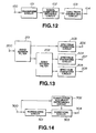
- FIG. 12 A conventional signal encoding apparatus will now be described by using FIG. 12 and figures succeeding thereto.
- acoustic signal waveform supplied through terminal 100 is transformed into signal frequency components by transform circuit 101.
- respective components are encoded by signal component encoding circuit 102.
- code train is generated by code train generating circuit 103, and is outputted from terminal 104.
- FIG. 13 An actual configuration of transform circuit 101 of FIG. 12 is shown in FIG. 13.
- signal delivered through terminal 200 (signal through terminal 100 of FIG. 12) is divided into signals in three frequency bands by two stages of band division filters 201, 202.
- band division filter 201 signal through terminal 200 is thinned so that it becomes equal to one half.
- band division filter 202 one of signals thinned into one half by the band division filter 201 is further thinned so that it becomes equal to one half (signal of terminal 200 is thinned so that it becomes equal to one fourth).
- bandwidths of two signals from band division filter 202 are one fourth of bandwidth of signal from terminal 200.
- Signals of respective bands divided into three bands as described above by these band division filters 201, 202 are caused to be spectrum signal components by spectrum transform circuits 203, 204, 205 for carrying out spectrum transform processing such as MDCT, etc.
- Outputs of these spectrum transform circuits 203, 204, 205 are sent to the above-mentioned signal component encoding circuit 102 of FIG. 12.
- FIG. 14 An actual configuration of signal component encoding circuit 102 of FIG. 12 is shown in FIG. 14.
- quantization is implemented to signal from the normalizing circuit 301 on the basis of quantization accuracy calculated by quantization accuracy determining circuit 302 from signal through the terminal 300.
- Output from the quantizing circuit 303 is outputted from terminal 304, and is sent to code train generating circuit 103 of FIG. 12.
- normalization coefficient information in the normalizing circuit 301 and quantization accuracy information in the quantization accuracy determining circuit 302 are included in addition to signal components quantized by the quantizing circuit 303.
- codes of respective signal components are extracted by code train decomposing circuit 401 from code train generated by the configuration of FIG. 12, which is supplied through terminal 400. Respective signal components are restored (reconstructed) by signal component decoding circuit 402 from those codes. Thereafter, inverse transform processing corresponding to transform processing of the transform circuit 101 of FIG. 12 is implemented by inverse transform circuit 403. Thus, acoustic waveform signal is obtained. This acoustic waveform signal is outputted from terminal 404.
- FIG. 16 An actual configuration of inverse transform circuit 403 of FIG. 15 is shown in FIG. 16.
- FIG. 16 corresponds to the example of configuration of the transform circuit shown in FIG. 13.
- Signals delivered from signal component decoding circuit 402 through terminals 501, 502, 503 are transformed by inverse spectrum transform circuits 504, 505, 506 for carrying out inverse spectrum transform processing corresponding to the spectrum transform processing in FIG. 13, respectively.
- Signals of respective bands obtained by these inverse spectrum transform circuits 504, 505, 506 are synthesized by two stages of band synthesis filters 507, 508.
- outputs of inverse spectrum transform circuits 505 and 506 are sent to band synthesis filter 507, at which they are synthesized. Further, output of the band synthesis filter 507 and output of the inverse spectrum transform circuit 504 are synthesized by band synthesis filter 508. Output of this band synthesis filter 508 is outputted from terminal 509 (terminal 404 of FIG. 15).
- FIG. 17 is a view for explaining an encoding method conventionally carried out in the encoding apparatus shown in FIG. 12.
- spectrum signal is a signal obtained by transform circuit of FIG. 13.
- FIG. 17 shows levels of absolute values of spectrum signals (signal components) by MDCT in terms of dB values.
- input signal is transformed into 64 spectrum signals every predetermined time block.
- Those spectrum signals are combined into groups (hereinafter referred to as encoding units) every five predetermined bands indicated by b1 to b5 in FIG. 17, and are caused to undergo normalization and quantization.
- bandwidths of respective encoding units are caused to be narrow on the lower frequency band side and are broad on the higher frequency band side so that control of occurrence of quantizing noise in correspondence with the property of the hearing sense can be conducted.
- bands where frequency components are quantized are fixed. For this reason, e.g., in the case where spectrum components concentrate on the portions in the vicinity of several specific frequencies, if attempt is made to quantize those spectrum components with sufficient accuracy, many bits must be allocated to a large number of spectrum components belonging to the same band as that of those spectrum components.
- normalization coefficient values are normalized on the basis of great normalization coefficient value determined by tone characteristic component, e.g., in the frequency band of b3 in the figure where tone characteristic component is included in signal.
- noise included in acoustic signal of tone characteristic where energies of spectrum components concentrate on a specific frequency or frequencies is generally very offensive to the ear as compared to noise applied to acoustic Signal where energies are gently distributed over a broad frequency band and is therefore great obstacle from a viewpoint of the hearing sense.
- spectrum components having great energy i.e., tone characteristic components are not quantized with sufficiently good accuracy, in the case where those spectrum components are caused to be waveform signals on the time base for a second time to synthesize it with blocks before and after, distortion between blocks becomes great and great connection distortion takes place when synthesized with waveform signals of adjacent time blocks, so there also results great obstacle from a viewpoint of the hearing sense.
- Typical encoding and decoding methods and apparatuses as discussed above are set forth in WO 89/10661-A1 and US 5,040,217.
- WO 89/10661-A1 certain frequency bands are not used at all and only certain other frequency bands are combined based on assumption by experience whether or not those frequency bands contain essential information.
- MDCT-transformation and variable length encoding are used in a one-channel system are used, information components being regarded as not essential being masked. Thus, both possible essential information (tone characteristic)and background information (noise characteristic) will get lost.
- an object of this invention is to provide a signal encoding apparatus which can improve efficiency of encoding without allowing sound quality of particularly acoustic signal of tone characteristic, a recording medium adapted so that signals processed by such signal encoding apparatus are recorded thereon or thereinto, and a signal decoding apparatus adapted for decoding encoded signal reproduced from such a recording medium, or transmitted from a signal encoding apparatus as mentioned above.
- the signal encoding apparatus of this invention carries out processing as described below.
- the first encoding means is operative so that, in encoding of the first signal, it normalizes amplitude information of respective tone characteristic components of the first signal by normalization coefficient thereafter to encode those normalized amplitude information.
- this signal encoding apparatus encodes respective frequency components of the respective tone characteristic components by a plurality of transform rules. Which one of the plurality of transform rules is used in implementation of encoding is determined by relative positional relationship on the frequency base between maximum frequency component and respective frequency components of the tone characteristic components.
- Transform rule applied to the maximum frequency component of the above-mentioned transform rules carries out a transform processing into shorter codes with respect to frequency components having information having greater amplitude value information.
- Transform rule applied to other respective frequency components of maximum frequency component of the above-mentioned transform rules carries out a transform processing into shorter codes with respect to frequency components having information of smaller amplitude value information.
- the input signal is acoustic signal.
- the first encoding means of the signal encoding apparatus of this invention normalizes and quantizes amplitude information of respective tone characteristic components of the first signal by normalization coefficients to encode them, and omits amplitude information of the maximum frequency component in this encoding.
- the signal encoding apparatus of this invention in this case carries out a processing as described below.
- the separating means allows the tone characteristic components to overlap with each other on the frequency base to carry out separation of the first signal.
- Values of the normalization coefficients are set so that according as those values become smaller, accuracy becomes higher.
- input signal is acoustic signal.
- a recording medium of this invention is adapted so that a signal consisting of tone characteristic components encoded so as respectively have different lengths and a second signal consisting of other components are recorded thereonto or thereinto.
- amplitude information of respective tone characteristic components of the first signal are normalized by normalization coefficients and encoded.
- respective frequency components of the tone characteristic components are encoded by a plurality of transform rules. Any one of which plural transform rules is used in implementation of encoding is determined by relative positional relationship on the frequency base between maximum frequency component and respective frequency components of tone characteristic components.
- Transform rule applied to the maximum frequency component of the above-mentioned transform rules carries out a transform processing into shorter codes with respect to frequency components having information of greater amplitude values.
- Transform rule applied to other respective frequency components of the maximum frequency component of the above-mentioned transform rule carries out a transform processing into shorter codes with respect to frequency components having information of smaller amplitude values.
- signal to be recorded is acoustic signal.
- a recording medium of this invention is adapted so that a first signal consisting of tone characteristic components and a second signal consisting of other components are recorded in a manner separate from each other.
- signals obtained by normalizing and quantizing amplitude information of tone characteristic components of the first signal to encode them are recorded.
- information except for information obtained by normalizing and quantizing amplitude information of the maximum frequency are recorded as the first signals.
- recording is made in such a manner that tone characteristic components of the first signal overlap with each other on the frequency base. Normalization coefficients for the normalization are set so that according as those values become smaller, the accuracy becomes higher.
- a signal decoding apparatus of this invention comprises first decoding means for decoding a first signal consisting of tone characteristic components encoded so that they respectively have different lengths, second decoding means for decoding a second signal consisting of other components, and synthetic inverse transforming means for synthesizing respective signals to inversely transform them, or inversely transforming respective signals to synthesize them.
- the signal decoding apparatus of this invention is featured as below. Namely, amplitude information of respective tone characteristic components of the first signal are normalized by normalization coefficients and are encoded. Moreover, respective frequency components of the tone characteristic components are encoded by a plurality of transform rules. Any one of which plural transform rules is used in implementation of encoding is determined by relative positional relationship on the frequency base between maximum frequency component and respective frequency components of tone characteristic components. Transform rule applied to maximum frequency component of the above-mentioned transform rules carries out a transform processing into shorter codes with respect to frequency components having information of greater amplitude values. Transform rule applied to components except for the maximum frequency component of the above-mentioned transform rules carries out a transform processing into shorter codes with respect to frequency components having information of smaller amplitude values. In this case, output signal is acoustic signal.
- signal decoding apparatus of this invention comprises first decoding means for decoding a first signal consisting of tone characteristic components encoded in the state where information obtained by normalizing and quantizing amplitude information of maximum frequency component is excluded, second decoding means for decoding a second signal consisting of other components, and synthetic inverse transforming means for synthesizing respective signals to inversely transform them, or to inversely transform respective signals to synthesize them.
- tone characteristic components of the first signal are encoded in the state overlapping with each other on the frequency base.
- normalization coefficients for the normalization are set so that according as those values become smaller, accuracy becomes higher.
- encoding of variable length is effectively applied to signals of tone characteristic components, thereby realizing more efficient encoding.
- spectrum coefficient where absolute value is maximum e.g., only code information of positive and negative is encoded, thereby realizing more efficient encoding.
- FIG. 1 is a circuit diagram showing, in a block form, outline of the configuration of an encoding apparatus of an embodiment according to this invention.
- FIG. 2 is a circuit diagram showing, in a block form, outline of the configuration of a decoding apparatus of the embodiment according to this invention.
- FIG. 3 is a flowchart showing flow of processing in signal component separating circuit according to this invention.
- FIG. 4 is a view for explaining separation of tone characteristic component in signal encoding of this invention.
- FIG. 5 is a view for explaining noise characteristic component in which tone characteristic components are removed from original spectrum signal in signal encoding of this invention.
- FIG. 6 is a view showing an example of spectrum signal.
- FIG. 7 is a view showing a signal in which signal obtained by encoding and decoding one tone characteristic component is subtracted from the spectrum signal of FIG. 6.
- FIG. 8 is a view for explaining transform rule with respect to spectrum of tone characteristic components in this invention.
- FIG. 9 is a circuit diagram showing, in a block form, actual configuration of a tone characteristic encoding circuit of FIG. 1.
- FIG. 10 is a circuit diagram showing, in a block form, actual configuration of tone characteristic decoding circuit of FIG. 2.
- FIG. 11 is a view showing for explaining recording of code train obtained after undergone encoding by signal encoding system of this invention.
- FIG. 12 is a circuit diagram showing, in a block form, outline of the configuration of a conventional encoding apparatus.
- FIG. 13 is a circuit diagram showing, in a block form, actual configuration of transform circuits of this embodiment and conventional encoding apparatus.
- FIG. 14 is a circuit diagram showing, in a block form, actual configuration of a signal component encoding circuit of this invention and conventional encoding apparatus.
- FIG. 15 is a circuit diagram showing, in a block form, outline of the configuration of conventional decoding apparatus.
- FIG. 16 is a circuit diagram showing, in a block form, actual configuration of inverse transform circuits applied to this invention and conventional decoding apparatus.
- FIG. 17 is a view for explaining encoding method by the prior art.
- FIG. 18 is a circuit diagram showing, in a block form, another example of synthetic inverse transform section constituting decoding apparatus according to this invention.
- FIG. 19 is a circuit diagram showing, in a block form, another embodiment of an encoding apparatus according to this invention.
- FIG. 20A is a code table showing transform rule with respect to maximum spectrum coefficient.
- FIG. 20B is a code table showing transform rule of peripheral spectrum coefficients in the case where the same transform rule is used with respect to all peripheral components.
- FIG. 1 shows outline of the configuration of a signal encoding apparatus of an embodiment according to this invention.
- terminal 600 is supplied with acoustic waveform signal.
- This acoustic signal waveform is transformed into signal frequency components by transform circuit 601, and is then sent to signal component separating circuit 602.
- tone characteristic component separating circuit 602 signal frequency components obtained by transform circuit 601 are separated into tone characteristic components having sharp spectrum distribution and signal frequency components except for the above, i.e., noise characteristic component having flat spectrum distribution.
- the tone characteristic components having sharp spectrum distribution of these separated frequency components are encoded by tone characteristic component encoding circuit 603, and the noise characteristic components which are signal frequency components except for the above are encoded by noise characteristic component encoding circuit 604.
- Signal outputted from tone characteristic component encoding circuit 603 is caused to undergo variable length encoding at variable length encoding circuit 601.
- Outputs from the variable length encoding circuit 610 and the noise characteristic component encoding circuit 604 are inputted to code train generating circuit 605, at which code train is generated. The code train thus generated is outputted therefrom.
- ECC encoder 606 adds error correction code to the code train from code train generating circuit 605. Output from ECC encoder 606 is modulated by EFM circuit 607. The modulated signal thus obtained is delivered to recording head 608. This recording head 608 records the code train outputted from EFM circuit 607 onto disc 609.
- transform circuit 601. configuration similar to that of the FIG. 13 mentioned above may be employed as transform circuit 601.
- input signal may be directly transformed into spectrum signal by MDCT, and DFT or DCT, etc. may be used as spectrum transform processing in place of MDCT.
- signal may be divided into signals in frequency components by band division filter as previously described, since encoding this invention is effectively exerted particularly in the case where energies concentrate on a specific frequency or frequencies, employment of a method of transformation into frequency components by the above-described spectrum transform processing by which a large number of frequency components are obtained by relatively small operation quantity is convenient.
- tone characteristic component encoding circuit 603 and the noise characteristic component encoding circuit 604 may be fundamentally realized by configuration similar to that of the FIG. 14 mentioned above.
- FIG. 2 shows outline of the configuration of a signal decoding apparatus of the embodiment according to this invention for decoding signal encoded by the encoding apparatus of FIG. 1.
- code train reproduced through reproducing head 708 from disc 609 is delivered to EF demodulating circuit (labeled demodulation of EFM data) 709.
- This EF demodulating circuit 709 demodulates inputted code train.
- the demodulated code train is delivered to ECC decoder 710, at which error correction is carried out.
- Code train decomposing circuit 701 recognizes, on the basis of tone characteristic component information No. of error-corrected code train, which portion of code train belongs to tone characteristic component code to separate the inputted code train into tone characteristic component codes and the noise characteristic component codes.
- code train separating circuit 701 separates position information of tone characteristic component from the inputted code train to output it to synthesis circuit 704 of the succeeding stage.
- tone characteristic component codes are caused to undergo variable length decoding by variable length decoding circuit 715, and are then sent to tone characteristic component decoding circuit 702, and the noise characteristic component codes are sent to noise characteristic component decoding circuit 703, at which inverse quantization and release of normalization are respectively carried out and respective components are decoded. Thereafter, decoded signals from tone characteristic component decoding circuit 702 and noise characteristic component decoding circuit 703 are delivered to synthesis circuit 704 for carrying out synthesis corresponding to separation at the signal component separating circuit 602 of FIG. 1.
- the synthesis circuit 704 adds decoded signal of tone characteristic component to a predetermined position of decoded signal of noise characteristic component on the basis of position information of tone characteristic component delivered from code train separating circuit 701 to thereby carry out synthesis on the frequency base of noise characteristic component and tone characteristic component. Further, the decoded signal thus synthesized is caused to undergo inverse transform processing at inverse transform circuit 705 for carrying out inverse transform processing corresponding to transform processing at the transform circuit 601 of FIG. 1 so that signal on the frequency base is caused to be original waveform signal on the time base for a second time. Output waveform signal from the inverse transform circuit 705 is outputted from terminal 707. It should be noted that processing order of inverse transformation and synthesis may be opposite to the above.
- synthetic inverse transform section 711 in FIG. 2 is constructed as shown in FIG. 18.
- Inverse transform circuit 712 constituting the synthetic inverse transform section 711 inverse-transforms decoded signal of noise characteristic component on the frequency base from noise characteristic component decoding circuit 703 into noise characteristic component signal on the time base.
- Inverse transform circuit 713 arranges decoded signal of tone characteristic component from tone characteristic component decoding circuit 702 at position on the frequency base indicated by position information of tone characteristic component delivered from code train separating circuit 701 to inverse-transform it to generate tone characteristic component signal on the time base.
- Synthesis circuit 714 synthesizes noise characteristic component signal on the time base from inverse transform circuit 712 and tone characteristic component signal on the time base from inverse transform circuit 713, thus to generate original waveform signal.
- FIG. 3 shows flow of actual processing for separating tone characteristic component in signal component separating circuit 602 of encoding apparatus of FIG. 1.
- I denotes No. of spectrum signals
- N indicates total number of spectrum signals
- P, R indicate predetermined coefficients.
- the above-mentioned tone characteristic component is determined on the basis of the following consideration. Namely, in the case where the absolute value of a certain spectrum signal is greater than other spectrum components when locally viewed, the difference between the absolute value and the maximum value of absolute values of spectrum signals in the corresponding time block (block in spectrum transform processing) is a predetermined value or more, and the sum of this spectrum and neighboring spectrum components (e.g., spectrum components adjoining thereto in both directions) indicates a predetermined ratio or more with respect to energy within a predetermined band including those spectrum components, this spectrum signal and, e.g., spectrum signals adjoining thereto in both directions are considered to be tone characteristic components.
- a predetermined band for comparison of the ratio of energy distribution there may be employed a band such that bandwidth is narrow in a lower frequency band and is broad in higher frequency band in correspondence with, e.g., critical bandwidths by taking the property of the hearing sense into consideration.
- step S1 maximum spectrum absolute value is substituted for variable AO.
- step S2 No. I of spectrum signal is set to 1.
- step S3 a certain spectrum absolute value within a certain time block is substituted for variable A.
- step S4 whether or not the spectrum absolute value is the maximum absolute value spectrum greater than other spectrum components when locally viewed is judged. As a result, when it is not the maximum absolute value spectrum (No), the processing operation proceeds to step S10. In contrast, in the case where it is the maximum absolute value spectrum (Yes), the processing operation proceeds to step S5.
- step S5 the ratio between variable A of the maximum absolute value spectrum in corresponding time block including the maximum absolute value spectrum and variable AO of the maximum spectrum absolute value and coefficient P indicating a predetermined magnitude are compared (A/A 0 > P).
- A/A 0 is grater than P (Yes)
- the processing operation proceeds to step S6.
- A/A 0 is less than P (No)
- the processing operation proceeds to step S10.
- the energy value of neighboring spectrum e.g., sum of energies of spectrum components adjoining to corresponding spectrum in both directions
- the energy value within a predetermined band including the maximum absolute value spectrum and the neighboring spectrums thereof is substituted for variable Y.
- step S8 the ratio between variable X of the energy value and variable Y of energy value within a predetermined band and coefficient R indicating a predetermined ratio are compared (X/Y>R).
- X/Y is greater than R (Yes)
- the processing operation proceeds to step S9.
- X/Y is less than R (No)
- the processing operation proceeds to step S10.
- step S9 in the case where the energy in the maximum absolute value spectrum and the neighboring spectrum components thereof indicates a predetermined ratio or more with respect to energy within a predetermined band including those spectrum components, signal of its maximum absolute value spectrum component and, e.g., signals of spectrum components adjoining thereto in both directions are considered to be tone characteristic component to register this fact.
- Signal component separating circuit 602 delivers frequency component or components judged to be tone characteristic component by the above-described processing to tone characteristic encoding circuit 603, and delivers other frequency components as noise characteristic component to noise characteristic component encoding circuit 604. Moreover, signal component separating circuit 602 delivers No. of frequency information judged to be tone characteristic component and information of that position to code train generating circuit 605.
- FIG. 4 shows the state of one example where tone characteristic components are separated from frequency components in a manner as described above.
- tone characteristic components indicated by TC A , TC B , TC C , TC D in the figure are extracted. Since these tone characteristic components are distributed in the state where they concentrate on small number of spectrum signals as in the example of FIG. 4, even if these components are quantized with good accuracy, a large number of bits are not so required as a whole. For this reason, while tone characteristic components are once normalized thereafter to quantize the normalized components to thereby improve efficiency of encoding, since spectrum signals constituting the tone characteristic component are relatively small in number, processing of normalization and/or re-quantization may be omitted thus to simplify the apparatus.
- FIG. 5 shows the example where noise characteristic components in which tone characteristic components are excluded from original spectrum signal is indicated.
- tone characteristic components are excluded (caused to be zero) as described above from the original spectrum signal in respective bands b1 ⁇ b5.
- normalization coefficients in respective encoding units become small value. Accordingly, quantizing noises generated can be reduced even with small number of bits.
- tone characteristic component extracting circuit 802 Spectrum signal obtained by transform circuit 601 is delivered to tone characteristic component extracting circuit 802 through switch 801 controlled by control circuit 808.
- This tone characteristic component extracting circuit 802 discriminates tone characteristic component by the above-described processing of FIG. 3 to deliver only the discriminated tone characteristic component to tone characteristic component encoding circuit 603.
- tone characteristic component extracting circuit 802 outputs the number of tone characteristic component information and its center position information to code train generating circuit 605.
- the tone characteristic component encoding circuit 603 implements normalization and quantization to the inputted tone characteristic component to deliver the normalized and quantized tone characteristic component to variable length encoding circuit 610 and local decoder 804.
- This variable length encoding circuit 610 implements variable length encoding to the normalized and quantized tone characteristic component to deliver the variable length code thus obtained to code train generating circuit 605.
- This local decoder 804 implements inverse quantization and releasing of normalization to the normalized and quantized tone characteristic component to decode signal of original tone characteristic component. It should be noted that quantizing noise would be included in decoded signal at this time.
- Output from local decoder 804 is delivered to adder 805 as the first decoded signal.
- original spectrum signal from transform circuit 601 is delivered to adder 805 through switch 806 controlled by switch control circuit 808. This adder 805 subtracts the first decoded signal from the original spectrum signal to output the first difference signal.
- the above-mentioned first difference signal is delivered as noise characteristic component to noise characteristic component encoding circuit 604 through switch 807 controlled by switch control circuit 808.
- processing sequence of extraction, encoding, decoding, difference determination of tone characteristic component is repeated, the first difference signal is delivered to tone characteristic component extracting circuit 802 through switch 801.
- Tone characteristic component extracting circuit 802, tone characteristic component encoding circuit 603, local decoder 804 carry out processing similar to the above.
- the second decoded signal obtained is delivered to adder 805.
- the first difference signal is delivered to adder 805 through switch 806.
- Adder 805 subtracts the second decoded signal from the first difference signal to output the second difference signal. Further, in the case where processing sequence of extraction, encoding, decoding, difference determination of tone characteristic component is completed by two times of processing sequence, the second difference signal is delivered to noise characteristic component encoding circuit 604 through switch 807 as noise characteristic component. In the case where processing sequence of extraction, encoding, decoding, difference determination of tone characteristic component is further repeated, processing similar to the above is carried out by tone characteristic component extracting circuit 802, tone characteristic component encoding circuit 603, local decoder 804 and adder 805.
- Switch control circuit 808 holds threshold value of tone characteristic component information number, and controls switch 807 so that extraction, encoding, decoding, difference determination processing sequence of tone characteristic component is completed in the case where tone characteristic component information number obtained from the tone characteristic component extracting circuit is above the threshold value.
- tone characteristic component encoding circuit 603 there can be employed a processing such that when tone characteristic component is ceased to be extracted, extraction, encoding, decoding and difference determination processing sequence of tone characteristic component is completed.
- FIGS. 6 and 7 are views for explaining such a method, wherein FIG. 7 shows a signal in which signal obtained by encoding one tone characteristic component to decode the encoded signal is subtracted from spectrum signal of FIG. 6.
- tone characteristic component components indicated by broken lines in the figure are further extracted from the spectrum signal of FIG. 7 as tone characteristic component, thereby making it possible to improve encoding accuracy of spectrum signal.
- tone characteristic component components indicated by broken lines in the figure are further extracted from the spectrum signal of FIG. 7 as tone characteristic component, thereby making it possible to improve encoding accuracy of spectrum signal.
- high accuracy encoding can be carried out.
- this method even if the upper limit of the number of bits for quantizing tone characteristic component is set to low value, encoding accuracy can be sufficiently high. Accordingly, there is also the merit that the number of bits for recording quantization bit number can be reduced.
- the method of extracting tone characteristic components in a multi-stage manner as stated above can be applied necessarily not only to the case where a signal equivalent to a signal obtained by encoding tone characteristic component to decode the encoded signal is subtracted from the original spectrum signal, but also to the case where spectrum signal of the extracted tone characteristic component is caused to be zero.
- the expression that "signal from which tone characteristic components are separated", etc. should be considered to include the above-mentioned both cases.
- variable length code to allocate shorter code length to pattern of high frequency as described in, e.g., D.A. Huffman: A Method for Construction of Minimum Redundancy Codes, Proc. I.R.E., 40, P.1098 (1952) is employed, thereby making it possible to carry out efficient encoding.
- respective tone characteristic components are separated into maximum spectrum coefficient and peripheral spectrum coefficients to apply different variable length codes to respective spectrum coefficients, thereby realizing efficient encoding.
- tone characteristic components have very sharp spectrum distribution on the frequency base
- distribution of values in the case where peripheral spectrum coefficients are normalized and quantized is greatly affected by relative positional relationship on the frequency base between those peripheral spectrum coefficients and maximum spectrum coefficient.
- the method of classification of relative position there may be employed a method of carrying out classification by absolute values of differences on the frequency base with respect to maximum spectrum components.
- variable length encoding may be carried out by the same transform rule with respect to all peripheral spectrum coefficients for the purpose of simplifying processing.
- FIG. 20A An example of code table indicating transform rule with respect to maximum spectrum coefficient is shown in FIG. 20A.
- FIG. 20B An example of code table showing transform rule of peripheral spectrum coefficients in the case where the same transform rule is used with respect to all peripheral spectrum coefficients is shown in FIG. 20B.
- Maximum spectrum coefficient after normalization and quantization i.e., quantized value of maximum spectrum is equal to a value closer to +1 or -1 as described above.
- FIG. 20A if 00 and 01 which are codes having code lengths shorter than code lengths allocated to other values, it is possible to efficiently encode maximum spectrum coefficient.
- peripheral spectrum coefficients after normalization and quantization i.e., quantized values of peripheral spectrum components become equal to a value closer to zero as described above.
- FIG. 20 if 0 which has code length shorter than code lengths allocated to other values is allocated to the above-mentioned 0 (zero), it is possible to efficiently encode peripheral spectrum coefficients.
- FIG. 9 shows an actual example of variable length encoding circuit 610 of FIG. 1.
- tone characteristic components inputted to terminal 800 are classified (divided) by relative position on the frequency base with respect to maximum spectrum component by control circuit 801.
- the spectrum components thus classified are sent to maximum spectrum coefficient encoding circuit 802, peripheral spectrum coefficient encoding circuit 803 and peripheral spectrum coefficient encoding circuit 804 respectively corresponding thereto.
- those spectrum components are encoded on the basis of the above-described corresponding transform rules.
- Encoded outputs from respective encoding circuits 802, 803, 804 are outputted from output terminal 805 through control circuit 801.
- FIG. 10 shows an actual example of the above-described variable length decoding circuit 715 of FIG. 2.
- tone characteristic component codes inputted to input terminal 900 are classified in correspondence with the classification of FIG. 9.
- the codes thus classified are sent to maximum spectrum coefficient decoding circuit 902, peripheral spectrum coefficient decoding circuit 903 and peripheral spectrum coefficient decoding circuit 904 respectively corresponding thereto.
- those codes are decoded on the basis of inverse transform rules respectively corresponding to the above-described transform rules.
- Decoded outputs from respective decoding circuits 902, 903, 904 are outputted from output terminal 905 through control circuit 901.
- FIG. 11 shows the example in the case where spectrum signal of FIG. 4 is encoded by the encoding apparatus of this embodiment. Code trains thus obtained are recorded onto recording medium.
- tone characteristic component information No. tnc (e.g., 4 in the example of FIG. 11) is first recorded onto recording medium. Then, tone characteristic component information tc A , tc B , tc C , tc D and noise characteristic components information nc 1 , nc 2 , nc 3 , nc 4 , nc 5 are recorded in order recited.
- tone characteristic component information tc A , tc B , tc C , tc D center position information CP indicating position of center spectrum of tone characteristic component (e.g., 15 in the case of, e.g., tone characteristic component tc B ), quantization accuracy information indicating the number of bits for quantization (e.g., 6 in the case of, e.g., tone characteristic component tc B ) and normalization coefficient information are recorded along with respective signal component information SC a , SC b , SC c , SC d , SC e which were caused to undergo normalization and quantization, and are then caused to undergo variable length encoding.
- transform rules of variable length encoding are determined in advance every quantization accuracy.
- the decoding apparatus carries out decoding of variable length codes by making reference to quantization accuracy information.
- quantization accuracy information e.g. 2 in the case of noise characteristic component nc 1
- normalization coefficient information are recorded along with normalized and quantized respective signal component information SC 1 , SC 2 , ⁇ , SC 8 .
- quantization accuracy information is zero
- encoding is not actually carried out in that encoding unit.
- quantization accuracy is fixedly determined every band similarly to the above, it is unnecessary to record quantization accuracy information.
- FIG. 11 shows the embodiment of kind and order of information recorded on a recording medium.
- information up to signal component information SC a , SC b , SC c , SC d , SC e are codes of variable length, and their lengths are not fixed.
- tone characteristic encoding circuit 603 carries out normalization and quantization with respect to frequency components except for maximum spectrum component of respective tone characteristic components. It should be noted that there may be employed a configuration in which normalization and quantization are carried out with respect to all respective tone characteristic components including maximum spectrum as well at tone characteristic component encoding circuit 603, and quantized value corresponding to maximum spectrum is not outputted at code train generating circuit 605 of the succeeding stage.
- signal component information SC c includes only codes indicating positive and negative in the example of FIG. 11.
- value approximate to amplitude information of maximum spectrum is primarily selected as normalization coefficient
- normalization coefficients are recorded on recording medium
- approximate value of maximum spectrum can be obtained from codes indicating positive and negative and normalization coefficient information.
- approximate value of maximum spectrum can be obtained only from phase component.
- encoding in this invention can be applied to encoding of general waveform signal. It should be noted that encoding in this invention is particularly effective in carrying out efficient encoding with respect to acoustic signal in which tone characteristic components have significant meaning from a viewpoint of the hearing sense.
- disc 609 of the above-described embodiment may be, e.g., magneto-optical recording medium, optical recording medium, or phase change type optical recording medium, etc.
- semiconductor memory or IC card, etc. may be used in addition to tape-shaped recording medium as recording medium which is substitutive for disc 609.
- noise characteristic components may be also caused to undergo variable length encoding.
- the signal encoding apparatus in transforming input signal into frequency components to separate the transformed output into a first signal consisting of tone characteristic components and a second signal consisting of other components to encode these first and second signals, respective signal components of the first signal are encoded so that they have different code lengths, thereby making it possible to extremely efficiently encode tone characteristic components of signal decomposed into tone characteristic components and noise characteristic components.
- encoding efficiency with respect to the entirety of signal waveform can be improved. Accordingly, if such compressed signals are recorded onto or into recording medium, recording capacity can be effectively utilized.
- satisfactory signals e.g., acoustic signals can be obtained.
Description
Claims (28)
- A signal encoding apparatus adapted for encoding an input signal, comprising:the first encoding means including variable length encoding means (610) for implementing variable length encoding to respective signal components of the first signal.transforming means (601) for transforming an input signal into a block of frequency components by spectrum transform processing, each frequency component being characterized by an energy distribution,separating means (602) for separating all the frequency components of the spectrum of the output of the transforming means (601) into a first signal consisting of all tone characteristic components and a second signal consisting of all other components;first encoding means (603) for encoding the first signal; andsecond encoding means (604) for encoding the second signal,
- A signal encoding apparatus as set forth in claim 1, wherein the first encoding means (603) is operative so that, in implementation of encoding of the first signal, it normalizes amplitude information of respective tone characteristic components of the first signal by normalization coefficients thereafter to implement variable length encoding thereto.
- A signal encoding apparatus as set forth in claim 1 or 2, wherein the variable length encoding means implements variable length encoding to respective frequency components of the respective tone characteristic components by a plurality of transform rules.
- A signal encoding apparatus as set forth in claim 3, wherein which any one of the plurality of transform rules is used in implementation of encoding is determined by relative positional relationship on the frequency base between a maximum frequency component and respective frequency components of the tone characteristic components.
- A signal encoding apparatus as set forth in claim 3, wherein a transform rule applied to a maximum frequency component of the transform rules is adapted to carry out a transform processing into shorter codes with respect to frequency components having information of greater amplitude values.
- A signal encoding apparatus as set forth in claim 3, wherein a transform rule applied to other respective frequency components of a maximum frequency component of the transform rules is adapted to carry out a transform processing into shorter codes with respect to frequency components having information of smaller amplitude values.
- A signal encoding apparatus as set forth in claim 1, wherein the input signal is acoustic signal.
- A signal decoding apparatus adapted for decoding an encoded signal encoded according to the method of anyone of claims 15 to 20 or by means of the apparatus of anyone of claims 1 to 7, comprising:first decoding means (702, 715) for decoding a first signal consisting of all tone characteristic components of the spectrum caused to undergo variable length encoding;second decoding means (703) for decoding a second signal consisting of all other components of the spectrum; andsynthetic inverse transforming means (711) for synthesizing respective signals to inversely spectrum transform them, or inversely spectrum transforming respective signals to synthesize them.
- A signal decoding apparatus as set forth in claim 8, wherein amplitude information of respective tone characteristic components of the first signal are normalized by normalization coefficients and are encoded.
- A signal decoding apparatus as set forth in claim 8 or 9, wherein the first decoding means (715) decodes the first signal by a plurality of transform rules.
- A signal decoding apparatus as set forth in claim 10, wherein any one of the plurality of transform rules in implementation of decoding is determined by relative positional relationship on the frequency base between a maximum frequency component and respective frequency components of tone characteristic components.
- A signal decoding apparatus as set forth in claim 10, wherein a transform rule applied to a maximum frequency component of the transform rules is adapted to carry out a transform processing into shorter codes with respect to frequency components having information of greater amplitude values.
- A signal decoding apparatus as set forth in claim 10, wherein a transform rule applied to components except for a maximum frequency component of the transform rules is adapted to carry out a transform processing into shorter codes with respect to frequency components having information of smaller amplitude values.
- A signal decoding apparatus as set forth in anyone of claims 8 to 13, wherein the synthetic inverse transforming means (711) outputs an acoustic signal.
- A signal encoding method for encoding an input signal, comprising the steps of :transforming (601) an input signal into a block of frequency components by spectrumtransform processing, each frequency component being characterized by an energy distribution;separating (602) all the frequency components of the spectrum into a first signal consisting of all tone characteristic components and a second signal consisting of all other components, each tone component characteristic having a sharp energy distribution relative to energy distributions of frequency components in the block;implementing variable length encoding (603, 610) to the first signal;
andencoding (604) the second signal. - A signal encoding method as set forth in claim 15, wherein amplitude information of the first signal are normalized by normalization coefficients, and are then caused to undergo the variable length encoding.
- A signal encoding method as set forth in claim 15 or 16, wherein the first signal is caused to undergo variable length encoding (610) on the basis of a plurality of different transform rules.
- A signal encoding method as set forth in claim 17, wherein any one of the plurality of different transform rules is selected on the basis of relative positional relationship on the frequency base between a maximum frequency component of signal components of the first signal and other frequency components.
- A signal encoding method as set forth in claim 17, wherein a transform rule applied to a maximum frequency component of the transform rule is adapted to carry out a transform processing into shorter codes with respect to information of greater amplitude values.
- A signal encoding method as set forth in claim 17, wherein a transform rule applied to respective frequency components except for a maximum frequency component of the transform rules is adapted to allocate shorter codes with respect to information of smaller amplitude values.
- A signal decoding method for decoding an encoded signal, encoded according to the method of anyone of claims 15 to 20 or by means of the apparatus of anyone of claims 1 to 7, comprising the steps of first decoding (702, 715) a first signal consisting of all tone characteristic components of the spectrum caused to undergo variable length encoding,second decoding (703) a second signal consisting of all other components of the spectrum,processing (711) by synthesizing the respective decoded signals and inversely spectrum transforming the synthesized signals or, vice versa, inversely spectrum transforming the respective decoded signals and synthesizing the inversely transformed signals.
- A decoding method as set forth in claim 21 comprising inversely normalizing the amplitude information of respective tone characteristic components of the first signal which are normalized by normalization coefficients and are encoded.
- A decoding method as set forth in claim 21 or 22, wherein in the first decoding step (715) the first signal is decoded by a plurality of transform rules.
- A decoding method as set forth in claim 23, wherein anyone of the plurality of transform rules in implementation of decoding is determined by relative positional relationship on the frequency base between a maximum frequency component and respective frequency components of tone characteristic components.
- A decoding method as set forth in claim 23, wherein a transform rule applied to a maximum frequency component of the transform rules is adapted to carry out a transform processing into shorter codes with respect to frequency components having information of greater amplitude values.
- A decoding method as set forth in claim 23, wherein a transform rule applied to components except for a maximum frequency component of the transform rules is adapted to carry out a transform processing into shorter codes with respect to frequency components having information of smaller amplitude values.
- A decoding method as set forth in anyone of claims 21 to 26, wherein in the precessing step (711) there is outputted an acoustic signal.
- A recording medium (609) recorded with encoded signals being encoded by the encoding method as set forth in anyone of claims 15 to 20, or by the encoding apparatus as set forth in anyone of claims 1 to 7 implementing the encoding method of anyone of claims 15 to 20.
Priority Applications (1)
| Application Number | Priority Date | Filing Date | Title |
|---|---|---|---|
| EP00125009A EP1083674B1 (en) | 1993-06-30 | 1994-06-29 | Digital signal encoding device, its decoding device, and its recording medium |
Applications Claiming Priority (4)
| Application Number | Priority Date | Filing Date | Title |
|---|---|---|---|
| JP18332293 | 1993-06-30 | ||
| JP183322/93 | 1993-06-30 | ||
| JP18332293 | 1993-06-30 | ||
| PCT/JP1994/001056 WO1995001680A1 (en) | 1993-06-30 | 1994-06-29 | Digital signal encoding device, its decoding device, and its recording medium |
Related Child Applications (1)
| Application Number | Title | Priority Date | Filing Date |
|---|---|---|---|
| EP00125009A Division EP1083674B1 (en) | 1993-06-30 | 1994-06-29 | Digital signal encoding device, its decoding device, and its recording medium |
Publications (3)
| Publication Number | Publication Date |
|---|---|
| EP0663739A1 EP0663739A1 (en) | 1995-07-19 |
| EP0663739A4 EP0663739A4 (en) | 1998-09-09 |
| EP0663739B1 true EP0663739B1 (en) | 2001-08-22 |
Family
ID=16133682
Family Applications (2)
| Application Number | Title | Priority Date | Filing Date |
|---|---|---|---|
| EP94919822A Expired - Lifetime EP0663739B1 (en) | 1993-06-30 | 1994-06-29 | Digital signal encoding device, its decoding device, and its recording medium |
| EP00125009A Expired - Lifetime EP1083674B1 (en) | 1993-06-30 | 1994-06-29 | Digital signal encoding device, its decoding device, and its recording medium |
Family Applications After (1)
| Application Number | Title | Priority Date | Filing Date |
|---|---|---|---|
| EP00125009A Expired - Lifetime EP1083674B1 (en) | 1993-06-30 | 1994-06-29 | Digital signal encoding device, its decoding device, and its recording medium |
Country Status (10)
| Country | Link |
|---|---|
| US (1) | US5765126A (en) |
| EP (2) | EP0663739B1 (en) |
| JP (1) | JP3721582B2 (en) |
| KR (1) | KR100368854B1 (en) |
| CN (2) | CN1099777C (en) |
| BR (1) | BR9405445A (en) |
| DE (2) | DE69432538T2 (en) |
| PL (2) | PL173718B1 (en) |
| RU (1) | RU2131169C1 (en) |
| WO (1) | WO1995001680A1 (en) |
Families Citing this family (35)
| Publication number | Priority date | Publication date | Assignee | Title |
|---|---|---|---|---|
| TW327223B (en) * | 1993-09-28 | 1998-02-21 | Sony Co Ltd | Methods and apparatus for encoding an input signal broken into frequency components, methods and apparatus for decoding such encoded signal |
| JP3250376B2 (en) * | 1994-06-13 | 2002-01-28 | ソニー株式会社 | Information encoding method and apparatus, and information decoding method and apparatus |
| JP3277699B2 (en) * | 1994-06-13 | 2002-04-22 | ソニー株式会社 | Signal encoding method and apparatus, and signal decoding method and apparatus |
| US6167093A (en) * | 1994-08-16 | 2000-12-26 | Sony Corporation | Method and apparatus for encoding the information, method and apparatus for decoding the information and method for information transmission |
| US5774837A (en) * | 1995-09-13 | 1998-06-30 | Voxware, Inc. | Speech coding system and method using voicing probability determination |
| JP3282661B2 (en) * | 1997-05-16 | 2002-05-20 | ソニー株式会社 | Signal processing apparatus and method |
| EP0887958B1 (en) * | 1997-06-23 | 2003-01-22 | Liechti Ag | Method for the compression of recordings of ambient noise, method for the detection of program elements therein, devices and computer program therefor |
| US6269332B1 (en) * | 1997-09-30 | 2001-07-31 | Siemens Aktiengesellschaft | Method of encoding a speech signal |
| US6965697B1 (en) * | 1998-07-15 | 2005-11-15 | Sony Corporation | Coding apparatus and method, decoding apparatus and method, data processing system, storage medium, and signal |
| US6311154B1 (en) | 1998-12-30 | 2001-10-30 | Nokia Mobile Phones Limited | Adaptive windows for analysis-by-synthesis CELP-type speech coding |
| US6298322B1 (en) * | 1999-05-06 | 2001-10-02 | Eric Lindemann | Encoding and synthesis of tonal audio signals using dominant sinusoids and a vector-quantized residual tonal signal |
| US20020049586A1 (en) * | 2000-09-11 | 2002-04-25 | Kousuke Nishio | Audio encoder, audio decoder, and broadcasting system |
| US6801887B1 (en) | 2000-09-20 | 2004-10-05 | Nokia Mobile Phones Ltd. | Speech coding exploiting the power ratio of different speech signal components |
| ATE338999T1 (en) * | 2001-10-19 | 2006-09-15 | Koninkl Philips Electronics Nv | DIFFERENTIAL CODING IN THE FREQUENCY RANGE OF SINE MODEL PARAMETERS |
| CN1308913C (en) * | 2002-04-11 | 2007-04-04 | 松下电器产业株式会社 | Encoder and decoder |
| US6973579B2 (en) | 2002-05-07 | 2005-12-06 | Interdigital Technology Corporation | Generation of user equipment identification specific scrambling code for the high speed shared control channel |
| JP3900000B2 (en) * | 2002-05-07 | 2007-03-28 | ソニー株式会社 | Encoding method and apparatus, decoding method and apparatus, and program |
| KR100462611B1 (en) * | 2002-06-27 | 2004-12-20 | 삼성전자주식회사 | Audio coding method with harmonic extraction and apparatus thereof. |
| MXPA05005601A (en) * | 2002-11-29 | 2005-07-26 | Koninklije Philips Electronics | Audio coding. |
| JP5129118B2 (en) | 2005-04-01 | 2013-01-23 | クゥアルコム・インコーポレイテッド | Method and apparatus for anti-sparse filtering of bandwidth extended speech prediction excitation signal |
| CN101199003B (en) | 2005-04-22 | 2012-01-11 | 高通股份有限公司 | Systems, methods, and apparatus for gain factor attenuation |
| CN1831940B (en) * | 2006-04-07 | 2010-06-23 | 安凯(广州)微电子技术有限公司 | Tune and rhythm quickly regulating method based on audio-frequency decoder |
| KR101261524B1 (en) | 2007-03-14 | 2013-05-06 | 삼성전자주식회사 | Method and apparatus for encoding/decoding audio signal containing noise using low bitrate |
| US8548815B2 (en) | 2007-09-19 | 2013-10-01 | Qualcomm Incorporated | Efficient design of MDCT / IMDCT filterbanks for speech and audio coding applications |
| RU2451998C2 (en) * | 2007-09-19 | 2012-05-27 | Квэлкомм Инкорпорейтед | Efficient design of mdct/imdct filterbank for speech and audio coding applications |
| RU2464540C2 (en) * | 2007-12-13 | 2012-10-20 | Квэлкомм Инкорпорейтед | Fast algorithms for computation of 5-point dct-ii, dct-iv, and dst-iv, and architectures |
| US8631060B2 (en) | 2007-12-13 | 2014-01-14 | Qualcomm Incorporated | Fast algorithms for computation of 5-point DCT-II, DCT-IV, and DST-IV, and architectures |
| US9275648B2 (en) | 2007-12-18 | 2016-03-01 | Lg Electronics Inc. | Method and apparatus for processing audio signal using spectral data of audio signal |
| RU2470385C2 (en) * | 2008-03-05 | 2012-12-20 | Войсэйдж Корпорейшн | System and method of enhancing decoded tonal sound signal |
| US8498874B2 (en) * | 2009-09-11 | 2013-07-30 | Sling Media Pvt Ltd | Audio signal encoding employing interchannel and temporal redundancy reduction |
| EP2489036B1 (en) * | 2009-10-12 | 2015-04-15 | Nokia Technologies OY | Method, apparatus and computer program for processing multi-channel audio signals |
| EP2523473A1 (en) * | 2011-05-11 | 2012-11-14 | Fraunhofer-Gesellschaft zur Förderung der angewandten Forschung e.V. | Apparatus and method for generating an output signal employing a decomposer |
| JP6021498B2 (en) | 2012-08-01 | 2016-11-09 | 任天堂株式会社 | Data compression apparatus, data compression program, data compression system, data compression method, data decompression apparatus, data compression / decompression system, and data structure of compressed data |
| EP2720222A1 (en) | 2012-10-10 | 2014-04-16 | Fraunhofer-Gesellschaft zur Förderung der angewandten Forschung e.V. | Apparatus and method for efficient synthesis of sinusoids and sweeps by employing spectral patterns |
| RU2573248C2 (en) * | 2013-10-29 | 2016-01-20 | Федеральное государственное бюджетное образовательное учреждение высшего профессионального образования Московский технический университет связи и информатики (ФГОБУ ВПО МТУСИ) | Method of measuring spectrum of television and radio broadcast information acoustic signals and apparatus therefor |
Family Cites Families (62)
| Publication number | Priority date | Publication date | Assignee | Title |
|---|---|---|---|---|
| US3973081A (en) * | 1975-09-12 | 1976-08-03 | Trw Inc. | Feedback residue compression for digital speech systems |
| US4170719A (en) * | 1978-06-14 | 1979-10-09 | Bell Telephone Laboratories, Incorporated | Speech transmission system |
| US4184049A (en) * | 1978-08-25 | 1980-01-15 | Bell Telephone Laboratories, Incorporated | Transform speech signal coding with pitch controlled adaptive quantizing |
| US4455649A (en) * | 1982-01-15 | 1984-06-19 | International Business Machines Corporation | Method and apparatus for efficient statistical multiplexing of voice and data signals |
| US4535472A (en) * | 1982-11-05 | 1985-08-13 | At&T Bell Laboratories | Adaptive bit allocator |
| JPS59223032A (en) * | 1983-06-01 | 1984-12-14 | Sony Corp | Digital signal transmitting device |
| DE3506912A1 (en) * | 1985-02-27 | 1986-08-28 | Telefunken Fernseh Und Rundfunk Gmbh, 3000 Hannover | METHOD FOR TRANSMITTING AN AUDIO SIGNAL |
| US4748579A (en) * | 1985-08-14 | 1988-05-31 | Gte Laboratories Incorporated | Method and circuit for performing discrete transforms |
| JPH0734291B2 (en) * | 1986-07-28 | 1995-04-12 | 株式会社日立製作所 | Digital signal recording / reproducing system |
| US4797926A (en) * | 1986-09-11 | 1989-01-10 | American Telephone And Telegraph Company, At&T Bell Laboratories | Digital speech vocoder |
| JPH061916B2 (en) * | 1986-10-28 | 1994-01-05 | 日本電気株式会社 | Band division encoding / decoding device |
| DE3688980T2 (en) * | 1986-10-30 | 1994-04-21 | Ibm | Method for multi-speed coding of signals and device for carrying out this method. |
| DE3639753A1 (en) * | 1986-11-21 | 1988-06-01 | Inst Rundfunktechnik Gmbh | METHOD FOR TRANSMITTING DIGITALIZED SOUND SIGNALS |
| JP2751201B2 (en) * | 1988-04-19 | 1998-05-18 | ソニー株式会社 | Data transmission device and reception device |
| NL8700985A (en) * | 1987-04-27 | 1988-11-16 | Philips Nv | SYSTEM FOR SUB-BAND CODING OF A DIGITAL AUDIO SIGNAL. |
| US4827336A (en) * | 1987-12-18 | 1989-05-02 | General Electric Company | Symbol code generation processing from interframe DPCM of TDM'd spatial-frequency analyses of video signals |
| IL89672A (en) * | 1988-04-29 | 1994-04-12 | Motorola Inc | Spectrally efficient method for communicating an information signal |
| JP2638091B2 (en) * | 1988-06-24 | 1997-08-06 | ソニー株式会社 | Data transmission method |
| CA2002015C (en) * | 1988-12-30 | 1994-12-27 | Joseph Lindley Ii Hall | Perceptual coding of audio signals |
| US5142656A (en) * | 1989-01-27 | 1992-08-25 | Dolby Laboratories Licensing Corporation | Low bit rate transform coder, decoder, and encoder/decoder for high-quality audio |
| US5109417A (en) * | 1989-01-27 | 1992-04-28 | Dolby Laboratories Licensing Corporation | Low bit rate transform coder, decoder, and encoder/decoder for high-quality audio |
| US4932062A (en) * | 1989-05-15 | 1990-06-05 | Dialogic Corporation | Method and apparatus for frequency analysis of telephone signals |
| DE69031517T2 (en) * | 1989-06-30 | 1998-02-26 | Nec Corp | Variable block length coding for different characteristics of the input samples |
| JP2844695B2 (en) * | 1989-07-19 | 1999-01-06 | ソニー株式会社 | Signal encoding device |
| US5054075A (en) * | 1989-09-05 | 1991-10-01 | Motorola, Inc. | Subband decoding method and apparatus |
| JPH03109824A (en) * | 1989-09-22 | 1991-05-09 | Sony Corp | Digital signal encoding device |
| US5115240A (en) * | 1989-09-26 | 1992-05-19 | Sony Corporation | Method and apparatus for encoding voice signals divided into a plurality of frequency bands |
| JP2906483B2 (en) * | 1989-10-25 | 1999-06-21 | ソニー株式会社 | High-efficiency encoding method for digital audio data and decoding apparatus for digital audio data |
| JPH03117919A (en) * | 1989-09-30 | 1991-05-20 | Sony Corp | Digital signal encoding device |
| US5185800A (en) * | 1989-10-13 | 1993-02-09 | Centre National D'etudes Des Telecommunications | Bit allocation device for transformed digital audio broadcasting signals with adaptive quantization based on psychoauditive criterion |
| US5040217A (en) * | 1989-10-18 | 1991-08-13 | At&T Bell Laboratories | Perceptual coding of audio signals |
| JP2870050B2 (en) * | 1989-10-18 | 1999-03-10 | ソニー株式会社 | Highly efficient digital data encoding method. |
| JPH03132228A (en) * | 1989-10-18 | 1991-06-05 | Victor Co Of Japan Ltd | System for encoding/decoding orthogonal transformation signal |
| EP0428156B1 (en) * | 1989-11-14 | 1996-08-21 | Nec Corporation | Adaptive transform coding by selecting optimum block lengths according to variations between successive blocks |
| US5081681B1 (en) * | 1989-11-30 | 1995-08-15 | Digital Voice Systems Inc | Method and apparatus for phase synthesis for speech processing |
| JP2827410B2 (en) * | 1990-03-14 | 1998-11-25 | ソニー株式会社 | Efficient coding method for digital data |
| JP2913731B2 (en) * | 1990-03-07 | 1999-06-28 | ソニー株式会社 | Highly efficient digital data encoding method. |
| JP2861238B2 (en) * | 1990-04-20 | 1999-02-24 | ソニー株式会社 | Digital signal encoding method |
| US5367608A (en) * | 1990-05-14 | 1994-11-22 | U.S. Philips Corporation | Transmitter, encoding system and method employing use of a bit allocation unit for subband coding a digital signal |
| US5222289A (en) * | 1990-07-10 | 1993-06-29 | Gemcor Engineering Corp. | Method and apparatus for fastening |
| US5244705A (en) * | 1990-08-24 | 1993-09-14 | Sony Corporation | Disc-shaped recording medium |
| JP3141241B2 (en) * | 1990-08-24 | 2001-03-05 | ソニー株式会社 | Disk recording device and disk reproducing device |
| US5049992A (en) * | 1990-08-27 | 1991-09-17 | Zenith Electronics Corporation | HDTV system with receivers operable at different levels of resolution |
| US5226084A (en) * | 1990-12-05 | 1993-07-06 | Digital Voice Systems, Inc. | Methods for speech quantization and error correction |
| US5134475A (en) * | 1990-12-11 | 1992-07-28 | At&T Bell Laboratories | Adaptive leak hdtv encoder |
| JP2853717B2 (en) * | 1991-03-08 | 1999-02-03 | 日本電気株式会社 | Variable bit type ADPCM transcoder |
| EP0506394A2 (en) * | 1991-03-29 | 1992-09-30 | Sony Corporation | Coding apparatus for digital signals |
| ATE165198T1 (en) * | 1991-03-29 | 1998-05-15 | Sony Corp | REDUCING ADDITIONAL INFORMATION IN SUB-BAND CODING METHODS |
| JP3395192B2 (en) * | 1991-05-25 | 2003-04-07 | ソニー株式会社 | Digital audio signal reproduction device, reproduction pause circuit of disk player, and reproduction control circuit of disk reproduction device |
| GB2257606B (en) * | 1991-06-28 | 1995-01-18 | Sony Corp | Recording and/or reproducing apparatuses and signal processing methods for compressed data |
| EP0525809B1 (en) * | 1991-08-02 | 2001-12-05 | Sony Corporation | Digital encoder with dynamic quantization bit allocation |
| GB2258372B (en) * | 1991-08-02 | 1995-05-31 | Sony Corp | Apparatus for and methods of recording and/or reproducing digital data |
| JP3178026B2 (en) * | 1991-08-23 | 2001-06-18 | ソニー株式会社 | Digital signal encoding device and decoding device |
| ATE195618T1 (en) * | 1991-09-30 | 2000-09-15 | Sony Corp | METHOD AND DEVICE FOR AUDIO DATA COMPRESSION |
| JP3141450B2 (en) * | 1991-09-30 | 2001-03-05 | ソニー株式会社 | Audio signal processing method |
| JP3134455B2 (en) * | 1992-01-29 | 2001-02-13 | ソニー株式会社 | High efficiency coding apparatus and method |
| JP3104400B2 (en) * | 1992-04-27 | 2000-10-30 | ソニー株式会社 | Audio signal encoding apparatus and method |
| KR0150955B1 (en) * | 1992-05-27 | 1998-10-15 | 강진구 | Compressive and extensive method of an image for bit-fixing and the apparatus thereof |
| JPH0629934A (en) * | 1992-07-10 | 1994-02-04 | Nippon Hoso Kyokai <Nhk> | Adaptive differential coding transmission method |
| JP3508146B2 (en) * | 1992-09-11 | 2004-03-22 | ソニー株式会社 | Digital signal encoding / decoding device, digital signal encoding device, and digital signal decoding device |
| JP3343962B2 (en) * | 1992-11-11 | 2002-11-11 | ソニー株式会社 | High efficiency coding method and apparatus |
| JP3186413B2 (en) * | 1994-04-01 | 2001-07-11 | ソニー株式会社 | Data compression encoding method, data compression encoding device, and data recording medium |
-
1994
- 1994-06-29 RU RU95106457A patent/RU2131169C1/en active
- 1994-06-29 EP EP94919822A patent/EP0663739B1/en not_active Expired - Lifetime
- 1994-06-29 DE DE69432538T patent/DE69432538T2/en not_active Expired - Lifetime
- 1994-06-29 DE DE69428030T patent/DE69428030T2/en not_active Expired - Lifetime
- 1994-06-29 KR KR1019950700784A patent/KR100368854B1/en not_active IP Right Cessation
- 1994-06-29 EP EP00125009A patent/EP1083674B1/en not_active Expired - Lifetime
- 1994-06-29 CN CN94190550A patent/CN1099777C/en not_active Expired - Lifetime
- 1994-06-29 PL PL94307740A patent/PL173718B1/en unknown
- 1994-06-29 BR BR9405445-2A patent/BR9405445A/en not_active IP Right Cessation
- 1994-06-29 WO PCT/JP1994/001056 patent/WO1995001680A1/en active IP Right Grant
- 1994-06-29 PL PL94322680A patent/PL174314B1/en unknown
- 1994-06-29 US US08/392,756 patent/US5765126A/en not_active Expired - Lifetime
- 1994-06-29 JP JP50340095A patent/JP3721582B2/en not_active Expired - Lifetime
-
2002
- 2002-03-28 CN CN021085080A patent/CN1217502C/en not_active Expired - Lifetime
Also Published As
| Publication number | Publication date |
|---|---|
| WO1995001680A1 (en) | 1995-01-12 |
| PL174314B1 (en) | 1998-07-31 |
| EP1083674A3 (en) | 2001-04-11 |
| JP3721582B2 (en) | 2005-11-30 |
| CN1440144A (en) | 2003-09-03 |
| CN1099777C (en) | 2003-01-22 |
| PL173718B1 (en) | 1998-04-30 |
| CN1217502C (en) | 2005-08-31 |
| DE69428030D1 (en) | 2001-09-27 |
| US5765126A (en) | 1998-06-09 |
| DE69428030T2 (en) | 2002-05-29 |
| DE69432538D1 (en) | 2003-05-22 |
| CN1113096A (en) | 1995-12-06 |
| RU2131169C1 (en) | 1999-05-27 |
| DE69432538T2 (en) | 2004-04-01 |
| KR950703231A (en) | 1995-08-23 |
| EP1083674B1 (en) | 2003-04-16 |
| KR100368854B1 (en) | 2003-05-17 |
| EP0663739A4 (en) | 1998-09-09 |
| EP1083674A2 (en) | 2001-03-14 |
| EP0663739A1 (en) | 1995-07-19 |
| PL307740A1 (en) | 1995-06-12 |
| BR9405445A (en) | 1999-09-08 |
Similar Documents
| Publication | Publication Date | Title |
|---|---|---|
| EP0663739B1 (en) | Digital signal encoding device, its decoding device, and its recording medium | |
| CA2140779C (en) | Method, apparatus and recording medium for coding of separated tone and noise characteristics spectral components of an acoustic signal | |
| EP0720307B1 (en) | Digital audio signal coding and/or decoding method | |
| JP3203657B2 (en) | Information encoding method and apparatus, information decoding method and apparatus, information transmission method, and information recording medium | |
| EP0645769B1 (en) | Signal encoding or decoding apparatus and recording medium | |
| JP3277692B2 (en) | Information encoding method, information decoding method, and information recording medium | |
| US6415251B1 (en) | Subband coder or decoder band-limiting the overlap region between a processed subband and an adjacent non-processed one | |
| US5805770A (en) | Signal encoding apparatus, signal decoding apparatus, recording medium, and signal encoding method | |
| EP0773634B1 (en) | Audio subband coding method | |
| JP3685823B2 (en) | Signal encoding method and apparatus, and signal decoding method and apparatus | |
| US5950156A (en) | High efficient signal coding method and apparatus therefor | |
| JP3465697B2 (en) | Signal recording medium | |
| JP3465698B2 (en) | Signal decoding method and apparatus | |
| JPH07336231A (en) | Method and device for coding signal, method and device for decoding signal and recording medium | |
| MXPA95004960A (en) | Method and information coding device, method and information decoding device, method of transmission of information, and means of registration of information |
Legal Events
| Date | Code | Title | Description |
|---|---|---|---|
| PUAI | Public reference made under article 153(3) epc to a published international application that has entered the european phase |
Free format text: ORIGINAL CODE: 0009012 |
|
| 17P | Request for examination filed |
Effective date: 19950224 |
|
| AK | Designated contracting states |
Kind code of ref document: A1 Designated state(s): DE FR GB |
|
| A4 | Supplementary search report drawn up and despatched |
Effective date: 19980720 |
|
| AK | Designated contracting states |
Kind code of ref document: A4 Designated state(s): DE FR GB |
|
| 17Q | First examination report despatched |
Effective date: 19990217 |
|
| GRAG | Despatch of communication of intention to grant |
Free format text: ORIGINAL CODE: EPIDOS AGRA |
|
| GRAG | Despatch of communication of intention to grant |
Free format text: ORIGINAL CODE: EPIDOS AGRA |
|
| GRAH | Despatch of communication of intention to grant a patent |
Free format text: ORIGINAL CODE: EPIDOS IGRA |
|
| GRAH | Despatch of communication of intention to grant a patent |
Free format text: ORIGINAL CODE: EPIDOS IGRA |
|
| GRAA | (expected) grant |
Free format text: ORIGINAL CODE: 0009210 |
|
| AK | Designated contracting states |
Kind code of ref document: B1 Designated state(s): DE FR GB |
|
| REF | Corresponds to: |
Ref document number: 69428030 Country of ref document: DE Date of ref document: 20010927 |
|
| REG | Reference to a national code |
Ref country code: GB Ref legal event code: IF02 |
|
| ET | Fr: translation filed | ||
| PLBE | No opposition filed within time limit |
Free format text: ORIGINAL CODE: 0009261 |
|
| STAA | Information on the status of an ep patent application or granted ep patent |
Free format text: STATUS: NO OPPOSITION FILED WITHIN TIME LIMIT |
|
| 26N | No opposition filed | ||
| REG | Reference to a national code |
Ref country code: GB Ref legal event code: 746 Effective date: 20120702 |
|
| REG | Reference to a national code |
Ref country code: DE Ref legal event code: R084 Ref document number: 69428030 Country of ref document: DE Effective date: 20120614 |
|
| PGFP | Annual fee paid to national office [announced via postgrant information from national office to epo] |
Ref country code: DE Payment date: 20130620 Year of fee payment: 20 Ref country code: GB Payment date: 20130619 Year of fee payment: 20 |
|
| PGFP | Annual fee paid to national office [announced via postgrant information from national office to epo] |
Ref country code: FR Payment date: 20130703 Year of fee payment: 20 |
|
| REG | Reference to a national code |
Ref country code: DE Ref legal event code: R071 Ref document number: 69428030 Country of ref document: DE |
|
| REG | Reference to a national code |
Ref country code: GB Ref legal event code: PE20 Expiry date: 20140628 |
|
| PG25 | Lapsed in a contracting state [announced via postgrant information from national office to epo] |
Ref country code: GB Free format text: LAPSE BECAUSE OF EXPIRATION OF PROTECTION Effective date: 20140628 |
|
| PG25 | Lapsed in a contracting state [announced via postgrant information from national office to epo] |
Ref country code: DE Free format text: LAPSE BECAUSE OF EXPIRATION OF PROTECTION Effective date: 20140701 |