EP0666065A1 - Stent for biliary, urinary or vascular system - Google Patents
Stent for biliary, urinary or vascular system Download PDFInfo
- Publication number
- EP0666065A1 EP0666065A1 EP94300790A EP94300790A EP0666065A1 EP 0666065 A1 EP0666065 A1 EP 0666065A1 EP 94300790 A EP94300790 A EP 94300790A EP 94300790 A EP94300790 A EP 94300790A EP 0666065 A1 EP0666065 A1 EP 0666065A1
- Authority
- EP
- European Patent Office
- Prior art keywords
- stent
- configuration
- temperature
- catheter
- proximal
- Prior art date
- Legal status (The legal status is an assumption and is not a legal conclusion. Google has not performed a legal analysis and makes no representation as to the accuracy of the status listed.)
- Withdrawn
Links
- 230000002792 vascular Effects 0.000 title claims description 10
- 230000002485 urinary effect Effects 0.000 title claims description 6
- 229910001285 shape-memory alloy Inorganic materials 0.000 claims abstract description 42
- 229910001566 austenite Inorganic materials 0.000 claims abstract description 5
- 238000000034 method Methods 0.000 claims description 9
- 239000012530 fluid Substances 0.000 claims description 8
- 210000003708 urethra Anatomy 0.000 description 7
- 210000003932 urinary bladder Anatomy 0.000 description 7
- FAPWRFPIFSIZLT-UHFFFAOYSA-M Sodium chloride Chemical compound [Na+].[Cl-] FAPWRFPIFSIZLT-UHFFFAOYSA-M 0.000 description 6
- 210000004204 blood vessel Anatomy 0.000 description 6
- 238000010586 diagram Methods 0.000 description 6
- 239000011780 sodium chloride Substances 0.000 description 6
- 208000031481 Pathologic Constriction Diseases 0.000 description 4
- 229910000734 martensite Inorganic materials 0.000 description 4
- 210000004877 mucosa Anatomy 0.000 description 4
- 210000003445 biliary tract Anatomy 0.000 description 3
- 230000000740 bleeding effect Effects 0.000 description 3
- 238000011065 in-situ storage Methods 0.000 description 3
- 238000003780 insertion Methods 0.000 description 3
- 230000037431 insertion Effects 0.000 description 3
- XLYOFNOQVPJJNP-UHFFFAOYSA-N water Substances O XLYOFNOQVPJJNP-UHFFFAOYSA-N 0.000 description 3
- PXHVJJICTQNCMI-UHFFFAOYSA-N Nickel Chemical compound [Ni] PXHVJJICTQNCMI-UHFFFAOYSA-N 0.000 description 2
- 238000001816 cooling Methods 0.000 description 2
- 238000002360 preparation method Methods 0.000 description 2
- 210000002307 prostate Anatomy 0.000 description 2
- 230000000717 retained effect Effects 0.000 description 2
- 238000003860 storage Methods 0.000 description 2
- 230000001131 transforming effect Effects 0.000 description 2
- 206010067484 Adverse reaction Diseases 0.000 description 1
- RYGMFSIKBFXOCR-UHFFFAOYSA-N Copper Chemical compound [Cu] RYGMFSIKBFXOCR-UHFFFAOYSA-N 0.000 description 1
- 206010055026 Prostatic obstruction Diseases 0.000 description 1
- 206010039897 Sedation Diseases 0.000 description 1
- RTAQQCXQSZGOHL-UHFFFAOYSA-N Titanium Chemical compound [Ti] RTAQQCXQSZGOHL-UHFFFAOYSA-N 0.000 description 1
- HCHKCACWOHOZIP-UHFFFAOYSA-N Zinc Chemical compound [Zn] HCHKCACWOHOZIP-UHFFFAOYSA-N 0.000 description 1
- 230000006838 adverse reaction Effects 0.000 description 1
- 238000004873 anchoring Methods 0.000 description 1
- 229940030225 antihemorrhagics Drugs 0.000 description 1
- 210000000941 bile Anatomy 0.000 description 1
- 210000000013 bile duct Anatomy 0.000 description 1
- 239000008280 blood Substances 0.000 description 1
- 210000004369 blood Anatomy 0.000 description 1
- 230000006835 compression Effects 0.000 description 1
- 238000007906 compression Methods 0.000 description 1
- 229910052802 copper Inorganic materials 0.000 description 1
- 239000010949 copper Substances 0.000 description 1
- 230000006870 function Effects 0.000 description 1
- 230000000025 haemostatic effect Effects 0.000 description 1
- 239000000463 material Substances 0.000 description 1
- 238000005272 metallurgy Methods 0.000 description 1
- 229910052759 nickel Inorganic materials 0.000 description 1
- 230000001575 pathological effect Effects 0.000 description 1
- 230000036280 sedation Effects 0.000 description 1
- 239000010935 stainless steel Substances 0.000 description 1
- 229910001220 stainless steel Inorganic materials 0.000 description 1
- 238000011477 surgical intervention Methods 0.000 description 1
- 239000010936 titanium Substances 0.000 description 1
- 229910052719 titanium Inorganic materials 0.000 description 1
- 230000009466 transformation Effects 0.000 description 1
- 210000001635 urinary tract Anatomy 0.000 description 1
- 230000009278 visceral effect Effects 0.000 description 1
- 239000011701 zinc Substances 0.000 description 1
- 229910052725 zinc Inorganic materials 0.000 description 1
Images


Classifications
-
- A—HUMAN NECESSITIES
- A61—MEDICAL OR VETERINARY SCIENCE; HYGIENE
- A61F—FILTERS IMPLANTABLE INTO BLOOD VESSELS; PROSTHESES; DEVICES PROVIDING PATENCY TO, OR PREVENTING COLLAPSING OF, TUBULAR STRUCTURES OF THE BODY, e.g. STENTS; ORTHOPAEDIC, NURSING OR CONTRACEPTIVE DEVICES; FOMENTATION; TREATMENT OR PROTECTION OF EYES OR EARS; BANDAGES, DRESSINGS OR ABSORBENT PADS; FIRST-AID KITS
- A61F2/00—Filters implantable into blood vessels; Prostheses, i.e. artificial substitutes or replacements for parts of the body; Appliances for connecting them with the body; Devices providing patency to, or preventing collapsing of, tubular structures of the body, e.g. stents
- A61F2/82—Devices providing patency to, or preventing collapsing of, tubular structures of the body, e.g. stents
- A61F2/86—Stents in a form characterised by the wire-like elements; Stents in the form characterised by a net-like or mesh-like structure
- A61F2/88—Stents in a form characterised by the wire-like elements; Stents in the form characterised by a net-like or mesh-like structure the wire-like elements formed as helical or spiral coils
-
- A—HUMAN NECESSITIES
- A61—MEDICAL OR VETERINARY SCIENCE; HYGIENE
- A61F—FILTERS IMPLANTABLE INTO BLOOD VESSELS; PROSTHESES; DEVICES PROVIDING PATENCY TO, OR PREVENTING COLLAPSING OF, TUBULAR STRUCTURES OF THE BODY, e.g. STENTS; ORTHOPAEDIC, NURSING OR CONTRACEPTIVE DEVICES; FOMENTATION; TREATMENT OR PROTECTION OF EYES OR EARS; BANDAGES, DRESSINGS OR ABSORBENT PADS; FIRST-AID KITS
- A61F2/00—Filters implantable into blood vessels; Prostheses, i.e. artificial substitutes or replacements for parts of the body; Appliances for connecting them with the body; Devices providing patency to, or preventing collapsing of, tubular structures of the body, e.g. stents
- A61F2/02—Prostheses implantable into the body
- A61F2/04—Hollow or tubular parts of organs, e.g. bladders, tracheae, bronchi or bile ducts
- A61F2002/041—Bile ducts
-
- A—HUMAN NECESSITIES
- A61—MEDICAL OR VETERINARY SCIENCE; HYGIENE
- A61F—FILTERS IMPLANTABLE INTO BLOOD VESSELS; PROSTHESES; DEVICES PROVIDING PATENCY TO, OR PREVENTING COLLAPSING OF, TUBULAR STRUCTURES OF THE BODY, e.g. STENTS; ORTHOPAEDIC, NURSING OR CONTRACEPTIVE DEVICES; FOMENTATION; TREATMENT OR PROTECTION OF EYES OR EARS; BANDAGES, DRESSINGS OR ABSORBENT PADS; FIRST-AID KITS
- A61F2210/00—Particular material properties of prostheses classified in groups A61F2/00 - A61F2/26 or A61F2/82 or A61F9/00 or A61F11/00 or subgroups thereof
- A61F2210/0014—Particular material properties of prostheses classified in groups A61F2/00 - A61F2/26 or A61F2/82 or A61F9/00 or A61F11/00 or subgroups thereof using shape memory or superelastic materials, e.g. nitinol
- A61F2210/0019—Particular material properties of prostheses classified in groups A61F2/00 - A61F2/26 or A61F2/82 or A61F9/00 or A61F11/00 or subgroups thereof using shape memory or superelastic materials, e.g. nitinol operated at only one temperature whilst inside or touching the human body, e.g. constrained in a non-operative shape during surgery, another temperature only occurring before the operation
-
- A—HUMAN NECESSITIES
- A61—MEDICAL OR VETERINARY SCIENCE; HYGIENE
- A61F—FILTERS IMPLANTABLE INTO BLOOD VESSELS; PROSTHESES; DEVICES PROVIDING PATENCY TO, OR PREVENTING COLLAPSING OF, TUBULAR STRUCTURES OF THE BODY, e.g. STENTS; ORTHOPAEDIC, NURSING OR CONTRACEPTIVE DEVICES; FOMENTATION; TREATMENT OR PROTECTION OF EYES OR EARS; BANDAGES, DRESSINGS OR ABSORBENT PADS; FIRST-AID KITS
- A61F2230/00—Geometry of prostheses classified in groups A61F2/00 - A61F2/26 or A61F2/82 or A61F9/00 or A61F11/00 or subgroups thereof
- A61F2230/0063—Three-dimensional shapes
- A61F2230/0067—Three-dimensional shapes conical
Definitions
- This invention relates to a stent suitable for use with a biliary, urinary or vascular system.
- the invention concerns in particular a stent of shape memory alloy (SMA) to be placed in a pathologic stricture portion of the biliary, urinary or vascular system in the human body.
- SMA shape memory alloy
- Urethral stents made of a shape memory alloy have been developed and tested in small clinical trials. However such prior art stents have failed to provide a useful, practical treatment of prostatic obstruction.
- FIG. 9 An example of a prior art stent is shown in Fig. 9.
- This comprises a spiral coil 2 having a tapered proximal end 1 and a hinge 7 at its distal end to aid removal of the stent.
- proximal end of the stent that end of the stent which is to extend furthest into the patient's body is referred to as the "proximal" end of the stent.
- Another type of stent which is not illustrated, is a cross woven cylindrical stent, which would have a diameter of 12mm, for example.
- Such prior art stents would have Austenite finished temperatures (Af) of about 48°C or 36°C, respectively. Thus, the stents would transform in shape at their Af.
- Af Martensitic
- An SMA stent having an Af of 48°C must be specially designed so that it does not burn the mucosa of the human body. In fact, the mucosa of the human body will be burned at temperatures of about 43°C or above.
- an SMA stent having an Af of 36°C is liable to change its shape inadvertently. For example, it could change its shape during transportation or storage, since it would not be unusual for the temperature to rise above 36°C.
- the stent could perhaps be subjected to temperatures greater than 36°C in a doctor's or nurse's hand, and thus transforms its shape as it is being positioned in a patient's body and before it is in the desired location.
- mesh stents require the assistance of an endoscope or other special accessory tool under ultrasonic or fluoroscopic control for accurate positioning and removal.
- a stent may have to be removed for a variety of reasons, such as for example, once it has performed its function and is no longer necessary, or perhaps if it becomes encrusted, or alternatively if it migrates from its desired location such as into a bladder cavity. Thus, it can be very time consuming to use such stents. Also, they may occasionally traumatise the urethra, a blood vessel or a bile duct, which in turn may lead to bleeding or intolerable pain for patients.
- the present invention aims to alleviate at least some of the aforementioned problems associated with prior art stents.
- the present invention seeks to provide a stent which may be used in a less invasive manner, thus preferably requiring no sedation in the treatment of infravesical obstruction or the like.
- the present invention also aims to provide a stent which is readily locatable in a desired position and removable from a patient simply on an out-patient basis.
- the present invention provides a stent made of shape memory alloy which has an Austenite finished temperature (referred in this text to as Af) ranging from about 41°C to about 43°C, the stent having a first configuration at a temperature below the Af and a second expanded configuration at or above the Af.
- Af Austenite finished temperature
- the stent is selected to have an Af temperature of from 41°C to 43°C so that the mucosa of a patient is not burned when the stent is used. Furthermore, the present stents are less likely to transform in shape inadvertently during transportation and storage or even when handled by a doctor, than the prior art stents.
- the stent preferably comprises, in its first configuration, a distal cylindrical portion, a proximal cylindrical portion and an interspace therebetween.
- the stent adopts this first configuration at a temperature below the Af temperature.
- the stent is reoriented to adopt a second, expanded configuration.
- the proximal portion preferably flares into a funnel shape which increases in diameter in the direction away from the distal portion.
- the distal cylindrical portion also expands in diameter, in comparison with its first configuration and the two portions directly connect with each other without the interspace.
- the distal and proximal portion are linked by a straight wire portion in the first configuration.
- proximal portion and/or the distal portion of a stent are coiled. In other embodiments the proximal portion and/or the distal portion are made of mesh.
- the proximal and distal portions of the stent are of ellipsoidal or circular cross section.
- the distal portion is of longer length than the proximal portion.
- the stent includes a cord or similar at or near the distal end which may be pulled by a doctor to remove the stent.
- the distal end of the stent may be made of a material which is attractive to a magnet and thus the stent may be drawn out of the body with the aid of a magnet.
- the present invention concerns a method of locating a stent made of a shape memory alloy having an Af ranging from about 41°C to about 43°C in a desired position in a biliary, urinary or vascular system.
- the method comprises inserting a stent in a first configuration into such a system and subsequently raising the temperature of the stent to or above its Af so that the stent assumes a second configuration.
- the temperature of the stent is raised by contacting the stent with fluid having a temperature at or above the Af of the stent.
- the stent is mounted on a container for fluid, such as a catheter, and the catheter is subsequently filled with fluid of the desired temperature to cause the stent to adapt its second configuration.
- a stent which has, in its first configuration, a proximal cylindrical portion, a distal cylindrical portion and an interspace therebetween.
- the stent is preferably mounted on an inflatable catheter.
- the catheter and stent are inserted into the system and the catheter is inflated at least at or near the region of the interspace. In this way the catheter may bulge outwardly through the interspace.
- the catheter may be inflated by filling it with fluid at a temperature below the Af of the stent.
- the bulged or inflated part of the catheter may be used to assist accurate positioning of the stent.
- the catheter is preferably drained and subsequently flushed with fluid at a temperature at or above the Af, which causes the stent to adopt its second configuration.
- a stent of the present invention may thus be placed in position as follows in a particularly preferred embodiment of the present invention.
- the stent is located around a catheter, and the catheter and stent are inserted into a biliary or urinary tract or a blood vessel in such a way that the proximal portion and the interspace portion pass through the stricture part of the tract/vessel.
- 2 to 5 ml of fluid such as water is passed into the catheter, causing the bag portion of the catheter to bulge or expand.
- the catheter with the stent located on it is then moved until the bulged bag portion abuts against the narrowed wall in the tract or blood vessel.
- the catheter is deflated and subsequently a flush of fluid such as saline at the Af temperature or above is fed into the catheter to reorient the stent so that it adopts its expanded configuration.
- the catheter is then withdrawn from the expanded stent leaving the stent in situ.
- the neck of the flared proximal portion fits within a narrowing part of the stricture, so that the stent is located firmly in position. Also, when locating the stent in the desired position, the catheter is readily removed from the stent because the stent has expanded in diameter.
- a urethral stent according to embodiments of the present invention is capable of adopting different configurations depending upon its temperature.
- SMA Shape Memory Alloy
- the transforming temperature of this SMA is in the range of from 41°C to 43°. In this text this temperature is referred to as Af (Austenite finished).
- the configuration of the example SMA stent is substantially cylindrical. It includes a distal coil portion 2, a proximal coil portion 1 and a straight wire portion 4. In this state both the coil portions 1, 2 are tightly coiled and the length of the proximal coil portion 1 is short, while that of the distal coil portion 2 is relatively long. There is an interspace 3 between the two coil portions 1, 2 and the straight wire portion 4 connects the two coil portions 1, 2.
- the cylindrical coil portions may be ellipsoidal or circular in cross section.
- the SMA stent is reoriented to a wholly expanded coil with an anchoring conical portion 1 tapering in diameter and a long circular cylindrical portion 2.
- the wire portion 4 is absorbed into the shape combined the portions 1, 2.
- the proximal coil portion 1 is, for example, about 5mm both in length and diameter
- the distal coil portion 2 is about 45mm in length and about 5mm in diameter
- the distance of the interspace 3 is about 10mm.
- each respective portion of the SMA urethral stent expands in width.
- the proximal coil portion 1 becomes 3mm in length and the flared end thereof measures 15mm in diameter.
- the distal portion 2 becomes 30mm in length and 10mm in diameter.
- the entire length of the stent is to be maintained at 10mm or more in diameter to secure the urinary bladder empty without any encrustation or impact, so that the stent may be retained for a longer period.
- the present invention is not limited to a coiled stent, but also may be applied to a mesh stent or the like. Also other shape memory alloys with boundary temperature ranging from about 41°C to about 43°C, such as of copper and zinc, may be utilized.
- a tightly coiled SMA urethral stent is fitted around a Foley catheter 5 such that the proximal portion 1 of the stent is at the insertion tip side of the catheter 5 and interspace 3 of the SMA stent is at a bag portion or balloon portion 5a of the catheter 5.
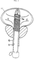
- the Foley catheter 5 with the stent prepared as above is introduced into the urethra 10 and passed into the bladder cavity 11 in such a way that the proximal portion 1 and the interspace portion 3 corresponding to the bag portion 5a enter the bladder cavity 11, as shown in Fig. 4.
- the bag portion 5a bulges out from the interspace 3 of the SMA stent.
- Accurate positioning of the SMA stent may be achieved by pulling the stent outwardly until the bulged bag portion 5a comes to abut against the bladder cervical region 11a, as shown in Fig. 5.
- the catheter 5 is deflated. After that, a flush of saline at a temperature of 41°C or above is passed through the catheter 5 to warm the SMA stent above the Af temperature.
- the stent which changes shape due to thermally induced expansion as shown in Fig. 6, is positioned at the narrowing segment 11a, 10a of the urethra 10.
- the proximal portion 1 is located at the bladder cervical region 11a and the distal portion 2 is located in the urethra 10a at the prostate.
- removal of the Foley catheter 5 leaves the stent in situ and located in the desired portion. Since the stent is in the expanded state, the catheter 5 is easily removed from within the stent.
- removal of the SMA stent is to be performed as follows.
- a Foley catheter is introduced into the retaining SMA stent.
- a flush of cold saline (below the Martensitic transforming temperature of 25°C) into the catheter cools the stent, which actuates super-elastic transformation of the stent so that the stent adopts the shape of a fine cylinder (as shown in Fig. 7) or a straightened wire, so that the stent may then be withdrawn from a body orifice.
- the stent has string attached at the end of the distal portion 2, so that the stent is readily removable by hand.
- the present invention is not limited to a urethral stent, rather the stents may be used also for the biliary or vascular system.
- Stents for use with the biliary or vascular system are typically smaller in diameter, but the diameter of the entire passage should measure about 1mm or more to ensure a blood or bile flow without an encrustation or impact, so that the stent may be retained for a longer period.
- an SMA stent For location of an SMA stent for biliary or vascular system, a guide wire and catheter is necessary. In preparation, an SMA stent is applied around the catheter 5 in the same way for the urethral stent.
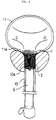
- a 0.35mm flexible tipped guide wire is inserted into a narrow segment 20a of the biliary tract or the blood vessel 20. Then the catheter which carries the SMA stent is passed over the guide wire so that the proximal portion 1 and the interspace portion 3 of the stent pass through a stricture 20a. Then in the same way as the above for the urethra stent, water is infused into the catheter, causing the bag portion 5a of the catheter 5 to bulge. The catheter 5 and stent are subsequently pulled outwardly until the stent abuts against the narrowing interior end wall 20b of the narrow segment 20a, as shown in Fig. 8. This presents the stent in the desired position.
- the catheter 5 is deflated. Subsequently saline at a temperature of from 41°C to 43°C is infused through the catheter to heat it up to approximately the same temperature. This causes the stent to expand and loosen from the catheter 5, and furthermore to retain in contact with the entire wall of mucosa. Pulling the catheter 5 from the stent leaves the stent in the right position in the biliary tract or the blood vessel.
- Removal of the SMA stent may be achieved by the same manner as the urethral stent. It is preferable that the stent has a floppy stainless steel tip at the end of the distal portion 2 to that the stent may be retrieved with a strong magnet device.
- SMA stents for a biliary, urethral and vascular system have the following advantages.
- a stent When a stent is inserted into the system, it is typically in the configuration of a contracted cylinder. This facilitates the insertion procedure. Also it allows the stent to expand to the desired shape at the Af temperature phase.
- the stent may be expanded in a simple manner by infusing saline at the Af temperature. Also the configuration at and above the Af temperature is preferably an expanded combination of a funnel portion and a cylindrical portion so that the funnel portion may contact with the narrowing interior end wall of the narrow segment and the stent is held in the right position.
- the stent By cooling with cold saline, the stent is super-elastically transformed into a fine cylinder shape or a straightened wire, thereby allowing easy removal.
- the stent of the present invention is more suitable for haemostatics after the bleeding relating to surgical intervention than any other manoeuvre such as traction with indwelled balloon catheter, since the expansion of the SMA stent allows the stent to compress directly towards the prostatic bed or the like. Indirect visceral wall compression through excessive traction at an area of bleeding inevitably causes adverse reactions.
Abstract
A stent is made of shape memory alloy which has an Austenite finished temperature (Af) ranging from 41°C to 43°C. The stent is capable of adopting a first configuration at a temperature below the Af and a second expanded configuration at or above the Af. In its first configuration the stent comprises a distal cylindrical portion (2), a proximal cylindrical portion (1), the two portions (1, 2) being connected with an interspace (3) between them. At the Af temperature the stent is reoriented, and at and above the Af temperature the proximal portion (1) flares into a funnel conical shape, expanding in maximum diameter and increasing in diameter away from the distal portion. The distal cylindrical portion (2) also expands in diameter, and the two portions directly connect with each other without the interspace (3).
Description
- This invention relates to a stent suitable for use with a biliary, urinary or vascular system. The invention concerns in particular a stent of shape memory alloy (SMA) to be placed in a pathologic stricture portion of the biliary, urinary or vascular system in the human body.
- Urethral stents made of a shape memory alloy have been developed and tested in small clinical trials. However such prior art stents have failed to provide a useful, practical treatment of prostatic obstruction.
- An example of a prior art stent is shown in Fig. 9. This comprises a
spiral coil 2 having a taperedproximal end 1 and ahinge 7 at its distal end to aid removal of the stent. (In this context, that end of the stent which is to extend furthest into the patient's body is referred to as the "proximal" end of the stent.) Another type of stent, which is not illustrated, is a cross woven cylindrical stent, which would have a diameter of 12mm, for example. - Such prior art stents would have Austenite finished temperatures (Af) of about 48°C or 36°C, respectively. Thus, the stents would transform in shape at their Af.
- In this context it is noted that the definition of Af is well known in the field of metallurgy, as are techniques for measuring it. It will be appreciated that an SMA transforms in shape at and around the Af temperature. Once it has transformed its shape, at and above the Af temperature it maintains the transformed shape. An SMA does not revert to the original shape until the temperature drops down to the Martensitic (Mf) temperature for the SMA.
- We have found that problems arise with such prior art stents. An SMA stent having an Af of 48°C must be specially designed so that it does not burn the mucosa of the human body. In fact, the mucosa of the human body will be burned at temperatures of about 43°C or above.
- In addition, we have found that an SMA stent having an Af of 36°C is liable to change its shape inadvertently. For example, it could change its shape during transportation or storage, since it would not be unusual for the temperature to rise above 36°C. In addition, the stent could perhaps be subjected to temperatures greater than 36°C in a doctor's or nurse's hand, and thus transforms its shape as it is being positioned in a patient's body and before it is in the desired location.
- Furthermore, mesh stents require the assistance of an endoscope or other special accessory tool under ultrasonic or fluoroscopic control for accurate positioning and removal.
- A stent may have to be removed for a variety of reasons, such as for example, once it has performed its function and is no longer necessary, or perhaps if it becomes encrusted, or alternatively if it migrates from its desired location such as into a bladder cavity. Thus, it can be very time consuming to use such stents. Also, they may occasionally traumatise the urethra, a blood vessel or a bile duct, which in turn may lead to bleeding or intolerable pain for patients.
- The present invention aims to alleviate at least some of the aforementioned problems associated with prior art stents.
- The present invention seeks to provide a stent which may be used in a less invasive manner, thus preferably requiring no sedation in the treatment of infravesical obstruction or the like.
- The present invention also aims to provide a stent which is readily locatable in a desired position and removable from a patient simply on an out-patient basis.
- Accordingly, in one broad aspect the present invention provides a stent made of shape memory alloy which has an Austenite finished temperature (referred in this text to as Af) ranging from about 41°C to about 43°C, the stent having a first configuration at a temperature below the Af and a second expanded configuration at or above the Af.
- Thus, in embodiments of the present invention, the stent is selected to have an Af temperature of from 41°C to 43°C so that the mucosa of a patient is not burned when the stent is used. Furthermore, the present stents are less likely to transform in shape inadvertently during transportation and storage or even when handled by a doctor, than the prior art stents.
- In embodiments of the invention the stent preferably comprises, in its first configuration, a distal cylindrical portion, a proximal cylindrical portion and an interspace therebetween. The stent adopts this first configuration at a temperature below the Af temperature. However, at the Af temperature the stent is reoriented to adopt a second, expanded configuration.
- Thus, at and above the Af temperature, in the preferred embodiment the proximal portion preferably flares into a funnel shape which increases in diameter in the direction away from the distal portion. The distal cylindrical portion also expands in diameter, in comparison with its first configuration and the two portions directly connect with each other without the interspace. In particularly preferred embodiments the distal and proximal portion are linked by a straight wire portion in the first configuration.
- In some embodiments the proximal portion and/or the distal portion of a stent are coiled. In other embodiments the proximal portion and/or the distal portion are made of mesh.
- In preferred embodiments, when the stent is in its first configuration, the proximal and distal portions of the stent are of ellipsoidal or circular cross section.
- Preferably when a stent is in its first configuration the distal portion is of longer length than the proximal portion.
- It is also preferred to include means for assisting withdrawal of a stent from a patient. For example, in preferred embodiments the stent includes a cord or similar at or near the distal end which may be pulled by a doctor to remove the stent. Alternatively, the distal end of the stent may be made of a material which is attractive to a magnet and thus the stent may be drawn out of the body with the aid of a magnet.
- In another broad aspect the present invention concerns a method of locating a stent made of a shape memory alloy having an Af ranging from about 41°C to about 43°C in a desired position in a biliary, urinary or vascular system. In this aspect, the method comprises inserting a stent in a first configuration into such a system and subsequently raising the temperature of the stent to or above its Af so that the stent assumes a second configuration.
- In preferred embodiments of this aspect of the invention the temperature of the stent is raised by contacting the stent with fluid having a temperature at or above the Af of the stent. Preferably the stent is mounted on a container for fluid, such as a catheter, and the catheter is subsequently filled with fluid of the desired temperature to cause the stent to adapt its second configuration.
- Particularly preferred embodiments involve the use of a stent which has, in its first configuration, a proximal cylindrical portion, a distal cylindrical portion and an interspace therebetween. The stent is preferably mounted on an inflatable catheter. The catheter and stent are inserted into the system and the catheter is inflated at least at or near the region of the interspace. In this way the catheter may bulge outwardly through the interspace. The catheter may be inflated by filling it with fluid at a temperature below the Af of the stent. The bulged or inflated part of the catheter may be used to assist accurate positioning of the stent. Once the stent is in a desired position the catheter is preferably drained and subsequently flushed with fluid at a temperature at or above the Af, which causes the stent to adopt its second configuration.
- A stent of the present invention may thus be placed in position as follows in a particularly preferred embodiment of the present invention.
- The stent is located around a catheter, and the catheter and stent are inserted into a biliary or urinary tract or a blood vessel in such a way that the proximal portion and the interspace portion pass through the stricture part of the tract/vessel. 2 to 5 ml of fluid such as water is passed into the catheter, causing the bag portion of the catheter to bulge or expand. The catheter with the stent located on it is then moved until the bulged bag portion abuts against the narrowed wall in the tract or blood vessel. The catheter is deflated and subsequently a flush of fluid such as saline at the Af temperature or above is fed into the catheter to reorient the stent so that it adopts its expanded configuration. The catheter is then withdrawn from the expanded stent leaving the stent in situ.
- In embodiments of the present invention, when the stent is in an expanded configuration at and above the Af temperature, the neck of the flared proximal portion fits within a narrowing part of the stricture, so that the stent is located firmly in position. Also, when locating the stent in the desired position, the catheter is readily removed from the stent because the stent has expanded in diameter.
- Embodiments of the present invention will now be described further, by way of example, with reference to the accompanying drawings in which:
- Fig. 1 is a perspective view of an example SMA urethral stent in its cold phase (Martensitic phase) configuration;
- Fig. 2 is a perspective view of a hot phase (Af) configuration of the SMA urethral stent of Fig. 1;
- Fig. 3 is an explanatory diagram showing the example SMA stent fitted around a catheter;
- Fig. 4. is an explanatory diagram showing a Foley catheter carrying an example spiral SMA urethral stent which is passed over a narrow urethra into a bladder cavity.
- Fig. 5 is an explanatory diagram showing how the SMA urethral stent of Fig. 4 is accurately positioned by inflating the catheter bag;
- Fig. 6 is an explanatory diagram showing the SMA urethral stent of Fig. 5 being left in situ at a desired position in the urethra at the prostate.
- Fig. 7 is an explanatory diagram showing how the SMA urethral stent of Fig. 6 is removed by cooling;
- Fig. 8 is an explanatory diagram showing how an example SMA stent is accurately positioned in a bilinary tract or a blood vessel by inflating a catheter bag;
- Fig. 9 is a perspective view of a conventional urethral stent.
- A urethral stent according to embodiments of the present invention is capable of adopting different configurations depending upon its temperature. An example stent made of titanium and nickel, so called Shape Memory Alloy (SMA). The transforming temperature of this SMA is in the range of from 41°C to 43°. In this text this temperature is referred to as Af (Austenite finished).
- As shown in Fig. 1, at an ambient temperature below Af, the configuration of the example SMA stent is substantially cylindrical. It includes a
distal coil portion 2, aproximal coil portion 1 and astraight wire portion 4. In this state both thecoil portions proximal coil portion 1 is short, while that of thedistal coil portion 2 is relatively long. There is aninterspace 3 between the twocoil portions straight wire portion 4 connects the twocoil portions - At an ambient temperature of and above the Af, as shown in Fig. 2, the SMA stent is reoriented to a wholly expanded coil with an anchoring
conical portion 1 tapering in diameter and a long circularcylindrical portion 2. Thewire portion 4 is absorbed into the shape combined theportions interspace 3 between the twoportions - In an example SMA urethral stent, at the Martensitic state or below the Af temperature, the
proximal coil portion 1 is, for example, about 5mm both in length and diameter, thedistal coil portion 2 is about 45mm in length and about 5mm in diameter, and the distance of theinterspace 3 is about 10mm. At the Af temperature, each respective portion of the SMA urethral stent expands in width. In this embodiment, theproximal coil portion 1 becomes 3mm in length and the flared end thereof measures 15mm in diameter. Thedistal portion 2 becomes 30mm in length and 10mm in diameter. The entire length of the stent is to be maintained at 10mm or more in diameter to secure the urinary bladder empty without any encrustation or impact, so that the stent may be retained for a longer period. - It will be appreciated that the present invention is not limited to a coiled stent, but also may be applied to a mesh stent or the like. Also other shape memory alloys with boundary temperature ranging from about 41°C to about 43°C, such as of copper and zinc, may be utilized.
- A method for insertion and removal of such an SMA urethral stent is described below.
- In preparation, as shown in Fig. 3, a tightly coiled SMA urethral stent is fitted around a
Foley catheter 5 such that theproximal portion 1 of the stent is at the insertion tip side of thecatheter 5 andinterspace 3 of the SMA stent is at a bag portion orballoon portion 5a of thecatheter 5. - To locate the stent, firstly the
Foley catheter 5 with the stent prepared as above is introduced into theurethra 10 and passed into thebladder cavity 11 in such a way that theproximal portion 1 and theinterspace portion 3 corresponding to thebag portion 5a enter thebladder cavity 11, as shown in Fig. 4. By infusing water into thecatheter 5, thebag portion 5a bulges out from theinterspace 3 of the SMA stent. Accurate positioning of the SMA stent may be achieved by pulling the stent outwardly until the bulgedbag portion 5a comes to abut against the bladdercervical region 11a, as shown in Fig. 5. - Subsequently the
catheter 5 is deflated. After that, a flush of saline at a temperature of 41°C or above is passed through thecatheter 5 to warm the SMA stent above the Af temperature. The stent, which changes shape due to thermally induced expansion as shown in Fig. 6, is positioned at the narrowingsegment urethra 10. Thus, theproximal portion 1 is located at the bladdercervical region 11a and thedistal portion 2 is located in theurethra 10a at the prostate. At this stage removal of theFoley catheter 5 leaves the stent in situ and located in the desired portion. Since the stent is in the expanded state, thecatheter 5 is easily removed from within the stent. - When the stent is no longer required or alternatively needs to be renewed, removal of the SMA stent is to be performed as follows.
- A Foley catheter is introduced into the retaining SMA stent. A flush of cold saline (below the Martensitic transforming temperature of 25°C) into the catheter cools the stent, which actuates super-elastic transformation of the stent so that the stent adopts the shape of a fine cylinder (as shown in Fig. 7) or a straightened wire, so that the stent may then be withdrawn from a body orifice. It is preferable that the stent has string attached at the end of the
distal portion 2, so that the stent is readily removable by hand. - The present invention is not limited to a urethral stent, rather the stents may be used also for the biliary or vascular system. Stents for use with the biliary or vascular system are typically smaller in diameter, but the diameter of the entire passage should measure about 1mm or more to ensure a blood or bile flow without an encrustation or impact, so that the stent may be retained for a longer period.
- For location of an SMA stent for biliary or vascular system, a guide wire and catheter is necessary. In preparation, an SMA stent is applied around the
catheter 5 in the same way for the urethral stent. - First a 0.35mm flexible tipped guide wire is inserted into a
narrow segment 20a of the biliary tract or theblood vessel 20. Then the catheter which carries the SMA stent is passed over the guide wire so that theproximal portion 1 and theinterspace portion 3 of the stent pass through astricture 20a. Then in the same way as the above for the urethra stent, water is infused into the catheter, causing thebag portion 5a of thecatheter 5 to bulge. Thecatheter 5 and stent are subsequently pulled outwardly until the stent abuts against the narrowinginterior end wall 20b of thenarrow segment 20a, as shown in Fig. 8. This presents the stent in the desired position. - After the positioning stage, the
catheter 5 is deflated. Subsequently saline at a temperature of from 41°C to 43°C is infused through the catheter to heat it up to approximately the same temperature. This causes the stent to expand and loosen from thecatheter 5, and furthermore to retain in contact with the entire wall of mucosa. Pulling thecatheter 5 from the stent leaves the stent in the right position in the biliary tract or the blood vessel. - Removal of the SMA stent may be achieved by the same manner as the urethral stent. It is preferable that the stent has a floppy stainless steel tip at the end of the
distal portion 2 to that the stent may be retrieved with a strong magnet device. - SMA stents for a biliary, urethral and vascular system according to embodiments of the present invention have the following advantages.
- When a stent is inserted into the system, it is typically in the configuration of a contracted cylinder. This facilitates the insertion procedure. Also it allows the stent to expand to the desired shape at the Af temperature phase. The stent may be expanded in a simple manner by infusing saline at the Af temperature. Also the configuration at and above the Af temperature is preferably an expanded combination of a funnel portion and a cylindrical portion so that the funnel portion may contact with the narrowing interior end wall of the narrow segment and the stent is held in the right position. By cooling with cold saline, the stent is super-elastically transformed into a fine cylinder shape or a straightened wire, thereby allowing easy removal.
- The stent of the present invention is more suitable for haemostatics after the bleeding relating to surgical intervention than any other manoeuvre such as traction with indwelled balloon catheter, since the expansion of the SMA stent allows the stent to compress directly towards the prostatic bed or the like. Indirect visceral wall compression through excessive traction at an area of bleeding inevitably causes adverse reactions.
Claims (10)
- A stent suitable for use with a biliary, urinary or vascular system, the stent being made of a shape memory alloy having an Austenite finished temperature (Af) ranging from 41°C to 43°C, the stent having a first configuration at a temperature below the Af and a second expanded configuration at or above the Af.
- A stent according to Claim 1 which comprises, in a first configuration, a distal cylindrical portion (2), a proximal cylindrical portion (1) and an interspace (3) therebetween and which is capable of adopting a second configuration in which the proximal portion (1) is flared away from the distal portion (2), the width of the proximal portion (1) is increased and the interspace (3) is reduced as compared with the first configuration.
- A stent according to Claim 1 or 2 wherein the proximal portion (1) and the distal portion (2) are coiled.
- A stent according to Claim 1 or 2 wherein the proximal portion (1) and the distal portion (2) are made of mesh.
- A stent according to any preceding claim, wherein in a first configuration the cylindrical portions (1, 2) of the stent are of ellipsoidal or circular cross section.
- A stent according to any preceding claim, wherein in a first configuration the length of the distal portion (2) is longer than that of the proximal portion (1).
- A stent according to any preceding claim, wherein in a first configuration the two portions (1, 2) are connected by a straight wire portion (4).
- A method of locating a stent as claimed in any one of the preceding claims in a desired position in a biliary, urinary or vascular system, which method comprises inserting the stent in a first configuration into a system and subsequently raising the temperature of the stent to or above its Af so that the stent assumes a second expanded configuration.
- A method according to Claim 8 in which the temperature of the stent is raised by contacting the stent with fluid having a temperature at or above the Af.
- A method according to Claim 9 which includes mounting a stent, which has in a first configuration a distal cylindrical portion, a proximal cylindrical portion and an interspace therebetween, on an inflatable catheter, inserting the catheter and stent into the system, inflating the catheter at least at or near the interspace of the stent so that the inflated catheter facilitates accurate positioning of the stent, and raising the temperature of the stent so that it assumes its second configuration.
Priority Applications (2)
| Application Number | Priority Date | Filing Date | Title |
|---|---|---|---|
| US08/190,303 US5466242A (en) | 1994-02-02 | 1994-02-02 | Stent for biliary, urinary or vascular system |
| EP94300790A EP0666065A1 (en) | 1994-02-02 | 1994-02-02 | Stent for biliary, urinary or vascular system |
Applications Claiming Priority (2)
| Application Number | Priority Date | Filing Date | Title |
|---|---|---|---|
| US08/190,303 US5466242A (en) | 1994-02-02 | 1994-02-02 | Stent for biliary, urinary or vascular system |
| EP94300790A EP0666065A1 (en) | 1994-02-02 | 1994-02-02 | Stent for biliary, urinary or vascular system |
Publications (1)
| Publication Number | Publication Date |
|---|---|
| EP0666065A1 true EP0666065A1 (en) | 1995-08-09 |
Family
ID=26136912
Family Applications (1)
| Application Number | Title | Priority Date | Filing Date |
|---|---|---|---|
| EP94300790A Withdrawn EP0666065A1 (en) | 1994-02-02 | 1994-02-02 | Stent for biliary, urinary or vascular system |
Country Status (2)
| Country | Link |
|---|---|
| US (1) | US5466242A (en) |
| EP (1) | EP0666065A1 (en) |
Cited By (18)
| Publication number | Priority date | Publication date | Assignee | Title |
|---|---|---|---|---|
| EP0778010A3 (en) * | 1995-12-07 | 1997-07-16 | Arterial Vascular Engineering, Inc. | Method and apparatus for delivery, deployment and retrieval of stents |
| FR2744625A1 (en) * | 1996-02-14 | 1997-08-14 | Bfl Sa | Thermo-expandable urethral prosthesis |
| WO1998002100A1 (en) | 1996-07-16 | 1998-01-22 | Anson Medical Limited | Surgical implants and delivery systems therefor |
| US5824037A (en) * | 1995-10-03 | 1998-10-20 | Medtronic, Inc. | Modular intraluminal prostheses construction and methods |
| EP0909199A1 (en) * | 1996-04-09 | 1999-04-21 | Endocare, Inc. | Urological stent therapy system and method |
| EP0954248A4 (en) * | 1995-10-13 | 1999-11-10 | ||
| US6110198A (en) * | 1995-10-03 | 2000-08-29 | Medtronic Inc. | Method for deploying cuff prostheses |
| US6413269B1 (en) | 2000-07-06 | 2002-07-02 | Endocare, Inc. | Stent delivery system |
| EP1239780A1 (en) * | 1999-12-23 | 2002-09-18 | Swaminathan Jayaraman | Occlusive coil manufacture and delivery |
| WO2003020173A1 (en) * | 2001-09-04 | 2003-03-13 | Graeme Cocks | A stent |
| US6629981B2 (en) | 2000-07-06 | 2003-10-07 | Endocare, Inc. | Stent delivery system |
| WO2004010909A1 (en) * | 2002-07-29 | 2004-02-05 | Eutech Medical Ab | Intra-urethral sphincter and method and means for anchoring it in a urethra |
| US6702846B2 (en) | 1996-04-09 | 2004-03-09 | Endocare, Inc. | Urological stent therapy system and method |
| EP0979059B1 (en) * | 1997-04-25 | 2004-03-10 | Boston Scientific Limited | Improved stent configurations |
| DE102006036073A1 (en) * | 2006-08-02 | 2008-02-07 | Heise, Michael, Dr.med. | Vascular tubular graft |
| US20080046064A1 (en) * | 1996-06-06 | 2008-02-21 | Jacques Sequin | Endoprosthesis deployment methods for treating vascular bifurcations |
| EP2465474A1 (en) * | 2010-12-16 | 2012-06-20 | Taewoong Medical Co., Ltd. | Urethral stent for the prostate |
| EP3453412A1 (en) * | 2017-09-08 | 2019-03-13 | Cook Medical Technologies LLC | Endovascular device configured for sequenced shape memory deployment in a body vessel |
Families Citing this family (119)
| Publication number | Priority date | Publication date | Assignee | Title |
|---|---|---|---|---|
| DE4418336A1 (en) * | 1994-05-26 | 1995-11-30 | Angiomed Ag | Stent for widening and holding open receptacles |
| US6123715A (en) | 1994-07-08 | 2000-09-26 | Amplatz; Curtis | Method of forming medical devices; intravascular occlusion devices |
| US5725552A (en) * | 1994-07-08 | 1998-03-10 | Aga Medical Corporation | Percutaneous catheter directed intravascular occlusion devices |
| US5846261A (en) * | 1994-07-08 | 1998-12-08 | Aga Medical Corp. | Percutaneous catheter directed occlusion devices |
| US5830222A (en) | 1995-10-13 | 1998-11-03 | Transvascular, Inc. | Device, system and method for intersititial transvascular intervention |
| US6616675B1 (en) * | 1996-02-02 | 2003-09-09 | Transvascular, Inc. | Methods and apparatus for connecting openings formed in adjacent blood vessels or other anatomical structures |
| US6533805B1 (en) | 1996-04-01 | 2003-03-18 | General Surgical Innovations, Inc. | Prosthesis and method for deployment within a body lumen |
| US8728143B2 (en) | 1996-06-06 | 2014-05-20 | Biosensors International Group, Ltd. | Endoprosthesis deployment system for treating vascular bifurcations |
| US6666883B1 (en) | 1996-06-06 | 2003-12-23 | Jacques Seguin | Endoprosthesis for vascular bifurcation |
| US7686846B2 (en) | 1996-06-06 | 2010-03-30 | Devax, Inc. | Bifurcation stent and method of positioning in a body lumen |
| US5843119A (en) * | 1996-10-23 | 1998-12-01 | United States Surgical Corporation | Apparatus and method for dilatation of a body lumen and delivery of a prothesis therein |
| US6258119B1 (en) * | 1996-11-07 | 2001-07-10 | Myocardial Stents, Inc. | Implant device for trans myocardial revascularization |
| US5733329A (en) * | 1996-12-30 | 1998-03-31 | Target Therapeutics, Inc. | Vaso-occlusive coil with conical end |
| US5976152A (en) * | 1997-01-28 | 1999-11-02 | Regan Stent, Inc. | Method and system for deploying shape memory prostheses with heated fluid |
| US6582472B2 (en) * | 1997-02-26 | 2003-06-24 | Applied Medical Resources Corporation | Kinetic stent |
| US6395021B1 (en) * | 1997-02-26 | 2002-05-28 | Applied Medical Resources Corporation | Ureteral stent system apparatus and method |
| US6096071A (en) * | 1998-03-26 | 2000-08-01 | Yadav; Jay S. | Ostial stent |
| US5997580A (en) * | 1997-03-27 | 1999-12-07 | Johnson & Johnson Professional, Inc. | Cement restrictor including shape memory material |
| US5980554A (en) | 1997-05-05 | 1999-11-09 | Micro Therapeutics, Inc. | Wire frame partial flow obstruction for aneurysm treatment |
| US6676682B1 (en) | 1997-05-08 | 2004-01-13 | Scimed Life Systems, Inc. | Percutaneous catheter and guidewire having filter and medical device deployment capabilities |
| US5911734A (en) | 1997-05-08 | 1999-06-15 | Embol-X, Inc. | Percutaneous catheter and guidewire having filter and medical device deployment capabilities |
| US5836966A (en) | 1997-05-22 | 1998-11-17 | Scimed Life Systems, Inc. | Variable expansion force stent |
| US6071308A (en) * | 1997-10-01 | 2000-06-06 | Boston Scientific Corporation | Flexible metal wire stent |
| US6197324B1 (en) | 1997-12-18 | 2001-03-06 | C. R. Bard, Inc. | System and methods for local delivery of an agent |
| US6251418B1 (en) | 1997-12-18 | 2001-06-26 | C.R. Bard, Inc. | Systems and methods for local delivery of an agent |
| AU1923999A (en) | 1998-01-30 | 1999-08-16 | Vascular Science Inc. | Medical graft connector or plug structures, and methods of making and installingsame |
| US5944738A (en) * | 1998-02-06 | 1999-08-31 | Aga Medical Corporation | Percutaneous catheter directed constricting occlusion device |
| US6808498B2 (en) | 1998-02-13 | 2004-10-26 | Ventrica, Inc. | Placing a guide member into a heart chamber through a coronary vessel and delivering devices for placing the coronary vessel in communication with the heart chamber |
| US6651670B2 (en) | 1998-02-13 | 2003-11-25 | Ventrica, Inc. | Delivering a conduit into a heart wall to place a coronary vessel in communication with a heart chamber and removing tissue from the vessel or heart wall to facilitate such communication |
| US20020144696A1 (en) | 1998-02-13 | 2002-10-10 | A. Adam Sharkawy | Conduits for use in placing a target vessel in fluid communication with a source of blood |
| US6689121B1 (en) | 1998-09-24 | 2004-02-10 | C. R. Bard, Inc. | Systems and methods for treating ischemia |
| US6248112B1 (en) | 1998-09-30 | 2001-06-19 | C. R. Bard, Inc. | Implant delivery system |
| US6458092B1 (en) | 1998-09-30 | 2002-10-01 | C. R. Bard, Inc. | Vascular inducing implants |
| US6432126B1 (en) | 1998-09-30 | 2002-08-13 | C.R. Bard, Inc. | Flexible vascular inducing implants |
| US6494879B2 (en) | 1998-10-15 | 2002-12-17 | Scimed Life Systems, Inc. | Treating urinary retention |
| US8092514B1 (en) | 1998-11-16 | 2012-01-10 | Boston Scientific Scimed, Inc. | Stretchable anti-buckling coiled-sheet stent |
| US6325820B1 (en) * | 1998-11-16 | 2001-12-04 | Endotex Interventional Systems, Inc. | Coiled-sheet stent-graft with exo-skeleton |
| US6692520B1 (en) | 1998-12-15 | 2004-02-17 | C. R. Bard, Inc. | Systems and methods for imbedded intramuscular implants |
| US7578828B2 (en) | 1999-01-15 | 2009-08-25 | Medtronic, Inc. | Methods and devices for placing a conduit in fluid communication with a target vessel |
| US7025773B2 (en) | 1999-01-15 | 2006-04-11 | Medtronic, Inc. | Methods and devices for placing a conduit in fluid communication with a target vessel |
| CA2360587A1 (en) | 1999-01-15 | 2000-07-20 | Darin C. Gittings | Methods and devices for forming vascular anastomoses |
| US6162238A (en) * | 1999-02-24 | 2000-12-19 | Aaron V. Kaplan | Apparatus and methods for control of body lumens |
| US6319237B1 (en) | 1999-04-23 | 2001-11-20 | Icd Labs, Inc. | Urinary sphincter control device |
| US6986784B1 (en) | 1999-05-14 | 2006-01-17 | C. R. Bard, Inc. | Implant anchor systems |
| US6855160B1 (en) | 1999-08-04 | 2005-02-15 | C. R. Bard, Inc. | Implant and agent delivery device |
| US6749606B2 (en) | 1999-08-05 | 2004-06-15 | Thomas Keast | Devices for creating collateral channels |
| US7022088B2 (en) | 1999-08-05 | 2006-04-04 | Broncus Technologies, Inc. | Devices for applying energy to tissue |
| US7175644B2 (en) | 2001-02-14 | 2007-02-13 | Broncus Technologies, Inc. | Devices and methods for maintaining collateral channels in tissue |
| US6692494B1 (en) | 1999-08-05 | 2004-02-17 | Broncus Technologies, Inc. | Methods and devices for creating collateral channels in the lungs |
| US6712812B2 (en) | 1999-08-05 | 2004-03-30 | Broncus Technologies, Inc. | Devices for creating collateral channels |
| US7815590B2 (en) | 1999-08-05 | 2010-10-19 | Broncus Technologies, Inc. | Devices for maintaining patency of surgically created channels in tissue |
| US6582441B1 (en) | 2000-02-24 | 2003-06-24 | Advanced Bionics Corporation | Surgical insertion tool |
| US6468303B1 (en) | 2000-03-27 | 2002-10-22 | Aga Medical Corporation | Retrievable self expanding shunt |
| EP1274479B1 (en) * | 2000-04-11 | 2010-07-14 | Boston Scientific Limited | Reinforced retention structures |
| US7232421B1 (en) | 2000-05-12 | 2007-06-19 | C. R. Bard, Inc. | Agent delivery systems |
| WO2001089421A2 (en) | 2000-05-22 | 2001-11-29 | Orbus Medical Technologies Inc. | Self-expanding stent |
| US7204847B1 (en) | 2000-07-28 | 2007-04-17 | C. R. Bard, Inc. | Implant anchor systems |
| IL143007A0 (en) * | 2001-05-07 | 2002-04-21 | Rafael Medical Technologies In | Retrievable intravascular support structures |
| US6494855B2 (en) | 2001-05-16 | 2002-12-17 | Scimed Life Systems, Inc. | Draining bodily fluid |
| US7338514B2 (en) | 2001-06-01 | 2008-03-04 | St. Jude Medical, Cardiology Division, Inc. | Closure devices, related delivery methods and tools, and related methods of use |
| NZ530597A (en) * | 2001-06-20 | 2006-10-27 | Park Medical Llc | Anastomotic device |
| US7115136B2 (en) | 2001-06-20 | 2006-10-03 | Park Medical Llc | Anastomotic device |
| US7708712B2 (en) | 2001-09-04 | 2010-05-04 | Broncus Technologies, Inc. | Methods and devices for maintaining patency of surgically created channels in a body organ |
| US20050060041A1 (en) * | 2001-09-04 | 2005-03-17 | Broncus Technologies, Inc. | Methods and devices for maintaining surgically created channels in a body organ |
| US8506647B2 (en) | 2002-02-14 | 2013-08-13 | Boston Scientific Scimed, Inc. | System for maintaining body canal patency |
| IL148616A (en) * | 2002-03-11 | 2008-03-20 | Oded Nahleili | Polymeric stent useful for the treatment of the salivary gland ducts |
| US8328877B2 (en) * | 2002-03-19 | 2012-12-11 | Boston Scientific Scimed, Inc. | Stent retention element and related methods |
| US7976564B2 (en) | 2002-05-06 | 2011-07-12 | St. Jude Medical, Cardiology Division, Inc. | PFO closure devices and related methods of use |
| US20040168751A1 (en) * | 2002-06-27 | 2004-09-02 | Wu Ming H. | Beta titanium compositions and methods of manufacture thereof |
| JP2005530930A (en) * | 2002-06-27 | 2005-10-13 | メムリー コーポレーション | Production method of superelastic β titanium product and product produced from the method |
| US20040261912A1 (en) * | 2003-06-27 | 2004-12-30 | Wu Ming H. | Method for manufacturing superelastic beta titanium articles and the articles derived therefrom |
| CN100387316C (en) * | 2002-09-19 | 2008-05-14 | 周星 | Meatus acusticus dilator |
| US7794494B2 (en) | 2002-10-11 | 2010-09-14 | Boston Scientific Scimed, Inc. | Implantable medical devices |
| DE60336158D1 (en) * | 2002-10-11 | 2011-04-07 | Univ Connecticut | ON SEMICRISTALLINE THERMOPLASTIC POLYURETHANES BASED FOR NANOSTRUCTURED HARD SEGMENTS BASED FORM MEMORY PILARMERS |
| US7976936B2 (en) | 2002-10-11 | 2011-07-12 | University Of Connecticut | Endoprostheses |
| DE60231843D1 (en) | 2002-11-08 | 2009-05-14 | Jacques Seguin | ENDOPROTHESIS FOR VESSEL FORKING |
| US20040267306A1 (en) | 2003-04-11 | 2004-12-30 | Velocimed, L.L.C. | Closure devices, related delivery methods, and related methods of use |
| US8372112B2 (en) | 2003-04-11 | 2013-02-12 | St. Jude Medical, Cardiology Division, Inc. | Closure devices, related delivery methods, and related methods of use |
| US7491227B2 (en) * | 2003-06-16 | 2009-02-17 | Boston Scientific Scimed, Inc. | Coiled-sheet stent with flexible mesh design |
| US8002740B2 (en) | 2003-07-18 | 2011-08-23 | Broncus Technologies, Inc. | Devices for maintaining patency of surgically created channels in tissue |
| US8308682B2 (en) | 2003-07-18 | 2012-11-13 | Broncus Medical Inc. | Devices for maintaining patency of surgically created channels in tissue |
| US20080234569A1 (en) * | 2004-01-20 | 2008-09-25 | Topspin Medical (Israel) Ltd. | Mri Probe for Prostate Imaging |
| US20050245938A1 (en) * | 2004-04-28 | 2005-11-03 | Kochan Jeffrey P | Method and apparatus for minimally invasive repair of intervertebral discs and articular joints |
| US20050267555A1 (en) * | 2004-05-28 | 2005-12-01 | Marnfeldt Goran N | Engagement tool for implantable medical devices |
| US20050278017A1 (en) * | 2004-06-09 | 2005-12-15 | Scimed Life Systems, Inc. | Overlapped stents for scaffolding, flexibility and MRI compatibility |
| US8409167B2 (en) | 2004-07-19 | 2013-04-02 | Broncus Medical Inc | Devices for delivering substances through an extra-anatomic opening created in an airway |
| US20060084866A1 (en) * | 2004-10-18 | 2006-04-20 | Gadi Lewkonya | Expanding imaging probe |
| US20060084861A1 (en) * | 2004-10-18 | 2006-04-20 | Topspin Medical (Isreal) Ltd. | Magnet and coil configurations for MRI probes |
| US7455688B2 (en) | 2004-11-12 | 2008-11-25 | Con Interventional Systems, Inc. | Ostial stent |
| US8043361B2 (en) * | 2004-12-10 | 2011-10-25 | Boston Scientific Scimed, Inc. | Implantable medical devices, and methods of delivering the same |
| DE102006013770A1 (en) * | 2006-03-24 | 2007-09-27 | Occlutech Gmbh | Occlusion instrument and method for its production |
| US20080051879A1 (en) * | 2006-08-23 | 2008-02-28 | Cook Incorporated | Methods of treating venous valve related conditions with a flow-modifying implantable medical device |
| ATE499912T1 (en) * | 2006-12-04 | 2011-03-15 | Cook Inc | METHOD FOR INSERTING A MEDICAL DEVICE INTO A RELEASE SYSTEM |
| WO2008092013A1 (en) * | 2007-01-26 | 2008-07-31 | Wilson-Cook Medical Inc. | Implantable drainage device with planar dual curved portion |
| US20100130815A1 (en) * | 2007-05-18 | 2010-05-27 | Prostaplant Ltd. | Intraurethral and extraurethral apparatus |
| US8034061B2 (en) | 2007-07-12 | 2011-10-11 | Aga Medical Corporation | Percutaneous catheter directed intravascular occlusion devices |
| US8361138B2 (en) * | 2007-07-25 | 2013-01-29 | Aga Medical Corporation | Braided occlusion device having repeating expanded volume segments separated by articulation segments |
| US20090112251A1 (en) * | 2007-07-25 | 2009-04-30 | Aga Medical Corporation | Braided occlusion device having repeating expanded volume segments separated by articulation segments |
| US20090082803A1 (en) | 2007-09-26 | 2009-03-26 | Aga Medical Corporation | Braided vascular devices having no end clamps |
| US8066715B2 (en) * | 2007-10-03 | 2011-11-29 | Cook Medical Technologies Llc | Magnetic stent removal |
| US20090143760A1 (en) * | 2007-11-30 | 2009-06-04 | Jacques Van Dam | Methods, Devices, Kits and Systems for Defunctionalizing the Gallbladder |
| WO2009131689A1 (en) * | 2008-04-23 | 2009-10-29 | Cook Incorporated | Method of loading a medical device into a delivery system |
| WO2010077966A1 (en) | 2008-12-17 | 2010-07-08 | Abbott Laboratories Vascular Enterprises Limited | Methods and apparatus for filtering a body lumen |
| US8905961B2 (en) * | 2008-12-19 | 2014-12-09 | St. Jude Medical, Inc. | Systems, apparatuses, and methods for cardiovascular conduits and connectors |
| US9901347B2 (en) | 2009-05-29 | 2018-02-27 | Terus Medical, Inc. | Biliary shunts, delivery systems, and methods of using the same |
| US20100312203A1 (en) * | 2009-06-04 | 2010-12-09 | Colorado Catheter Company, Inc. | Tear Away Fluid Collection Container |
| EP2361594A4 (en) * | 2009-07-10 | 2014-11-05 | Taewoong Medical Co Ltd | Stent |
| US20110087252A1 (en) | 2009-10-08 | 2011-04-14 | Wilson-Cook Medical Inc. | Biliary decompression and anastomosis stent |
| WO2011143174A1 (en) | 2010-05-10 | 2011-11-17 | Aguirre Andres F | Device for external percutaneous connections |
| US8709034B2 (en) | 2011-05-13 | 2014-04-29 | Broncus Medical Inc. | Methods and devices for diagnosing, monitoring, or treating medical conditions through an opening through an airway wall |
| JP2014521381A (en) | 2011-05-13 | 2014-08-28 | ブロンカス テクノロジーズ, インコーポレイテッド | Methods and devices for tissue ablation |
| US8465551B1 (en) * | 2011-07-09 | 2013-06-18 | Bandula Wijay | Temporary prostatic stent for benign prostatic hyperplasia |
| WO2013078235A1 (en) | 2011-11-23 | 2013-05-30 | Broncus Medical Inc | Methods and devices for diagnosing, monitoring, or treating medical conditions through an opening through an airway wall |
| CN106456182B (en) | 2013-12-20 | 2021-04-09 | 泰尔茂株式会社 | Vascular occlusion device |
| US20180353278A1 (en) * | 2015-11-05 | 2018-12-13 | Swedish Health Services | Prosthetic phrenoesophageal membrane |
| US11197750B2 (en) | 2016-11-29 | 2021-12-14 | Lake Region Manufacturing, Inc. | Embolic protection device |
| CN110267627B (en) | 2016-12-09 | 2023-07-11 | 真复灵公司 | Systems, devices, and methods for accurately deploying implants in the prostatic urethra |
| WO2020093012A1 (en) | 2018-11-01 | 2020-05-07 | Terumo Corporation | Occlusion systems |
| JP2023502997A (en) | 2019-11-19 | 2023-01-26 | ゼンフロー, インコーポレイテッド | Systems, devices and methods for accurate deployment and imaging of implants within the prostatic urethra |
Citations (9)
| Publication number | Priority date | Publication date | Assignee | Title |
|---|---|---|---|---|
| WO1989001798A1 (en) * | 1987-09-02 | 1989-03-09 | Engineers & Doctors A/S | Device for the placing of a partial catheter in a body cavity |
| EP0380668A1 (en) * | 1987-10-08 | 1990-08-08 | Terumo Kabushiki Kaisha | Instrument and apparatus for securing inner diameter of lumen of tubular organ |
| EP0418381A1 (en) * | 1987-09-21 | 1991-03-27 | Terumo Kabushiki Kaisha | Ureter redressing device |
| WO1991016005A1 (en) * | 1990-04-19 | 1991-10-31 | Stentek Inc. | Device for the treatment of constricted vessels |
| FR2661603A1 (en) * | 1990-05-02 | 1991-11-08 | Coralines Abj Division Sarl | Prosthesis for treating stenoses in the channels of the body |
| WO1992005747A1 (en) * | 1990-10-09 | 1992-04-16 | Moskovsky Institut Stali I Splavov | Appliance for implantation in hollow organs and device for its introduction |
| EP0481365A1 (en) * | 1990-10-13 | 1992-04-22 | Angiomed Ag | Device for expanding a stenosis in a body duct |
| WO1992019310A1 (en) * | 1991-04-26 | 1992-11-12 | Advanced Coronary Technology, Inc. | Removable heat-recoverable tissue supporting device |
| WO1993013824A1 (en) * | 1992-01-20 | 1993-07-22 | Engineers & Doctors A/S | Segmentarily expandable tubular endoluminal prosthesis |
Family Cites Families (7)
| Publication number | Priority date | Publication date | Assignee | Title |
|---|---|---|---|---|
| US4503569A (en) * | 1983-03-03 | 1985-03-12 | Dotter Charles T | Transluminally placed expandable graft prosthesis |
| US5067957A (en) * | 1983-10-14 | 1991-11-26 | Raychem Corporation | Method of inserting medical devices incorporating SIM alloy elements |
| US4665908A (en) * | 1985-06-11 | 1987-05-19 | Calkin Carston R | Extrication and spinal restraint device |
| JPS63238872A (en) * | 1987-03-25 | 1988-10-04 | テルモ株式会社 | Instrument for securing inner diameter of cavity of tubular organ and catheter equipped therewith |
| US4795458A (en) * | 1987-07-02 | 1989-01-03 | Regan Barrie F | Stent for use following balloon angioplasty |
| US5242451A (en) * | 1987-09-24 | 1993-09-07 | Terumo Kabushiki Kaisha | Instrument for retaining inner diameter of tubular organ lumen |
| US5231989A (en) * | 1991-02-15 | 1993-08-03 | Raychem Corporation | Steerable cannula |
-
1994
- 1994-02-02 EP EP94300790A patent/EP0666065A1/en not_active Withdrawn
- 1994-02-02 US US08/190,303 patent/US5466242A/en not_active Expired - Fee Related
Patent Citations (9)
| Publication number | Priority date | Publication date | Assignee | Title |
|---|---|---|---|---|
| WO1989001798A1 (en) * | 1987-09-02 | 1989-03-09 | Engineers & Doctors A/S | Device for the placing of a partial catheter in a body cavity |
| EP0418381A1 (en) * | 1987-09-21 | 1991-03-27 | Terumo Kabushiki Kaisha | Ureter redressing device |
| EP0380668A1 (en) * | 1987-10-08 | 1990-08-08 | Terumo Kabushiki Kaisha | Instrument and apparatus for securing inner diameter of lumen of tubular organ |
| WO1991016005A1 (en) * | 1990-04-19 | 1991-10-31 | Stentek Inc. | Device for the treatment of constricted vessels |
| FR2661603A1 (en) * | 1990-05-02 | 1991-11-08 | Coralines Abj Division Sarl | Prosthesis for treating stenoses in the channels of the body |
| WO1992005747A1 (en) * | 1990-10-09 | 1992-04-16 | Moskovsky Institut Stali I Splavov | Appliance for implantation in hollow organs and device for its introduction |
| EP0481365A1 (en) * | 1990-10-13 | 1992-04-22 | Angiomed Ag | Device for expanding a stenosis in a body duct |
| WO1992019310A1 (en) * | 1991-04-26 | 1992-11-12 | Advanced Coronary Technology, Inc. | Removable heat-recoverable tissue supporting device |
| WO1993013824A1 (en) * | 1992-01-20 | 1993-07-22 | Engineers & Doctors A/S | Segmentarily expandable tubular endoluminal prosthesis |
Non-Patent Citations (1)
| Title |
|---|
| DATABASE WPI Section PQ Week 9345, 5 January 1994 Derwent World Patents Index; Class P, AN 93-358282 * |
Cited By (30)
| Publication number | Priority date | Publication date | Assignee | Title |
|---|---|---|---|---|
| US6110198A (en) * | 1995-10-03 | 2000-08-29 | Medtronic Inc. | Method for deploying cuff prostheses |
| US6193745B1 (en) | 1995-10-03 | 2001-02-27 | Medtronic, Inc. | Modular intraluminal prosteheses construction and methods |
| US6123722A (en) * | 1995-10-03 | 2000-09-26 | Medtronics, Inc. | Stitched stent grafts and methods for their fabrication |
| US5824037A (en) * | 1995-10-03 | 1998-10-20 | Medtronic, Inc. | Modular intraluminal prostheses construction and methods |
| EP0954248A4 (en) * | 1995-10-13 | 1999-11-10 | ||
| US7059330B1 (en) | 1995-10-13 | 2006-06-13 | Medtronic Vascular, Inc. | Methods and apparatus for bypassing arterial obstructions and/or performing other transvascular procedures |
| EP0954248A1 (en) * | 1995-10-13 | 1999-11-10 | Transvascular, Inc. | Methods and apparatus for bypassing arterial obstructions and/or performing other transvascular procedures |
| EP1166721A3 (en) * | 1995-10-13 | 2003-12-03 | Transvascular, Inc. | Apparatus for transvascular procedures |
| US7134438B2 (en) | 1995-10-13 | 2006-11-14 | Medtronic Vascular, Inc. | Methods and apparatus for bypassing arterial obstructions and/or performing other transvascular procedures |
| EP0778010A3 (en) * | 1995-12-07 | 1997-07-16 | Arterial Vascular Engineering, Inc. | Method and apparatus for delivery, deployment and retrieval of stents |
| US6579305B1 (en) | 1995-12-07 | 2003-06-17 | Medtronic Ave, Inc. | Method and apparatus for delivery deployment and retrieval of a stent comprising shape-memory material |
| FR2744625A1 (en) * | 1996-02-14 | 1997-08-14 | Bfl Sa | Thermo-expandable urethral prosthesis |
| EP0909199A1 (en) * | 1996-04-09 | 1999-04-21 | Endocare, Inc. | Urological stent therapy system and method |
| US6702846B2 (en) | 1996-04-09 | 2004-03-09 | Endocare, Inc. | Urological stent therapy system and method |
| EP0909199A4 (en) * | 1996-04-09 | 2001-02-21 | Endocare Inc | Urological stent therapy system and method |
| US6416545B1 (en) | 1996-04-09 | 2002-07-09 | Endocare, Inc. | Urological stent therapy system and method |
| US8603157B2 (en) * | 1996-06-06 | 2013-12-10 | Biosensors International Group, Ltd. | Endoprosthesis deployment methods for treating vascular bifurcations |
| US20080046064A1 (en) * | 1996-06-06 | 2008-02-21 | Jacques Sequin | Endoprosthesis deployment methods for treating vascular bifurcations |
| WO1998002100A1 (en) | 1996-07-16 | 1998-01-22 | Anson Medical Limited | Surgical implants and delivery systems therefor |
| EP0979059B1 (en) * | 1997-04-25 | 2004-03-10 | Boston Scientific Limited | Improved stent configurations |
| EP1239780A4 (en) * | 1999-12-23 | 2006-05-03 | Swaminathan Jayaraman | Occlusive coil manufacture and delivery |
| EP1239780A1 (en) * | 1999-12-23 | 2002-09-18 | Swaminathan Jayaraman | Occlusive coil manufacture and delivery |
| US6629981B2 (en) | 2000-07-06 | 2003-10-07 | Endocare, Inc. | Stent delivery system |
| US6413269B1 (en) | 2000-07-06 | 2002-07-02 | Endocare, Inc. | Stent delivery system |
| WO2003020173A1 (en) * | 2001-09-04 | 2003-03-13 | Graeme Cocks | A stent |
| WO2004010909A1 (en) * | 2002-07-29 | 2004-02-05 | Eutech Medical Ab | Intra-urethral sphincter and method and means for anchoring it in a urethra |
| DE102006036073A1 (en) * | 2006-08-02 | 2008-02-07 | Heise, Michael, Dr.med. | Vascular tubular graft |
| EP2465474A1 (en) * | 2010-12-16 | 2012-06-20 | Taewoong Medical Co., Ltd. | Urethral stent for the prostate |
| EP3453412A1 (en) * | 2017-09-08 | 2019-03-13 | Cook Medical Technologies LLC | Endovascular device configured for sequenced shape memory deployment in a body vessel |
| US10596016B2 (en) | 2017-09-08 | 2020-03-24 | Cook Medical Technologies Llc | Endovascular device configured for sequenced shape memory deployment in a body vessel |
Also Published As
| Publication number | Publication date |
|---|---|
| US5466242A (en) | 1995-11-14 |
Similar Documents
| Publication | Publication Date | Title |
|---|---|---|
| EP0666065A1 (en) | Stent for biliary, urinary or vascular system | |
| US5667522A (en) | Urological stent and deployment device therefor | |
| US20090210045A1 (en) | Stent | |
| US8177741B2 (en) | Catheter with superelastic retention device | |
| US6780175B1 (en) | Medical instrument with slotted memory metal tube | |
| EP1951150B1 (en) | Stent with anchoring portion | |
| US7691078B2 (en) | Draining bodily fluids with a stent | |
| US7258696B2 (en) | Apparatus for delivering, repositioning and/or retrieving self-expanding stents | |
| JPH0351430B2 (en) | ||
| JP2006504487A (en) | Linearly expandable ureteral stent | |
| WO2002083195A2 (en) | Device for aiding urination and method of use thereof | |
| JPS63160644A (en) | Living body pipeline dilator | |
| JP3214733B2 (en) | Urethral stent | |
| JPH02289240A (en) | Device for ensuring bore of tubular organ lumen and organ lumen holding catheter incorporating the same device | |
| MXPA96003872A (en) | Urological restraint apparatus and device device for im |
Legal Events
| Date | Code | Title | Description |
|---|---|---|---|
| PUAI | Public reference made under article 153(3) epc to a published international application that has entered the european phase |
Free format text: ORIGINAL CODE: 0009012 |
|
| AK | Designated contracting states |
Kind code of ref document: A1 Designated state(s): DE FR GB |
|
| STAA | Information on the status of an ep patent application or granted ep patent |
Free format text: STATUS: THE APPLICATION IS DEEMED TO BE WITHDRAWN |
|
| 18D | Application deemed to be withdrawn |
Effective date: 19960210 |