EP0666556A2 - Sound field controller and control method - Google Patents
Sound field controller and control method Download PDFInfo
- Publication number
- EP0666556A2 EP0666556A2 EP95101466A EP95101466A EP0666556A2 EP 0666556 A2 EP0666556 A2 EP 0666556A2 EP 95101466 A EP95101466 A EP 95101466A EP 95101466 A EP95101466 A EP 95101466A EP 0666556 A2 EP0666556 A2 EP 0666556A2
- Authority
- EP
- European Patent Office
- Prior art keywords
- sound
- signal
- reflection
- listener
- loudspeaker
- Prior art date
- Legal status (The legal status is an assumption and is not a legal conclusion. Google has not performed a legal analysis and makes no representation as to the accuracy of the status listed.)
- Granted
Links
Images


Classifications
-
- G—PHYSICS
- G10—MUSICAL INSTRUMENTS; ACOUSTICS
- G10K—SOUND-PRODUCING DEVICES; METHODS OR DEVICES FOR PROTECTING AGAINST, OR FOR DAMPING, NOISE OR OTHER ACOUSTIC WAVES IN GENERAL; ACOUSTICS NOT OTHERWISE PROVIDED FOR
- G10K15/00—Acoustics not otherwise provided for
- G10K15/02—Synthesis of acoustic waves
Landscapes
- Health & Medical Sciences (AREA)
- Audiology, Speech & Language Pathology (AREA)
- General Health & Medical Sciences (AREA)
- Physics & Mathematics (AREA)
- Engineering & Computer Science (AREA)
- Acoustics & Sound (AREA)
- Multimedia (AREA)
- Stereophonic System (AREA)
Abstract
Description
- The present invention relates to a sound field controller for use in audio-visual (AV) equipment, and a method used in such a sound field controller. More particularly, the present invention relates to a sound field controller for sound reproduction with a sense of presence by controlling the distance perspective and the sense of expansion of a sound image, and with superior reproduction frequency characteristics.
- In recent years, as VTRs (video tape recorders) have become a common household item, a large-screened display and a sound reproduction system giving a sense of presence are desired to enjoy music as well as movies on video tapes at home, thereby giving rise to the requirement of corresponding hardware development.
- Figure 41 shows an example of a conventional
sound field controller 400 which controls the distance perspective. As shown in Figure 41, thesound field controller 400 includes asignal input device 401 for inputting an audio signal, again controller 402, a pair ofamplifiers loudspeakers distance input device 404. Thedistance input device 404 is connected to thegain controller 402. Signal levels in two channels are changed depending on the distance by thedistance input device 404, so as to control the distance perspective for the sound image which is received by a listener. - The conventional
sound field controller 400 having the above-described construction will be described below. - A signal input through the
signal input device 401 is applied to thegain controller 402. Thegain controller 402 controls the level of the input signal so that the input signal can be reproduced from theloudspeakers distance input device 404. In general, as the sound volume of a signal to be reproduced is increased, the position of the sound source is felt to be nearer. On the other hand, as the sound volume is decreased, the position of the sound source is felt to be farther. According to thesound field controller 400, thegain controller 402 controls the sound volume of the reproduced signal, so that the distance perspective from the sound source which is felt by the listener is controlled. The signal having a level which is controlled by thegain controller 402 is amplified by theamplifiers loudspeakers - However, in the conventional
sound field controller 400 having the above-described construction, the distance perspective is controlled using a direct sound only. Accordingly, even if the listener listens to the reproduced sound at a suitable position, the listener has a strange feeling that the reproduced distances are different from the actual distances. Moreover, thesound field controller 400 can give a proper distance perspective in the forward direction to the listener, but cannot realize a proper distance perspective in the backward and side directions. - An exemplary sound reproducing apparatus includes a loudspeaker system in which a horn or a sound tube for guiding a sound wave generated from a diaphragm is provided in a front face portion of the loudspeaker diaphragm. An example of such a
loudspeaker system 450 is shown in Figures 42A and 42B. - Figures 42A and 42B are cross-sectional views showing the main portions of the structure of the
loudspeaker system 450 used in the conventional sound reproducing apparatus. Figure 42A shows a transverse cross section, and Figure 42B shows a vertical cross section. As shown in Figures 42A and 42B, aloudspeaker unit 451 is attached at an opening of aback cavity 452. Theback cavity 452 prevents a sound wave emitted from a back face of a diaphragm of theloudspeaker unit 451 from leaking out of theloudspeaker unit 451. Ahorn 453 is mounted on theback cavity 452 so that thehorn 453 is positioned in front of theloudspeaker unit 451. As shown in Figure 42A, thehorn 453 has a conical shape. Specifically, a transverse cross-sectional area of thehorn 453 increases from the front face of the diaphragm of theloudspeaker unit 451 toward an opening 453a. As shown in Figure 42B, a vertical cross-sectional area of thehorn 453 decreases toward the opening 453a. The sound wave generated by the diaphragm of theloudspeaker unit 451 is emitted to the outside through asound path portion 454, as a sound. - If the length L of the
horn 453 is set to be sufficiently larger than the wavelength of the frequency band of the reproduced sound, the variation of acoustic impedance at the opening 453a becomes very small. Thus, superior matching can be attained for the acoustic impedance at the opening 453a. In such a case, the frequency characteristic of the reproduced sound pressure is flat, and an ideal loudspeaker system can be realized. - However, if such a
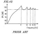
loudspeaker system 450 is incorporated in AV equipment such as a television image receiver (hereinafter, referred to as a television set or a TV), it is actually impossible to set the length of thehorn 453 to be sufficiently larger than the wavelength of the frequency band of the reproduced sound. Therefore, the reproduced sound pressure frequency characteristic of the general loudspeaker system using a horn includes a large number of peak dips, as shown in Figure 43. This is because the acoustic impedance is drastically changed at the opening 453a, so that part of the sound wave emitted from theloudspeaker unit 451 is reflected from the opening 453a, and hence a resonance occurs in thesound path portion 454. The resonance causes a large number of peaks. - In a loudspeaker system having a sound tube having a substantially uniform cross-sectional area instead of the
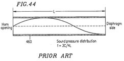
horn 453, this resonance also occurs, and hence a large number of peaks are caused in the reproduced sound pressure frequency characteristic. For example, the case where asound tube 460 as shown in Figure 44 is used is described. When the length of thesound tube 460 is denoted by L, and the sound velocity is denoted by C, the resonance occurs at the frequency which is denoted by f and represented as follows:
f = (2n-1) C / 4L (n = 1, 2, 3, ...)
Figure 44 shows the sound pressure distribution in the case of n = 2. - Figure 45 shows a
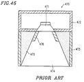
loudspeaker system 470 using an absorbing material in order to realize a flat reproduced frequency characteristic with less peak dips (see for example, Japanese Patent Application No. 63-109343). Theloudspeaker system 470 reduces the number of peaks by disposing anabsorber 475 and apartition plate 476 on the side face of thesound path portion 474. However, in the case where the absorbing characteristic of theabsorber 475 is not uniform, or in the case where a sufficient amount ofabsorber 475 is not disposed because of the shape of the loudspeaker system, theloudspeaker system 470 has a drawback in that the desired characteristic cannot be always obtained. - The sound field controller of this invention for reproducing a sound field provides a distance perspective depending on a position of a sound image for a listener. The sound field controller includes: an A/D converter for converting an input audio signal into a digital signal; a signal processing section for receiving the digital signal, processing the digital signal using predetermined parameters, and generating a sound signal; an input device for inputting conditions which include a position of a sound image to be localized and a distance from a listener; a parameter controller for setting the parameters in the signal processing section so that the sound signal has characteristics in accordance with the conditions; a D/A converter for converting the sound signal output from the signal processing section into an analog signal; and a reproduction reflection generator amplifying and reproducing the analog signal output from the D/A converter.
- In one embodiment of the invention, the signal processing section includes: a direct sound processing section for receiving the digital signal and generating a direct sound signal by which a sound image of a direct sound is localized in a direction toward a sound source; a reflection sound processing section including a delay circuit for receiving the digital signal and delaying the digital signal in accordance with a reflection time of a reflection sound, and a reflection generator for generating a reflection sound signal by which a sound image of the reflection sound is localized in a direction in which the reflection sound is reflected; and an adder for adding the direct sound signal to the reflection sound signal.
- In another embodiment of the invention, the reflection generator for generating a reflection sound signal includes a filter unit, and the parameter controller sets a delay time in the delay circuit and filter coefficients for the filter unit, based on the position of the sound image and the distance from the listener.
- In another embodiment of the invention, the signal processing section further includes a summation ratio controller for continuously changing ratios of the direct sound signal and the reflection sound signal to be added.
- In another embodiment of the invention, the signal processing section further includes a reverberation sound generator for adding a reverberation sound to a signal output from the adder, the conditions input from the input device further includes an expansion of a sound field, and the parameter controller sets a parameter for the reverberation sound generator based on the expansion of the sound field.
- In another embodiment of the invention, the conditions input from the input device includes the position of the sound image, the distance from the listener, and an expansion of a sound field, and the signal processing section includes: a direct sound processing section for receiving the digital signal and generating a direct sound signal by which a sound image of a direct sound is localized in a direction toward a sound source; a reflection sound processing section including a delay circuit for receiving the digital signal and delaying the digital signal in accordance with a reflection time of a reflection sound, and a reflection generator for generating a reflection sound signal by which a sound image of the reflection sound is localized in a direction in which the reflection sound is reflected; a summation ratio controller for adding the direct sound signal to the reflection sound signal by continuously changing summation ratios thereof, and outputting a sum signal; and a reverberation sound generator for adding a reverberation sound to the sum signal output from the summation ratio controller.
- In another embodiment of the invention, the signal processing section includes a frequency characteristic controller for changing frequency characteristics of the direct sound signal and the reflection sound signal.
- In another embodiment of the invention, the input device is parameter receiving unit for receiving sound field control signals supplied from the outside of the sound field controller.
- In another embodiment of the invention, the signal processing section includes: a direct sound processing section for receiving the digital signal and generating a direct sound signal; a reflection sound processing section including a plurality of delay circuit for receiving and delaying the digital signal in accordance with respective reflection times of a plurality of reflection sounds and generating a plurality of delay signals, and gain controller for outputting reflection sound signals by adjusting respective gains for the delay signals; and an adder for adding the direct sound signal to the reflection sound signals.
- In another embodiment of the invention, the conditions include a side reflection angle which is formed by a direction of a reflection sound which reaches the listener after being emitted from a sound source and then reflected from a wall of an audio space with respect to a direction from the sound source to the listener, and the parameter controller converts the side reflection angle into a parameter of a position of a listener and/or a parameter of a position of a sound image, and inputs the parameter into the signal processing section.
- According to another aspect of the invention, a sound reproducing apparatus in which a signal from a sound signal source is processed by a signal processing section, and the processed sound signal is reproduced from loudspeaker systems is provided. In the apparatus, each of the loudspeaker systems includes a horn for guiding a sound wave emitted from a front face of a diaphragm of a loudspeaker unit, and has a resonance frequency due to the horn, and the signal processing section includes a filter unit for receiving the signal, attenuating the resonance frequency components of the signal in a frequency band of a sound to be reproduced, and outputting a resulting sound signal.
- According to another aspect of the invention, a sound reproducing apparatus in which a signal from a sound signal source is processed by a signal processing section, and the processed sound signal is reproduced from a loudspeaker system and rear loudspeakers, respectively, is provided. In the apparatus, the loudspeaker system includes loudspeaker units located on front left and front right sides of a listener, and horns for guiding sound waves emitted from front faces of diaphragms of the loudspeaker units, the loudspeaker system having a resonance frequency due to the horns, the rear loudspeakers are located on rear left and rear right sides of the listener, and the signal processing section includes a generator for generating a surround signal from the signals, and a filter unit for receiving the signal, attenuating the resonance frequency components of the signal in a frequency band of a sound to be reproduced, and outputting a resulting sound signal.
- In one embodiment of the invention, the loudspeaker systems are located on front left and front right sides of a listener, and the signal processing section further includes a sound field control section for receiving the sound signal, converting the sound signal so that a sound image of the sound signal is localized at a desired position, and outputting the converted signal to the loudspeaker systems.
- According to another aspect of the invention, a sound reproducing apparatus in which a signal from a sound signal source is processed by a signal processing section, and the processed sound signal is reproduced from a loudspeaker system and effect loudspeakers, respectively, is provided. In the apparatus, the loudspeaker system includes loudspeaker units located on front left and front right sides of a listener, and horns for guiding sound waves emitted from front faces of diaphragms of the loudspeaker units, the loudspeaker system having a resonance frequency caused by the horns, the effect loudspeakers are located on the outer left and right sides of the loudspeaker system, the effect loudspeakers reproducing an expansion sound, and the signal processing section includes a filter unit for receiving the signal, attenuating the resonance frequency components of the signal in a frequency band of a sound to be reproduced, and outputting a resulting sound signal to the loudspeaker system and the effect loudspeakers.
- In one embodiment of the invention, the loudspeaker systems are located on front left and front right sides of a listener, and the signal processing section further includes a sound image expanding section for receiving the sound signal, converting the received sound signal so that a sound image of the sound signal is localized on front left and front right sides of the listener, and on outer left and right sides thereof, and outputting the converted signal to the loudspeaker systems, whereby an expanded sound including a moving sound is reproduced from the loudspeaker systems.
- In another embodiment of the invention, the loudspeaker systems are located on front left and front right sides of a listener, and the signal processing section further includes a speech conversion section for receiving the sound signal, converting, when the received sound signal is judged to be a speech signal, a reproducing velocity of the speech signal, and outputting the speech signal to the loudspeaker systems.
- In another embodiment of the invention, the loudspeaker systems are located on front left and front right sides of a listener, and the signal processing section includes: a speech detector for receiving the sound signal, judging whether the sound signal is a speech signal or a non-speech signal, and outputting the speech signal and the non-speech signal separately from each other; a sound field control section for receiving the non-speech signal, converting the non-speech signal so that a sound image of the non-speech signal is localized at a desired position, and outputting the converted signal; and an adder for receiving and adding the converted signal and the speech signal to each other, and outputting the added signal to the loudspeaker systems.
- In another embodiment of the invention, the filter unit reduces a gain of the sound signal at the resonance frequency, so that a sound pressure of a reproduced sound at the resonance frequency of the loudspeaker systems is equal to or lower than a predetermined level.
- In another embodiment of the invention, the loudspeaker systems are provided on side faces of a cathode-ray tube of a television image receiver, respectively.
- In another embodiment of the invention, a cross-sectional area of the horn is increased from the front face of the diaphragm of the loudspeaker unit toward an opening from which the sound wave is emitted.
- In another embodiment of the invention, a cross-sectional area of the horn is substantially uniform from the front face of the diaphragm of the loudspeaker unit toward an opening from which the sound wave is emitted.
- According to another aspect of the invention, a sound field control method for reproducing a sound field which provides a distance perspective depending on a position of a sound image for a listener is provided. The method includes the steps of: converting an input audio signal into a digital signal; processing the digital signal using predetermined parameters, and generating a sound signal; setting conditions which include a position of a sound image to be localized and a distance from a listener; controlling the parameters used in the signal processing step so that the sound signal has characteristics in accordance with the conditions; converting the sound signal into an analog signal; and amplifying and reproducing the analog signal.
- In one embodiment of the invention, the signal processing step includes the steps of: processing the digital signal so as to generate a direct sound signal for localizing a sound image of a direct sound in a direction toward a sound source; delaying the digital signal in accordance with a reflection time of a reflection sound, and processing the delayed digital signal so as to generate a reflection sound signal for localizing a sound image of the reflection sound in a direction in which the reflection sound is reflected; and adding the direct sound signal and the reflection sound signal.
- In another embodiment of the invention, the step of generating a reflection sound signal includes a filtering step, and the step of controlling the parameters includes a step of setting a delay time of the digital signal and a step of setting filter coefficients for the filtering step, based on the position of the sound image and the distance from the listener.
- In another embodiment of the invention, the signal processing step further includes a step of continuously changing summation ratios of the direct sound signal and the reflection sound signal to be added.
- In another embodiment of the invention, the signal processing step further includes a step of adding a reverberation sound to a sum signal generated in the adding step, the conditions further includes an expansion of a sound field, and the parameter control step further includes a step of setting a parameter for the step of adding a reverberation sound based on the expansion of the sound field.
- In another embodiment of the invention, the conditions includes the position of the sound image, the distance from the listener, and an expansion of a sound field, and the signal processing step includes the steps of: processing the digital signal so as to generate a direct sound signal for localizing a sound image of a direct sound in a direction toward a sound source; delaying the digital signal in accordance with a reflection time of a reflection sound, and processing the delayed digital signal so as to generate a reflection sound signal for localizing a sound image of the reflection sound in a direction in which the reflection sound is reflected; adding the direct sound signal and the reflection sound signal by continuously changing summation ratios thereof, and outputting a sum signal; and adding a reverberation sound signal to the sum signal in accordance with the expansion of the sound field.
- In another embodiment of the invention, the signal processing step further includes a step of controlling frequency characteristics of the direct sound signal and the reflection sound signal.
- In another embodiment of the invention, the signal processing step further includes a step of continuously changing summation ratios of the direct sound signal and the reflection sound signal to be added.
- In another embodiment of the invention, the step of setting the conditions includes a step of receiving sound field control signals supplied from the outside of the sound field controller and a step of determining conditions based on the control signals.
- In another embodiment of the invention, the signal processing step includes the steps of: processing the digital signal so as to generate a direct sound signal; delaying the digital signal in accordance with respective reflection times of a plurality of reflection sounds, generating a plurality of delay signals, and adjusting respective gains for the delay signals so as to generate reflection sound signals; and adding the direct sound signal and the reflection sound signals.
- In another embodiment of the invention, the conditions include a side reflection angle which is formed by a direction of a reflection sound which reaches the listener after being emitted from a sound source and then reflected from a wall of an audio space with respect to a direction from the sound source to the listener, and in the step of controlling the parameters, the side reflection angle is converted into a parameter of a position of a listener and/or a parameter of a position of a sound image.
- According to another aspect of the invention, a sound reproducing method including the steps of processing a signal from a sound signal source, and reproducing the processed sound signal from loudspeaker systems, each of the loudspeaker systems including a horn for guiding a sound wave emitted from a front face of a diaphragm of a loudspeaker unit, and each of the loudspeaker systems having a resonance frequency due to the horn is provided. In the method, the processing step includes a filtering step of receiving the signal, attenuating the resonance frequency components of the signal in a frequency band of a sound to be reproduced, and outputting a resulting sound signal.
- In one embodiment of the invention, the loudspeaker systems are located on front left and front right sides of a listener, and the processing step further includes a sound field control step for converting the sound signal so that a sound image of the sound signal is localized at a desired position, and outputting the converted signal to the loudspeaker systems.
- In another embodiment of the invention, the loudspeaker systems are located on front left and front right sides of a listener, and the signal processing step further includes a sound image expansion step of converting the received sound signal so that a sound image of the sound signal is localized on front left and front right sides of the listener, and on outer left and right sides thereof, and outputting the converted signal to the loudspeaker systems, whereby an expanded sound including a moving sound is reproduced from the loudspeaker systems.
- In another embodiment of the invention, the loudspeaker systems are located on front left and front right sides of a listener, and the signal processing step further includes a speech conversion step of converting, when the sound signal is judged to be a speech signal, a reproducing velocity of the speech signal, and outputting the speech signal to the loudspeaker systems.
- In another embodiment of the invention, the loudspeaker systems are located on front left and front right sides of a listener, and the signal processing step includes: a step of judging whether the sound signal is a speech signal or a non-speech signal, and outputting the speech signal and the non-speech signal separately from each other; a sound field control step of converting the non-speech signal so that a sound image of the non-speech signal is localized at a desired position, and outputting the converted signal; and a step of adding the converted signal and the speech signal to each other, and outputting the added signal to the loudspeaker systems.
- In another embodiment of the invention, in the filtering step, a gain of the sound signal at the resonance frequency is reduced, so that a sound pressure of a reproduced sound at the resonance frequency of the loudspeaker systems is equal to or lower than a predetermined level.
- Thus, the invention described herein makes possible the advantages of (1) providing a sound field controller and a sound field control method by which natural distance perspective and sense of expansion in all directions can be given, (2) providing a sound field controller which can reproduce a sound with high clarity without deteriorating the sound characteristics, while it is unnecessary to increase the length of a horn or a sound tube (hereinafter collectively referred to as a horn) of a loudspeaker system and it is unnecessary to dispose an absorber and a partition plate, and (3) providing a sound field controller which can clearly reproduce a speech signal and reproduce a sound with a sense of presence and natural expansion and which can be produced with a simple system construction at a low cost.
- These and other advantages of the present invention will become apparent to those skilled in the art upon reading and understanding the following detailed description with reference to the accompanying figures.
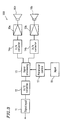
- Figure 1 is a block diagram for illustrating a principle of sound localization in a sound field controller according to the invention.
- Figure 2 is a diagram illustrating the construction of an operation circuit of the sound field controller according to the invention.
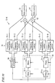
- Figure 3 is a block diagram of a sound field controller in Example 1 according to the invention.
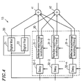
- Figure 4 is a block diagram showing an exemplary signal processing section in the sound field controller according to the invention.
- Figure 5 is a diagram showing the relationship between a reflection sound and a direct sound.
- Figure 6A is a graph showing the relationship between a level of a reflection sound and a time.
- Figure 6B is a graph showing the relationship between the level of a reverberation sound and a time.
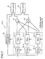
- Figure 7 is a block diagram showing a signal processing section in a sound field controller in Example 2 according to the invention.
- Figure 8 is a block diagram showing a signal processing section in a sound field controller in Example 3 according to the invention.
- Figure 9 is a block diagram showing a signal processing section in a sound field controller in Example 4 according to the invention.
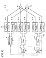
- Figure 10 is a block diagram showing a signal processing section in a sound field controller in Example 5 according to the invention.
- Figure 11 is a block diagram showing a signal processing section in a sound field controller in Example 6 according to the invention.
- Figure 12 is a block diagram showing a sound field controller in Example 7 according to the invention.
- Figure 13 is a block diagram showing a signal processing section in a sound field controller in Example 8 according to the invention.
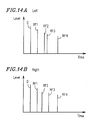
- Figures 14A and 14B are graphs showing the relationships between a sound level of a reflection sound and a delay time in the sound field controller in Example 8.
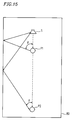
- Figure 15 is a diagram for illustrating the concept of parameter control in a sound field controller according to the invention.
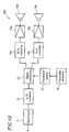
- Figure 16 is a block diagram schematically showing the construction of a sound field controller in Example 9 according to the invention.
- Figure 17 is a graph showing a frequency characteristic of the loudspeaker system in Example 9.
- Figure 18 is a graph showing a frequency characteristic of a filter used in the examples according to the invention.
- Figure 19 is a graph showing a reproduce sound pressure frequency characteristic in the examples according to the invention.
- Figure 20 is a diagram showing the construction of a sound reproducing apparatus in Example 10 according to the invention.
- Figure 21 is a diagram schematically showing the construction of a sound reproducing apparatus in Example 11 according to the invention.
- Figure 22 is a block diagram showing the construction of a signal processing section in a sound reproducing apparatus in Example 12 according to the invention.
- Figure 23 is a block diagram showing the construction of a sound processing section in a sound reproducing apparatus in Example 13 according to the invention.
- Figure 24 is a diagram schematically showing the construction of a sound reproducing apparatus in Example 14 according to the invention.
- Figure 25 is a diagram schematically showing the construction of a sound reproducing apparatus in Example 15 according to the invention.
- Figure 26 is a diagram showing a specific example of a sound image expanding section in Example 15.
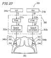
- Figure 27 is a diagram schematically showing a sound reproducing apparatus in Example 16 according to the invention.
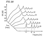
- Figure 28 is a graph showing an accumulated spectrum of a frequency characteristic (the falling characteristic) of a loudspeaker system including a horn.
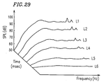
- Figure 29 is a graph showing an accumulated spectrum of a reproduced sound pressure frequency characteristic (the falling characteristic) in Example 16.
- Figure 30 is a diagram schematically showing a sound reproducing apparatus in Example 17 according to the invention.
- Figure 31 is a block diagram showing the construction of a signal processing section in Example 18 according to the invention.
- Figure 32 is an example of a waveform of a speech signal.
- Figure 33 is a block diagram showing the construction of a signal processing section in Example 19 according to the invention.
- Figure 34 is a block diagram showing the construction of a signal processing section in Example 20 according to the invention.
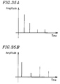
- Figures 35A and 35B are diagrams schematically showing the reflection sound series generated by a reflection sound generation circuit in Example 20.
- Figures 36A and 36B are block diagrams for explaining the reflection sound generation circuits in Example 20.
- Figure 37 is a block diagram showing the construction of a signal processing section in Example 21 according to the invention.
- Figure 38 is a block diagram showing the construction of a signal processing section in Example 22 according to the invention.
- Figure 39 is a block diagram showing the construction of a signal processing section in Example 23 according to the invention.
- Figure 40 is a block diagram showing the construction of a signal processing section in Example 24 according to the invention.
- Figure 41 is a block diagram showing a conventional sound field controller which controls the distance perspective.
- Figures 42A and 42B are a transverse cross-sectional view and a vertical cross-sectional view, respectively, showing a loudspeaker system used in sound reproducing apparatus of the prior art and the invention.
- Figure 43 is a diagram showing a frequency characteristic of a reproduced sound pressure in a conventional sound reproducing apparatus.
- Figure 44 is a diagram for illustrating the sound pressure distribution in a sound tube used in a loudspeaker system.
- Figure 45 is a cross-sectional view showing another construction of a loudspeaker system used in a conventional sound reproducing apparatus.
- First, a method for virtually localizing the sound image in an arbitrary direction will be explained with reference to Figure 1. Figure 1 shows a diagram indicating the principle of virtually generating a sound image localization using a left-channel (Lch)
loudspeaker 4 and a right-channel (Rch)loudspeaker 3, which is equivalent to the sound image localization generated from the signal reproduced from a left-side loudspeaker 5. In Figure 1, theloudspeakers listener 6. An input signal S(t) is applied tooperational circuits operational circuit 1 comprises an FIR filter for performing convolution with impulse response hLR(n), and theoperational circuit 2 comprises an FIR filter for performing convolution with impulse response hLL(n). In this figure, h1(t) represents the impulse response at the left-ear position (more accurately, the position of the eardrum, or in the case of measurement, the entrance of the acoustic meatus) of thelistener 6 when theloudspeaker 4 produces an impulse sound. Hereinafter, the term "impulse response" is used for the description in a time domain, and the term "head-related transfer function" is used for the description in a frequency domain. Similarly, h2(t) represents the impulse response at the right-ear position of thelistener 6 when theloudspeaker 4 produces the impulse sound. Also, h3(t) represents the impulse response at the left-ear position of thelistener 6 when theloudspeaker 3 produces an impulse sound, h4(t) represents the impulse response at the right-ear position of thelistener 6 when theloudspeaker 3 produces the impulse sound, h5(t) represents the impulse response at the left-ear position of thelistener 6 when theloudspeaker 5 produces the impulse sound, and h6(t) represents the impulse response at the right-ear position of thelistener 6 when theloudspeaker 5 produces the impulse sound. - In this configuration, when the signal S(t) is produced from the
loudspeaker 5, the sound that reaches the ears of thelistener 6 is expressed by the following equations. - Specifically, the sound pressure L(t) at the left ear is represented by Equation (1).

- The sound pressure R(t) at the right ear is expressed as

where * represents a convolution. - A transfer function of the loudspeaker itself which is multiplied in practical situations is ignored in the case under consideration. Alternatively, the transfer function of the loudspeakers may be considered to be included in the impulse response functions.
- Further, supposing that the sound pressures L(t) and R(t) given by Equations (1) and (2), the impulse responses h1(t) to h6(t), and the signal S(t) are all temporally discrete digital signals, they are converted to the formations as shown by the following expressions (3), (4), (5), (6) and (7).


- In this case, Equations (1) and (2) are expressed by following Equations (8) and (9) respectively.


- It should be noted that the natural number n should actually be expressed by nT instead, T indicating a sampling time. However, T is omitted as usual and Equations (8) and (9) are written in the above-mentioned expression.
- Similarly, when the signal S(t) is reproduced from the
loudspeakers listener 6 is represented by following Equations (10) and (11). The sound pressure at the left ear is given by Equation (10).
- The sound pressure at the right ear is expressed by Equation (11).

- Assuming that the sounds are perceived as coming from the same direction if the head related transfer functions of the sounds are equivalent to each other (i.e., the direction from which sound is coming is determined based on the amplitude difference and the time difference between the sounds reaching the right and left ears, and this assumption is generally valid), Equations (12) to (15) hold as follows.


- Thus, the impulse responses hLL(n) and hLR(n) may be determined so as to satisfy Equations (13) and (15).
- The impulse responses h1(t) to h6(t) and hLL(t) to hLR(t) are rewritten in a frequency domain expression as shown by following Equations (16) to (23).


where FFT( ) represents a function transformed by Fourier transformation (FFT: Fast Fourier Transformer). - Next, Equations (13) and (15) are also rewritten in the frequency domain expression. The operation is transformed from a convolution to a multiplication as represented in Equations (24) and (25). The remaining parts are transformed to the transfer functions with the respective impulse responses by Fourier transformation.


- In Equations (24) and (25), the values other than the transfer functions HLL(n) and HLR(n) are obtained by measurement. Therefore, the transfer functions HLL(n) and HLR(n) can be obtained from following Equations (26) and (27).


- By using hLL(n) and hLR(n) obtained from HLL(n) and HLR(n) by performing the inverse Fourier transformation (IFFT), and applying the signal S(n) to the
operational circuits loudspeaker 4 is obtained by performing the convolution with S(n) and hLL(n), and the signal to be produced from theloudspeaker 3 is obtained by preforming the convolution with S(n) and hLR(n). When the convolution sum signals are reproduced and the corresponding sounds are output from therespective loudspeakers listener 6 can perceive the sounds as if the sound comes from theleft loudspeaker 6 that is not actually played. - The method described above can virtually localize the sound image in a desirable direction.
- An exemplary structure of an FIR filter for performing convolution is shown in Figure 2. In Figure 2, the signal is applied to a
signal input terminal 10a and goes through serially connected N-1delay elements 7. Each ofdelay elements 7 delays the signal by τ, each of themultipliers 8 multiplies the input signal by a value called the tap (a coefficient of the FIR filter) indicated by h(n), an adder 9 adds all the signals output from themultipliers 8, and the added (sum) signal is output via anoutput terminal 10b. Although the FIR filter shown in Figure 2 is formed by hardware, the FIR filter may be implemented by using a DSP (Digital Signal Processor) or a custom LSI for high speed multiplication and addition operations. - The impulse responses h(n) (n: 0 to N-1, where N is the required length of the impulse response) are set up as the tap coefficients of the
respective multipliers 8 as shown in Figure 2. Also, a delay time corresponding to the sampling frequency of converting an analog signal to a digital signal is set up in each of thedelay elements 7. The signals applied to theinput terminal 10a are multiplied/added/delayed repeatedly, thereby the convolution as shown in Equations (8) and (9) is performed. This operation involves digital signals. In practice, therefore, an A/D converter and a D/A converter are to be provided in order to convert analog signals to digital signals before being applied to the FIR filter, and to convert the digital signal output from the FIR filter to an analog signal (these converters are not shown in the figures as is the case in the following descriptions). - The impulse response hLL(t) and hLR(t) are obtained in the above mentioned manner, and the sound image is localized on the left side or left rear by using the
operational circuits - Similarly, when the sound image is to be localized on the right side or right rear, hRL(t) and hRR(t) are obtained so as to perform the convolution.
- Next, the present invention will be described by way of Example 1. Figure 3 is a block diagram showing the whole construction of a
sound field controller 100 in Example 1 according to the invention. As shown in Figure 3, thesound field controller 100 includes asignal input device 11 for inputting an audio signal, an A/D converter 12, asignal processing section 13, a pair of D/A converters amplifiers loudspeakers parameter controller 17, and aninput device 18. - Through the
input device 18, the position of a listener, the position at which the sound image is to be localized, the distance between the listener and the sound image, and the spatial size of the sound field are input. The output of theinput device 18 is fed to theparameter controller 17. Theparameter controller 17 controls the parameter which is set in thesignal processing section 13, based on the conditions such as the positions, the distance, and the spatial size of the sound field which are fed from theinput device 18. Theparameter controller 17 previously stores convolution coefficients for localizing the sound image in any direction and at any positions with respect to the listener. Theparameter controller 17 selects a value satisfying the input conditions among them, and sets the value in thesignal processing section 13. - Figure 4 is a block diagram showing the construction of the
signal processing section 13 in Example 1, in detail. Thesignal processing section 13 includes a directsound processing section 20 for localizing the sound image of a direct sound, and a reflectionsound processing section 30 for localizing the sound image of a reflection sound. As shown in Figure 4, the output from the A/D converter 12 is input into the directsound processing section 20 and the reflectionsound processing section 30. - The direct
sound processing section 20 includes a pair ofdigital filters - The reflection
sound processing section 30 includes a plurality of filter portions 31-1 to 31-n and a plurality of delay circuits 32-1 to 32-n, and localizes the reflection sound images at positions corresponding to the reflecting positions of the first to n-th reflection sounds. Each of the delay circuits 32-1 to 32-n delays a signal for localizing a corresponding reflection sound, in accordance with the delay time set by theparameter controller 17. The outputs of the delay circuits 32-1 to 32-n are input to the filter portions 32-1 to 32-n, respectively. Each of the filter portions 32-1 to 32-n includes a pair of digital filters. As filter coefficients of the digital filters, the convolution coefficients corresponding to the positions of the sound images which are output from theparameter controller 17 are set. By setting the filter coefficients in accordance with the attenuation level output from theparameter controller 17, the signal for localizing the reflection sound is attenuated. In this way, a natural distance perspective in accordance with the input conditions can be supplied for the listener. - The number n of the filter portions and the delay circuits is determined on the basis of the positions at which the reflection sound images are to be localized. The digital filters used in the direct
sound processing section 20 and the reflectionsound processing section 30 have the same construction as that of the digital filter shown in Figure 2. The right and left outputs from the respective filter portions 32-k (k = 1 to n) of the reflectionsound processing section 30 are applied toadders adder 41 adds the right sound signals to each other, and theadder 42 adds the left sound signals to each other. The outputs of theadders A converters - Next, the operation of the sound field controller in this example will be described. First, an audio signal is input into the
signal input device 11. The input audio signal is converted into a digital signal by the A/D converter 12, and then applied to thesignal processing section 13. For the signal input into thesignal processing section 13, the sound image of the direct sound is localized by the directsound processing section 20 and the sound images of the respective reflection sounds are localized by the reflectionsound processing section 30. - From the
input device 18, the positions of the listener and the sound image, the distance between them, the spatial size of the sound field, and the like are input. Theparameter controller 17 sets the parameters used in thesignal processing section 13 in order to obtain the characteristics in accordance with the conditions input through theinput device 18, so as to control the directions of reflection sounds, the sound volume, the reverberation time, the frequency characteristic, and the position and the magnitude of the sound image of the direct sound. The respective right and left outputs from the directsound processing section 20 and the reflectionsound processing section 30 are added, and the added results are output from thesignal processing section 13 as right and left signals. The signals processed by thesignal processing section 13 are converted into analog signals by the D/A converters amplifiers loudspeakers - Next, the parameter control in the
signal processing section 13 will be described. As shown in Figure 5, in the case where thelistener 6 listens to a sound in a sound field, it is assumed that the number of directions of reflection sounds for a direct sound D is four. These reflection sounds are referred to as RF1, RF2, RF3, and RF4 numbered in the order that they reach the ears of thelistener 6. The relationship between the time and the four reflection sounds are, for example, shown in Figure 6. In accordance with the positional relationship between thelistener 6 and the sound image, the following factors are changed: the volume valance between the direct sound D and the initial reflection sound RF1; the time period after the direct sound D occurs until the initial reflection sound RF1 occurs; and the level balances and the time intervals between the reflection sounds RF1 to RF4. By combining them, thelistener 6 can psychologically feel the distance and expansion. - For example, in the case where there are four reflection sounds as shown in Figure 6, the delay times and attenuation levels of the respective reflection sounds for the direct sound D are set as follows by means of the
input device 18. - Initial reflection sound RF1:
Delay time 5.5 ms,Level 80% - Reflection sound RF2:
Delay time 7.3 ms, Level 77% - Reflection sound RF3:
Delay time 7.9 ms, Level 76% - Reflection sound RF4:
Delay time 17.4 ms,Level 50% - In accordance with these values, the delay time for each delay circuit 32-k (k = 1 to 4) in the reflection
sound processing section 20 is set by theparameter controller 17. Each of the delayed signals is input into a corresponding one of the filter portions 31-k (k = 1 to 4). Theparameter controller 17 sets the coefficients of the filter portions 31-k (k = 1 to 4), so as to realize the direction of each reflection sound in the reflection sound series which are previously stored depending on the distances of the sound image. As a result, as described above, the positions of the sound images of the direct sound and each reflection sound are implemented by convolution operation by the digital filter, so that the sound image can be localized in a desired direction. - Figure 7 shows a signal processing section 13-2 of the sound field controller in Example 2. The sound field controller in Example 2 has the same construction as that of the
sound field controller 100 in Example 1 shown in Figure 3 except for the construction of thesignal processing section 13. Components which are the same as those described in Example 1 are designated by the same reference numerals, and the detailed descriptions thereof are omitted. The signal processing section 13-2 further includes direct sound to reflectionsound ratio controllers signal processing section 13. - In the signal processing section 13-2, only the respective outputs of the reflection
sound processing section 30 is added to each other in theadders sound processing section 20 and the output signal of theadder 41 are input into the direct sound to reflectionsound ratio controller 51. The direct sound to reflectionsound ratio controller 51 controls the ratio of the direct sound to the reflection sound in the left channel. Similarly, the other output signal of the directsound processing section 20 and the output signal of theadder 42 are input into the direct sound to reflectionsound ratio controller 52. The direct sound to reflectionsound ratio controller 52 controls the ratio of the direct sound to the reflection sound in the right channel. - The direct sound to reflection
sound ratio controller 51 adds the signal input from the directsound processing section 20 to the signal input from the reflectionsound processing section 30 via theadder 41, while the output ratio is continuously varied. Accordingly, the continuous variation of the distance perspective can be attained. For example, in the case where the distance perspective up to about l m is desired, the ratio of the direct sound to the reflection sound is set to be 50 : 50. In the case where the distance perspective up to about 2 to 5 m is desired, the ratio of the direct sound to the reflection sound is set to be 30 : 70. - Figure 8 shows a signal processing section 13-3 of a sound field controller in Example 3. The sound field controller in Example 3 has the same construction as that of the
sound field controller 100 in Example 1 shown in Figure 3 except for the construction of thesignal processing section 13. Like components to those described in Example 1 are designated by like reference numerals, and the detailed descriptions thereof are omitted. The signal processing section 13-3 further includesreverberation sound generators signal processing section 13. - The
reverberation sound generators adders reverberation sound generators - Figure 9 shows the signal processing section 13-4 of a sound field controller in Example 4. The sound field controller in Example 4 has the same construction as that of the
sound field controller 100 in Example 1 shown in Figure 3 except for the construction of thesignal processing section 13. Like components to those described in the above-described examples are designated by like reference numerals, and the detailed descriptions thereof are omitted. The signal processing section 13-4 further includesreverberation sound generators - Figure 10 shows a signal processing section 13-5 of a sound field controller in Example 5. The sound field controller of Example 5 has the same construction as that of the
sound field controller 100 in Example 1 shown in Figure 3 except for the construction of thesignal processing section 13. Like components to those described in the above-described examples are designated by like reference numerals, and the detailed descriptions thereof are omitted. The signal processing section 13-5 further includes a frequencycharacteristic controller 70, in addition to the components of thesignal processing section 13 in Example 1. - As shown in Figure 10, the frequency
characteristic controller 70 includes portions 70-1 to 70-(2n+2) corresponding to the outputs from the directsound processing section 20 and the reflectionsound processing section 30, respectively. The frequencycharacteristic controller 70 controls the sound pressure characteristics of the input signals. For example, the sound is reflected by a wall of a room, various attenuation ratios occur depending on the frequency components of the sound. Therefore, in the case where the distance between the listener and the sound image is long, the distance perspective can be attained by lowering the sound pressure of the higher frequency range than that of the lower frequency range. In order to attain the distance perspective of 5 to 10 m, the frequency characteristics are controlled as follows, for example, after the addition of reflection sound.
Frequency : 4 kHz, Gain : +5 dB (1/3 oct)
Frequency : 8 kHz, Gain : +5 dB (1/3 oct) - The output signals from the frequency
characteristic controller 70 are added by theadders A converters - Figure 11 shows a signal processing section 13-6 of a sound field controller in Example 6. The sound field controller of Example 6 has the same construction as that of the
sound field controller 100 in Example 1 shown in Figure 3 except for the construction of thesignal processing section 13. Like components to those described in the above-described examples are designated by like reference numerals, and the detailed descriptions thereof are omitted. The signal processing section 13-6 further includes direct sound to reflectionsound ratio controllers sound processing section 30 are processed by the frequency characteristic controller 70 (70-3 to 70-(2n+2)), and then added by theadders sound ratio controllers sound processing section 20 are respectively input into the direct sound to reflectionsound ratio controllers - Figure 12 shows a
sound field controller 200 in Example 7 according to the invention. Like components of thesound field controller 200 in Example 7 to those of thesound field controller 100 described in Example 1 shown in Figure 3 are designated by like reference numerals, and the detailed descriptions thereof are omitted. Thesound field controller 200 includes aparameter receiving device 19 for receiving a control signal for controlling the distance perspective between the listener and the sound image and the sense of expansion of the sound field from the outside of thesound field controller 200. - The
parameter receiving device 19 is coupled to external control equipment (not shown). Theparameter receiving device 19 receives control signals including the conditions such as the distance perspective and the sense of expansion, for example, a parameter control signal for an audio signal synchronized with a video signal and a control signal which is previously programmed. Based on the received control signals, theparameter controller 17 sets the parameters for thesignal processing section 13. The operation thereafter is the same as that described in the above-described examples. - As described above, in this example, the distance perspective and sense of expansion can be controlled by the external control signals. By using the previously programmed signals, the control can be performed repeatedly, and the combination with a video signal, and the distance perspective and sense of expansion depending on the scene of the video screen can be controlled.
- Alternatively, instead of the
reproduction loudspeakers - Figure 13 shows a signal processing section 13-8 of a sound field controller in Example 8. The sound field controller in Example 8 has the same construction as that of the
sound field controller 100 in Example 1 shown in Figure 3 except for the construction of thesignal processing section 13. Like components to those in the above-described examples are designated by like reference numerals, and the detailed descriptions thereof are omitted. In the signal processing section 13-8, the convolution in the filter portions 31-k of the reflectionsound processing section 30 is omitted. The signal processing section 13-8 provides the distance perspective with a more simplified circuit configuration. As shown in Figure 13, the signal processing section 13-8 has no filter portions, and hence the convolution for localizing the sound image at a virtual position of a loudspeaker is not performed. Instead, the distance perspective is attained by using the difference between times at which the reflection sounds are received by the right and left ears of the listener and the difference between levels of the received reflection sounds. - The signal processing section 13-8 shown in Figure 13 shows a signal processing circuit for one of either the right channel or the left channel. A signal processing circuit for the other channel is identical with that shown in Figure 13, and hence the description thereof is omitted. The reflection
sound processing section 30 includes delay circuits 32-1 to 32-n for delaying an input signal, and gain controllers 33-1 to 33-n for adjusting the amplitudes of the output signals of the delay circuits 32-1 to 32-n. Theadder 41 adds the output of the directsound processing section 20 which is not delayed to the outputs of the gain controllers 331-to 33-n. - Specific examples of the gain control will be described below. For example, it is assumed that the right and left ears of the listener receive four reflection sounds, respectively. The case where the distance perspective of about 5 m is provided by there reflection sounds is considered. Examples of the left and right reflection sounds set by the
input device 18 are shown in Figures 14A and 14B, respectively. The delay times and attenuation levels of the respective reflection sounds for the direct sound D to the left ear shown in Figure 14A are set as follows. - Reflection sound RF1 : Delay time 5.5 ms,
Level 80% - Reflection sound RF2 : Delay time 7.3 ms, Level 77%
- Reflection sound RF3 : Delay time 7.9 ms, Level 76%
- Reflection sound RF4 : Delay time 17.4 ms,
Level 50% - Similarly, the delay times and attenuation levels of the respective reflection sounds for the direct sound D to the right ear shown in Figure 14B are set as follows.
- Reflection sound RF1 : Delay time 5.5 ms,
Level 80% - Reflection sound RF2 : Delay time 7.1 ms, Level 77%
- Reflection sound RF3 : Delay time 8.1 ms, Level 76%
- Reflection sound RF4 : Delay time 17.4 ms,
Level 50% - In accordance with these values, the delay time for each delay circuit 32-k and the gain for each gain controller 33-k are set.
- By the
input device 18 shown in Figure 3, the spatial size of the sound field, and the position of the sound source are input, and hence the parameters for thesignal processing section 13 are controlled. Figure 15 is a diagram for illustrating an example of parameter control in the sound field controller in the above example. As shown in Figure 15, it is assumed that, in aroom 80, a sound generated from a sound source S is listened to by a listener P (P1 or P2). At this time, the distance between the listener P and the sound image (sound source) S is represented by a side reflection angle ϑ. For example, for the listener P2 who is far from the sound image (sound source) S, the value of ϑ is small. For the listener P1 who is positioned near the sound image S, the value of ϑ is large. In this way, by using the side reflection angle ϑ as a parameter, the distance from the sound image S can be represented. Depending on the value of ϑ output from theinput device 18, the delay times and the convolution coefficients in thesignal processing section 13 are controlled. - Figure 16 is a block diagram schematically showing the construction of a
sound field controller 300 according to Example 9. Example 9 implements a sound field controller having a reproduced sound pressure frequency characteristic with less peak dips, considering the resonance phenomenon of the loudspeaker system. - As shown in Figure 16, sound signals SL and SR from an L-channel (Lch)
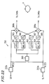
signal source 310a and a R-channel (Rch)signal source 310b are input intofilters signal processing section 320, respectively. Sound signals SL' and SR' processed in thesignal processing section 320 are reproduced fromloudspeaker systems loudspeaker systems loudspeaker unit 332, aback cavity 333, and ahorn 334. - Each of the
filters filters loudspeaker systems filters - Figure 17 shows the reproduced sound pressure frequency characteristic in the case where the sound is reproduced by one
loudspeaker system 330a (or oneloudspeaker system 330b, hereinafter collectively referred to as a loudspeaker system 330) including thehorn 334 without filters. Similar to the characteristic in the conventional loudspeaker system which has been described, peaks occur at resonance frequencies f1, f2, ... caused by a standing wave generated in accordance with the length of thehorn 334. - Figure 18 is a graph showing the frequency characteristic of the
filter 321a (or 321b, hereinafter collectively referred to as a filter 321). This graph shows the output signal (SL' or SR') from the filter 321 of thesignal processing section 320, when a sound signal having a frequency band of audible sound is output from thesignal source 310a (or 310b) and processed by the corresponding filter 321. As shown in Figure 18, the filter 321 reduces the gain of the signal to a desired level at the resonance frequencies f1, f2, ... of the loudspeaker system 330. - The output signal of the
signal processing section 320 is input into the loudspeaker system 330. The loudspeaker system 330 has the pressure frequency characteristic as shown in Figure 17, so that the emitted sound reproduced from the loudspeaker system 330 has the output frequency characteristic shown in Figure 19. The influence of the standing wave by thehorn 334 is eliminated in the output frequency characteristic, so that a sound with high clarity can be obtained. - In this example, the filter 321 is constituted by a BIQUAD 3-stage serial connection type IIR filter. The gains supplied to the IIR filter are determined based on differences between the peak levels in the frequency characteristic of the loudspeaker system 330 and the desired output sound pressure levels at the resonance frequencies f1, f2, and f3 of the
horn 334, so as to realize the dips at the respective resonance frequencies shown in Figure 18 (in one channel). In this example, the peaks at the resonance frequencies f1 to f3 are removed. Alternatively, by increasing the number of stages of the IIR filter, the peaks at higher-order resonance frequencies can be removed. The manner for establishing the gains is not limited to the above-described specific one. The desired characteristic can alternatively be attained by a certain gain. In this example, the IIR filter is constituted by a digital filter using a DSP. Alternatively, the IIR filter may be an analog filter. In this example, the Lch and Rch signals from the stereophonic source are used. It is appreciated that if a monophonic signal is used, the same effects can be attained. - Next, a
sound reproducing apparatus 301 in Example 10 according to the invention will be described with reference to the figures. Figure 20 shows the construction of thesound reproducing apparatus 301 used in a television system. As shown in Figure 20, the television system includesloudspeaker systems ray tube 345. Theloudspeaker systems ray tube 345, so that the shapes of aback cavity 343 and ahorn 344 provided for aloudspeaker unit 342 are different from those of theback cavity 333 and thehorn 334 shown in Figure 16. - In an audio room for watching and listening to the television,
rear loudspeakers rear loudspeakers - The signals from the
Lch signal source 310a and theRch signal source 310b are input intofilters signal processing section 320, respectively. Thesefilters filters loudspeaker systems filter 322a is applied to theloudspeaker system 340a and the output of thefilter 322b is applied to theloudspeaker system 340b. - In the
sound reproducing apparatus 301 having the above-described construction, the sound output from theloudspeaker system 340a reaches a listener P via the path of the transfer function CLM, and the sound output from theloudspeaker system 340b reaches the listener P via the path of the transfer function CRM. The signals of the surround sounds generated by thesignal processing section 320 are reproduced from therear loudspeakers sound reproducing apparatus 301, sounds with high clarity and flat frequency characteristics are output from thefront loudspeaker systems rear loudspeakers - The
sound reproducing apparatus 301 shown in Figure 20 requires therear loudspeakers - A
sound reproducing apparatus 302 in Example 11 according to the invention negates the above problems. Figure 21 is a diagram schematically showing the construction of thesound reproducing apparatus 302. Components which are the same as those in thesound reproducing apparatus 301 shown in Figure 20 are designated by the same reference numerals, and the descriptions thereof are omitted. - A
signal processing section 350 of thesound reproducing apparatus 302 includesfilters field control sections field control sections loudspeaker systems field control sections filters field control sections front loudspeaker systems field control section 351a is set to be (1+CLS/CLM), and the transfer function HR of the soundfield control section 351b is set to be (1+CRS/CRM). - The operation of the
sound reproducing apparatus 302 having the above-described construction will be described. For the frequency characteristics of thefilters loudspeaker systems signal source 310a is processed by thefilter 322a, so as to generate a signal SL' in which the gains at the resonance frequencies of thehorn 344 are reduced. The signal SL' is input into the soundfield control section 351a, and multiplied by the transfer function HL = (1+CLS/CLM). Thus, a signal of SL'·(1+CLS/CLM) is output (the symbol "·" indicates the multiplication). - The signal SL'·(1+CLS/CLM) is input into the
loudspeaker system 340a, and sound transformed by theloudspeaker unit 342. The frequency characteristic of thehorn 344 is the same as that shown in Figure 17, so that the sound wave emitted from thehorn 344 is SL·(1+CLS/CLM). When the sound wave reaches the ears of the listener via the sound path of the transfer function CLM, the sound wave becomes SL·(1+CLS/CLM)·CLM = SL·(CLM+CLS). This value is equal to the synthetic sound of thefront loudspeaker system 340a and therear loudspeaker 311a shown in Figure 20. Thus, the surrounding effect which is the same as that attained by thesound reproducing apparatus 301 in Example 10 can be attained. In the above description, the Lch signal SL is described. It is appreciated that the same description can be made for the Rch signal SR. - As described above, the Lch and Rch signals are listened to as coming from directions which are indicated by broken lines in Figure 21 (i.e., from virtual loudspeakers), so that rear loudspeakers for reproducing surround sounds are not required.
- As for the signals of stereophonic source, the frequency components of the standing wave depending on the lengths of the horns 344a and 344b are reduced by the
filters field control sections - Next, the
signal processing section 350 in the sound reproducing apparatus in Example 12 will be described. The sound reproducing apparatus has the same construction as that of thesound reproducing apparatus 302 shown in Figure 21, except for the construction of thesignal processing section 350. Figure 22 is a block diagram showing the construction of thesignal processing section 350 in Example 12. In Figure 22, an output signal SL' from thefilter 322a and an output signal SR' from thefilter 322b are each divided into two branches. One of the branched signals of SL' and one of the branched signals of SR' are applied to adifference signal extractor 360 and the others toadders difference signal extractor 360 calculates the difference between the two signals applied thereto, and outputs the difference signal tooperational circuits - Each of the
operational circuits operational circuits - In other words, the
operational circuit 361 has an impulse response hRR(n), theoperational circuit 362 an impulse response hRL(n), theoperational circuit 363 an impulse response hLR(n), and theoperational circuit 364 an impulse response hLL(n). The output of theoperational circuit 361 is applied to theadder 369b via adelay circuit 365, the output of theoperational circuit 362 to theadder 369a via adelay circuit 366, the output of theoperational circuitry 363 to theadder 369b via adelay circuit 367, and the output of theoperational circuitry 364 to theadder 369a through adelay circuit 368. - The
delay circuits delay circuits - The
adder 369b adds the signals output from thefilter 322b, thedelay circuit 365, and thedelay circuit 367 to each other at an arbitrary ratio. Theadder 369a adds the signals output from thefilter 322a, thedelay circuit 366, and thedelay circuit 368 at an arbitrary ratio. - The added signals of the
adders loudspeaker systems adders loudspeaker systems - The operation of the
signal processing section 350 in Example 12 having the above-mentioned construction will be described below. - First, signals SR' and SL' output from the
filters difference signal extractor 360 and the others toadders difference signal extractor 360 calculates the difference between the two signals applied thereto, and outputs the difference signal tooperational circuits - In the difference signal calculated by the
difference signal extractor 360, the centrally-localized signal may be substantially canceled and most of the components would be reverberation components of Lch and Rch signals which are inserted during recording or broadcasting. For example, when the input signals are music signals with the singing voice of a singer, the centrally-localized signal of the singer's voice signal is almost canceled by subtracting operation with the remainder of reverberation components in the difference signal. For this reason, the difference signal is sometimes called a surround signal. - The
operational circuits - The output signals from the
operational circuits delay circuits operational circuits delay circuits - In the next step, the output signals from the
delay circuits adder 369b, added to the signal SR' output from thefilter 322b, and mixed with the signal SR' at a desirable ratio by theadder 369b, Similarly, the output signals from thedelay circuits adder 369a, added to and mixed with the signal SL' output from thefilter 322a at a desirable ratio by the adder 369. The resulting signals are acoustically reproduced by theloudspeaker systems - Next, the
signal processing section 350 in a sound reproducing apparatus in Example 13 will be described. The sound reproducing apparatus in Example 13 is the same as the sound reproducing apparatus in Example 12 shown in Figure 21, except for the construction of thesignal processing section 350. Figure 23 is a block diagram showing the construction of thesignal processing section 350 in Example 13. In Figure 23, the output signal SL' from thefilter 322a and the output signal SR' from thefilter 322b are each divided into two branches. One of the branched signals of SL' and one of the branched signals of SR' are applied to adifference signal extractor 360. Thedifference signal extractor 360 outputs a difference signal tooperational circuits operational circuits delay circuits loudspeaker systems adders - The operation of the
signal processing section 350 in Example 13 having the above-described construction is different in the following points. - Each of the output signals of the
operational circuits operational circuit 363 are applied to thedelay circuits operational circuit 364 are applied to thedelay circuits - In the case where the sound images are to be localized on the left and right sides of the listener P, by setting the two impulse responses hLL(n) and hLR(n) for localizing the sound image on the left side inversely in the respective signals, the sound image can be localized rightward in simple manner. The above-mentioned configuration is based on the assumption that the impulse responses at the left and right ears of the listener P are laterally symmetric. Under this condition, it is possible to reduce the size of the operational circuits for localizing the left and right sound images by applying one branched signal of each of the
operational circuits delay circuits 365 to 368 as shown in Figure 23. Thereafter, the operation is the same as that in Example 12. - Next, a
sound reproducing apparatus 303 in Example 14 according to the invention will be described with reference to the figures. Thesound reproducing apparatus 303 is provided for a television system, so as to attain an effect for expanding the sound image. In thesound reproducing apparatus 303 as shown in Figure 24, similar to Example 10, right and leftloudspeaker systems ray tube 345 of the television system. Also in Example 14, in theloudspeaker systems back cavities 343 andhorns 344 are provided by utilizing the rear space and the right and left slight side spaces of the cathode-ray tube 345. - In an audio room for watching and listening to the television, on the left and right sides of the television system,
effect loudspeakers effect loudspeaker 312a is located inside on the left side, and theeffect loudspeaker 313a is located outside on the left side of theloudspeaker system 340a. Similarly, theeffect loudspeaker 312b is located inside on the right side, and theeffect loudspeaker 313b is located outside on the right side of theloudspeaker system 340b. These effect loudspeakers are used for expanding the output space for the sound, and for reproducing the moving of the sound image. - The output of the
filter 322a of thesignal processing section 320 is connected to theloudspeaker system 340a and theeffect loudspeakers filter 322b is connected to theloudspeaker system 340b and theeffect loudspeakers loudspeaker system 340a andeffect loudspeakers loudspeaker system 340b andeffect loudspeakers - In the
sound reproducing apparatus 303 having the above-described construction, the sound output from theloudspeaker system 340a reaches the listener P via the path of the transfer function CL0, and the sound outputs from theeffect loudspeakers - The
sound reproducing apparatus 303 shown in Figure 24 requires theeffect loudspeakers - Next, a
sound reproducing apparatus 304 in Example 15 is described. Thesound reproducing apparatus 304 in Example 15 is improved in view of the above problem. Figure 25 is a diagram schematically showing the construction of thesound reproducing apparatus 304. Components which are the same as those in thesound reproducing apparatus 303 shown in Figure 24 are designated by the same reference numerals, and the descriptions thereof are omitted. - A
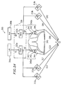
signal processing section 370 of thesound reproducing apparatus 304 includesfilters image expanding section 352. The outputs of the soundimage expanding section 352 are applied to theloudspeaker systems image expanding section 352 can be constructed, for example, by a DSP, and the like, similar to thefilters image expanding section 352 transforms the input sound signal so that the effect sound can be reproduced from only thefront loudspeaker systems image expanding section 352 is set to be (CL0+CL1+CL2)/CL0, and the transfer function JR of the Rch is set to be (CR0+CR1+CR2)/CR0. - Figure 26 shows an exemplary specific construction for the sound
image expanding section 352. In Figure 26, the Lch and Rch signals are applied to inputterminals input terminal 101a is branched into four signals. Three of the four signals are connected to delay circuits (delay: D) 102a, 103a, and 104a. Similarly, the signal input through theinput terminal 101b is branched into four signals. Three of the four signals are connected to delay circuits (delay: D) 102b, 103b, and 104b. The outputs of thedelay circuits input terminal 101a are connected to gainadjusters delay circuits input terminal 101b are connected to gainadjusters - The outputs of the
gain adjusters adder 131, the outputs of thegain adjusters operational circuits - The transfer function of the
operational circuit 123a is CL2/CL0, and the transfer function of the operational circuit 124a is CL1/CL0. Similarly, the transfer function of theoperational circuit 123b is CR2/CR0, and the transfer function of theoperational circuit 124b is CR1/CR0. Theseoperational circuit operational circuits 123a and 124a are applied to anadder 132a. The outputs of theoperational circuits adder 132b. The outputs of theadders adders gain adjusters - On the other hand, the output of the
adder 131 is applied to areverberation adding circuit 141. Thereverberation adding circuit 141 is constructed, for example, by a Schroeder circuit or the like, and adds the reverberation sound. The output signal of thereverberation adding circuit 141 is directly supplied to anadder 152b, and supplied to anadder 152a via adelay circuit 151. - The
adder 152a is a circuit for adding the direct sound signal which is the Lch input signal output via thegain adjuster 115a, the sound image moving signal output from thegain adjuster 142a, and the reverberation sound signal output from thedelay circuit 151 to each other. Similarly, theadder 152b is a circuit for adding the direct sound signal which is the Rch input signal output via thegain adjuster 115b, the sound image moving signal output from thegain adjuster 142b, and the reverberation sound signal output from thereverberation adding circuit 141 to each other. - The synthetic Lch sound signal generated by the
adder 152a is output from anoutput terminal 154a via again adjuster 153a. The synthetic Rch sound signal generated by theadder 152b is output from anoutput terminal 154b via again adjuster 153b. - The operation of the
sound reproducing apparatus 304 including thesound expanding section 352 with the above-described construction will be described. Similar to the case in Example 10, as for the frequency characteristics of thefilters loudspeaker systems signal source 310a is processed by thefilter 322a, so as to produce a signal SL' with reduced gains at the resonance frequencies f1, f2, f3, ... of thehorn 344. The signal SL' is input into the soundimage expanding section 352. Similarly, the sound signal SR output from thesignal source 310b is processed by thefilter 322b, so as to produce a signal SR' with reduced gains at the resonance frequencies f1, f2, f3, ... of thehorn 344. The signal SR' is input into the soundimage expanding section 352. - In Figure 26, the signal SL' input to the
input terminal 101a is processed by the delay circuit and the gain adjuster, as described above. Then, the processed signal SL' is input into theadder 132a via theoperational circuit 123a and 124a. At this time, the output of theadder 132a is SL'·(CL1/CL0)+SL'·(CL2/CL0). When the transfer function of thereverberation adding circuit 141 is K/CL0, and the delay of thedelay circuit 151 is indicated by a transfer function D, the output of theadder 152a is represented by:
This synthetic signal is output from theoutput terminal 154a to theloudspeaker system 340a (Figure 25). The output sound wave of the synthetic signal is represented by:
Therefore, the sound wave which reaches the ears of the listener is represented by:
Thus, it is possible to attain the same expanded sound effect as that in the case of thesound reproducing apparatus 303 shown in Figure 24. In the above description, only the Lch signal SL has been described. In the same way, the sound wave for the Rch signal SR can be obtained as SR·{CR0+CR1+CR2+K}. - In this way, prescribed transfer functions are set for the
operational circuits horn 344 are reduced by thefilters horn 344 is removed, as in the characteristic shown in Figure 19. As a result, a sound wave with high clarity can be output. In addition, by the soundimage expanding section 352, a sound image moving effect with a rich sense of presence can be attained without locating effect loudspeakers. - Next, a
sound reproducing apparatus 305 in Example 16 will be described with reference to the relevant figures. Thesound reproducing apparatus 305 is provided for a television system, and has an effect for converting the reproducing velocity of speech signals. As shown in Figure 27, in thesound reproducing apparatus 305, asignal processing section 380 includesfilters speech converter loudspeaker systems ray tube 345 of the television system. In Example 16, in each of theloudspeaker systems cavity 343 and ahorn 344 are provided by utilizing the rear space and the left and right slight spaces of the cathode-ray tube 345. Components which are the same as those in thesound reproducing apparatus 302 in the above-described example are designated by the same reference numerals, and the detailed descriptions thereof are omitted. - Signals from an
Lch signal source 310a and aRch signal source 310b are input into thefilters filters filters speech converters speech converters speech converter loudspeaker systems - The operation of the
sound reproducing apparatus 305 having the above-described construction will be described. As for the frequency characteristic of thefilters loudspeaker systems signal sources filters horn 344. - In general, a speech signal is greatly affected by an accumulated spectrum of the falling characteristic of the reproduce sound pressure frequency characteristic of the loudspeaker system, when the velocity of the speech signal is converted. Figure 28 is a graph showing the reverberation frequency characteristic of the
loudspeaker system 340a (and 340b) including thehorn 344. For example, curve G1 in Figure 28 indicates the reproduction frequency characteristic in the case where the length of the horn of the loudspeaker system is not sufficient. - If a resonance due to the horn occurs in the frequency range of the reproduced sound, the sound pressure is abruptly increased at the resonance frequencies f1, f2, .... If a random signal is shut out in this state, a reverberation vibration occurs in the horn and the diaphragm, so that the intensity of the output spectrum is gradually decreased as time elapses, as shown by curves G2, G3, ...G6 in Figure 28. Though the sound signal from the signal source is blocked, the peaks of sound pressure are retained at the resonance frequencies f1, f2, ... for a short time period in curves G2 to G6. Such a phenomenon degrades the clarity of reproduced sound, so that so-called "sharpness" of the reproduced sound may be poor.
- The signals from the
signal sources filters filters - Next, a
sound reproducing apparatus 306 in Example 17 of the invention will be described. Thesound reproducing apparatus 306 is provided for a television system, and attains an effect for converting the reproducing velocity of speech signals. As shown in Figure 30, in thesound reproducing apparatus 306, asignal processing section 390 includesfilters speech detectors field control sections adders loudspeaker systems ray tube 345 of the television system. In Example 17, in each of theloudspeaker systems cavity 343 and ahorn 344 are provided by utilizing the rear space and the left and right slight spaces of the cathode-ray tube 345. Components which are the same as those in thesound reproducing apparatus 302 in the above-described example are designated by the same reference numerals, and the detailed descriptions thereof are omitted. - Signals from an
Lch signal source 310a and anRch signal source 310b are input into thefilters filters filters speech detectors speech detectors speech detector 354a, the output is applied to the soundfield control section 351a. If the Lch input signal is determined to be a speech signal, the output is applied to theadder 355a. Similarly, if the Rch input signal is determined to be a non-speech signal by thespeech detector 354b, the output is applied to the soundfield control section 351b. If the Rch input signal is determined to be a speech signal, the output is applied to theadder 355b. The outputs of theadders loudspeaker systems - The sound
field control sections field control sections adder 355a adds the speech signal output from thespeech detector 354a to the surround (non-speech) signal output from the soundfield control section 351a. Similarly, theadder 355b adds the speech signal output from thespeech detector 354b to the surround (non-speech) signal output from the soundfield control section 351b. Each of thefilters speech detectors field control sections - The operation of the
sound reproducing apparatus 306 having the above-described construction will be described. The operations of thefilters signal sources filters speech detectors loudspeaker systems adders - Non-speech signals are converted into surround signals by the sound
field control sections - As described above, the signals of a stereo source can be reproduced after the resonance frequency components of the loudspeaker system (the frequency components of the standing wave due to the length of the horn 344) are reduced by the
filters field control sections - Next, a sound reproducing apparatus in Example 18 will be described. The construction of the sound reproducing apparatus in Example 18 is the same as that of the
sound reproducing apparatus 306 in Example 17, except for the construction of asignal processing section 390. Figure 31 is a block diagram showing the construction of thesignal processing section 390 in Example 18. Components having the same functions as those in thesignal processing section 350 in Example 12 are designated by the same reference numerals, and the detailed descriptions thereof are omitted. - In Figure 31, the output signal SL'(t) from the
filter 322a and the output signal SR'(t) from thefilter 322b are applied adifference signal extractor 360 which outputs a difference signal S(t). The difference signal S(t) is input intodelay circuits delay circuits - The signals SL'(t) and SR'(t) are applied to a
signal judging circuit 391 and acorrelator 392. Thesignal judging circuit 391 detects a blank period (i.e. a silent interval where the signal is essentially zero) of the input signal, and judges whether the input signal is a speech signal or non-speech signal. Thecorrelator 392, on the other hand, is a circuit for determining the correlation ratio between input signals. - An output signal S(t-τ1) from the
delay circuit 372, and an output signal S(t-τ2) from thedelay circuit 371 are applied toadders - The output signals of the
delay circuits adders adders signal judging circuit 391 and thecorrelator 392. The resulting signals are output to theloudspeaker systems - The operation of the
signal processing section 390 in Example 18 with the above-described construction will be described as to the different portions from the previous examples. - The
signal judging circuit 391 adds the input signals SR'(t) and SL'(t) to obtain a sum signal, detects the frequency of the blank periods (i.e. how frequently the signal interruptions occur) in the sum signal, and judges whether the input signal is a speech signal or not according to the frequency of the blank periods. - Figure 32 shows the waveform of a speech signal. In Figure 32, the horizontal axis of the coordinate represents the time and the vertical axis of the coordinate represents the amplitude. This sound wave was obtained from the spoken words "DOMO ARIGATO GOZAIMASITA (Thank you very much)" in Japanese as indicated over the waveform. As can be seen from Figure 32, there will always be a certain number of blanks (silent periods) within a certain period of time in a speech signal (in this example there are two blanks in one second period). The
signal judging circuit 391 uses this property of the speech signal to determine whether the input signal is a speech signal or a non-speech signal based on the blank period frequency, and controls the summation ratio of theadders
for a non-speech signal A = (A + ΔA)
for a speech signal A = (A - ΔA)
where ΔA is a constant for varying the amount of the judging value according to whether the signal is a speech signal or not. - When the input signal is determined to be a non-speech signal, the judging value A is increased by the constant ΔA, while when the input signal is determined to be a speech signal, the judging value A is decreased by the constant ΔA. This operation is successively repeated at a predetermined interval and the judging value A is updated at each judgment. In this manner, the input signal is judged by variation ΔA of the judging value A from a previously judged value, and not judged by the
value adders - The
correlator 392 calculates the correlation ratio between the input signals according to following "Equation (28) as described below.
- In the case where the input 2ch signals are a monaural signal or an approximately monaural signal (i.e. the 2ch signals SR'(t) and SL'(t) are strongly correlated with each other), the nominator of the equation is zero or decreases to zero, and the value α becomes nearly zero. When the input 2ch signals are a stereo signal (i.e. the 2ch signals SR'(t) and SL'(t) have no or little correlation each other), the nominator increases, and the value α is also increased.
- The summation ratio of the signals in the
adders signal judging circuit 391 and thecorrelator 392. - The
adders 

where SR''(t) and SL''(t) are output signals from theadders - In these equations, the summing ratios of signals SL'(t) and SR'(t) which are to be localized forwar2dly, and the respective surround signal are adjusted to produce a natural presence. In other words, the correlation ratio between the input signals is small (i.e. giving a listener a large stereophonic feeling), the signal processed by the
difference signal extractor 360 is reproduced large, while when the correlation ratio between the input signals is large (i.e. giving a listener a small stereophonic feeling), the signal processed by thedifference signal extractor 360 is reproduced small. Furthermore, the speech signal may be reproduced clearly since the judgment of the input signal to be a speech signal or not is performed at the same time and the summation ratio is adjusted. - Although a given by Equation (28) is used with a direct form in Equations (29) and (30), in practice, the value α may be converted into a value in a range of about 0 to 1. Furthermore, this value may be varied depending on the desirable magnitude of the stereophonic effects.
- In this example, signals SL'(t) and SR'(t) are multiplied by a factor (1-α·A) in order to suppress the change in the total volume of SL''(t) and SR''(t) according to the change of the value α. However, when the total volume is allowed to change, the input signal is not required to be multiplied by (1-α·A). That is, when a variation of volume can be acceptable, the multiplication is not required.
- The value α·A is updated at a timing with certain time intervals, since the updating operation may cause a fluctuation in the effect.
- The value α indicating the correlation ratio may be used in another form of correlation value instead of the exact form. Similarly to the speech judging value A, the correlation value B may be defined as:
when α > X, B = (B + ΔB)
when α < X, B = (B - ΔB),
where X is a predetermined value and ΔB is a constant for varying the correlation value B. The operation using this correlation value is also able to prevent the output signals from fluctuations caused by the updating timing of a or an erroneous judgment. - According to this example, the input signal is judged to be a speech signal or a non-speech signal by the
signal judging circuit 391 based on the frequency of the blank periods. Alternatively, other methods may be used for judgment such as a determining method based on the inclination of the envelope of a rising edge or falling edge of the input signal waveform, or a combination of this determining method with the method in this example. - In this example, the sum signal of the input signals is judged by the
signal judging circuit 391. Alternatively, each input signal may be judged without summation. Thereafter, the operation is the same as that in Example 1. - Next, a sound reproducing apparatus in Example 19 will be described. The construction of the sound reproducing apparatus in Example 19 is the same as that of the
sound reproducing apparatus 306 in Example 17, except for the construction of asignal processing section 390. Figure 33 is a block diagram showing the construction of thesignal processing section 390 in Example 19. Components having the same functions as those in thesignal processing sections - In Figure 33, the output signal SL'(t) from the
filter 322a and the output signal SR'(t) from thefilter 322b are each divided into two branches. One of the branched signals of SL'(t) and one of the branched signals of SR'(t) are applied to adifference signal extractor 360 and the others toadders difference signal extractor 360 is applied tooperational circuits - The other branched signals of SL'(t) and SR'(t) are applied to a
signal judging circuit 391 and acorrelator 392. - The
signal judging circuit 391 judges whether the input signal is a speech signal or a non-speech signal. Thecorrelator 392 is a circuit for determining the correlation ratio between input signals. - The respective output signals S1(t), S2(t), S3(t), and S4(t) of the
operational circuits adders delay circuits - The
adder 375 weights and adds the input signal SR'(t) from thefilter 322b, and the output signals of thedelay circuits signal judging circuit 391 and thecorrelator 392. Theadder 376 weights and adds the input signal SL'(t) from thefilter 322a, the output signals of thedelay circuit signal judging circuit 391 and thecorrelator 392. The output signals SR1'(t) and SL1'(t) are the signals output from theadders - The results of the
adders loudspeaker systems - The operation of the
signal processing section 390 in Example 19 with the above-described construction will be described as to the different portions from the previous examples. - This example is similar to Example 12 except for the
signal judging circuit 391 and thecorrelator 392. Also the operation is basically the same as that in Example 12. Thesignal judging circuit 391 and thecorrelator 392 operate the same way as that of the corresponding components of Example 18. The operation of theadders - The
adder 375 performs the summing operation according to the following equation:
- In a similar manner, the
adder 376 performs summing operation as shown in following equation:
- The operations of other circuits are similar to those of the previous examples. Also, in order to simplify the structure of the sound field controller, the circuits other than the
signal judging circuit 391, thecorrelator 392, and theadders - Next, a sound reproducing apparatus in Example 20 will be described. The construction of the sound reproducing apparatus in Example 20 is the same as that of the
sound reproducing apparatus 302 in Example 11, except for the construction of asignal processing section 390. Figure 34 is a block diagram showing the construction of thesignal processing section 350 in Example 20. Components having the same functions as those in thesignal processing sections - In Figure 34, the output signal SL'(t) from the
filter 322a and the output signal SR'(t) from thefilter 322b are each divided into two branches. One of the branched signals of SL'(t) and one of the branched signals of SR'(t) are applied to adifference signal extractor 360 and the others toadders difference signal extractor 360 is supplied to reflectionsound generation circuits - The outputs of the reflection
sound generation circuits operational circuits 361 to 364. The outputs of theoperational circuits 361 to 364 are applied toadders delay circuits 365 to 368. - The
adder 369a adds the output signal of thefilter 322a, and the output signals of thedelay circuits adder 369b adds the output signal of thefilter 322b, and the output signals of thedelay circuits - The outputs from the
adders loudspeaker systems - The operation of the
signal processing section 350 in Example 20 having the above-described construction will be described as to the different portions from Example 12. - The difference signal produced from the
difference signal extractor 360 is applied to the reflectionsound generation circuits sound generation circuits - Figures 35A and 35B schematically show a reflection sound series generated by the reflection
sound generation circuits - Figures 36A and 36B show diagrams for explaining the reflection
sound generation circuits signal input terminal 53 and goes through serially connecteddelay elements 54. Each ofdelay elements 54 delays the signal by τi (i = 0 to j-1; i represents a suffix number as in all the following cases). Signals output from thedelay elements 54 are multiplied by tap coefficients indicated by X(i) by multipliers (taps) 55. All the signals output from the respective taps are added to each other by anadder 56. The added (sum) signal is output via anoutput terminal 57. The above-mentioned operation is expressed with digital signals. When analog signals are handled in practice, an A/D converter and a D/A converter are to be provided in order to convert the analog signals into digital signals before being applied to the reflectionsound generation circuits sound generation circuits sound generation circuits delay elements 54 and thetaps 55 as described above, similarly to theoperational circuits 361 to 364 in the above-described examples. In this case, the reflection sound series as shown in Figure 36B can be obtained. In order to set a desirable reflection sound series such as shown in Figure 36B, it is sufficient to appropriately set the delay times τi and the tap coefficients X(i) to the taps and delay elements shown in Figure 36A. The reflectionsound generation circuits sound generation circuits operational circuits 361 to 364 are configured in the same manner, the functional characteristics of the reflectionsound generation circuits operational circuits 361 to 364. - As mentioned above, by adding the reflection sound signal to the difference signal (surround signal), the surround feeling given by the difference signal can be emphasized.
- The output signals of the reflection
sound generation circuits operational circuits 361 to 364. The operations of other circuits are similar to those of Example 12. - Also, to simplify the structure of the sound reproducing apparatus, circuits other than the reflection
sound generation circuits - Next, a sound reproducing apparatus in Example 21 will be described. The construction of the sound reproducing apparatus in Example 21 is the same as that of the
sound reproducing apparatus 306 in Example 17, except for the construction of asignal processing section 390. Figure 37 is a block diagram showing the construction of thesignal processing section 390 in Example 21. Components having the same functions as those in thesignal processing sections - In Figure 37, the output signal SL'(t) from the
filter 322a and the output signal SR'(t) from thefilter 322b are each divided into two branches. One of the branched signals of SL'(t) and one of the branched signals of SR'(t) are applied to adifference signal extractor 360 and the others toadders signal judging circuit 391 for judging whether the input signal is a speech signal or a non-speech signal, and acorrelator 392 for obtaining a correlation ratio between the input signals. - The output of the
difference signal extractor 360 is applied to reflectionsound generation circuits sound generation circuits operational circuits 361 to 364. The outputs of theoperational circuits 361 to 364 are applied toadders delay circuits 366 to 368. - The
adder 375 weighs and adds the output signals from thefilter 322b, and thedelay circuits signal judging circuit 391 and thecorrelator 392. Theadder 376 weighs and adds the output signals from thefilter 322a, and thedelay circuits signal judging circuit 391 and thecorrelator 392. The outputs from theadders loudspeaker systems - The operation of the sound reproducing apparatus of this example is basically similar to that of Example 19 except that each of the signals processed by the
operational circuits 361 to 364 is a sum signal of the difference signal from thedifference signal extractor 360 and the reflection sound signal produced by the reflectionsound generation circuit - Next, a sound reproducing apparatus in Example 22 will be described. The construction of the sound reproducing apparatus in Example 22 is the same as that of the
sound reproducing apparatus 306 in Example 17, except for the construction of asignal processing section 390. Figure 38 is a block diagram showing the construction of thesignal processing section 390 in Example 22. Components having the same functions as those in thesignal processing sections - In Figure 38, the output signal SL'(t) from the
filter 322a and the output signal SR'(t) from thefilter 322b are each divided into two branches. One of the branched signals of SL'(t) and one of the branched signals of SR'(t) are applied to adifference signal extractor 360 and the others toadders signal judging circuit 391 for judging whether the input signal is a speech signal or a non-speech signal, and acorrelator 392 for obtaining a correlation ratio between the input signals. - The output of the
difference signal extractor 360 is supplied to reflectionsound generation circuits sound generation circuits loudspeaker systems adders adders - To the difference signal obtained from the
difference signal extractor 360, reflection sounds are added in the reflectionsound generation circuits adder 375 weights and adds the output signals from thefilter 322b and the reflectionsound generation circuit 393 with respective ratios based on the calculated result obtained from thesignal judging circuit 391 and thecorrelator 392. Theadder 376 weights and adds the output signals from thefilter 322a and the reflectionsound generation circuit 394 with respective ratios based on the calculated result obtained from thesignal judging circuit 391 and thecorrelator 392. The summing operation is performed according to the equations below in a manner similar to Example 19.

- The outputs of the
adders loudspeaker systems - Next, a sound reproducing apparatus in Example 23 will be described. The construction of the sound reproducing apparatus in Example 23 is the same as that of the
sound reproducing apparatus 306 in Example 17, except for the construction of asignal processing section 390. Figure 39 is a block diagram showing the construction of thesignal processing section 390 in Example 23. Components having the same functions as those in thesignal processing sections - In Figure 39, a
multiplier 397 multiplies an input signal by -1, and anadder 396 adds the output signal from thefilter 322a to the output signal from themultiplier 397. Anadder 395 sums the output signals from thefilters sound generation circuits adder 395 and reflectionsound generation circuits adder 396. - The
adders signal judging circuit 391 and thecorrelator 392. The output signals from the reflectionsound generation circuits adders loudspeaker systems - The operation of the
signal processing section 390 in Example 23 having the above-described construction will be described as to the different portions from the previous examples. - The signal SR'(t) output from the
filter 322b is divided into four signals. Three of the four signals are input into theadders filter 322a is divided into four signals. Among the four signals, one is applied to theadder 395, one is first multiplied by -1 in themultiplier 397 and then applied to theadder 396, and one is applied to theadder 376. - The
adder 396 adds the signals SR'(t) and -SL'(t) to each other, and the result, i.e., SR'(t)-SL'(t) is output. That is, themultiplier 397 and theadder 396 function as a difference signal extractor. The output from theadder 396 is divided into two signals which are fed to the reflectionsound generation circuits adders - Similarly, the
adder 395 adds the signals SR'(t) and SL'(t) to each other, and the result, i.e., SR'(t)+SL'(t) is output. That is, theadder 395 functions as a sum signal generation means. The output from theadder 395 is divided into two signals which are fed to the reflectionsound generation circuits adders - The
adder 375 receives the output signals S1'(t) and S2'(t) of the reflectionsound generation circuits filter 322b. Theadder 376 receives the output signals S3'(t) and S4'(t) of the reflectionsound generation circuits filter 322a. Theadders 

- The reflection
sound generation circuits sound generation circuits - By providing the reflection sound generation circuits and adding the reflection sound to the difference signal of the input signals as described above, a sound field can be reproduced with natural expansion and natural presence without the antiphase feeling. Furthermore, providing two reflection sound generation circuits for each channel makes it possible to reproduce a sound field in which the signals produced from the
loudspeaker systems - Next, a sound reproducing apparatus in Example 24 will be described. The construction of the sound reproducing apparatus in Example 24 is the same as that of the
sound reproducing apparatus 306 in Example 17, except for the construction of asignal processing section 390. Figure 40 is a block diagram showing the construction of thesignal processing section 390 in Example 24. Components having the same functions as those in thesignal processing sections - In Figure 40, a
multiplier 397 multiplies an input signal by -1, andadders signal judging circuit 391 and thecorrelator 392. The output signals of theadders adder 378b are denoted by SS1(t) and SS3(t), the output signal of themultiplier 379 is denoted by SS2(t), and the output signal of theadder 378a is denoted by SS4(t). - The operation of the
signal processing section 390 in Example 24 having the above-described construction will be described as to the different portions from Example 23. - The output signals from the reflection
sound generation circuits adders adder 378b adds the outputs of the reflectionsound generation circuits adder 375 and the other is fed to theadder 376. - The
adder 378a adds the outputs of the reflectionsound generation circuits multiplier 379, and the other is fed to theadder 376. In themultiplier 379, the output of theadder 378a is multiplied by -1, and the result is applied to theadder 375. - The
adder 375 receives the output signal SS1(t) of theadder 378b, the output signal SS2(t) of themultiplier 379, and the signal SR'(t) output from thefilter 322b. Theadder 376 receives the output signal SS3(t) of theadder 378b, the output signal SS4(t) of theadder 378a, and the output signal SL'(t) output from thefilter 322a. The summation is performed in a manner similar to Example 19.

- The output signals SR4'(t) and SL4'(t) are reproduced from the
loudspeaker systems - In this way, the outputs of the reflection
sound generation circuits loudspeaker system 340b in the same phase (i.e., inphase) with each other. On the other hand, the outputs of the reflectionsound generation circuits loudspeaker system 340a in antiphase. - As described above, the difference signal and the sum signal of the stereo signals are each divided into two portions. One portion of the difference signal and one portion of the sum signal are reproduced in inphase, and the other portion of the difference signal and the other portion of the sum signal are reproduced in antiphase. Consequently, the feeling of expansion is obtained by antiphase reproduction, and at the same time, any uncomfortable antiphase feeling can be reduced by adding the inphase signals to the antiphase signals to be reproduced.
- Various other modifications will be apparent to and can be readily made by those skilled in the art without departing from the scope and spirit of this invention. Accordingly, it is not intended that the scope of the claims appended hereto be limited to the description as set forth herein, but rather that the claims be broadly construed.
Claims (39)
- A sound field controller for reproducing a sound field which provides a distance perspective depending on a position of a sound image for a listener, the sound field controller comprising:
an A/D converter for converting an input audio signal into a digital signal;
signal processing means for receiving the digital signal, processing the digital signal using predetermined parameters, and generating a sound signal;
input means for inputting conditions which include a position of a sound image to be localized and a distance from a listener;
parameter control means for setting the parameters in the signal processing means so that the sound signal has characteristics in accordance with the conditions;
a D/A converter for converting the sound signal output from the signal processing means into an analog signal; and
reproduction means for amplifying and reproducing the analog signal output from the D/A converter. - A sound field controller according to claim 1, wherein the signal processing means includes:
direct sound processing means for receiving the digital signal and generating a direct sound signal by which a sound image of a direct sound is localized in a direction toward a sound source;
reflection sound processing means including delay means for receiving the digital signal and delaying the digital signal in accordance with a reflection time of a reflection sound, and means for generating a reflection sound signal by which a sound image of the reflection sound is localized in a direction in which the reflection sound is reflected; and
adding means for adding the direct sound signal to the reflection sound signal. - A sound field controller according to claim 2, wherein the means for generating a reflection sound signal includes filter means, and
the parameter control means sets a delay time in the delay means and filter coefficients for the filter means, based on the position of the sound image and the distance from the listener. - A sound field controller according to claim 2, wherein the signal processing means further includes summation ratio control means for continuously changing ratios of the direct sound signal and the reflection sound signal to be added.
- A sound field controller according to claim 2, wherein the signal processing means further includes reverberation sound generating means for adding a reverberation sound to a signal output from the adding means,
the conditions input from the input means further includes an expansion of a sound field, and
the parameter control means sets a parameter for the reverberation sound generating means based on the expansion of the sound field. - A sound field controller according to claim 1, wherein the conditions input from the input means includes the position of the sound image, the distance from the listener, and an expansion of a sound field, and
the signal processing means includes:
direct sound processing means for receiving the digital signal and generating a direct sound signal by which a sound image of a direct sound is localized in a direction toward a sound source;
reflection sound processing means including delay means for receiving the digital signal and delaying the digital signal in accordance with a reflection time of a reflection sound, and means for generating a reflection sound signal by which a sound image of the reflection sound is localized in a direction in which the reflection sound is reflected;
summation ratio control means for adding the direct sound signal to the reflection sound signal by continuously changing summation ratios thereof, and outputting a sum signal; and
reverberation sound generating means for adding a reverberation sound to the sum signal output from the summation ratio control means. - A sound field controller according to claim 2, wherein the signal processing means includes frequency characteristic control means for changing frequency characteristics of the direct sound signal and the reflection sound signal.
- A sound field controller according to claim 7, wherein the signal processing means further includes summation ratio control means for continuously changing summation ratios of the direct sound signal and the reflection sound signal to be added.
- A sound field controller according to claim 1, wherein the input means is parameter receiving means for receiving sound field control signals supplied from the outside of the sound field controller.
- A sound field controller according to claim 1, wherein the signal processing means includes:
direct sound processing means for receiving the digital signal and generating a direct sound signal;
reflection sound processing means including a plurality of delay means for receiving and delaying the digital signal in accordance with respective reflection times of a plurality of reflection sounds and generating a plurality of delay signals, and means for outputting reflection sound signals by adjusting respective gains for the delay signals; and
adding means for adding the direct sound signal to the reflection sound signals. - A sound field controller according to claim 7, wherein the conditions include a side reflection angle which is formed by a direction of a reflection sound which reaches the listener after being emitted from a sound source and then reflected from a wall of an audio space with respect to a direction from the sound source to the listener, and
the parameter control means converts the side reflection angle into a parameter of a position of a listener and/or a parameter of a position of a sound image, and inputs the parameter into the signal processing means. - A sound reproducing apparatus in which a signal from a sound signal source is processed by signal processing means, and the processed sound signal is reproduced from loudspeaker systems, wherein
each of the loudspeaker systems includes a horn for guiding a sound wave emitted from a front face of a diaphragm of a loudspeaker unit, and has a resonance frequency due to the horn, and
the signal processing means includes filter means for receiving the signal, attenuating the resonance frequency components of the signal in a frequency band of a sound to be reproduced, and outputting a resulting sound signal. - A sound reproducing apparatus in which a signal from a sound signal source is processed by signal processing means, and the processed sound signal is reproduced from a loudspeaker system and rear loudspeakers, respectively, wherein
the loudspeaker system includes loudspeaker units located on front left and front right sides of a listener, and horns for guiding sound waves emitted from front faces of diaphragms of the loudspeaker units, the loudspeaker system having a resonance frequency due to the horns,
the rear loudspeakers are located on rear left and rear right sides of the listener, and
the signal processing means includes means for generating a surround signal from the signals, and filter means for receiving the signal, attenuating the resonance frequency components of the signal in a frequency band of a sound to be reproduced, and outputting a resulting sound signal. - An apparatus according to claim 12, wherein the loudspeaker systems are located on front left and front right sides of a listener, and
the signal processing means further includes sound field control means for receiving the sound signal, converting the sound signal so that a sound image of the sound signal is localized at a desired position, and outputting the converted signal to the loudspeaker systems. - A sound reproducing apparatus in which a signal from a sound signal source is processed by signal processing means, and the processed sound signal is reproduced from a loudspeaker system and effect loudspeakers, respectively, wherein
the loudspeaker system includes loudspeaker units located on front left and front right sides of a listener, and horns for guiding sound waves emitted from front faces of diaphragms of the loudspeaker units, the loudspeaker system having a resonance frequency caused by the horns,
the effect loudspeakers are located on the outer left and right sides of the loudspeaker system, the effect loudspeakers reproducing an expansion sound, and
the signal processing means includes filter means for receiving the signal, attenuating the resonance frequency components of the signal in a frequency band of a sound to be reproduced, and outputting a resulting sound signal to the loudspeaker system and the effect loudspeakers. - A sound reproducing apparatus according to claim 12, wherein the loudspeaker systems are located on front left and front right sides of a listener, and
the signal processing means further includes a sound image expansion means for receiving the sound signal, converting the received sound signal so that a sound image of the sound signal is localized on front left and front right sides of the listener, and on outer left and right sides thereof, and outputting the converted signal to the loudspeaker systems, whereby an expanded sound including a moving sound is reproduced from the loudspeaker systems. - A sound reproducing apparatus according to claim 12, wherein the loudspeaker systems are located on front left and front right sides of a listener, and
the signal processing means further includes speech conversion means for receiving the sound signal, converting, when the received sound signal is judged to be a speech signal, a reproducing velocity of the speech signal, and outputting the speech signal to the loudspeaker systems. - A sound reproducing apparatus according to claim 12, wherein the loudspeaker systems are located on front left and front right sides of a listener, and the signal processing means includes:
speech judging means for receiving the sound signal, judging whether the sound signal is a speech signal or a non-speech signal, and outputting the speech signal and the non-speech signal separately from each other;
sound field control means for receiving the non-speech signal, converting the non-speech signal so that a sound image of the non-speech signal is localized at a desired position, and outputting the converted signal; and
adding means for receiving and adding the converted signal and the speech signal to each other, and outputting the added signal to the loudspeaker systems. - A sound reproducing apparatus according to claim 12, wherein the filter means reduces a gain of the sound signal at the resonance frequency, so that a sound pressure of a reproduced sound at the resonance frequency of the loudspeaker systems is equal to or lower than a predetermined level.
- A sound reproducing apparatus according to claim 12, wherein the loudspeaker systems are provided on side faces of a cathode-ray tube of a television image receiver, respectively.
- A sound reproducing apparatus according to claim 12, wherein a cross-sectional area of the horn is increased from the front face of the diaphragm of the loudspeaker unit toward an opening from which the sound wave is emitted.
- A sound reproducing apparatus according to claim 12, wherein a cross-sectional area of the horn is substantially uniform from the front face of the diaphragm of the loudspeaker unit toward an opening from which the sound wave is emitted.
- A sound field control method for reproducing a sound field which provides a distance perspective depending on a position of a sound image for a listener, the method comprising the steps of:
converting an input audio signal into a digital signal;
processing the digital signal using predetermined parameters, and generating a sound signal;
setting conditions which include a position of a sound image to be localized and a distance from a listener;
controlling the parameters used in the signal processing step so that the sound signal has characteristics in accordance with the conditions;
converting the sound signal into an analog signal; and
amplifying and reproducing the analog signal. - A sound field control method according to claim 23, wherein the signal processing step includes the steps of:
processing the digital signal so as to generate a direct sound signal for localizing a sound image of a direct sound in a direction toward a sound source;
delaying the digital signal in accordance with a reflection time of a reflection sound, and processing the delayed digital signal so as to generate a reflection sound signal for localizing a sound image of the reflection sound in a direction in which the reflection sound is reflected; and
adding the direct sound signal and the reflection sound signal. - A sound field control method according to claim 24, wherein the step of generating a reflection sound signal includes a filtering step, and
the step of controlling the parameters includes a step of setting a delay time of the digital signal and a step of setting filter coefficients for the filtering step, based on the position of the sound image and the distance from the listener. - A sound field control method according to claim 24, wherein the signal processing step further includes a step of continuously changing summation ratios of the direct sound signal and the reflection sound signal to be added.
- A sound field control method according to claim 24, wherein the signal processing step further includes a step of adding a reverberation sound to a sum signal generated in the adding step,
the conditions further includes an expansion of a sound field, and
the parameter control step further includes a step of setting a parameter for the step of adding a reverberation sound based on the expansion of the sound field. - A sound field control method according to claim 23, wherein the conditions includes the position of the sound image, the distance from the listener, and an expansion of a sound field, and
the signal processing step includes the steps of:
processing the digital signal so as to generate a direct sound signal for localizing a sound image of a direct sound in a direction toward a sound source;
delaying the digital signal in accordance with a reflection time of a reflection sound, and processing the delayed digital signal so as to generate a reflection sound signal for localizing a sound image of the reflection sound in a direction in which the reflection sound is reflected;
adding the direct sound signal and the reflection sound signal by continuously changing summation ratios thereof, and outputting a sum signal; and
adding a reverberation sound signal to the sum signal in accordance with the expansion of the sound field. - A sound field control method according to claim 24, wherein the signal processing step further includes a step of controlling frequency characteristics of the direct sound signal and the reflection sound signal.
- A sound field control method according to claim 29, wherein the signal processing step further includes a step of continuously changing summation ratios of the direct sound signal and the reflection sound signal to be added.
- A sound field control method according to claim 23, wherein the step of setting the conditions includes a step of receiving sound field control signals supplied from the outside of the sound field controller and a step of determining conditions based on the control signals.
- A sound field control method according to claim 23, wherein the signal processing step includes the steps of:
processing the digital signal so as to generate a direct sound signal;
delaying the digital signal in accordance with respective reflection times of a plurality of reflection sounds, generating a plurality of delay signals, and adjusting respective gains for the delay signals so as to generate reflection sound signals; and
adding the direct sound signal and the reflection sound signals. - A sound field control method according to claim 29, wherein the conditions include a side reflection angle which is formed by a direction of a reflection sound which reaches the listener after being emitted from a sound source and then reflected from a wall of an audio space with respect to a direction from the sound source to the listener, and
in the step of controlling the parameters, the side reflection angle is converted into a parameter of a position of a listener and/or a parameter of a position of a sound image. - A sound reproducing method comprising the steps of processing a signal from a sound signal source, and reproducing the processed sound signal from loudspeaker systems, each of the loudspeaker systems including a horn for guiding a sound wave emitted from a front face of a diaphragm of a loudspeaker unit, and each of the loudspeaker systems having a resonance frequency due to the horn, wherein
the processing step includes a filtering step of receiving the signal, attenuating the resonance frequency components of the signal in a frequency band of a sound to be reproduced, and outputting a resulting sound signal. - A method according to claim 34, wherein the loudspeaker systems are located on front left and front right sides of a listener, and
the processing step further includes a sound field control step for converting the sound signal so that a sound image of the sound signal is localized at a desired position, and outputting the converted signal to the loudspeaker systems. - A method according to claim 34, wherein the loudspeaker systems are located on front left and front right sides of a listener, and
the signal processing step further includes a sound image expansion step of converting the received sound signal so that a sound image of the sound signal is localized on front left and front right sides of the listener, and on outer left and right sides thereof, and outputting the converted signal to the loudspeaker systems, whereby an expanded sound including a moving sound is reproduced from the loudspeaker systems. - A method according to claim 34, wherein the loudspeaker systems are located on front left and front right sides of a listener, and
the signal processing step further includes a speech conversion step of converting, when the sound signal is judged to be a speech signal, a reproducing velocity of the speech signal, and outputting the speech signal to the loudspeaker systems. - A method according to claim 34, wherein the loudspeaker systems are located on front left and front right sides of a listener, and
the signal processing step includes:
a step of judging whether the sound signal is a speech signal or a non-speech signal, and outputting the speech signal and the non-speech signal separately from each other;
a sound field control step of converting the non-speech signal so that a sound image of the non-speech signal is localized at a desired position, and outputting the converted signal; and
a step of adding the converted signal and the speech signal to each other, and outputting the added signal to the loudspeaker systems. - A method according to claim 34, wherein in the filtering step, a gain of the sound signal at the resonance frequency is reduced, so that a sound pressure of a reproduced sound at the resonance frequency of the loudspeaker systems is equal to or lower than a predetermined level.
Applications Claiming Priority (9)
| Application Number | Priority Date | Filing Date | Title |
|---|---|---|---|
| JP6032993A JPH07222297A (en) | 1994-02-04 | 1994-02-04 | Sound field reproducing device |
| JP32993/94 | 1994-02-04 | ||
| JP3299394 | 1994-02-04 | ||
| JP9804094 | 1994-04-11 | ||
| JP6098040A JPH07284188A (en) | 1994-04-11 | 1994-04-11 | Acoustic reproducing device |
| JP98040/94 | 1994-04-11 | ||
| JP102114/94 | 1994-04-15 | ||
| JP10211494 | 1994-04-15 | ||
| JP10211494A JPH07288899A (en) | 1994-04-15 | 1994-04-15 | Sound field reproducing device |
Publications (3)
| Publication Number | Publication Date |
|---|---|
| EP0666556A2 true EP0666556A2 (en) | 1995-08-09 |
| EP0666556A3 EP0666556A3 (en) | 1998-02-25 |
| EP0666556B1 EP0666556B1 (en) | 2005-02-02 |
Family
ID=27287929
Family Applications (1)
| Application Number | Title | Priority Date | Filing Date |
|---|---|---|---|
| EP95101466A Expired - Lifetime EP0666556B1 (en) | 1994-02-04 | 1995-02-03 | Sound field controller and control method |
Country Status (3)
| Country | Link |
|---|---|
| US (1) | US5742688A (en) |
| EP (1) | EP0666556B1 (en) |
| DE (1) | DE69533973T2 (en) |
Cited By (5)
| Publication number | Priority date | Publication date | Assignee | Title |
|---|---|---|---|---|
| WO1997043755A1 (en) * | 1996-05-13 | 1997-11-20 | Constantinov Christian H | Personal audio communicator |
| EP0814638A2 (en) * | 1996-06-21 | 1997-12-29 | Yamaha Corporation | Three-dimensional sound reproducing apparatus and a three-dimensional sound reproduction method |
| EP0833302A2 (en) * | 1996-09-27 | 1998-04-01 | Yamaha Corporation | Sound field reproducing device |
| EP0827361A3 (en) * | 1996-08-29 | 2007-12-26 | Fujitsu Limited | Three-dimensional sound processing system |
| EP3096539A4 (en) * | 2014-01-16 | 2017-09-13 | Sony Corporation | Sound processing device and method, and program |
Families Citing this family (42)
| Publication number | Priority date | Publication date | Assignee | Title |
|---|---|---|---|---|
| US6091894A (en) * | 1995-12-15 | 2000-07-18 | Kabushiki Kaisha Kawai Gakki Seisakusho | Virtual sound source positioning apparatus |
| JPH09198089A (en) * | 1996-01-19 | 1997-07-31 | Matsushita Electric Ind Co Ltd | Reproduction speed converting device |
| US5857201A (en) | 1996-06-18 | 1999-01-05 | Wright Strategies, Inc. | Enterprise connectivity to handheld devices |
| JP3885976B2 (en) * | 1996-09-12 | 2007-02-28 | 富士通株式会社 | Computer, computer system and desktop theater system |
| US5912976A (en) * | 1996-11-07 | 1999-06-15 | Srs Labs, Inc. | Multi-channel audio enhancement system for use in recording and playback and methods for providing same |
| US5977471A (en) * | 1997-03-27 | 1999-11-02 | Intel Corporation | Midi localization alone and in conjunction with three dimensional audio rendering |
| US6078669A (en) * | 1997-07-14 | 2000-06-20 | Euphonics, Incorporated | Audio spatial localization apparatus and methods |
| US5991385A (en) * | 1997-07-16 | 1999-11-23 | International Business Machines Corporation | Enhanced audio teleconferencing with sound field effect |
| JP3514639B2 (en) * | 1998-09-30 | 2004-03-31 | 株式会社アーニス・サウンド・テクノロジーズ | Method for out-of-head localization of sound image in listening to reproduced sound using headphones, and apparatus therefor |
| JP4499206B2 (en) * | 1998-10-30 | 2010-07-07 | ソニー株式会社 | Audio processing apparatus and audio playback method |
| JP2001028799A (en) * | 1999-05-10 | 2001-01-30 | Sony Corp | Onboard sound reproduction device |
| JP2001186600A (en) * | 1999-12-24 | 2001-07-06 | Matsushita Electric Ind Co Ltd | Sound image localization device |
| US20020046299A1 (en) * | 2000-02-09 | 2002-04-18 | Internet2Anywhere, Ltd. | Method and system for location independent and platform independent network signaling and action initiating |
| JP4275848B2 (en) * | 2000-10-23 | 2009-06-10 | パイオニア株式会社 | Sound field measuring apparatus and sound field measuring method |
| JP2002314676A (en) * | 2001-04-17 | 2002-10-25 | Toshiba Corp | Sound recording and reproducing device |
| FR2852779B1 (en) * | 2003-03-20 | 2008-08-01 | PROCESS FOR PROCESSING AN ELECTRICAL SIGNAL OF SOUND | |
| US7171190B2 (en) * | 2003-06-25 | 2007-01-30 | Oracle International Corporation | Intelligent messaging |
| US6937737B2 (en) * | 2003-10-27 | 2005-08-30 | Britannia Investment Corporation | Multi-channel audio surround sound from front located loudspeakers |
| JP2006101461A (en) * | 2004-09-30 | 2006-04-13 | Yamaha Corp | Stereophonic acoustic reproducing apparatus |
| US7653447B2 (en) | 2004-12-30 | 2010-01-26 | Mondo Systems, Inc. | Integrated audio video signal processing system using centralized processing of signals |
| US8015590B2 (en) * | 2004-12-30 | 2011-09-06 | Mondo Systems, Inc. | Integrated multimedia signal processing system using centralized processing of signals |
| US8880205B2 (en) * | 2004-12-30 | 2014-11-04 | Mondo Systems, Inc. | Integrated multimedia signal processing system using centralized processing of signals |
| EP1901583B1 (en) * | 2005-06-30 | 2011-07-27 | Panasonic Corporation | Sound image localization control apparatus |
| JP4602204B2 (en) * | 2005-08-31 | 2010-12-22 | ソニー株式会社 | Audio signal processing apparatus and audio signal processing method |
| JP4479644B2 (en) * | 2005-11-02 | 2010-06-09 | ソニー株式会社 | Signal processing apparatus and signal processing method |
| JP4637725B2 (en) * | 2005-11-11 | 2011-02-23 | ソニー株式会社 | Audio signal processing apparatus, audio signal processing method, and program |
| JP4914124B2 (en) * | 2006-06-14 | 2012-04-11 | パナソニック株式会社 | Sound image control apparatus and sound image control method |
| JP4835298B2 (en) * | 2006-07-21 | 2011-12-14 | ソニー株式会社 | Audio signal processing apparatus, audio signal processing method and program |
| JP4894386B2 (en) * | 2006-07-21 | 2012-03-14 | ソニー株式会社 | Audio signal processing apparatus, audio signal processing method, and audio signal processing program |
| JP5082327B2 (en) * | 2006-08-09 | 2012-11-28 | ソニー株式会社 | Audio signal processing apparatus, audio signal processing method, and audio signal processing program |
| US8050434B1 (en) | 2006-12-21 | 2011-11-01 | Srs Labs, Inc. | Multi-channel audio enhancement system |
| US8126172B2 (en) * | 2007-12-06 | 2012-02-28 | Harman International Industries, Incorporated | Spatial processing stereo system |
| JP4538494B2 (en) * | 2007-12-27 | 2010-09-08 | Okiセミコンダクタ株式会社 | Acoustic effect circuit and processing method |
| JP4917189B2 (en) | 2009-09-01 | 2012-04-18 | パナソニック株式会社 | Digital broadcast transmission apparatus, digital broadcast reception apparatus, and digital broadcast transmission / reception system |
| JP5672748B2 (en) * | 2010-03-31 | 2015-02-18 | ヤマハ株式会社 | Sound field control device |
| EP2661907B8 (en) | 2011-01-04 | 2019-08-14 | DTS, Inc. | Immersive audio rendering system |
| JP5776223B2 (en) * | 2011-03-02 | 2015-09-09 | ソニー株式会社 | SOUND IMAGE CONTROL DEVICE AND SOUND IMAGE CONTROL METHOD |
| EP2909971B1 (en) | 2012-10-18 | 2020-09-02 | Dolby Laboratories Licensing Corporation | Systems and methods for initiating conferences using external devices |
| JP5651813B1 (en) | 2013-06-20 | 2015-01-14 | パナソニックIpマネジメント株式会社 | Audio signal processing apparatus and audio signal processing method |
| JP6056842B2 (en) * | 2014-12-26 | 2017-01-11 | ヤマハ株式会社 | Sound field control device |
| FR3052951B1 (en) * | 2016-06-20 | 2020-02-28 | Arkamys | METHOD AND SYSTEM FOR OPTIMIZING THE LOW FREQUENCY AUDIO RENDERING OF AN AUDIO SIGNAL |
| JP7294135B2 (en) * | 2017-10-20 | 2023-06-20 | ソニーグループ株式会社 | SIGNAL PROCESSING APPARATUS AND METHOD, AND PROGRAM |
Citations (8)
| Publication number | Priority date | Publication date | Assignee | Title |
|---|---|---|---|---|
| DE2438719A1 (en) * | 1974-08-12 | 1976-02-26 | Karl Otto Pensgen | Hi-fi cross-over network - is for active or passive loudspeaker boxes and stereophonic sound or isotropic radiators |
| JPS6474839A (en) * | 1987-09-17 | 1989-03-20 | Sanyo Electric Co | Fm radio receiver |
| JPH01109997A (en) * | 1987-10-23 | 1989-04-26 | Matsushita Electric Ind Co Ltd | Sound field controller |
| US4868878A (en) * | 1984-04-09 | 1989-09-19 | Pioneer Electronic Corporation | Sound field correction system |
| US5170435A (en) * | 1990-06-28 | 1992-12-08 | Bose Corporation | Waveguide electroacoustical transducing |
| EP0550159A2 (en) * | 1991-12-05 | 1993-07-07 | Salon Televisiotehdas Oy | Loudspeaker for television set |
| WO1994024836A1 (en) * | 1993-04-20 | 1994-10-27 | Sixgraph Technologies Ltd | Interactive sound placement system and process |
| US5371799A (en) * | 1993-06-01 | 1994-12-06 | Qsound Labs, Inc. | Stereo headphone sound source localization system |
Family Cites Families (15)
| Publication number | Priority date | Publication date | Assignee | Title |
|---|---|---|---|---|
| US4308423A (en) * | 1980-03-12 | 1981-12-29 | Cohen Joel M | Stereo image separation and perimeter enhancement |
| DE3112874C2 (en) * | 1980-05-09 | 1983-12-15 | Peter Michael Dipl.-Ing. 8000 München Pfleiderer | Method for signal processing for the reproduction of a sound recording via headphones and device for carrying out the method |
| JPS575499A (en) * | 1980-06-12 | 1982-01-12 | Mitsubishi Electric Corp | Acoustic reproducing device |
| US4569074A (en) * | 1984-06-01 | 1986-02-04 | Polk Audio, Inc. | Method and apparatus for reproducing sound having a realistic ambient field and acoustic image |
| JPS61281799A (en) * | 1985-06-07 | 1986-12-12 | Dainabekutaa Kk | Sound signal reproducing system |
| JPH0775432B2 (en) * | 1988-05-02 | 1995-08-09 | 松下電器産業株式会社 | Speaker system |
| US4792974A (en) * | 1987-08-26 | 1988-12-20 | Chace Frederic I | Automated stereo synthesizer for audiovisual programs |
| US5105462A (en) * | 1989-08-28 | 1992-04-14 | Qsound Ltd. | Sound imaging method and apparatus |
| US5027403A (en) * | 1988-11-21 | 1991-06-25 | Bose Corporation | Video sound |
| US5146507A (en) * | 1989-02-23 | 1992-09-08 | Yamaha Corporation | Audio reproduction characteristics control device |
| EP0462285B1 (en) * | 1989-12-29 | 1996-09-04 | Fujitsu Ten, Ltd. | Acoustic reproducing device |
| US5386082A (en) * | 1990-05-08 | 1995-01-31 | Yamaha Corporation | Method of detecting localization of acoustic image and acoustic image localizing system |
| EP0553832B1 (en) * | 1992-01-30 | 1998-07-08 | Matsushita Electric Industrial Co., Ltd. | Sound field controller |
| EP0593228B1 (en) * | 1992-10-13 | 2000-01-05 | Matsushita Electric Industrial Co., Ltd. | Sound environment simulator and a method of analyzing a sound space |
| US5555310A (en) * | 1993-02-12 | 1996-09-10 | Kabushiki Kaisha Toshiba | Stereo voice transmission apparatus, stereo signal coding/decoding apparatus, echo canceler, and voice input/output apparatus to which this echo canceler is applied |
-
1995
- 1995-02-03 EP EP95101466A patent/EP0666556B1/en not_active Expired - Lifetime
- 1995-02-03 DE DE69533973T patent/DE69533973T2/en not_active Expired - Fee Related
- 1995-02-03 US US08/383,295 patent/US5742688A/en not_active Expired - Fee Related
Patent Citations (8)
| Publication number | Priority date | Publication date | Assignee | Title |
|---|---|---|---|---|
| DE2438719A1 (en) * | 1974-08-12 | 1976-02-26 | Karl Otto Pensgen | Hi-fi cross-over network - is for active or passive loudspeaker boxes and stereophonic sound or isotropic radiators |
| US4868878A (en) * | 1984-04-09 | 1989-09-19 | Pioneer Electronic Corporation | Sound field correction system |
| JPS6474839A (en) * | 1987-09-17 | 1989-03-20 | Sanyo Electric Co | Fm radio receiver |
| JPH01109997A (en) * | 1987-10-23 | 1989-04-26 | Matsushita Electric Ind Co Ltd | Sound field controller |
| US5170435A (en) * | 1990-06-28 | 1992-12-08 | Bose Corporation | Waveguide electroacoustical transducing |
| EP0550159A2 (en) * | 1991-12-05 | 1993-07-07 | Salon Televisiotehdas Oy | Loudspeaker for television set |
| WO1994024836A1 (en) * | 1993-04-20 | 1994-10-27 | Sixgraph Technologies Ltd | Interactive sound placement system and process |
| US5371799A (en) * | 1993-06-01 | 1994-12-06 | Qsound Labs, Inc. | Stereo headphone sound source localization system |
Non-Patent Citations (3)
| Title |
|---|
| MATSUSHITA Y ET AL: "A DIGITAL AUDIO SIGNAL PROCESSOR FOR SOUND FIELD CONTROLS" IEEE TRANSACTIONS ON CONSUMER ELECTRONICS, vol. 37, no. 1, 1 February 1991, pages 28-31, XP000225257 * |
| PATENT ABSTRACTS OF JAPAN vol. 013, no. 295 (E-783), 7 July 1989 & JP 01 074839 A (SANYO ELECTRIC CO LTD), 20 March 1989, * |
| PATENT ABSTRACTS OF JAPAN vol. 013, no. 350 (E-800), 7 August 1989 & JP 01 109997 A (MATSUSHITA ELECTRIC IND CO LTD), 26 April 1989, * |
Cited By (15)
| Publication number | Priority date | Publication date | Assignee | Title |
|---|---|---|---|---|
| WO1997043755A1 (en) * | 1996-05-13 | 1997-11-20 | Constantinov Christian H | Personal audio communicator |
| US7082201B2 (en) | 1996-06-21 | 2006-07-25 | Yamaha Corporation | Three-dimensional sound reproducing apparatus and a three-dimensional sound reproduction method |
| EP0814638A2 (en) * | 1996-06-21 | 1997-12-29 | Yamaha Corporation | Three-dimensional sound reproducing apparatus and a three-dimensional sound reproduction method |
| EP0814638A3 (en) * | 1996-06-21 | 2003-03-19 | Yamaha Corporation | Three-dimensional sound reproducing apparatus and a three-dimensional sound reproduction method |
| US6850621B2 (en) | 1996-06-21 | 2005-02-01 | Yamaha Corporation | Three-dimensional sound reproducing apparatus and a three-dimensional sound reproduction method |
| US7076068B2 (en) | 1996-06-21 | 2006-07-11 | Yamaha Corporation | Three-dimensional sound reproducing apparatus and a three-dimensional sound reproduction method |
| EP0827361A3 (en) * | 1996-08-29 | 2007-12-26 | Fujitsu Limited | Three-dimensional sound processing system |
| EP0833302A3 (en) * | 1996-09-27 | 1999-03-10 | Yamaha Corporation | Sound field reproducing device |
| EP0833302A2 (en) * | 1996-09-27 | 1998-04-01 | Yamaha Corporation | Sound field reproducing device |
| EP3096539A4 (en) * | 2014-01-16 | 2017-09-13 | Sony Corporation | Sound processing device and method, and program |
| US10477337B2 (en) | 2014-01-16 | 2019-11-12 | Sony Corporation | Audio processing device and method therefor |
| US10694310B2 (en) | 2014-01-16 | 2020-06-23 | Sony Corporation | Audio processing device and method therefor |
| US10812925B2 (en) | 2014-01-16 | 2020-10-20 | Sony Corporation | Audio processing device and method therefor |
| US11223921B2 (en) | 2014-01-16 | 2022-01-11 | Sony Corporation | Audio processing device and method therefor |
| US11778406B2 (en) | 2014-01-16 | 2023-10-03 | Sony Group Corporation | Audio processing device and method therefor |
Also Published As
| Publication number | Publication date |
|---|---|
| EP0666556B1 (en) | 2005-02-02 |
| US5742688A (en) | 1998-04-21 |
| DE69533973D1 (en) | 2005-03-10 |
| DE69533973T2 (en) | 2005-06-09 |
| EP0666556A3 (en) | 1998-02-25 |
Similar Documents
| Publication | Publication Date | Title |
|---|---|---|
| US5742688A (en) | Sound field controller and control method | |
| EP1796429B1 (en) | Audio reproduction device with loudspeaker directivity control | |
| EP0865227B1 (en) | Sound field controller | |
| KR100636252B1 (en) | Method and apparatus for spatial stereo sound | |
| US8094827B2 (en) | Sound reproducing apparatus and sound reproducing system | |
| US5119420A (en) | Device for correcting a sound field in a narrow space | |
| US20090110218A1 (en) | Dynamic equalizer | |
| KR0175515B1 (en) | Apparatus and Method for Implementing Table Survey Stereo | |
| US20050135643A1 (en) | Apparatus and method of reproducing virtual sound | |
| AU7637898A (en) | Method and device for reproducing a stereophonic audiosignal | |
| EP0553832A1 (en) | Sound field controller | |
| US20060062398A1 (en) | Speaker distance measurement using downsampled adaptive filter | |
| EP1811809A1 (en) | 3-dimensional acoustic reproduction device | |
| US8009834B2 (en) | Sound reproduction apparatus and method of enhancing low frequency component | |
| JP3594281B2 (en) | Stereo expansion device and sound field expansion device | |
| EP0955789A2 (en) | Method and device for synthesizing a virtual sound source | |
| US20070074621A1 (en) | Method and apparatus to generate spatial sound | |
| CN101278597B (en) | Method and apparatus to generate spatial sound | |
| JPH05260597A (en) | Sound field signal reproduction device | |
| RU2106075C1 (en) | Spatial sound playback system | |
| EP2079252A1 (en) | Sound image localization processing apparatus and others | |
| JP4845407B2 (en) | How to generate a reference filter | |
| JPH0662486A (en) | Acoustic reproducing device | |
| JP2991452B2 (en) | Sound signal reproduction device | |
| RU2042217C1 (en) | Method of forming acoustic field in listening hall and apparatus for performing the method |
Legal Events
| Date | Code | Title | Description |
|---|---|---|---|
| PUAI | Public reference made under article 153(3) epc to a published international application that has entered the european phase |
Free format text: ORIGINAL CODE: 0009012 |
|
| 17P | Request for examination filed |
Effective date: 19950203 |
|
| AK | Designated contracting states |
Kind code of ref document: A2 Designated state(s): DE FR GB IT |
|
| RIN1 | Information on inventor provided before grant (corrected) |
Inventor name: NAKAMA, YASUTOSHI Inventor name: TAMURA, TADASHI Inventor name: DATE, TOSHIHIKO Inventor name: MATSUMOTO, MASAHARU Inventor name: KAWAMURA, AKIHISA Inventor name: OGAWA, MICHIKO |
|
| PUAL | Search report despatched |
Free format text: ORIGINAL CODE: 0009013 |
|
| AK | Designated contracting states |
Kind code of ref document: A3 Designated state(s): DE FR GB IT |
|
| 17Q | First examination report despatched |
Effective date: 20020305 |
|
| GRAP | Despatch of communication of intention to grant a patent |
Free format text: ORIGINAL CODE: EPIDOSNIGR1 |
|
| GRAS | Grant fee paid |
Free format text: ORIGINAL CODE: EPIDOSNIGR3 |
|
| GRAA | (expected) grant |
Free format text: ORIGINAL CODE: 0009210 |
|
| AK | Designated contracting states |
Kind code of ref document: B1 Designated state(s): DE FR GB IT |
|
| REG | Reference to a national code |
Ref country code: GB Ref legal event code: FG4D |
|
| REF | Corresponds to: |
Ref document number: 69533973 Country of ref document: DE Date of ref document: 20050310 Kind code of ref document: P |
|
| PLBE | No opposition filed within time limit |
Free format text: ORIGINAL CODE: 0009261 |
|
| STAA | Information on the status of an ep patent application or granted ep patent |
Free format text: STATUS: NO OPPOSITION FILED WITHIN TIME LIMIT |
|
| 26N | No opposition filed |
Effective date: 20051103 |
|
| ET | Fr: translation filed | ||
| PGFP | Annual fee paid to national office [announced via postgrant information from national office to epo] |
Ref country code: GB Payment date: 20070131 Year of fee payment: 13 |
|
| PGFP | Annual fee paid to national office [announced via postgrant information from national office to epo] |
Ref country code: DE Payment date: 20070201 Year of fee payment: 13 |
|
| PGFP | Annual fee paid to national office [announced via postgrant information from national office to epo] |
Ref country code: IT Payment date: 20070601 Year of fee payment: 13 |
|
| PGFP | Annual fee paid to national office [announced via postgrant information from national office to epo] |
Ref country code: FR Payment date: 20070208 Year of fee payment: 13 |
|
| GBPC | Gb: european patent ceased through non-payment of renewal fee |
Effective date: 20080203 |
|
| REG | Reference to a national code |
Ref country code: FR Ref legal event code: ST Effective date: 20081031 |
|
| PG25 | Lapsed in a contracting state [announced via postgrant information from national office to epo] |
Ref country code: DE Free format text: LAPSE BECAUSE OF NON-PAYMENT OF DUE FEES Effective date: 20080902 |
|
| PG25 | Lapsed in a contracting state [announced via postgrant information from national office to epo] |
Ref country code: FR Free format text: LAPSE BECAUSE OF NON-PAYMENT OF DUE FEES Effective date: 20080229 |
|
| PG25 | Lapsed in a contracting state [announced via postgrant information from national office to epo] |
Ref country code: GB Free format text: LAPSE BECAUSE OF NON-PAYMENT OF DUE FEES Effective date: 20080203 |
|
| PG25 | Lapsed in a contracting state [announced via postgrant information from national office to epo] |
Ref country code: IT Free format text: LAPSE BECAUSE OF NON-PAYMENT OF DUE FEES Effective date: 20080203 |