EP0669109B1 - Stabilisierung von benachbarten Rückenwirbeln - Google Patents
Stabilisierung von benachbarten Rückenwirbeln Download PDFInfo
- Publication number
- EP0669109B1 EP0669109B1 EP94810120A EP94810120A EP0669109B1 EP 0669109 B1 EP0669109 B1 EP 0669109B1 EP 94810120 A EP94810120 A EP 94810120A EP 94810120 A EP94810120 A EP 94810120A EP 0669109 B1 EP0669109 B1 EP 0669109B1
- Authority
- EP
- European Patent Office
- Prior art keywords
- support
- screw
- stabilizer according
- support element
- strap
- Prior art date
- Legal status (The legal status is an assumption and is not a legal conclusion. Google has not performed a legal analysis and makes no representation as to the accuracy of the status listed.)
- Expired - Lifetime
Links
Images


Classifications
-
- A—HUMAN NECESSITIES
- A61—MEDICAL OR VETERINARY SCIENCE; HYGIENE
- A61B—DIAGNOSIS; SURGERY; IDENTIFICATION
- A61B17/00—Surgical instruments, devices or methods, e.g. tourniquets
- A61B17/56—Surgical instruments or methods for treatment of bones or joints; Devices specially adapted therefor
- A61B17/58—Surgical instruments or methods for treatment of bones or joints; Devices specially adapted therefor for osteosynthesis, e.g. bone plates, screws, setting implements or the like
- A61B17/68—Internal fixation devices, including fasteners and spinal fixators, even if a part thereof projects from the skin
- A61B17/70—Spinal positioners or stabilisers ; Bone stabilisers comprising fluid filler in an implant
- A61B17/7001—Screws or hooks combined with longitudinal elements which do not contact vertebrae
- A61B17/7002—Longitudinal elements, e.g. rods
- A61B17/7004—Longitudinal elements, e.g. rods with a cross-section which varies along its length
- A61B17/7008—Longitudinal elements, e.g. rods with a cross-section which varies along its length with parts of, or attached to, the longitudinal elements, bearing against an outside of the screw or hook heads, e.g. nuts on threaded rods
-
- A—HUMAN NECESSITIES
- A61—MEDICAL OR VETERINARY SCIENCE; HYGIENE
- A61B—DIAGNOSIS; SURGERY; IDENTIFICATION
- A61B17/00—Surgical instruments, devices or methods, e.g. tourniquets
- A61B17/56—Surgical instruments or methods for treatment of bones or joints; Devices specially adapted therefor
- A61B17/58—Surgical instruments or methods for treatment of bones or joints; Devices specially adapted therefor for osteosynthesis, e.g. bone plates, screws, setting implements or the like
- A61B17/68—Internal fixation devices, including fasteners and spinal fixators, even if a part thereof projects from the skin
- A61B17/70—Spinal positioners or stabilisers ; Bone stabilisers comprising fluid filler in an implant
- A61B17/7001—Screws or hooks combined with longitudinal elements which do not contact vertebrae
- A61B17/7002—Longitudinal elements, e.g. rods
- A61B17/7019—Longitudinal elements having flexible parts, or parts connected together, such that after implantation the elements can move relative to each other
- A61B17/7031—Longitudinal elements having flexible parts, or parts connected together, such that after implantation the elements can move relative to each other made wholly or partly of flexible material
-
- A—HUMAN NECESSITIES
- A61—MEDICAL OR VETERINARY SCIENCE; HYGIENE
- A61F—FILTERS IMPLANTABLE INTO BLOOD VESSELS; PROSTHESES; DEVICES PROVIDING PATENCY TO, OR PREVENTING COLLAPSING OF, TUBULAR STRUCTURES OF THE BODY, e.g. STENTS; ORTHOPAEDIC, NURSING OR CONTRACEPTIVE DEVICES; FOMENTATION; TREATMENT OR PROTECTION OF EYES OR EARS; BANDAGES, DRESSINGS OR ABSORBENT PADS; FIRST-AID KITS
- A61F2/00—Filters implantable into blood vessels; Prostheses, i.e. artificial substitutes or replacements for parts of the body; Appliances for connecting them with the body; Devices providing patency to, or preventing collapsing of, tubular structures of the body, e.g. stents
- A61F2/02—Prostheses implantable into the body
- A61F2/30—Joints
- A61F2/44—Joints for the spine, e.g. vertebrae, spinal discs
Definitions
- the invention relates to a stabilization of neighboring vertebrae comprising a band and at least two pedicle screws each in one other vertebrae in the direction of their screw axis are anchored with a screw head Have breakthrough transverse to the screw axis through which the tape is retractable, and one each Have clamp screw to the tape across the opening to fix in the direction of the screw axis, and comprising a support element mounted on the belt.
- Patent application WO 91/16018 also shows one Device for generating tensile stresses between two Swirl in the posterior area by placing ligaments between them Pedicle screws are tightened. Such devices can at best generate constant tension.
- the balls With a connection of more than two adjacent vertebrae, the balls must be halved on middle vertebrae to make them one assemble two-piece ball and it must Blind holes with two slots offset by approximately 180 ° be provided.
- the surgeon who Pedicle screws according to the nature and location of the Whirlwind must have an entire arsenal of Damping bodies are present, the ball heads in narrower Gradation have different distances, whereby for any distance damping body with two full balls, with half a ball and a full ball and with two half balls must be present.
- EP-A-0 348 272 are also Pedicle screws are shown with a head on one Threaded blind hole in the direction of the screw axis and across it a continuous slot with a width, smaller than the thread diameter insert connecting rods into the slots, using Screws are attachable.
- Such a solution is one rigid definition of the vertebrae. It requires very large ones Dimensions from the head of the pedicle screws so that the head halves divided by the slit when tightening the Fastening screws are not prohibited be spread apart.
- the object of the invention is a simple and Movable stabilization between vertebrae too create.
- the support element a pressure-resistant body forms for the transfer of pressure forces between the two screw heads, the cross section of the tape in matching holes in the support element and screw head abuts on all sides to support element and screw head center to each other and put the tape between two neighboring pedicle screws over an outside of the Pedicle screws protruding extension can be preloaded is to support element and screw head on one of them common support surface distributed around the belt to be able to support each other.
- the invention has the advantage that two neighboring ones Vortex from a given rest position with one predetermined tension against posterior relieved tension can be without an intervening Intervertebral disc is constantly under pressure in the resting position, while pressure forces are intercepted posteriorly and over Support elements are transferred. There is still one Preserve residual mobility because of support elements and Screw heads in cooperation with the tape a kind Form joint, which with increasing deflection forms increasing resistance to this deflection. It thus arises from the length of the support elements predetermined rest position, out of against one by the prestressing of the belt determines a resetting force limited prevention and lateral twisting between the vertebrae can take place. Likewise, the Screw axes of two through a support element connected pedicle screws slightly skewed to stand by each other.
- a metallic or solid non-metallic Material for the support element is worth it joint support surface to form a spherical Swiveling in any direction with sufficient load-bearing surface to enable. It can be the center of the common Support surface either on the side of the support element or on the side of the screw head of the pedicle screw lie. Because the distance between two in vortex screwed pedicle screws not exactly in advance can determine, the support elements as with a Modules in various lengths are available.
- an elastic support body made of plastic e.g. out Polyurethane is sufficient if there is a flat surface on the screw head Ring surface or an inwardly conical ring surface as Support surface is attached because the plastic give way can and is essentially only claimed under pressure.
- the support surface is only a flat cone ring or corresponds to a flat spherical ring, the Support body centered in it and adapts because of it Elasticity under tension of the support surface, too if it is designed as a cylindrical hollow body.
- the screw head 6 is a section of one Ball body and lies in the saddle 32.
- the screw head 6 is on two opposite support surfaces 13 flattened and has an opening 7 through which a tape is retractable.
- the pedicle screw 2, 3 in neighboring vertebral bodies are aligned so that the support surfaces 13 face each other to interpose a support body which can be pulled onto the belt 1 as in FIGS Figures 2, 4, 6, 7, 8 to introduce.
- the screw head 6 is the Pedicle screws 2, 3 have a through hole 12 attached in a bore 9 of the support member 10th continued to record the tape 1, which under Preload via screws in threaded holes 37 in opposite recesses 31 is clamped.
- the Support surfaces 13 consist of concave on the screw head Annular surfaces 20, which in the case of a rigid support body 10 are spherical 15 with a radius greater than 5 mm, while the support body has a matching spherical counter surface 15 having.
- the screw head is with its spherical surface 30 at the same time support surface for one corresponding concave counter surface on the support body 10. Die remaining elements correspond to those of FIGS. 2, 3.
- the support element consists of a cylindrical hollow body 21 made of elastic Plastic 16, which in the unloaded state each have a circumferential radial incision 38 of divided into two additional sections 25, 26 on the outside is.
- the sections are connected by a neck 24 connected, the neck being so weak that it fully compressed under axial preload so the areas of the incision 38 come into play.
- Notch 38 is only so wide that in the unloaded Condition sections 25, 26 detachable with a scalpel are to the support member 10 to the correct length shorten.
- the support surfaces are on Screw head 6 and conical on the support element 10, the half cone angle 18 is more than 45 °.
- the support body has a bulbous shape 27 towards the center to increase its kink resistance.
- sections 25, 26 - as previously discussed - possible if the radial cuts on Tapered surfaces with a cone angle similar to Cone angle 18 are.
- the cutouts 36 shown in FIGS. 3 and 5 for a screw-in tool are not only used for pulling in the pedicle screws, which are self-tapping with a Thread with constant outside diameter 28 and with a growing core diameter 29 are executed, but are also attachment areas for generating a counter moment when tightening the grub screws 8.
- volume 1 has one round cross-section resistant to shear forces 11 on, for example, braided artificial May have cruciate ligaments.
- a bending load between screw head 6 and support body 10 is therefore a Restoring moment generated by the band 10 stretching, while the pressure in the support surface 13 is one-sided relocated to the outside.
- the screw head designed as a ball cutout 30 occupies only a small volume, which is a deep one Insertion easier, and offers no sharp edges to the neighboring tissue.
- the grub screws 8 should after Complete screwing in flush with spherical surface 30.
- the stabilization described here is not two Adjacent vertebral bodies with an intermediate one Intervertebral disc is limited, but can be connected to each other over several subsequent vertebral bodies are attached to several Stabilize segments.
- the support elements 10 can be slightly curved Pipes can be designed according to the individual location of the to better meet individual pedicle screws.
- the Support surfaces 13 of two pedicle screws 2, 3 to one Support element 10 then need to be less accurate opposite.
Landscapes
- Health & Medical Sciences (AREA)
- Orthopedic Medicine & Surgery (AREA)
- Neurology (AREA)
- Life Sciences & Earth Sciences (AREA)
- Surgery (AREA)
- Engineering & Computer Science (AREA)
- Biomedical Technology (AREA)
- General Health & Medical Sciences (AREA)
- Veterinary Medicine (AREA)
- Heart & Thoracic Surgery (AREA)
- Public Health (AREA)
- Animal Behavior & Ethology (AREA)
- Molecular Biology (AREA)
- Medical Informatics (AREA)
- Nuclear Medicine, Radiotherapy & Molecular Imaging (AREA)
- Cardiology (AREA)
- Oral & Maxillofacial Surgery (AREA)
- Transplantation (AREA)
- Vascular Medicine (AREA)
- Surgical Instruments (AREA)
- Prostheses (AREA)
- Orthopedics, Nursing, And Contraception (AREA)
- Medicines Containing Material From Animals Or Micro-Organisms (AREA)
Description
- Fig. 1
- schematisch einen Querschnitt durch einen Lendenwirbel mit einer eingeschraubten Pedikelschraube;
- Fig. 2
- schematisch die Seitenansicht von zwei Pedikelschrauben, die über ein Stützelement und ein Band miteinander verbunden sind;
- Fig. 3
- schematisch die Draufsicht auf einen der seitlich abgeflachten Schraubenköpfe aus Fig. 2;
- Fig. 4
- schematisch die Seitenansicht von zwei Pedikelschrauben, die über ein Stützelement und ein Band miteinander verbunden sind;
- Fig. 5
- schematisch die Draufsicht auf einen der runden Schraubenköpfe aus Fig. 4;
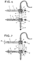
- Fig. 6, 7
- schematisch im nicht vorgespannten Zustand die Seitenansicht von zwei Pedikelschrauben, die über ein elastisches Stützelement und ein Band miteinander verbunden sind;
- Fig. 8
- schematisch im Schnitt ein elastisches Stützelement nach Fig. 6, das zwischen zwei Pedikelschrauben verpresst ist; und
- Fig. 9
- schematisch ein Stützelement aus Fig. 8 im unverpressten Zustand.
Claims (15)
- Stabilisierung von benachbarten Rückenwirbeln umfassend ein Band (1), welches aus elastischem Kunststoff besteht und einen gegen Scherkräfte widerstandsfähigen runden Querschnitt (11) aufweist, und mindestens zwei Pedikelschrauben (2, 3) die jeweils in einem anderen Wirbel in Richtung ihrer Schraubenachse (5) verankerbar sind, die einen Schraubenkopf (6) mit einem Durchbruch (7) quer zur Schraubenachse (5) aufweisen, durch den das Band einziehbar ist, und die jeweils eine Klemmschraube (8) aufweisen, um das Band (1) quer zum Durchbruch (7) in Richtung der Schraubenachse (5) zu fixieren, sowie umfassend ein auf das Band (1) aufgezogenes Stützelement (10), dadurch gekennzeichnet, dass das Stützelement (10) einen druckfesten Körper zur Uebertragung von Druckkräften zwischen zwei Schraubenköpfen bildet, der Querschnitt des Bandes in passenden Bohrungen (9, 12) von Stützelement und Schraubenkopf allseitig anliegt, um Stützelement (10) und Schraubenkopf (6) zueinander zu zentrieren, und dass das Band (1) zwischen zwei benachbarten Pedikelschrauben über eine ausserhalb der Pedikelschrauben vorstehende Verlängerung vorspannbar ist, um Stützelement (10) und Schraubenkopf (6) auf einer ihnen gemeinsamen, um das Band (1) herum verteilten Stützfläche (13) gegenseitig abstützen zu können.
- Stabilisierung nach Anspruch 1, dadurch gekennzeichnet, dass die gemeinsame Stützfläche (13) aus einer ringförmigen Fläche (14) um das Band (1) besteht.
- Stabilisierung nach Anspruch 1 oder 2, dadurch gekennzeichnet, dass das Stützelement (10) aus Metall oder aus einem festen nicht-metallischen Werkstoff besteht.
- Stabilisierung nach Anspruch 3, dadurch gekennzeichnet, dass die gemeinsame Stützfläche (13) ein Ausschnitt aus einer sphärischen Fläche (15) ist, die ihren Mittelpunkt auf der Seite vom Schraubenkopf (6) oder auf der Seite vom Stützelement (10) aufweist.
- Stabilisierung nach Anspruch 3 oder 4, dadurch gekennzeichnet, dass ein Baukastensystem gebildet ist, indem mehrere Stützelemente (10) mit unterschiedlicher Länge auswählbar oder einstellbar sind.
- Stabilisierung nach Anspruch 1 oder 2, dadurch gekennzeichnet, dass das Stützelement (10) aus einem elastischen Kunststoff (16) vorzugsweise aus Polyurethan besteht.
- Stabilisierung nach Anspruch 6, dadurch gekennzeichnet, dass die Stützfläche (13) am Schraubenkopf (6) durch eine ebene Ringfläche (17) oder durch eine nach innen konische Ringfläche (19) mit einem halben Konuswinkel (18) grösser 45° oder durch eine konkave Ringfläche (20) mit einem sphärischen Radius grösser 5 mm gebildet ist.
- Stabilisierung nach Anspruch 6 oder 7, dadurch gekennzeichnet, dass das Stützelement (13) aus einem zylindrischen Hohlkörper (21) besteht.
- Stabilisierung nach Anspruch 8, dadurch gekennzeichnet, dass der zylindrische Hohlkörper (21) durch jeweils einen umlaufenden radialen Einschnitt (38) von aussen in zylindrische Teilstücke (25, 26) unterteilt ist, die durch einen Hals (24) miteinander verbunden sind.
- Stabilisierung nach Anspruch 9, dadurch gekennzeichnet, dass der zylindrische Hohlkörper (21) aus einem mittleren und zwei äusseren Teilstücken (25, 26) besteht, wobei die äusseren Teilstücke (25, 26) mit einem im Einschnitt (38) geführten Skalpell abtrennbar sind und das eine äussere Teilstück (25) die halbe Länge des anderen äusseren Teilstücks (26) aufweist, um durch Abtrennen von keinem, von dem einen, von dem anderen oder von dem einen und dem anderen Teilstück, vier gleichmässig gestufte Einbaulängen zu erhalten.
- Stabilisierung nach Anspruch 6 oder 7, dadurch gekennzeichnet, dass das Stützelement (10) eine mittig bauchige Form (27) aufweist, um die Knickfestigkeit zu erhöhen.
- Stabilisierung nach einem der Ansprüche 1 bis 11, dadurch gekennzeichnet, dass die Pedikelschrauben (2, 3) selbstschneidend mit einem Gewinde mit konstantem Aussendurchmesser (28) und mit einem konisch wachsenden Kerndurchmesser (29) ausgeführt sind.
- Stabilisierung nach einem der Ansprüche 1 bis 12, dadurch gekennzeichnet, dass der Schraubenkopf (6) aus einem Kugelausschnitt (30) besteht, um möglichst geringe Angriffsflächen zu geben.
- Stabilisierung nach einem der Ansprüche 1 bis 13, dadurch gekennzeichnet, dass der Schraubenkopf (6) am Durchbruch (7) in Richtung der Schraubenachse (5) und entgegengesetzt zur Klemmschraube (8) eine Vertiefung (31) aufweist, in welche das Band (1) mit der Klemmschraube einpressbar ist.
- Stabilisierung nach einem der Ansprüche 1 bis 14, dadurch gekennzeichnet, dass das Band (1), die Pedikelschrauben (2, 3) und Stützelemente (10) über mehrere Wirbel fortgesetzt sind, um einen ganzen Bereich zu verstärken.
Priority Applications (6)
| Application Number | Priority Date | Filing Date | Title |
|---|---|---|---|
| AT94810120T ATE180402T1 (de) | 1994-02-28 | 1994-02-28 | Stabilisierung von benachbarten rückenwirbeln |
| DE59408313T DE59408313D1 (de) | 1994-02-28 | 1994-02-28 | Stabilisierung von benachbarten Rückenwirbeln |
| EP94810120A EP0669109B1 (de) | 1994-02-28 | 1994-02-28 | Stabilisierung von benachbarten Rückenwirbeln |
| ES94810120T ES2133517T3 (es) | 1994-02-28 | 1994-02-28 | Estabilizador para vertebras adyacentes. |
| KR1019950000720A KR100354986B1 (ko) | 1994-02-28 | 1995-01-18 | 인접한흉추의안정장치 |
| JP01471095A JP3547514B2 (ja) | 1994-02-28 | 1995-01-31 | 隣接する胸椎用の安定器 |
Applications Claiming Priority (1)
| Application Number | Priority Date | Filing Date | Title |
|---|---|---|---|
| EP94810120A EP0669109B1 (de) | 1994-02-28 | 1994-02-28 | Stabilisierung von benachbarten Rückenwirbeln |
Publications (2)
| Publication Number | Publication Date |
|---|---|
| EP0669109A1 EP0669109A1 (de) | 1995-08-30 |
| EP0669109B1 true EP0669109B1 (de) | 1999-05-26 |
Family
ID=8218215
Family Applications (1)
| Application Number | Title | Priority Date | Filing Date |
|---|---|---|---|
| EP94810120A Expired - Lifetime EP0669109B1 (de) | 1994-02-28 | 1994-02-28 | Stabilisierung von benachbarten Rückenwirbeln |
Country Status (6)
| Country | Link |
|---|---|
| EP (1) | EP0669109B1 (de) |
| JP (1) | JP3547514B2 (de) |
| KR (1) | KR100354986B1 (de) |
| AT (1) | ATE180402T1 (de) |
| DE (1) | DE59408313D1 (de) |
| ES (1) | ES2133517T3 (de) |
Cited By (155)
| Publication number | Priority date | Publication date | Assignee | Title |
|---|---|---|---|---|
| DE10004712C1 (de) * | 2000-02-03 | 2001-08-09 | Aesculap Ag & Co Kg | Knochenplatte |
| US6290700B1 (en) * | 1997-07-31 | 2001-09-18 | Plus Endoprothetik Ag | Device for stiffening and/or correcting a vertebral column or such like |
| EP1153577A1 (de) | 2000-05-12 | 2001-11-14 | Sulzer Orthopedics Ltd. | Verbindung einer Knochenschraube zu einer Knochenplatte |
| GB2382304A (en) * | 2001-10-10 | 2003-05-28 | Dilip Kumar Sengupta | An assembly for soft stabilisation of vertebral bodies of the spine |
| WO2003047441A1 (de) | 2001-12-07 | 2003-06-12 | Mathys Medizinaltechnik Ag | Dämpfungselement |
| EP1364622A2 (de) | 2002-05-21 | 2003-11-26 | Spinelab GmbH | Elastisches Stabilisiersystem für Wirbelsäulen |
| AU767854B2 (en) * | 1999-12-20 | 2003-11-27 | Synthes Gmbh | Device for the stabilisation of two adjacent verterbral bodies of the spine |
| DE10236691A1 (de) * | 2002-08-09 | 2004-02-26 | Biedermann Motech Gmbh | Dynamische Stabilisierungseinrichtung für Knochen, insbesondere für Wirbel |
| DE10320417A1 (de) * | 2003-05-07 | 2004-12-02 | Biedermann Motech Gmbh | Dynamische Verankerungsvorrichtung und dynamische Stabilisierungseinrichtung für Knochen, insbesondere für Wirbel, mit einer derartigen Verankerungsvorrichtung |
| DE10348329B3 (de) * | 2003-10-17 | 2005-02-17 | Biedermann Motech Gmbh | Stabförmiges Element für die Anwendung in der Wirbelsäulen- oder Unfallchirurgie,Stabilisierungseinrichtung mit einem solchen stabförmigen Element und Herstellungsverfahren für das stabförmige Element |
| WO2005039454A2 (en) | 2003-10-17 | 2005-05-06 | Biedermann Motech Gmbh | Flexible implant |
| WO2005044123A1 (de) | 2003-11-07 | 2005-05-19 | Biedermann Motech Gmbh | Knochenverankerungselement und stabilisierungseinrichtung mit einem derartigen knochenverankerungselement |
| EP1574173A1 (de) | 2004-03-09 | 2005-09-14 | BIEDERMANN MOTECH GmbH | Elastisches stabförmiges Element für die Anwendung in der Wirbelsäulen- oder Unfallchirurgie und Stabilisierungseinrichtung mit einem solchen stabförmigen Element |
| DE102004010382A1 (de) * | 2004-03-03 | 2005-09-29 | Biedermann Motech Gmbh | Knochenverankerungselement zur Verankerung in einem Knochen oder in einem Wirbel und Stabilisierungseinrichtung mit einem solchen Knochenverankerungselement |
| WO2006037384A1 (en) | 2004-10-07 | 2006-04-13 | Synthes | Device for dynamic stabilisation of bones or bone fragments, especially vertebrae of the back |
| US7073415B2 (en) | 2003-04-24 | 2006-07-11 | Centerpulse Orthopedics Ltd. | Instrument system for pedicle screws |
| EP1757243A1 (de) | 2005-08-24 | 2007-02-28 | BIEDERMANN MOTECH GmbH | Stabförmiges Element für die Anwendung in der Wirbelsäulen- oder Unfallchirurgie und Stabilisierungseinrichtung mit einem solchen Element |
| US7297146B2 (en) | 2004-01-30 | 2007-11-20 | Warsaw Orthopedic, Inc. | Orthopedic distraction implants and techniques |
| EP1925264A2 (de) | 2003-11-07 | 2008-05-28 | BIEDERMANN MOTECH GmbH | Knochenverankerungselement |
| DE202008002415U1 (de) | 2008-02-16 | 2008-06-05 | Jenter, Holger, Dipl.-Ing. (FH) | Dynamische Stabilisierungsvorrichtung |
| EP2055251A1 (de) | 2005-12-23 | 2009-05-06 | BIEDERMANN MOTECH GmbH | Knochenverankerungselement |
| DE102008010358A1 (de) | 2008-02-16 | 2009-08-20 | Jenker, Holger, Dipl.-Ing. (FH) | Dynamische Stabilisierungsvorrichtung |
| US7597694B2 (en) | 2004-01-30 | 2009-10-06 | Warsaw Orthopedic, Inc. | Instruments and methods for minimally invasive spinal stabilization |
| US7611518B2 (en) | 2000-09-18 | 2009-11-03 | Zimmer Gmbh | Pedicle screw for intervertebral support elements |
| US7645294B2 (en) | 2004-03-31 | 2010-01-12 | Depuy Spine, Inc. | Head-to-head connector spinal fixation system |
| US7658739B2 (en) | 2005-09-27 | 2010-02-09 | Zimmer Spine, Inc. | Methods and apparatuses for stabilizing the spine through an access device |
| US7658752B2 (en) | 2005-06-10 | 2010-02-09 | DePay Spine, Inc. | Posterior dynamic stabilization x-device |
| EP2160988A1 (de) | 2008-09-04 | 2010-03-10 | BIEDERMANN MOTECH GmbH | Stangenförmiges Implantat, insbesondere zur Stabilisierung der Wirbelsäule, und Stabilisierungsvorrichtung mit einem derartigen stangenförmigen Implantat |
| US7717939B2 (en) | 2004-03-31 | 2010-05-18 | Depuy Spine, Inc. | Rod attachment for head to head cross connector |
| US7717938B2 (en) | 2004-08-27 | 2010-05-18 | Depuy Spine, Inc. | Dual rod cross connectors and inserter tools |
| US7722651B2 (en) | 2005-10-21 | 2010-05-25 | Depuy Spine, Inc. | Adjustable bone screw assembly |
| US7744630B2 (en) | 2005-11-15 | 2010-06-29 | Zimmer Spine, Inc. | Facet repair and stabilization |
| USD620109S1 (en) | 2008-02-05 | 2010-07-20 | Zimmer Spine, Inc. | Surgical installation tool |
| US7763052B2 (en) | 2003-12-05 | 2010-07-27 | N Spine, Inc. | Method and apparatus for flexible fixation of a spine |
| US7766940B2 (en) | 2004-12-30 | 2010-08-03 | Depuy Spine, Inc. | Posterior stabilization system |
| US7799054B2 (en) | 2004-12-30 | 2010-09-21 | Depuy Spine, Inc. | Facet joint replacement |
| US7815664B2 (en) | 2005-01-04 | 2010-10-19 | Warsaw Orthopedic, Inc. | Systems and methods for spinal stabilization with flexible elements |
| US7815665B2 (en) | 2003-09-24 | 2010-10-19 | N Spine, Inc. | Adjustable spinal stabilization system |
| US7862587B2 (en) | 2004-02-27 | 2011-01-04 | Jackson Roger P | Dynamic stabilization assemblies, tool set and method |
| US7879074B2 (en) | 2005-09-27 | 2011-02-01 | Depuy Spine, Inc. | Posterior dynamic stabilization systems and methods |
| US7922725B2 (en) | 2007-04-19 | 2011-04-12 | Zimmer Spine, Inc. | Method and associated instrumentation for installation of spinal dynamic stabilization system |
| CN101605501B (zh) * | 2006-12-21 | 2011-04-20 | Ldr医疗公司 | 脊椎支承装置 |
| US7931676B2 (en) | 2007-01-18 | 2011-04-26 | Warsaw Orthopedic, Inc. | Vertebral stabilizer |
| US7942900B2 (en) | 2007-06-05 | 2011-05-17 | Spartek Medical, Inc. | Shaped horizontal rod for dynamic stabilization and motion preservation spinal implantation system and method |
| US7947045B2 (en) | 2006-10-06 | 2011-05-24 | Zimmer Spine, Inc. | Spinal stabilization system with flexible guides |
| US7951172B2 (en) | 2005-03-04 | 2011-05-31 | Depuy Spine Sarl | Constrained motion bone screw assembly |
| US7951170B2 (en) | 2007-05-31 | 2011-05-31 | Jackson Roger P | Dynamic stabilization connecting member with pre-tensioned solid core |
| US7951168B2 (en) | 2005-03-04 | 2011-05-31 | Depuy Spine, Inc. | Instruments and methods for manipulating vertebra |
| US7963978B2 (en) | 2007-06-05 | 2011-06-21 | Spartek Medical, Inc. | Method for implanting a deflection rod system and customizing the deflection rod system for a particular patient need for dynamic stabilization and motion preservation spinal implantation system |
| US7985244B2 (en) | 2004-09-30 | 2011-07-26 | Depuy Spine, Inc. | Posterior dynamic stabilizer devices |
| US7988710B2 (en) | 2003-09-24 | 2011-08-02 | N Spine, Inc. | Spinal stabilization device |
| US7993370B2 (en) | 2003-09-24 | 2011-08-09 | N Spine, Inc. | Method and apparatus for flexible fixation of a spine |
| US7993372B2 (en) | 2007-06-05 | 2011-08-09 | Spartek Medical, Inc. | Dynamic stabilization and motion preservation spinal implantation system with a shielded deflection rod system and method |
| US7993375B2 (en) | 2006-12-05 | 2011-08-09 | Spine Wave, Inc. | Dynamic stabilization devices and methods |
| US8007518B2 (en) | 2008-02-26 | 2011-08-30 | Spartek Medical, Inc. | Load-sharing component having a deflectable post and method for dynamic stabilization of the spine |
| US8012182B2 (en) | 2000-07-25 | 2011-09-06 | Zimmer Spine S.A.S. | Semi-rigid linking piece for stabilizing the spine |
| US8012177B2 (en) | 2007-02-12 | 2011-09-06 | Jackson Roger P | Dynamic stabilization assembly with frusto-conical connection |
| US8012181B2 (en) | 2008-02-26 | 2011-09-06 | Spartek Medical, Inc. | Modular in-line deflection rod and bone anchor system and method for dynamic stabilization of the spine |
| US8012187B2 (en) | 2002-08-14 | 2011-09-06 | Warsaw Orthopedic, Inc. | Techniques for spinal surgery and attaching constructs to vertebral elements |
| US8016861B2 (en) | 2008-02-26 | 2011-09-13 | Spartek Medical, Inc. | Versatile polyaxial connector assembly and method for dynamic stabilization of the spine |
| US8016832B2 (en) | 2007-05-02 | 2011-09-13 | Zimmer Spine, Inc. | Installation systems for spinal stabilization system and related methods |
| US8021396B2 (en) | 2007-06-05 | 2011-09-20 | Spartek Medical, Inc. | Configurable dynamic spinal rod and method for dynamic stabilization of the spine |
| US8025681B2 (en) | 2006-03-29 | 2011-09-27 | Theken Spine, Llc | Dynamic motion spinal stabilization system |
| US8029544B2 (en) | 2007-01-02 | 2011-10-04 | Zimmer Spine, Inc. | Spine stiffening device |
| US8043337B2 (en) | 2006-06-14 | 2011-10-25 | Spartek Medical, Inc. | Implant system and method to treat degenerative disorders of the spine |
| US8048115B2 (en) | 2007-06-05 | 2011-11-01 | Spartek Medical, Inc. | Surgical tool and method for implantation of a dynamic bone anchor |
| US8052727B2 (en) | 2007-03-23 | 2011-11-08 | Zimmer Gmbh | System and method for insertion of flexible spinal stabilization element |
| US8057516B2 (en) | 2007-03-21 | 2011-11-15 | Zimmer Spine, Inc. | Spinal stabilization system with rigid and flexible elements |
| US8057515B2 (en) | 2008-02-26 | 2011-11-15 | Spartek Medical, Inc. | Load-sharing anchor having a deflectable post and centering spring and method for dynamic stabilization of the spine |
| US8066739B2 (en) | 2004-02-27 | 2011-11-29 | Jackson Roger P | Tool system for dynamic spinal implants |
| US8083775B2 (en) | 2008-02-26 | 2011-12-27 | Spartek Medical, Inc. | Load-sharing bone anchor having a natural center of rotation and method for dynamic stabilization of the spine |
| US8083772B2 (en) | 2007-06-05 | 2011-12-27 | Spartek Medical, Inc. | Dynamic spinal rod assembly and method for dynamic stabilization of the spine |
| US8092500B2 (en) | 2007-05-01 | 2012-01-10 | Jackson Roger P | Dynamic stabilization connecting member with floating core, compression spacer and over-mold |
| US8092501B2 (en) | 2007-06-05 | 2012-01-10 | Spartek Medical, Inc. | Dynamic spinal rod and method for dynamic stabilization of the spine |
| US8092496B2 (en) | 2004-09-30 | 2012-01-10 | Depuy Spine, Inc. | Methods and devices for posterior stabilization |
| US8097024B2 (en) | 2008-02-26 | 2012-01-17 | Spartek Medical, Inc. | Load-sharing bone anchor having a deflectable post and method for stabilization of the spine |
| US8100915B2 (en) | 2004-02-27 | 2012-01-24 | Jackson Roger P | Orthopedic implant rod reduction tool set and method |
| US8105368B2 (en) | 2005-09-30 | 2012-01-31 | Jackson Roger P | Dynamic stabilization connecting member with slitted core and outer sleeve |
| US8114134B2 (en) | 2007-06-05 | 2012-02-14 | Spartek Medical, Inc. | Spinal prosthesis having a three bar linkage for motion preservation and dynamic stabilization of the spine |
| US8137356B2 (en) | 2008-12-29 | 2012-03-20 | Zimmer Spine, Inc. | Flexible guide for insertion of a vertebral stabilization system |
| US8137355B2 (en) | 2008-12-12 | 2012-03-20 | Zimmer Spine, Inc. | Spinal stabilization installation instrumentation and methods |
| DE102010041264A1 (de) | 2010-09-23 | 2012-03-29 | Aces Gmbh | Dynamische Stabilisierungseinrichtung für die Wirbelsäule |
| US8157843B2 (en) | 2005-12-23 | 2012-04-17 | Biedermann Motech Gmbh & Co. Kg | Flexible stabilization device for dynamic stabilization of bones or vertebrae |
| US8211155B2 (en) | 2008-02-26 | 2012-07-03 | Spartek Medical, Inc. | Load-sharing bone anchor having a durable compliant member and method for dynamic stabilization of the spine |
| US8257397B2 (en) | 2009-12-02 | 2012-09-04 | Spartek Medical, Inc. | Low profile spinal prosthesis incorporating a bone anchor having a deflectable post and a compound spinal rod |
| US8267968B2 (en) | 2009-06-24 | 2012-09-18 | Neuropro Technologies, Inc. | Percutaneous system for dynamic spinal stabilization |
| US8267979B2 (en) | 2008-02-26 | 2012-09-18 | Spartek Medical, Inc. | Load-sharing bone anchor having a deflectable post and axial spring and method for dynamic stabilization of the spine |
| US8273089B2 (en) | 2004-11-23 | 2012-09-25 | Jackson Roger P | Spinal fixation tool set and method |
| US8282672B2 (en) | 2005-08-29 | 2012-10-09 | Bird Biedermann Ag | Frictional screw-rod connection having an indirect form-locking portion |
| US8292929B2 (en) | 2007-03-16 | 2012-10-23 | Zimmer Spine, Inc. | Dynamic spinal stabilization system and method of using the same |
| US8333792B2 (en) | 2008-02-26 | 2012-12-18 | Spartek Medical, Inc. | Load-sharing bone anchor having a deflectable post and method for dynamic stabilization of the spine |
| US8337536B2 (en) | 2008-02-26 | 2012-12-25 | Spartek Medical, Inc. | Load-sharing bone anchor having a deflectable post with a compliant ring and method for stabilization of the spine |
| US8353932B2 (en) | 2005-09-30 | 2013-01-15 | Jackson Roger P | Polyaxial bone anchor assembly with one-piece closure, pressure insert and plastic elongate member |
| US8357181B2 (en) | 2005-10-27 | 2013-01-22 | Warsaw Orthopedic, Inc. | Intervertebral prosthetic device for spinal stabilization and method of implanting same |
| US8361117B2 (en) | 2006-11-08 | 2013-01-29 | Depuy Spine, Inc. | Spinal cross connectors |
| US8366745B2 (en) | 2007-05-01 | 2013-02-05 | Jackson Roger P | Dynamic stabilization assembly having pre-compressed spacers with differential displacements |
| US8382803B2 (en) | 2010-08-30 | 2013-02-26 | Zimmer Gmbh | Vertebral stabilization transition connector |
| US8394133B2 (en) | 2004-02-27 | 2013-03-12 | Roger P. Jackson | Dynamic fixation assemblies with inner core and outer coil-like member |
| US8430916B1 (en) | 2012-02-07 | 2013-04-30 | Spartek Medical, Inc. | Spinal rod connectors, methods of use, and spinal prosthesis incorporating spinal rod connectors |
| US8444681B2 (en) | 2009-06-15 | 2013-05-21 | Roger P. Jackson | Polyaxial bone anchor with pop-on shank, friction fit retainer and winged insert |
| US8449576B2 (en) | 2006-06-28 | 2013-05-28 | DePuy Synthes Products, LLC | Dynamic fixation system |
| US8465526B2 (en) | 2007-04-30 | 2013-06-18 | Globus Medical, Inc. | Flexible spine stabilization system |
| US8475498B2 (en) | 2007-01-18 | 2013-07-02 | Roger P. Jackson | Dynamic stabilization connecting member with cord connection |
| DE102012202750A1 (de) | 2012-02-22 | 2013-08-22 | Aces Gmbh | Dynamische stabilisierungseinrichtung für die wirbelsäule |
| DE102012202749A1 (de) | 2012-02-22 | 2013-08-22 | Aces Gmbh | Dynamische Knochenverankerungseinrichtung |
| US8518085B2 (en) | 2010-06-10 | 2013-08-27 | Spartek Medical, Inc. | Adaptive spinal rod and methods for stabilization of the spine |
| US8518080B2 (en) | 2004-12-17 | 2013-08-27 | Zimmer Gmbh | Intervertebral stabilization system |
| US8556938B2 (en) | 2009-06-15 | 2013-10-15 | Roger P. Jackson | Polyaxial bone anchor with non-pivotable retainer and pop-on shank, some with friction fit |
| US8591515B2 (en) | 2004-11-23 | 2013-11-26 | Roger P. Jackson | Spinal fixation tool set and method |
| US8608746B2 (en) | 2008-03-10 | 2013-12-17 | DePuy Synthes Products, LLC | Derotation instrument with reduction functionality |
| US8623057B2 (en) | 2003-09-24 | 2014-01-07 | DePuy Synthes Products, LLC | Spinal stabilization device |
| US8672973B2 (en) | 2005-09-08 | 2014-03-18 | Zimmer Spine Inc. | Facet replacement/spacing and flexible spinal stabilization |
| US8709015B2 (en) | 2008-03-10 | 2014-04-29 | DePuy Synthes Products, LLC | Bilateral vertebral body derotation system |
| US8740945B2 (en) | 2010-04-07 | 2014-06-03 | Zimmer Spine, Inc. | Dynamic stabilization system using polyaxial screws |
| US8771357B2 (en) | 2004-05-04 | 2014-07-08 | Biedermann Technologies Gmbh & Co. Kg | Flexible space holder |
| US8845649B2 (en) | 2004-09-24 | 2014-09-30 | Roger P. Jackson | Spinal fixation tool set and method for rod reduction and fastener insertion |
| US8852239B2 (en) | 2013-02-15 | 2014-10-07 | Roger P Jackson | Sagittal angle screw with integral shank and receiver |
| US8858599B2 (en) | 2004-06-09 | 2014-10-14 | Warsaw Orthopedic, Inc. | Systems and methods for flexible spinal stabilization |
| US8870925B2 (en) | 2005-09-13 | 2014-10-28 | Bird Biedermann Ag | Dynamic clamping device for spinal implant |
| US8870928B2 (en) | 2002-09-06 | 2014-10-28 | Roger P. Jackson | Helical guide and advancement flange with radially loaded lip |
| US8900273B2 (en) | 2005-02-22 | 2014-12-02 | Gmedelaware 2 Llc | Taper-locking fixation system |
| US8906063B2 (en) | 2004-02-17 | 2014-12-09 | Gmedelaware 2 Llc | Spinal facet joint implant |
| US8911478B2 (en) | 2012-11-21 | 2014-12-16 | Roger P. Jackson | Splay control closure for open bone anchor |
| US8911477B2 (en) | 2007-10-23 | 2014-12-16 | Roger P. Jackson | Dynamic stabilization member with end plate support and cable core extension |
| US8926672B2 (en) | 2004-11-10 | 2015-01-06 | Roger P. Jackson | Splay control closure for open bone anchor |
| US8926670B2 (en) | 2003-06-18 | 2015-01-06 | Roger P. Jackson | Polyaxial bone screw assembly |
| US8974499B2 (en) | 2005-02-22 | 2015-03-10 | Stryker Spine | Apparatus and method for dynamic vertebral stabilization |
| US8979904B2 (en) | 2007-05-01 | 2015-03-17 | Roger P Jackson | Connecting member with tensioned cord, low profile rigid sleeve and spacer with torsion control |
| US8992576B2 (en) | 2008-12-17 | 2015-03-31 | DePuy Synthes Products, LLC | Posterior spine dynamic stabilizer |
| US8998959B2 (en) | 2009-06-15 | 2015-04-07 | Roger P Jackson | Polyaxial bone anchors with pop-on shank, fully constrained friction fit retainer and lock and release insert |
| US8998960B2 (en) | 2004-11-10 | 2015-04-07 | Roger P. Jackson | Polyaxial bone screw with helically wound capture connection |
| US9050139B2 (en) | 2004-02-27 | 2015-06-09 | Roger P. Jackson | Orthopedic implant rod reduction tool set and method |
| US9050144B2 (en) | 2007-04-17 | 2015-06-09 | Gmedelaware 2 Llc | System and method for implant anchorage with anti-rotation features |
| US9055979B2 (en) | 2008-12-03 | 2015-06-16 | Zimmer Gmbh | Cord for vertebral fixation having multiple stiffness phases |
| US9101416B2 (en) | 2003-01-24 | 2015-08-11 | DePuy Synthes Products, Inc. | Spinal rod approximator |
| US9107702B2 (en) | 2007-02-06 | 2015-08-18 | Zimmer Gmbh | Central structures spreader for the lumbar spine |
| US9144444B2 (en) | 2003-06-18 | 2015-09-29 | Roger P Jackson | Polyaxial bone anchor with helical capture connection, insert and dual locking assembly |
| US9168069B2 (en) | 2009-06-15 | 2015-10-27 | Roger P. Jackson | Polyaxial bone anchor with pop-on shank and winged insert with lower skirt for engaging a friction fit retainer |
| US9216041B2 (en) | 2009-06-15 | 2015-12-22 | Roger P. Jackson | Spinal connecting members with tensioned cords and rigid sleeves for engaging compression inserts |
| US9226778B2 (en) | 2005-11-17 | 2016-01-05 | Biedermann Technologies Gmbh & Co. Kg | Bone anchoring device |
| US9232968B2 (en) | 2007-12-19 | 2016-01-12 | DePuy Synthes Products, Inc. | Polymeric pedicle rods and methods of manufacturing |
| US9277940B2 (en) | 2008-02-05 | 2016-03-08 | Zimmer Spine, Inc. | System and method for insertion of flexible spinal stabilization element |
| US9308027B2 (en) | 2005-05-27 | 2016-04-12 | Roger P Jackson | Polyaxial bone screw with shank articulation pressure insert and method |
| US9320543B2 (en) | 2009-06-25 | 2016-04-26 | DePuy Synthes Products, Inc. | Posterior dynamic stabilization device having a mobile anchor |
| US9439683B2 (en) | 2007-01-26 | 2016-09-13 | Roger P Jackson | Dynamic stabilization member with molded connection |
| US9445844B2 (en) | 2010-03-24 | 2016-09-20 | DePuy Synthes Products, Inc. | Composite material posterior dynamic stabilization spring rod |
| US9445846B2 (en) | 2005-10-31 | 2016-09-20 | Stryker European Holdings I, Llc | System and method for dynamic vertebral stabilization |
| US9451993B2 (en) | 2014-01-09 | 2016-09-27 | Roger P. Jackson | Bi-radial pop-on cervical bone anchor |
| US9451989B2 (en) | 2007-01-18 | 2016-09-27 | Roger P Jackson | Dynamic stabilization members with elastic and inelastic sections |
| US9480517B2 (en) | 2009-06-15 | 2016-11-01 | Roger P. Jackson | Polyaxial bone anchor with pop-on shank, shank, friction fit retainer, winged insert and low profile edge lock |
| US9526525B2 (en) | 2006-08-22 | 2016-12-27 | Neuropro Technologies, Inc. | Percutaneous system for dynamic spinal stabilization |
| US9566092B2 (en) | 2013-10-29 | 2017-02-14 | Roger P. Jackson | Cervical bone anchor with collet retainer and outer locking sleeve |
| US9597119B2 (en) | 2014-06-04 | 2017-03-21 | Roger P. Jackson | Polyaxial bone anchor with polymer sleeve |
| US10206715B2 (en) | 2001-10-30 | 2019-02-19 | Warsaw Orthopedic, Inc. | Flexible spinal stabilization system and method |
| US10973556B2 (en) | 2008-06-17 | 2021-04-13 | DePuy Synthes Products, Inc. | Adjustable implant assembly |
Families Citing this family (59)
| Publication number | Priority date | Publication date | Assignee | Title |
|---|---|---|---|---|
| DE19738968B4 (de) * | 1997-07-31 | 2012-07-05 | Smith & Nephew Orthopaedics Ag | Vorrichtung zur Versteifung und/oder Korrektur einer Wirbelsäule od. dgl. |
| FR2775583B1 (fr) * | 1998-03-04 | 2000-08-11 | Dimso Sa | Systeme pour l'osteosynthese du rachis avec ligament |
| FR2777449B1 (fr) * | 1998-04-17 | 2000-09-15 | Sulzer Orthopedics Limited | Dispositif de tension pour la pose d'un systeme de stabilisation du rachis |
| EP1188416B1 (de) * | 2000-09-18 | 2005-06-01 | Zimmer GmbH | Pedikelschraube für intervertebrale Stützelemente |
| US8292926B2 (en) | 2005-09-30 | 2012-10-23 | Jackson Roger P | Dynamic stabilization connecting member with elastic core and outer sleeve |
| US10729469B2 (en) | 2006-01-09 | 2020-08-04 | Roger P. Jackson | Flexible spinal stabilization assembly with spacer having off-axis core member |
| US10258382B2 (en) | 2007-01-18 | 2019-04-16 | Roger P. Jackson | Rod-cord dynamic connection assemblies with slidable bone anchor attachment members along the cord |
| GB0114783D0 (en) | 2001-06-16 | 2001-08-08 | Sengupta Dilip K | A assembly for the stabilisation of vertebral bodies of the spine |
| FR2846222B1 (fr) * | 2002-10-24 | 2005-08-26 | Frederic Fortin | Dispositif de liaison vertebrale souple modulaire et ajustable |
| FR2846223B1 (fr) * | 2002-10-24 | 2006-04-14 | Frederic Fortin | Dispositif de liaison intervertebrale souple et modulaire comportant un element permettant de travailler de maniere multidirectionnelle |
| US7377923B2 (en) | 2003-05-22 | 2008-05-27 | Alphatec Spine, Inc. | Variable angle spinal screw assembly |
| US8366753B2 (en) | 2003-06-18 | 2013-02-05 | Jackson Roger P | Polyaxial bone screw assembly with fixed retaining structure |
| US11419642B2 (en) | 2003-12-16 | 2022-08-23 | Medos International Sarl | Percutaneous access devices and bone anchor assemblies |
| US7179261B2 (en) | 2003-12-16 | 2007-02-20 | Depuy Spine, Inc. | Percutaneous access devices and bone anchor assemblies |
| US7527638B2 (en) | 2003-12-16 | 2009-05-05 | Depuy Spine, Inc. | Methods and devices for minimally invasive spinal fixation element placement |
| US8029548B2 (en) | 2008-05-05 | 2011-10-04 | Warsaw Orthopedic, Inc. | Flexible spinal stabilization element and system |
| FR2867057B1 (fr) | 2004-03-02 | 2007-06-01 | Spinevision | Element de liaison dynamique pour un systeme de fixation rachidien et systeme de fixation comprenant un tel element de liaison |
| WO2005092222A1 (en) * | 2004-03-25 | 2005-10-06 | Un Soon Kim | Multiple rod connecting peidcle screws |
| CA2567833A1 (en) | 2004-05-27 | 2005-12-15 | Depuy Spine, Inc. | Tri-joint implant |
| US8034085B2 (en) | 2004-05-28 | 2011-10-11 | Depuy Spine, Inc. | Non-fusion spinal correction systems and methods |
| US7261738B2 (en) | 2004-06-30 | 2007-08-28 | Depuy Spine, Inc. | C-shaped disc prosthesis |
| US7351261B2 (en) | 2004-06-30 | 2008-04-01 | Depuy Spine, Inc. | Multi-joint implant |
| US8021428B2 (en) | 2004-06-30 | 2011-09-20 | Depuy Spine, Inc. | Ceramic disc prosthesis |
| EP1768585B1 (de) * | 2004-07-12 | 2012-01-04 | Synthes GmbH | Vorrichtung zur dynamischen fixierung von knochen |
| US7854752B2 (en) | 2004-08-09 | 2010-12-21 | Theken Spine, Llc | System and method for dynamic skeletal stabilization |
| WO2006057837A1 (en) | 2004-11-23 | 2006-06-01 | Jackson Roger P | Spinal fixation tool attachment structure |
| US9980753B2 (en) | 2009-06-15 | 2018-05-29 | Roger P Jackson | pivotal anchor with snap-in-place insert having rotation blocking extensions |
| JP4898702B2 (ja) * | 2004-12-27 | 2012-03-21 | エヌ スパイン, インコーポレイテッド | 調節可能な脊椎安定化システム |
| DE102005005647A1 (de) * | 2005-02-08 | 2006-08-17 | Henning Kloss | Wirbelsäulenfixateur |
| JP4964226B2 (ja) * | 2005-04-04 | 2012-06-27 | ジンマー ゲゼルシャフト ミット ベシュレンクテル ハフツング | 椎弓根スクリュー |
| US8123783B2 (en) * | 2005-05-06 | 2012-02-28 | Us Spine, Inc. | Pedicle screw-based dynamic posterior stabilization systems and methods |
| US7993376B2 (en) | 2005-09-29 | 2011-08-09 | Depuy Spine, Inc. | Methods of implanting a motion segment repair system |
| EP1954205B1 (de) | 2005-11-24 | 2019-03-06 | Giuseppe Calvosa | Modularer wirbelstabilisator |
| US8348952B2 (en) | 2006-01-26 | 2013-01-08 | Depuy International Ltd. | System and method for cooling a spinal correction device comprising a shape memory material for corrective spinal surgery |
| US7842072B2 (en) | 2006-03-16 | 2010-11-30 | Zimmer Spine, Inc. | Spinal fixation device with variable stiffness |
| WO2007114834A1 (en) | 2006-04-05 | 2007-10-11 | Dong Myung Jeon | Multi-axial, double locking bone screw assembly |
| US7806913B2 (en) | 2006-08-16 | 2010-10-05 | Depuy Spine, Inc. | Modular multi-level spine stabilization system and method |
| US8425601B2 (en) | 2006-09-11 | 2013-04-23 | Warsaw Orthopedic, Inc. | Spinal stabilization devices and methods of use |
| US8109975B2 (en) * | 2007-01-30 | 2012-02-07 | Warsaw Orthopedic, Inc. | Collar bore configuration for dynamic spinal stabilization assembly |
| US8740944B2 (en) | 2007-02-28 | 2014-06-03 | Warsaw Orthopedic, Inc. | Vertebral stabilizer |
| US8007519B2 (en) | 2007-03-13 | 2011-08-30 | Zimmer Spine, Inc. | Dynamic spinal stabilization system and method of using the same |
| US10383660B2 (en) | 2007-05-01 | 2019-08-20 | Roger P. Jackson | Soft stabilization assemblies with pretensioned cords |
| US8292925B2 (en) | 2007-06-19 | 2012-10-23 | Zimmer Spine, Inc. | Flexible member with variable flexibility for providing dynamic stability to a spine |
| US8252028B2 (en) | 2007-12-19 | 2012-08-28 | Depuy Spine, Inc. | Posterior dynamic stabilization device |
| JP2012529969A (ja) | 2008-08-01 | 2012-11-29 | ロジャー・ピー・ジャクソン | スリーブ付き張力付与りコードを備える長手方向接続部材 |
| US9668771B2 (en) | 2009-06-15 | 2017-06-06 | Roger P Jackson | Soft stabilization assemblies with off-set connector |
| US11229457B2 (en) | 2009-06-15 | 2022-01-25 | Roger P. Jackson | Pivotal bone anchor assembly with insert tool deployment |
| GB2502449A (en) | 2010-11-02 | 2013-11-27 | Roger P Jackson | Polyaxial bone anchor with pop-on shank and pivotable retainer |
| WO2012128825A1 (en) | 2011-03-24 | 2012-09-27 | Jackson Roger P | Polyaxial bone anchor with compound articulation and pop-on shank |
| US8911479B2 (en) | 2012-01-10 | 2014-12-16 | Roger P. Jackson | Multi-start closures for open implants |
| US10058354B2 (en) | 2013-01-28 | 2018-08-28 | Roger P. Jackson | Pivotal bone anchor assembly with frictional shank head seating surfaces |
| FR3004338B1 (fr) | 2013-04-15 | 2016-01-08 | Biospine Implants | Amortisseur intervertebral polyaxial stabilisant un ou plusieurs segments vertebraux |
| US9717533B2 (en) | 2013-12-12 | 2017-08-01 | Roger P. Jackson | Bone anchor closure pivot-splay control flange form guide and advancement structure |
| US10603091B2 (en) | 2014-02-24 | 2020-03-31 | Curtin University Of Technology | Fastener |
| US10758274B1 (en) | 2014-05-02 | 2020-09-01 | Nuvasive, Inc. | Spinal fixation constructs and related methods |
| US10064658B2 (en) | 2014-06-04 | 2018-09-04 | Roger P. Jackson | Polyaxial bone anchor with insert guides |
| CN104306056A (zh) * | 2014-07-07 | 2015-01-28 | 吴爱悯 | 一种跳跃式脊柱动态固定装置 |
| CN108778152B (zh) | 2016-03-18 | 2022-05-10 | 科廷大学 | 用于整形外科应用的可扩展紧固件 |
| FR3098386A1 (fr) | 2019-07-09 | 2021-01-15 | Neuro France Implants | Systeme de stabilisation de la colonne vertebrale |
Family Cites Families (4)
| Publication number | Priority date | Publication date | Assignee | Title |
|---|---|---|---|---|
| FR2625097B1 (fr) * | 1987-12-23 | 1990-05-18 | Cote Sarl | Prothese inter-epineuse composee dans une matiere semi-elastique et comportant un oeillet de transfilage a son extremite et de coussinets inter-epineux |
| FR2633177B1 (fr) * | 1988-06-24 | 1991-03-08 | Fabrication Materiel Orthopedi | Implant pour dispositif d'osteosynthese rachidienne, notamment en traumatologie |
| FR2676911B1 (fr) * | 1991-05-30 | 1998-03-06 | Psi Ste Civile Particuliere | Dispositif de stabilisation intervertebrale a amortisseurs. |
| FR2689750B1 (fr) * | 1992-04-10 | 1997-01-31 | Eurosurgical | Element d'ancrage osseux et dispositif d'osteosynthese rachidienne incorporant de tels elements. |
-
1994
- 1994-02-28 ES ES94810120T patent/ES2133517T3/es not_active Expired - Lifetime
- 1994-02-28 DE DE59408313T patent/DE59408313D1/de not_active Expired - Lifetime
- 1994-02-28 AT AT94810120T patent/ATE180402T1/de active
- 1994-02-28 EP EP94810120A patent/EP0669109B1/de not_active Expired - Lifetime
-
1995
- 1995-01-18 KR KR1019950000720A patent/KR100354986B1/ko not_active IP Right Cessation
- 1995-01-31 JP JP01471095A patent/JP3547514B2/ja not_active Expired - Lifetime
Non-Patent Citations (1)
| Title |
|---|
| "Restauration cinématique de la précontrainte postérieure du Rachis Lombaire" Publikation von Dr. Jean-Philippe Lemaire * |
Cited By (279)
| Publication number | Priority date | Publication date | Assignee | Title |
|---|---|---|---|---|
| US6290700B1 (en) * | 1997-07-31 | 2001-09-18 | Plus Endoprothetik Ag | Device for stiffening and/or correcting a vertebral column or such like |
| AU767854B2 (en) * | 1999-12-20 | 2003-11-27 | Synthes Gmbh | Device for the stabilisation of two adjacent verterbral bodies of the spine |
| DE10004712C1 (de) * | 2000-02-03 | 2001-08-09 | Aesculap Ag & Co Kg | Knochenplatte |
| EP1153577A1 (de) | 2000-05-12 | 2001-11-14 | Sulzer Orthopedics Ltd. | Verbindung einer Knochenschraube zu einer Knochenplatte |
| US8012182B2 (en) | 2000-07-25 | 2011-09-06 | Zimmer Spine S.A.S. | Semi-rigid linking piece for stabilizing the spine |
| US7758618B2 (en) | 2000-09-18 | 2010-07-20 | Zimmer Gmbh | Pedicle screw for intervertebral support elements |
| US8764802B2 (en) | 2000-09-18 | 2014-07-01 | Zimmer Gmbh | Pedicle screw for intervertebral support elements |
| US7611518B2 (en) | 2000-09-18 | 2009-11-03 | Zimmer Gmbh | Pedicle screw for intervertebral support elements |
| US7967846B2 (en) | 2000-09-18 | 2011-06-28 | Zimmer Gmbh | Pedicle screw for intervertebral support elements |
| US7985248B2 (en) | 2000-09-18 | 2011-07-26 | Zimmer Gmbh | Pedicle screw for intervertebral support elements |
| US7846182B2 (en) | 2000-09-18 | 2010-12-07 | Zimmer Gmbh | Pedicle screw for intervertebral support elements |
| US7785349B2 (en) | 2000-09-18 | 2010-08-31 | Zimmer Gmbh | Pedicle screw for intervertebral support elements |
| GB2382304A (en) * | 2001-10-10 | 2003-05-28 | Dilip Kumar Sengupta | An assembly for soft stabilisation of vertebral bodies of the spine |
| US10206715B2 (en) | 2001-10-30 | 2019-02-19 | Warsaw Orthopedic, Inc. | Flexible spinal stabilization system and method |
| EP1880684A3 (de) * | 2001-12-07 | 2013-03-06 | Synthes GmbH | Vorrichtung zur Stabilisierung benachbarter Wirbelkörper umfassend ein Dämpfungselement |
| WO2003047442A1 (de) | 2001-12-07 | 2003-06-12 | Mathys Medizinaltechnik Ag | Dämpfungselement und vorrichtung zur stabilierung benachbarter wirbelkorper |
| WO2003047441A1 (de) | 2001-12-07 | 2003-06-12 | Mathys Medizinaltechnik Ag | Dämpfungselement |
| EP1880684A2 (de) | 2001-12-07 | 2008-01-23 | Synthes GmbH | Vorrichtung zur Stabilisierung benachbarter Wirbelkörper umfassend ein Dämpfungselement |
| EP1364622A2 (de) | 2002-05-21 | 2003-11-26 | Spinelab GmbH | Elastisches Stabilisiersystem für Wirbelsäulen |
| US7722649B2 (en) | 2002-08-09 | 2010-05-25 | Biedermann Motech Gmbh | Dynamic stabilization device for bones, in particular for vertebrae |
| DE10236691B4 (de) * | 2002-08-09 | 2005-12-01 | Biedermann Motech Gmbh | Dynamische Stabilisierungseinrichtung für Knochen, insbesondere für Wirbel |
| DE10236691A1 (de) * | 2002-08-09 | 2004-02-26 | Biedermann Motech Gmbh | Dynamische Stabilisierungseinrichtung für Knochen, insbesondere für Wirbel |
| US8012187B2 (en) | 2002-08-14 | 2011-09-06 | Warsaw Orthopedic, Inc. | Techniques for spinal surgery and attaching constructs to vertebral elements |
| US8870928B2 (en) | 2002-09-06 | 2014-10-28 | Roger P. Jackson | Helical guide and advancement flange with radially loaded lip |
| US9101416B2 (en) | 2003-01-24 | 2015-08-11 | DePuy Synthes Products, Inc. | Spinal rod approximator |
| US7073415B2 (en) | 2003-04-24 | 2006-07-11 | Centerpulse Orthopedics Ltd. | Instrument system for pedicle screws |
| DE10320417A1 (de) * | 2003-05-07 | 2004-12-02 | Biedermann Motech Gmbh | Dynamische Verankerungsvorrichtung und dynamische Stabilisierungseinrichtung für Knochen, insbesondere für Wirbel, mit einer derartigen Verankerungsvorrichtung |
| US8562652B2 (en) | 2003-05-07 | 2013-10-22 | Biedermann Technologies Gmbh & Co. Kg | Dynamic anchoring device and dynamic stabilization device for vertebrae |
| US8926670B2 (en) | 2003-06-18 | 2015-01-06 | Roger P. Jackson | Polyaxial bone screw assembly |
| US8936623B2 (en) | 2003-06-18 | 2015-01-20 | Roger P. Jackson | Polyaxial bone screw assembly |
| US9144444B2 (en) | 2003-06-18 | 2015-09-29 | Roger P Jackson | Polyaxial bone anchor with helical capture connection, insert and dual locking assembly |
| US8979900B2 (en) | 2003-09-24 | 2015-03-17 | DePuy Synthes Products, LLC | Spinal stabilization device |
| US7815665B2 (en) | 2003-09-24 | 2010-10-19 | N Spine, Inc. | Adjustable spinal stabilization system |
| US7993370B2 (en) | 2003-09-24 | 2011-08-09 | N Spine, Inc. | Method and apparatus for flexible fixation of a spine |
| US8968366B2 (en) | 2003-09-24 | 2015-03-03 | DePuy Synthes Products, LLC | Method and apparatus for flexible fixation of a spine |
| US7988710B2 (en) | 2003-09-24 | 2011-08-02 | N Spine, Inc. | Spinal stabilization device |
| US8623057B2 (en) | 2003-09-24 | 2014-01-07 | DePuy Synthes Products, LLC | Spinal stabilization device |
| US8721690B2 (en) | 2003-10-17 | 2014-05-13 | Biedermann Technologies GmbH & Co., KG | Rod-shaped implant element with flexible section |
| EP1523949A1 (de) | 2003-10-17 | 2005-04-20 | BIEDERMANN MOTECH GmbH | Chirurgisches stabförmiges Element, Stabilisierungseinrichtung, und Herstellungsverfahren für das Element |
| DE10348329B3 (de) * | 2003-10-17 | 2005-02-17 | Biedermann Motech Gmbh | Stabförmiges Element für die Anwendung in der Wirbelsäulen- oder Unfallchirurgie,Stabilisierungseinrichtung mit einem solchen stabförmigen Element und Herstellungsverfahren für das stabförmige Element |
| US9326794B2 (en) | 2003-10-17 | 2016-05-03 | Biedermann Technologies Gmbh & Co. Kg | Rod-shaped implant element with flexible section |
| WO2005039454A2 (en) | 2003-10-17 | 2005-05-06 | Biedermann Motech Gmbh | Flexible implant |
| US7621912B2 (en) | 2003-10-17 | 2009-11-24 | Biedermann Motech Gmbh | Rod-shaped implant element with flexible section |
| US8632570B2 (en) | 2003-11-07 | 2014-01-21 | Biedermann Technologies Gmbh & Co. Kg | Stabilization device for bones comprising a spring element and manufacturing method for said spring element |
| EP1925264A2 (de) | 2003-11-07 | 2008-05-28 | BIEDERMANN MOTECH GmbH | Knochenverankerungselement |
| EP2263583A2 (de) | 2003-11-07 | 2010-12-22 | BIEDERMANN MOTECH GmbH | Federelement für ein Knochenstabilisierungseinrichtung, und dessen Herstellungsverfahren |
| EP2123230A2 (de) | 2003-11-07 | 2009-11-25 | BIEDERMANN MOTECH GmbH | Federelement für eine Stabilisierungseinrichtung für Knochen und Herstellungsverfahren für das Federelement |
| WO2005044123A1 (de) | 2003-11-07 | 2005-05-19 | Biedermann Motech Gmbh | Knochenverankerungselement und stabilisierungseinrichtung mit einem derartigen knochenverankerungselement |
| US7763052B2 (en) | 2003-12-05 | 2010-07-27 | N Spine, Inc. | Method and apparatus for flexible fixation of a spine |
| US8926700B2 (en) | 2003-12-10 | 2015-01-06 | Gmedelware 2 LLC | Spinal facet joint implant |
| US8002804B2 (en) | 2004-01-30 | 2011-08-23 | Warsaw Orthopedic, Inc. | Instruments and methods for minimally invasive spinal stabilization |
| US8142476B2 (en) | 2004-01-30 | 2012-03-27 | Warsaw Orthopedic, Inc. | Orthopedic distraction implants and techniques |
| US7297146B2 (en) | 2004-01-30 | 2007-11-20 | Warsaw Orthopedic, Inc. | Orthopedic distraction implants and techniques |
| US7597694B2 (en) | 2004-01-30 | 2009-10-06 | Warsaw Orthopedic, Inc. | Instruments and methods for minimally invasive spinal stabilization |
| US8906063B2 (en) | 2004-02-17 | 2014-12-09 | Gmedelaware 2 Llc | Spinal facet joint implant |
| US8162948B2 (en) | 2004-02-27 | 2012-04-24 | Jackson Roger P | Orthopedic implant rod reduction tool set and method |
| US9050139B2 (en) | 2004-02-27 | 2015-06-09 | Roger P. Jackson | Orthopedic implant rod reduction tool set and method |
| US8894657B2 (en) | 2004-02-27 | 2014-11-25 | Roger P. Jackson | Tool system for dynamic spinal implants |
| US8100915B2 (en) | 2004-02-27 | 2012-01-24 | Jackson Roger P | Orthopedic implant rod reduction tool set and method |
| US8394133B2 (en) | 2004-02-27 | 2013-03-12 | Roger P. Jackson | Dynamic fixation assemblies with inner core and outer coil-like member |
| US8377067B2 (en) | 2004-02-27 | 2013-02-19 | Roger P. Jackson | Orthopedic implant rod reduction tool set and method |
| US7862587B2 (en) | 2004-02-27 | 2011-01-04 | Jackson Roger P | Dynamic stabilization assemblies, tool set and method |
| US9216039B2 (en) | 2004-02-27 | 2015-12-22 | Roger P. Jackson | Dynamic spinal stabilization assemblies, tool set and method |
| US8292892B2 (en) | 2004-02-27 | 2012-10-23 | Jackson Roger P | Orthopedic implant rod reduction tool set and method |
| US9055978B2 (en) | 2004-02-27 | 2015-06-16 | Roger P. Jackson | Orthopedic implant rod reduction tool set and method |
| US8066739B2 (en) | 2004-02-27 | 2011-11-29 | Jackson Roger P | Tool system for dynamic spinal implants |
| DE102004010382A1 (de) * | 2004-03-03 | 2005-09-29 | Biedermann Motech Gmbh | Knochenverankerungselement zur Verankerung in einem Knochen oder in einem Wirbel und Stabilisierungseinrichtung mit einem solchen Knochenverankerungselement |
| US7591839B2 (en) | 2004-03-03 | 2009-09-22 | Biedermann Motech Gmbh | Bone anchoring element for anchoring in a bone or vertebra, and stabilization device with such a bone anchoring element |
| DE102004010382B4 (de) * | 2004-03-03 | 2006-04-20 | Biedermann Motech Gmbh | Knochenverankerungselement zur Verankerung in einem Knochen oder in einem Wirbel und dessen Verwendung in einer Stabilisierungseinrichtung |
| US7621940B2 (en) | 2004-03-09 | 2009-11-24 | Biedermann Motech Gmbh | Rod-like element for application in spinal or trauma surgery, and stabilization device with such a rod-like element |
| EP1574173A1 (de) | 2004-03-09 | 2005-09-14 | BIEDERMANN MOTECH GmbH | Elastisches stabförmiges Element für die Anwendung in der Wirbelsäulen- oder Unfallchirurgie und Stabilisierungseinrichtung mit einem solchen stabförmigen Element |
| DE102004011685A1 (de) * | 2004-03-09 | 2005-09-29 | Biedermann Motech Gmbh | Stabförmiges Element für die Anwendung in der Wirbelsäulen- oder Unfallchirurgie und Stabilisierungseinrichtung mit einem solchen stabförmigen Element |
| US7645294B2 (en) | 2004-03-31 | 2010-01-12 | Depuy Spine, Inc. | Head-to-head connector spinal fixation system |
| US7717939B2 (en) | 2004-03-31 | 2010-05-18 | Depuy Spine, Inc. | Rod attachment for head to head cross connector |
| US8771357B2 (en) | 2004-05-04 | 2014-07-08 | Biedermann Technologies Gmbh & Co. Kg | Flexible space holder |
| US8858599B2 (en) | 2004-06-09 | 2014-10-14 | Warsaw Orthopedic, Inc. | Systems and methods for flexible spinal stabilization |
| US7717938B2 (en) | 2004-08-27 | 2010-05-18 | Depuy Spine, Inc. | Dual rod cross connectors and inserter tools |
| US8372119B2 (en) | 2004-08-27 | 2013-02-12 | Depuy Spine, Inc. | Dual rod cross connectors and inserter tools |
| US8845649B2 (en) | 2004-09-24 | 2014-09-30 | Roger P. Jackson | Spinal fixation tool set and method for rod reduction and fastener insertion |
| US8092496B2 (en) | 2004-09-30 | 2012-01-10 | Depuy Spine, Inc. | Methods and devices for posterior stabilization |
| US7985244B2 (en) | 2004-09-30 | 2011-07-26 | Depuy Spine, Inc. | Posterior dynamic stabilizer devices |
| WO2006037384A1 (en) | 2004-10-07 | 2006-04-13 | Synthes | Device for dynamic stabilisation of bones or bone fragments, especially vertebrae of the back |
| US7867256B2 (en) | 2004-10-07 | 2011-01-11 | Synthes Usa, Llc | Device for dynamic stabilization of bones or bone fragments |
| US8926672B2 (en) | 2004-11-10 | 2015-01-06 | Roger P. Jackson | Splay control closure for open bone anchor |
| US8998960B2 (en) | 2004-11-10 | 2015-04-07 | Roger P. Jackson | Polyaxial bone screw with helically wound capture connection |
| US8591515B2 (en) | 2004-11-23 | 2013-11-26 | Roger P. Jackson | Spinal fixation tool set and method |
| US9522021B2 (en) | 2004-11-23 | 2016-12-20 | Roger P. Jackson | Polyaxial bone anchor with retainer with notch for mono-axial motion |
| US8273089B2 (en) | 2004-11-23 | 2012-09-25 | Jackson Roger P | Spinal fixation tool set and method |
| US8608778B2 (en) | 2004-12-17 | 2013-12-17 | Zimmer Gmbh | Intervertebral stabilization system |
| US8523905B2 (en) | 2004-12-17 | 2013-09-03 | Zimmer Gmbh | Intervertebral stabilization system |
| US8613757B2 (en) | 2004-12-17 | 2013-12-24 | Zimmer Gmbh | Intervertebral stabilization system |
| US8518080B2 (en) | 2004-12-17 | 2013-08-27 | Zimmer Gmbh | Intervertebral stabilization system |
| US7766940B2 (en) | 2004-12-30 | 2010-08-03 | Depuy Spine, Inc. | Posterior stabilization system |
| US7799054B2 (en) | 2004-12-30 | 2010-09-21 | Depuy Spine, Inc. | Facet joint replacement |
| US7896906B2 (en) | 2004-12-30 | 2011-03-01 | Depuy Spine, Inc. | Artificial facet joint |
| US7815664B2 (en) | 2005-01-04 | 2010-10-19 | Warsaw Orthopedic, Inc. | Systems and methods for spinal stabilization with flexible elements |
| US8888817B2 (en) | 2005-01-04 | 2014-11-18 | Warsaw Orthopedic, Inc. | Systems and methods for spinal stabilization with flexible elements |
| US8414620B2 (en) | 2005-01-04 | 2013-04-09 | Warsaw Orthopedic, Inc. | Systems and methods for spinal stabilization with flexible elements |
| US9486244B2 (en) | 2005-02-22 | 2016-11-08 | Stryker European Holdings I, Llc | Apparatus and method for dynamic vertebral stabilization |
| US8900273B2 (en) | 2005-02-22 | 2014-12-02 | Gmedelaware 2 Llc | Taper-locking fixation system |
| US8974499B2 (en) | 2005-02-22 | 2015-03-10 | Stryker Spine | Apparatus and method for dynamic vertebral stabilization |
| US9095379B2 (en) | 2005-03-04 | 2015-08-04 | Medos International Sarl | Constrained motion bone screw assembly |
| US9795416B2 (en) | 2005-03-04 | 2017-10-24 | Medos International Sárl | Constrained motion bone screw assembly |
| US7951175B2 (en) | 2005-03-04 | 2011-05-31 | Depuy Spine, Inc. | Instruments and methods for manipulating a vertebra |
| US7951168B2 (en) | 2005-03-04 | 2011-05-31 | Depuy Spine, Inc. | Instruments and methods for manipulating vertebra |
| US8709044B2 (en) | 2005-03-04 | 2014-04-29 | DePuy Synthes Products, LLC | Instruments and methods for manipulating vertebra |
| US11849978B2 (en) | 2005-03-04 | 2023-12-26 | Medos International Sarl | Constrained motion bone screw assembly |
| US10172648B2 (en) | 2005-03-04 | 2019-01-08 | Medos International Sarl | Constrained motion bone screw assembly |
| US7951172B2 (en) | 2005-03-04 | 2011-05-31 | Depuy Spine Sarl | Constrained motion bone screw assembly |
| US11000315B2 (en) | 2005-03-04 | 2021-05-11 | Medos International Sarl | Constrained motion bone screw assembly |
| US8007516B2 (en) | 2005-03-04 | 2011-08-30 | Depuy Spine, Inc. | Instruments and methods for manipulating vertebra |
| US9308027B2 (en) | 2005-05-27 | 2016-04-12 | Roger P Jackson | Polyaxial bone screw with shank articulation pressure insert and method |
| US7658752B2 (en) | 2005-06-10 | 2010-02-09 | DePay Spine, Inc. | Posterior dynamic stabilization x-device |
| US7967844B2 (en) | 2005-06-10 | 2011-06-28 | Depuy Spine, Inc. | Multi-level posterior dynamic stabilization systems and methods |
| US7951169B2 (en) | 2005-06-10 | 2011-05-31 | Depuy Spine, Inc. | Posterior dynamic stabilization cross connectors |
| US7695496B2 (en) | 2005-06-10 | 2010-04-13 | Depuy Spine, Inc. | Posterior dynamic stabilization Y-device |
| US7763051B2 (en) | 2005-06-10 | 2010-07-27 | Depuy Spine, Inc. | Posterior dynamic stabilization systems and methods |
| US9492202B2 (en) | 2005-08-24 | 2016-11-15 | Biedermann Technologies Gmbh & Co. Kg | Rod-shaped implant element for the application in spine surgery or trauma surgery and stabilization device with such a rod-shaped implant element |
| EP1757243A1 (de) | 2005-08-24 | 2007-02-28 | BIEDERMANN MOTECH GmbH | Stabförmiges Element für die Anwendung in der Wirbelsäulen- oder Unfallchirurgie und Stabilisierungseinrichtung mit einem solchen Element |
| US8491637B2 (en) | 2005-08-24 | 2013-07-23 | Biedermann Technologies GmbH & Co., KG | Rod-shaped implant element for the application in spine surgery or trauma surgery and stabilization device with such a rod-shaped implant element |
| US8282672B2 (en) | 2005-08-29 | 2012-10-09 | Bird Biedermann Ag | Frictional screw-rod connection having an indirect form-locking portion |
| US8672973B2 (en) | 2005-09-08 | 2014-03-18 | Zimmer Spine Inc. | Facet replacement/spacing and flexible spinal stabilization |
| US8870925B2 (en) | 2005-09-13 | 2014-10-28 | Bird Biedermann Ag | Dynamic clamping device for spinal implant |
| US7879074B2 (en) | 2005-09-27 | 2011-02-01 | Depuy Spine, Inc. | Posterior dynamic stabilization systems and methods |
| US8016828B2 (en) | 2005-09-27 | 2011-09-13 | Zimmer Spine, Inc. | Methods and apparatuses for stabilizing the spine through an access device |
| US7658739B2 (en) | 2005-09-27 | 2010-02-09 | Zimmer Spine, Inc. | Methods and apparatuses for stabilizing the spine through an access device |
| US8353932B2 (en) | 2005-09-30 | 2013-01-15 | Jackson Roger P | Polyaxial bone anchor assembly with one-piece closure, pressure insert and plastic elongate member |
| US8105368B2 (en) | 2005-09-30 | 2012-01-31 | Jackson Roger P | Dynamic stabilization connecting member with slitted core and outer sleeve |
| US8696711B2 (en) | 2005-09-30 | 2014-04-15 | Roger P. Jackson | Polyaxial bone anchor assembly with one-piece closure, pressure insert and plastic elongate member |
| US8613760B2 (en) | 2005-09-30 | 2013-12-24 | Roger P. Jackson | Dynamic stabilization connecting member with slitted core and outer sleeve |
| US8603144B2 (en) | 2005-10-21 | 2013-12-10 | DePuy Synthes Products, LLC | Adjustable bone screw assembly |
| US8845700B2 (en) | 2005-10-21 | 2014-09-30 | DePuy Synthes Products, LLC. | Adjustable bone screw assembly |
| US7722651B2 (en) | 2005-10-21 | 2010-05-25 | Depuy Spine, Inc. | Adjustable bone screw assembly |
| US7951174B2 (en) | 2005-10-21 | 2011-05-31 | Depuy Spine, Inc. | Adjustable bone screw assembly |
| US8357181B2 (en) | 2005-10-27 | 2013-01-22 | Warsaw Orthopedic, Inc. | Intervertebral prosthetic device for spinal stabilization and method of implanting same |
| US9445846B2 (en) | 2005-10-31 | 2016-09-20 | Stryker European Holdings I, Llc | System and method for dynamic vertebral stabilization |
| US7744630B2 (en) | 2005-11-15 | 2010-06-29 | Zimmer Spine, Inc. | Facet repair and stabilization |
| US9226778B2 (en) | 2005-11-17 | 2016-01-05 | Biedermann Technologies Gmbh & Co. Kg | Bone anchoring device |
| US8157843B2 (en) | 2005-12-23 | 2012-04-17 | Biedermann Motech Gmbh & Co. Kg | Flexible stabilization device for dynamic stabilization of bones or vertebrae |
| EP2055251A1 (de) | 2005-12-23 | 2009-05-06 | BIEDERMANN MOTECH GmbH | Knochenverankerungselement |
| US8979902B2 (en) | 2005-12-23 | 2015-03-17 | Biedermann Technologies Gmbh & Co. Kg | Dynamic stabilization device for bones or vertebrae |
| US8192468B2 (en) | 2005-12-23 | 2012-06-05 | Biedermann Technologies Gmbh & Co. Kg | Dynamic stabilization device for bones or vertebrae |
| US8025681B2 (en) | 2006-03-29 | 2011-09-27 | Theken Spine, Llc | Dynamic motion spinal stabilization system |
| US8043337B2 (en) | 2006-06-14 | 2011-10-25 | Spartek Medical, Inc. | Implant system and method to treat degenerative disorders of the spine |
| US8172882B2 (en) | 2006-06-14 | 2012-05-08 | Spartek Medical, Inc. | Implant system and method to treat degenerative disorders of the spine |
| US8449576B2 (en) | 2006-06-28 | 2013-05-28 | DePuy Synthes Products, LLC | Dynamic fixation system |
| US9526525B2 (en) | 2006-08-22 | 2016-12-27 | Neuropro Technologies, Inc. | Percutaneous system for dynamic spinal stabilization |
| US7947045B2 (en) | 2006-10-06 | 2011-05-24 | Zimmer Spine, Inc. | Spinal stabilization system with flexible guides |
| US8361117B2 (en) | 2006-11-08 | 2013-01-29 | Depuy Spine, Inc. | Spinal cross connectors |
| US7993375B2 (en) | 2006-12-05 | 2011-08-09 | Spine Wave, Inc. | Dynamic stabilization devices and methods |
| US8425571B2 (en) | 2006-12-05 | 2013-04-23 | Spine Wave, Inc. | Method for stabilizing a motion segment of the spine of a patient |
| CN101605501B (zh) * | 2006-12-21 | 2011-04-20 | Ldr医疗公司 | 脊椎支承装置 |
| US8029544B2 (en) | 2007-01-02 | 2011-10-04 | Zimmer Spine, Inc. | Spine stiffening device |
| US8206422B2 (en) | 2007-01-02 | 2012-06-26 | Zimmer Spine, Inc. | Spine stiffening device and associated method |
| US8475498B2 (en) | 2007-01-18 | 2013-07-02 | Roger P. Jackson | Dynamic stabilization connecting member with cord connection |
| US7931676B2 (en) | 2007-01-18 | 2011-04-26 | Warsaw Orthopedic, Inc. | Vertebral stabilizer |
| US9451989B2 (en) | 2007-01-18 | 2016-09-27 | Roger P Jackson | Dynamic stabilization members with elastic and inelastic sections |
| US9439683B2 (en) | 2007-01-26 | 2016-09-13 | Roger P Jackson | Dynamic stabilization member with molded connection |
| US9107702B2 (en) | 2007-02-06 | 2015-08-18 | Zimmer Gmbh | Central structures spreader for the lumbar spine |
| US8506599B2 (en) | 2007-02-12 | 2013-08-13 | Roger P. Jackson | Dynamic stabilization assembly with frusto-conical connection |
| US8012177B2 (en) | 2007-02-12 | 2011-09-06 | Jackson Roger P | Dynamic stabilization assembly with frusto-conical connection |
| US8292929B2 (en) | 2007-03-16 | 2012-10-23 | Zimmer Spine, Inc. | Dynamic spinal stabilization system and method of using the same |
| US9888944B2 (en) | 2007-03-21 | 2018-02-13 | Zimmer Spine, Inc. | Spinal stabilization system with rigid and flexible elements |
| US9034018B2 (en) | 2007-03-21 | 2015-05-19 | Zimmer Spine, Inc. | Spinal stabilization system with rigid and flexible elements |
| US10631898B2 (en) | 2007-03-21 | 2020-04-28 | Zimmer Spine, Inc. | Spinal stabilization system with rigid and flexible elements |
| US8057516B2 (en) | 2007-03-21 | 2011-11-15 | Zimmer Spine, Inc. | Spinal stabilization system with rigid and flexible elements |
| US8052727B2 (en) | 2007-03-23 | 2011-11-08 | Zimmer Gmbh | System and method for insertion of flexible spinal stabilization element |
| US8603146B2 (en) | 2007-03-23 | 2013-12-10 | Zimmer Gmbh | System and method for insertion of flexible spinal stabilization element |
| US9050144B2 (en) | 2007-04-17 | 2015-06-09 | Gmedelaware 2 Llc | System and method for implant anchorage with anti-rotation features |
| US7922725B2 (en) | 2007-04-19 | 2011-04-12 | Zimmer Spine, Inc. | Method and associated instrumentation for installation of spinal dynamic stabilization system |
| US8465526B2 (en) | 2007-04-30 | 2013-06-18 | Globus Medical, Inc. | Flexible spine stabilization system |
| US8979904B2 (en) | 2007-05-01 | 2015-03-17 | Roger P Jackson | Connecting member with tensioned cord, low profile rigid sleeve and spacer with torsion control |
| US8366745B2 (en) | 2007-05-01 | 2013-02-05 | Jackson Roger P | Dynamic stabilization assembly having pre-compressed spacers with differential displacements |
| US8092500B2 (en) | 2007-05-01 | 2012-01-10 | Jackson Roger P | Dynamic stabilization connecting member with floating core, compression spacer and over-mold |
| US8246659B2 (en) | 2007-05-02 | 2012-08-21 | Zimmer Spine, Inc. | Installation systems for spinal stabilization system and related methods |
| US8016832B2 (en) | 2007-05-02 | 2011-09-13 | Zimmer Spine, Inc. | Installation systems for spinal stabilization system and related methods |
| US7951170B2 (en) | 2007-05-31 | 2011-05-31 | Jackson Roger P | Dynamic stabilization connecting member with pre-tensioned solid core |
| US8147520B2 (en) | 2007-06-05 | 2012-04-03 | Spartek Medical, Inc. | Horizontally loaded dynamic stabilization and motion preservation spinal implantation system and method |
| US8070774B2 (en) | 2007-06-05 | 2011-12-06 | Spartek Medical, Inc. | Reinforced bone anchor for a dynamic stabilization and motion preservation spinal implantation system and method |
| US7942900B2 (en) | 2007-06-05 | 2011-05-17 | Spartek Medical, Inc. | Shaped horizontal rod for dynamic stabilization and motion preservation spinal implantation system and method |
| US7963978B2 (en) | 2007-06-05 | 2011-06-21 | Spartek Medical, Inc. | Method for implanting a deflection rod system and customizing the deflection rod system for a particular patient need for dynamic stabilization and motion preservation spinal implantation system |
| US7985243B2 (en) | 2007-06-05 | 2011-07-26 | Spartek Medical, Inc. | Deflection rod system with mount for a dynamic stabilization and motion preservation spinal implantation system and method |
| US7993372B2 (en) | 2007-06-05 | 2011-08-09 | Spartek Medical, Inc. | Dynamic stabilization and motion preservation spinal implantation system with a shielded deflection rod system and method |
| US8002803B2 (en) | 2007-06-05 | 2011-08-23 | Spartek Medical, Inc. | Deflection rod system for a spine implant including an inner rod and an outer shell and method |
| US8002800B2 (en) | 2007-06-05 | 2011-08-23 | Spartek Medical, Inc. | Horizontal rod with a mounting platform for a dynamic stabilization and motion preservation spinal implantation system and method |
| US8012175B2 (en) | 2007-06-05 | 2011-09-06 | Spartek Medical, Inc. | Multi-directional deflection profile for a dynamic stabilization and motion preservation spinal implantation system and method |
| US8021396B2 (en) | 2007-06-05 | 2011-09-20 | Spartek Medical, Inc. | Configurable dynamic spinal rod and method for dynamic stabilization of the spine |
| US8048122B2 (en) | 2007-06-05 | 2011-11-01 | Spartek Medical, Inc. | Spine implant with a dual deflection rod system including a deflection limiting sheild associated with a bone screw and method |
| US8048121B2 (en) | 2007-06-05 | 2011-11-01 | Spartek Medical, Inc. | Spine implant with a defelction rod system anchored to a bone anchor and method |
| US8317836B2 (en) | 2007-06-05 | 2012-11-27 | Spartek Medical, Inc. | Bone anchor for receiving a rod for stabilization and motion preservation spinal implantation system and method |
| US8298267B2 (en) | 2007-06-05 | 2012-10-30 | Spartek Medical, Inc. | Spine implant with a deflection rod system including a deflection limiting shield associated with a bone screw and method |
| US8048113B2 (en) | 2007-06-05 | 2011-11-01 | Spartek Medical, Inc. | Deflection rod system with a non-linear deflection to load characteristic for a dynamic stabilization and motion preservation spinal implantation system and method |
| US8048128B2 (en) | 2007-06-05 | 2011-11-01 | Spartek Medical, Inc. | Revision system and method for a dynamic stabilization and motion preservation spinal implantation system and method |
| US8568451B2 (en) | 2007-06-05 | 2013-10-29 | Spartek Medical, Inc. | Bone anchor for receiving a rod for stabilization and motion preservation spinal implantation system and method |
| US8048115B2 (en) | 2007-06-05 | 2011-11-01 | Spartek Medical, Inc. | Surgical tool and method for implantation of a dynamic bone anchor |
| US8048123B2 (en) | 2007-06-05 | 2011-11-01 | Spartek Medical, Inc. | Spine implant with a deflection rod system and connecting linkages and method |
| US8052721B2 (en) | 2007-06-05 | 2011-11-08 | Spartek Medical, Inc. | Multi-dimensional horizontal rod for a dynamic stabilization and motion preservation spinal implantation system and method |
| US8211150B2 (en) | 2007-06-05 | 2012-07-03 | Spartek Medical, Inc. | Dynamic stabilization and motion preservation spinal implantation system and method |
| US8052722B2 (en) | 2007-06-05 | 2011-11-08 | Spartek Medical, Inc. | Dual deflection rod system for a dynamic stabilization and motion preservation spinal implantation system and method |
| US8057514B2 (en) | 2007-06-05 | 2011-11-15 | Spartek Medical, Inc. | Deflection rod system dimensioned for deflection to a load characteristic for dynamic stabilization and motion preservation spinal implantation system and method |
| US8192469B2 (en) | 2007-06-05 | 2012-06-05 | Spartek Medical, Inc. | Dynamic stabilization and motion preservation spinal implantation system and method with a deflection rod |
| US8182516B2 (en) | 2007-06-05 | 2012-05-22 | Spartek Medical, Inc. | Rod capture mechanism for dynamic stabilization and motion preservation spinal implantation system and method |
| US8182515B2 (en) | 2007-06-05 | 2012-05-22 | Spartek Medical, Inc. | Dynamic stabilization and motion preservation spinal implantation system and method |
| US8177815B2 (en) | 2007-06-05 | 2012-05-15 | Spartek Medical, Inc. | Super-elastic deflection rod for a dynamic stabilization and motion preservation spinal implantation system and method |
| US8172881B2 (en) | 2007-06-05 | 2012-05-08 | Spartek Medical, Inc. | Dynamic stabilization and motion preservation spinal implantation system and method with a deflection rod mounted in close proximity to a mounting rod |
| US8162987B2 (en) | 2007-06-05 | 2012-04-24 | Spartek Medical, Inc. | Modular spine treatment kit for dynamic stabilization and motion preservation of the spine |
| US8066747B2 (en) | 2007-06-05 | 2011-11-29 | Spartek Medical, Inc. | Implantation method for a dynamic stabilization and motion preservation spinal implantation system and method |
| US8070776B2 (en) | 2007-06-05 | 2011-12-06 | Spartek Medical, Inc. | Deflection rod system for use with a vertebral fusion implant for dynamic stabilization and motion preservation spinal implantation system and method |
| US8070780B2 (en) | 2007-06-05 | 2011-12-06 | Spartek Medical, Inc. | Bone anchor with a yoke-shaped anchor head for a dynamic stabilization and motion preservation spinal implantation system and method |
| US8070775B2 (en) | 2007-06-05 | 2011-12-06 | Spartek Medical, Inc. | Deflection rod system for a dynamic stabilization and motion preservation spinal implantation system and method |
| US8142480B2 (en) | 2007-06-05 | 2012-03-27 | Spartek Medical, Inc. | Dynamic stabilization and motion preservation spinal implantation system with horizontal deflection rod and articulating vertical rods |
| US8080039B2 (en) | 2007-06-05 | 2011-12-20 | Spartek Medical, Inc. | Anchor system for a spine implantation system that can move about three axes |
| US8083772B2 (en) | 2007-06-05 | 2011-12-27 | Spartek Medical, Inc. | Dynamic spinal rod assembly and method for dynamic stabilization of the spine |
| US8092501B2 (en) | 2007-06-05 | 2012-01-10 | Spartek Medical, Inc. | Dynamic spinal rod and method for dynamic stabilization of the spine |
| US8105356B2 (en) | 2007-06-05 | 2012-01-31 | Spartek Medical, Inc. | Bone anchor with a curved mounting element for a dynamic stabilization and motion preservation spinal implantation system and method |
| US8118842B2 (en) | 2007-06-05 | 2012-02-21 | Spartek Medical, Inc. | Multi-level dynamic stabilization and motion preservation spinal implantation system and method |
| US8114130B2 (en) | 2007-06-05 | 2012-02-14 | Spartek Medical, Inc. | Deflection rod system for spine implant with end connectors and method |
| US8114134B2 (en) | 2007-06-05 | 2012-02-14 | Spartek Medical, Inc. | Spinal prosthesis having a three bar linkage for motion preservation and dynamic stabilization of the spine |
| US8109970B2 (en) | 2007-06-05 | 2012-02-07 | Spartek Medical, Inc. | Deflection rod system with a deflection contouring shield for a spine implant and method |
| US8105359B2 (en) | 2007-06-05 | 2012-01-31 | Spartek Medical, Inc. | Deflection rod system for a dynamic stabilization and motion preservation spinal implantation system and method |
| US8911477B2 (en) | 2007-10-23 | 2014-12-16 | Roger P. Jackson | Dynamic stabilization member with end plate support and cable core extension |
| US9232968B2 (en) | 2007-12-19 | 2016-01-12 | DePuy Synthes Products, Inc. | Polymeric pedicle rods and methods of manufacturing |
| US9277940B2 (en) | 2008-02-05 | 2016-03-08 | Zimmer Spine, Inc. | System and method for insertion of flexible spinal stabilization element |
| USD620109S1 (en) | 2008-02-05 | 2010-07-20 | Zimmer Spine, Inc. | Surgical installation tool |
| DE202008002415U1 (de) | 2008-02-16 | 2008-06-05 | Jenter, Holger, Dipl.-Ing. (FH) | Dynamische Stabilisierungsvorrichtung |
| DE102008010358A1 (de) | 2008-02-16 | 2009-08-20 | Jenker, Holger, Dipl.-Ing. (FH) | Dynamische Stabilisierungsvorrichtung |
| US8048125B2 (en) | 2008-02-26 | 2011-11-01 | Spartek Medical, Inc. | Versatile offset polyaxial connector and method for dynamic stabilization of the spine |
| US8083775B2 (en) | 2008-02-26 | 2011-12-27 | Spartek Medical, Inc. | Load-sharing bone anchor having a natural center of rotation and method for dynamic stabilization of the spine |
| US8016861B2 (en) | 2008-02-26 | 2011-09-13 | Spartek Medical, Inc. | Versatile polyaxial connector assembly and method for dynamic stabilization of the spine |
| US8267979B2 (en) | 2008-02-26 | 2012-09-18 | Spartek Medical, Inc. | Load-sharing bone anchor having a deflectable post and axial spring and method for dynamic stabilization of the spine |
| US8097024B2 (en) | 2008-02-26 | 2012-01-17 | Spartek Medical, Inc. | Load-sharing bone anchor having a deflectable post and method for stabilization of the spine |
| US8012181B2 (en) | 2008-02-26 | 2011-09-06 | Spartek Medical, Inc. | Modular in-line deflection rod and bone anchor system and method for dynamic stabilization of the spine |
| US8333792B2 (en) | 2008-02-26 | 2012-12-18 | Spartek Medical, Inc. | Load-sharing bone anchor having a deflectable post and method for dynamic stabilization of the spine |
| US8337536B2 (en) | 2008-02-26 | 2012-12-25 | Spartek Medical, Inc. | Load-sharing bone anchor having a deflectable post with a compliant ring and method for stabilization of the spine |
| US8007518B2 (en) | 2008-02-26 | 2011-08-30 | Spartek Medical, Inc. | Load-sharing component having a deflectable post and method for dynamic stabilization of the spine |
| US8057517B2 (en) | 2008-02-26 | 2011-11-15 | Spartek Medical, Inc. | Load-sharing component having a deflectable post and centering spring and method for dynamic stabilization of the spine |
| US8211155B2 (en) | 2008-02-26 | 2012-07-03 | Spartek Medical, Inc. | Load-sharing bone anchor having a durable compliant member and method for dynamic stabilization of the spine |
| US8057515B2 (en) | 2008-02-26 | 2011-11-15 | Spartek Medical, Inc. | Load-sharing anchor having a deflectable post and centering spring and method for dynamic stabilization of the spine |
| US8709015B2 (en) | 2008-03-10 | 2014-04-29 | DePuy Synthes Products, LLC | Bilateral vertebral body derotation system |
| US8608746B2 (en) | 2008-03-10 | 2013-12-17 | DePuy Synthes Products, LLC | Derotation instrument with reduction functionality |
| US9326798B2 (en) | 2008-03-10 | 2016-05-03 | DePuy Synthes Products, Inc. | Derotation instrument with reduction functionality |
| US10973556B2 (en) | 2008-06-17 | 2021-04-13 | DePuy Synthes Products, Inc. | Adjustable implant assembly |
| EP2160988A1 (de) | 2008-09-04 | 2010-03-10 | BIEDERMANN MOTECH GmbH | Stangenförmiges Implantat, insbesondere zur Stabilisierung der Wirbelsäule, und Stabilisierungsvorrichtung mit einem derartigen stangenförmigen Implantat |
| US9451988B2 (en) | 2008-09-04 | 2016-09-27 | Biedermann Technologies Gmbh & Co. Kg | Rod-shaped implant in particular for stabilizing the spinal column and stabilization device including such a rod-shaped implant |
| US8216281B2 (en) | 2008-12-03 | 2012-07-10 | Spartek Medical, Inc. | Low profile spinal prosthesis incorporating a bone anchor having a deflectable post and a compound spinal rod |
| US9055979B2 (en) | 2008-12-03 | 2015-06-16 | Zimmer Gmbh | Cord for vertebral fixation having multiple stiffness phases |
| US8821550B2 (en) | 2008-12-12 | 2014-09-02 | Zimmer Spine, Inc. | Spinal stabilization installation instrumentation and methods |
| US9468475B2 (en) | 2008-12-12 | 2016-10-18 | Zimmer Spine, Inc. | Spinal stabilization installation instrumentation and methods |
| US8465493B2 (en) | 2008-12-12 | 2013-06-18 | Zimmer Spine, Inc. | Spinal stabilization installation instrumentation and methods |
| US8137355B2 (en) | 2008-12-12 | 2012-03-20 | Zimmer Spine, Inc. | Spinal stabilization installation instrumentation and methods |
| US8992576B2 (en) | 2008-12-17 | 2015-03-31 | DePuy Synthes Products, LLC | Posterior spine dynamic stabilizer |
| US8137356B2 (en) | 2008-12-29 | 2012-03-20 | Zimmer Spine, Inc. | Flexible guide for insertion of a vertebral stabilization system |
| US9480517B2 (en) | 2009-06-15 | 2016-11-01 | Roger P. Jackson | Polyaxial bone anchor with pop-on shank, shank, friction fit retainer, winged insert and low profile edge lock |
| US8444681B2 (en) | 2009-06-15 | 2013-05-21 | Roger P. Jackson | Polyaxial bone anchor with pop-on shank, friction fit retainer and winged insert |
| US9393047B2 (en) | 2009-06-15 | 2016-07-19 | Roger P. Jackson | Polyaxial bone anchor with pop-on shank and friction fit retainer with low profile edge lock |
| US9216041B2 (en) | 2009-06-15 | 2015-12-22 | Roger P. Jackson | Spinal connecting members with tensioned cords and rigid sleeves for engaging compression inserts |
| US9504496B2 (en) | 2009-06-15 | 2016-11-29 | Roger P. Jackson | Polyaxial bone anchor with pop-on shank, friction fit retainer and winged insert |
| US8556938B2 (en) | 2009-06-15 | 2013-10-15 | Roger P. Jackson | Polyaxial bone anchor with non-pivotable retainer and pop-on shank, some with friction fit |
| US8998959B2 (en) | 2009-06-15 | 2015-04-07 | Roger P Jackson | Polyaxial bone anchors with pop-on shank, fully constrained friction fit retainer and lock and release insert |
| US9168069B2 (en) | 2009-06-15 | 2015-10-27 | Roger P. Jackson | Polyaxial bone anchor with pop-on shank and winged insert with lower skirt for engaging a friction fit retainer |
| US8267968B2 (en) | 2009-06-24 | 2012-09-18 | Neuropro Technologies, Inc. | Percutaneous system for dynamic spinal stabilization |
| US9320543B2 (en) | 2009-06-25 | 2016-04-26 | DePuy Synthes Products, Inc. | Posterior dynamic stabilization device having a mobile anchor |
| US8394127B2 (en) | 2009-12-02 | 2013-03-12 | Spartek Medical, Inc. | Low profile spinal prosthesis incorporating a bone anchor having a deflectable post and a compound spinal rod |
| US8257397B2 (en) | 2009-12-02 | 2012-09-04 | Spartek Medical, Inc. | Low profile spinal prosthesis incorporating a bone anchor having a deflectable post and a compound spinal rod |
| US8372122B2 (en) | 2009-12-02 | 2013-02-12 | Spartek Medical, Inc. | Low profile spinal prosthesis incorporating a bone anchor having a deflectable post and a compound spinal rod |
| US9445844B2 (en) | 2010-03-24 | 2016-09-20 | DePuy Synthes Products, Inc. | Composite material posterior dynamic stabilization spring rod |
| US8740945B2 (en) | 2010-04-07 | 2014-06-03 | Zimmer Spine, Inc. | Dynamic stabilization system using polyaxial screws |
| US8518085B2 (en) | 2010-06-10 | 2013-08-27 | Spartek Medical, Inc. | Adaptive spinal rod and methods for stabilization of the spine |
| US8382803B2 (en) | 2010-08-30 | 2013-02-26 | Zimmer Gmbh | Vertebral stabilization transition connector |
| WO2012048690A1 (de) | 2010-09-23 | 2012-04-19 | Aces Gmbh | Dynamische stabilisierungseinrichtung für die wirbelsäule |
| DE102010041264A1 (de) | 2010-09-23 | 2012-03-29 | Aces Gmbh | Dynamische Stabilisierungseinrichtung für die Wirbelsäule |
| US8430916B1 (en) | 2012-02-07 | 2013-04-30 | Spartek Medical, Inc. | Spinal rod connectors, methods of use, and spinal prosthesis incorporating spinal rod connectors |
| DE102012202749A1 (de) | 2012-02-22 | 2013-08-22 | Aces Gmbh | Dynamische Knochenverankerungseinrichtung |
| DE102012202750A1 (de) | 2012-02-22 | 2013-08-22 | Aces Gmbh | Dynamische stabilisierungseinrichtung für die wirbelsäule |
| US8911478B2 (en) | 2012-11-21 | 2014-12-16 | Roger P. Jackson | Splay control closure for open bone anchor |
| US8852239B2 (en) | 2013-02-15 | 2014-10-07 | Roger P Jackson | Sagittal angle screw with integral shank and receiver |
| US9566092B2 (en) | 2013-10-29 | 2017-02-14 | Roger P. Jackson | Cervical bone anchor with collet retainer and outer locking sleeve |
| US9451993B2 (en) | 2014-01-09 | 2016-09-27 | Roger P. Jackson | Bi-radial pop-on cervical bone anchor |
| US9597119B2 (en) | 2014-06-04 | 2017-03-21 | Roger P. Jackson | Polyaxial bone anchor with polymer sleeve |
Also Published As
| Publication number | Publication date |
|---|---|
| EP0669109A1 (de) | 1995-08-30 |
| JPH07255741A (ja) | 1995-10-09 |
| KR100354986B1 (ko) | 2002-12-26 |
| JP3547514B2 (ja) | 2004-07-28 |
| KR950030995A (ko) | 1995-12-18 |
| ATE180402T1 (de) | 1999-06-15 |
| ES2133517T3 (es) | 1999-09-16 |
| DE59408313D1 (de) | 1999-07-01 |
Similar Documents
| Publication | Publication Date | Title |
|---|---|---|
| EP0669109B1 (de) | Stabilisierung von benachbarten Rückenwirbeln | |
| EP1450708B1 (de) | Dampfungselement und vorrichtung zur stabilisierung benachbarter wirbelkörper | |
| DE69630317T2 (de) | Vorrichtung zum verbinden von benachbarten wirbelsäulenstützstäben | |
| EP0487830B1 (de) | Korrekturimplantat für die menschliche Wirbelsäule | |
| DE69628916T2 (de) | Hilfsvorrichtung für die wirbelsäulenosteosynthese, insbesondere zum gebrauch mitverbindungsstangen | |
| DE102004010382B4 (de) | Knochenverankerungselement zur Verankerung in einem Knochen oder in einem Wirbel und dessen Verwendung in einer Stabilisierungseinrichtung | |
| DE69925374T2 (de) | Spinales osteosynthesesystem mit verbesserter stabilität | |
| EP0596829B1 (de) | Verankerung für ein künstliches Band | |
| DE69820654T2 (de) | Platte- und schraubensystem zur osteosynthese der wirbelsäule | |
| EP0671151B1 (de) | Osteosynthesevorrichtung | |
| DE4038082C2 (de) | Wirbelverbindungsanordnung | |
| DE3936702C2 (de) | Pedikelschraube und Korrektur- und Haltevorrichtung mit einer solchen Pedikelschraube | |
| DE10260222B4 (de) | Rohrförmiges Element für ein in der Wirbelsäulen- oder der Knochenchirurgie zu verwendendes Implantat und Implantat mit einem solchen Element | |
| DE202006019220U1 (de) | Orthopädisches Schraubenverschlusssystem | |
| EP1364622A2 (de) | Elastisches Stabilisiersystem für Wirbelsäulen | |
| DD201563A5 (de) | Chirurgische spreizvorrichtung zur heilung der wirbelsaeule | |
| DE2644735A1 (de) | Streck- und stuetzvorrichtung fuer die wirbelsaeule | |
| CH645264A5 (de) | Einrichtung mit einer platte und zu deren befestigung an einem knochen dienenden schrauben. | |
| EP1486175A2 (de) | Osteosyntheseplatte oder vergleichbares Implantat nebst Kugelhülse | |
| CH633174A5 (en) | Fixator for fixing bone or bone fragments, especially vertebrae | |
| DE3916198A1 (de) | Verankerungselement | |
| WO2004026159A1 (de) | Halswirbelplatte | |
| EP1989378A1 (de) | Pneumatisches bauelement | |
| DE2164417A1 (de) | Fachwerkträger und Herstellungsverfahren | |
| DE4136313C2 (de) | Äußere axiale Fixiervorrichtung |
Legal Events
| Date | Code | Title | Description |
|---|---|---|---|
| PUAI | Public reference made under article 153(3) epc to a published international application that has entered the european phase |
Free format text: ORIGINAL CODE: 0009012 |
|
| AK | Designated contracting states |
Kind code of ref document: A1 Designated state(s): AT BE CH DE ES FR GB IT LI NL SE |
|
| RBV | Designated contracting states (corrected) |
Designated state(s): AT BE CH DE ES FR GB IT LI NL SE |
|
| 17P | Request for examination filed |
Effective date: 19960130 |
|
| RAP1 | Party data changed (applicant data changed or rights of an application transferred) |
Owner name: SULZER ORTHOPAEDIE AG |
|
| 17Q | First examination report despatched |
Effective date: 19980210 |
|
| GRAG | Despatch of communication of intention to grant |
Free format text: ORIGINAL CODE: EPIDOS AGRA |
|
| GRAG | Despatch of communication of intention to grant |
Free format text: ORIGINAL CODE: EPIDOS AGRA |
|
| GRAG | Despatch of communication of intention to grant |
Free format text: ORIGINAL CODE: EPIDOS AGRA |
|
| GRAH | Despatch of communication of intention to grant a patent |
Free format text: ORIGINAL CODE: EPIDOS IGRA |
|
| GRAH | Despatch of communication of intention to grant a patent |
Free format text: ORIGINAL CODE: EPIDOS IGRA |
|
| GRAA | (expected) grant |
Free format text: ORIGINAL CODE: 0009210 |
|
| AK | Designated contracting states |
Kind code of ref document: B1 Designated state(s): AT BE CH DE ES FR GB IT LI NL SE |
|
| REF | Corresponds to: |
Ref document number: 180402 Country of ref document: AT Date of ref document: 19990615 Kind code of ref document: T |
|
| REG | Reference to a national code |
Ref country code: CH Ref legal event code: NV Representative=s name: SULZER MANAGEMENT AG Ref country code: CH Ref legal event code: EP |
|
| GBT | Gb: translation of ep patent filed (gb section 77(6)(a)/1977) |
Effective date: 19990526 |
|
| REF | Corresponds to: |
Ref document number: 59408313 Country of ref document: DE Date of ref document: 19990701 |
|
| REG | Reference to a national code |
Ref country code: ES Ref legal event code: FG2A Ref document number: 2133517 Country of ref document: ES Kind code of ref document: T3 |
|
| ET | Fr: translation filed | ||
| PLBE | No opposition filed within time limit |
Free format text: ORIGINAL CODE: 0009261 |
|
| STAA | Information on the status of an ep patent application or granted ep patent |
Free format text: STATUS: NO OPPOSITION FILED WITHIN TIME LIMIT |
|
| 26N | No opposition filed | ||
| REG | Reference to a national code |
Ref country code: GB Ref legal event code: IF02 |
|
| REG | Reference to a national code |
Ref country code: CH Ref legal event code: PUE Owner name: ZIMMER GMBH Free format text: SULZER ORTHOPAEDIE AG#GRABENSTRASSE 25#6340 BAAR (CH) -TRANSFER TO- ZIMMER GMBH#SULZER ALLEE 8#8404 WINTERTHUR (CH) |
|
| NLS | Nl: assignments of ep-patents |
Owner name: ZIMMER GMBH Effective date: 20061010 |
|
| NLT1 | Nl: modifications of names registered in virtue of documents presented to the patent office pursuant to art. 16 a, paragraph 1 |
Owner name: CENTERPULSE ORTHOPEDICS LTD. |
|
| REG | Reference to a national code |
Ref country code: FR Ref legal event code: TP Ref country code: FR Ref legal event code: CD Ref country code: FR Ref legal event code: CA |
|
| BECA | Be: change of holder's address |
Owner name: *ZIMMER G.M.B.H.SULZER ALLEE 8, CH-8404 WINTERTHUR Effective date: 20060802 |
|
| BECH | Be: change of holder |
Owner name: *ZIMMER G.M.B.H. Effective date: 20060802 |
|
| BECN | Be: change of holder's name |
Owner name: *ZIMMER G.M.B.H.SULZER ALLEE 8, CH-8404 WINTERTHUR Effective date: 20060802 Owner name: *ZIMMER G.M.B.H. Effective date: 20060802 |
|
| REG | Reference to a national code |
Ref country code: GB Ref legal event code: 732E Free format text: REGISTERED BETWEEN 20100121 AND 20100127 |
|
| PGFP | Annual fee paid to national office [announced via postgrant information from national office to epo] |
Ref country code: IT Payment date: 20120224 Year of fee payment: 19 |
|
| PGFP | Annual fee paid to national office [announced via postgrant information from national office to epo] |
Ref country code: GB Payment date: 20130218 Year of fee payment: 20 Ref country code: DE Payment date: 20130219 Year of fee payment: 20 Ref country code: ES Payment date: 20130227 Year of fee payment: 20 Ref country code: SE Payment date: 20130219 Year of fee payment: 20 Ref country code: FR Payment date: 20130301 Year of fee payment: 20 Ref country code: CH Payment date: 20130220 Year of fee payment: 20 |
|
| PGFP | Annual fee paid to national office [announced via postgrant information from national office to epo] |
Ref country code: BE Payment date: 20130220 Year of fee payment: 20 Ref country code: NL Payment date: 20130219 Year of fee payment: 20 |
|
| PGFP | Annual fee paid to national office [announced via postgrant information from national office to epo] |
Ref country code: AT Payment date: 20130213 Year of fee payment: 20 |
|
| BE20 | Be: patent expired |
Owner name: *ZIMMER G.M.B.H. Effective date: 20140228 |
|
| REG | Reference to a national code |
Ref country code: DE Ref legal event code: R071 Ref document number: 59408313 Country of ref document: DE |
|
| REG | Reference to a national code |
Ref country code: DE Ref legal event code: R071 Ref document number: 59408313 Country of ref document: DE |
|
| REG | Reference to a national code |
Ref country code: NL Ref legal event code: V4 Effective date: 20140228 |
|
| REG | Reference to a national code |
Ref country code: CH Ref legal event code: PL |
|
| REG | Reference to a national code |
Ref country code: GB Ref legal event code: PE20 Expiry date: 20140227 |
|
| REG | Reference to a national code |
Ref country code: AT Ref legal event code: MK07 Ref document number: 180402 Country of ref document: AT Kind code of ref document: T Effective date: 20140228 |
|
| REG | Reference to a national code |
Ref country code: SE Ref legal event code: EUG |
|
| PG25 | Lapsed in a contracting state [announced via postgrant information from national office to epo] |
Ref country code: GB Free format text: LAPSE BECAUSE OF EXPIRATION OF PROTECTION Effective date: 20140227 Ref country code: DE Free format text: LAPSE BECAUSE OF EXPIRATION OF PROTECTION Effective date: 20140301 |
|
| REG | Reference to a national code |
Ref country code: ES Ref legal event code: FD2A Effective date: 20140925 |
|
| REG | Reference to a national code |
Ref country code: ES Ref legal event code: FD2A Effective date: 20140926 |
|
| PG25 | Lapsed in a contracting state [announced via postgrant information from national office to epo] |
Ref country code: ES Free format text: LAPSE BECAUSE OF EXPIRATION OF PROTECTION Effective date: 20140301 |