EP0669109B1 - Stabilizer for adjacent vertebrae - Google Patents
Stabilizer for adjacent vertebrae Download PDFInfo
- Publication number
- EP0669109B1 EP0669109B1 EP94810120A EP94810120A EP0669109B1 EP 0669109 B1 EP0669109 B1 EP 0669109B1 EP 94810120 A EP94810120 A EP 94810120A EP 94810120 A EP94810120 A EP 94810120A EP 0669109 B1 EP0669109 B1 EP 0669109B1
- Authority
- EP
- European Patent Office
- Prior art keywords
- support
- screw
- stabilizer according
- support element
- strap
- Prior art date
- Legal status (The legal status is an assumption and is not a legal conclusion. Google has not performed a legal analysis and makes no representation as to the accuracy of the status listed.)
- Expired - Lifetime
Links
Images


Classifications
-
- A—HUMAN NECESSITIES
- A61—MEDICAL OR VETERINARY SCIENCE; HYGIENE
- A61B—DIAGNOSIS; SURGERY; IDENTIFICATION
- A61B17/00—Surgical instruments, devices or methods, e.g. tourniquets
- A61B17/56—Surgical instruments or methods for treatment of bones or joints; Devices specially adapted therefor
- A61B17/58—Surgical instruments or methods for treatment of bones or joints; Devices specially adapted therefor for osteosynthesis, e.g. bone plates, screws, setting implements or the like
- A61B17/68—Internal fixation devices, including fasteners and spinal fixators, even if a part thereof projects from the skin
- A61B17/70—Spinal positioners or stabilisers ; Bone stabilisers comprising fluid filler in an implant
- A61B17/7001—Screws or hooks combined with longitudinal elements which do not contact vertebrae
- A61B17/7002—Longitudinal elements, e.g. rods
- A61B17/7004—Longitudinal elements, e.g. rods with a cross-section which varies along its length
- A61B17/7008—Longitudinal elements, e.g. rods with a cross-section which varies along its length with parts of, or attached to, the longitudinal elements, bearing against an outside of the screw or hook heads, e.g. nuts on threaded rods
-
- A—HUMAN NECESSITIES
- A61—MEDICAL OR VETERINARY SCIENCE; HYGIENE
- A61B—DIAGNOSIS; SURGERY; IDENTIFICATION
- A61B17/00—Surgical instruments, devices or methods, e.g. tourniquets
- A61B17/56—Surgical instruments or methods for treatment of bones or joints; Devices specially adapted therefor
- A61B17/58—Surgical instruments or methods for treatment of bones or joints; Devices specially adapted therefor for osteosynthesis, e.g. bone plates, screws, setting implements or the like
- A61B17/68—Internal fixation devices, including fasteners and spinal fixators, even if a part thereof projects from the skin
- A61B17/70—Spinal positioners or stabilisers ; Bone stabilisers comprising fluid filler in an implant
- A61B17/7001—Screws or hooks combined with longitudinal elements which do not contact vertebrae
- A61B17/7002—Longitudinal elements, e.g. rods
- A61B17/7019—Longitudinal elements having flexible parts, or parts connected together, such that after implantation the elements can move relative to each other
- A61B17/7031—Longitudinal elements having flexible parts, or parts connected together, such that after implantation the elements can move relative to each other made wholly or partly of flexible material
-
- A—HUMAN NECESSITIES
- A61—MEDICAL OR VETERINARY SCIENCE; HYGIENE
- A61F—FILTERS IMPLANTABLE INTO BLOOD VESSELS; PROSTHESES; DEVICES PROVIDING PATENCY TO, OR PREVENTING COLLAPSING OF, TUBULAR STRUCTURES OF THE BODY, e.g. STENTS; ORTHOPAEDIC, NURSING OR CONTRACEPTIVE DEVICES; FOMENTATION; TREATMENT OR PROTECTION OF EYES OR EARS; BANDAGES, DRESSINGS OR ABSORBENT PADS; FIRST-AID KITS
- A61F2/00—Filters implantable into blood vessels; Prostheses, i.e. artificial substitutes or replacements for parts of the body; Appliances for connecting them with the body; Devices providing patency to, or preventing collapsing of, tubular structures of the body, e.g. stents
- A61F2/02—Prostheses implantable into the body
- A61F2/30—Joints
- A61F2/44—Joints for the spine, e.g. vertebrae, spinal discs
Definitions
- the invention relates to a stabilization of neighboring vertebrae comprising a band and at least two pedicle screws each in one other vertebrae in the direction of their screw axis are anchored with a screw head Have breakthrough transverse to the screw axis through which the tape is retractable, and one each Have clamp screw to the tape across the opening to fix in the direction of the screw axis, and comprising a support element mounted on the belt.
- Patent application WO 91/16018 also shows one Device for generating tensile stresses between two Swirl in the posterior area by placing ligaments between them Pedicle screws are tightened. Such devices can at best generate constant tension.
- the balls With a connection of more than two adjacent vertebrae, the balls must be halved on middle vertebrae to make them one assemble two-piece ball and it must Blind holes with two slots offset by approximately 180 ° be provided.
- the surgeon who Pedicle screws according to the nature and location of the Whirlwind must have an entire arsenal of Damping bodies are present, the ball heads in narrower Gradation have different distances, whereby for any distance damping body with two full balls, with half a ball and a full ball and with two half balls must be present.
- EP-A-0 348 272 are also Pedicle screws are shown with a head on one Threaded blind hole in the direction of the screw axis and across it a continuous slot with a width, smaller than the thread diameter insert connecting rods into the slots, using Screws are attachable.
- Such a solution is one rigid definition of the vertebrae. It requires very large ones Dimensions from the head of the pedicle screws so that the head halves divided by the slit when tightening the Fastening screws are not prohibited be spread apart.
- the object of the invention is a simple and Movable stabilization between vertebrae too create.
- the support element a pressure-resistant body forms for the transfer of pressure forces between the two screw heads, the cross section of the tape in matching holes in the support element and screw head abuts on all sides to support element and screw head center to each other and put the tape between two neighboring pedicle screws over an outside of the Pedicle screws protruding extension can be preloaded is to support element and screw head on one of them common support surface distributed around the belt to be able to support each other.
- the invention has the advantage that two neighboring ones Vortex from a given rest position with one predetermined tension against posterior relieved tension can be without an intervening Intervertebral disc is constantly under pressure in the resting position, while pressure forces are intercepted posteriorly and over Support elements are transferred. There is still one Preserve residual mobility because of support elements and Screw heads in cooperation with the tape a kind Form joint, which with increasing deflection forms increasing resistance to this deflection. It thus arises from the length of the support elements predetermined rest position, out of against one by the prestressing of the belt determines a resetting force limited prevention and lateral twisting between the vertebrae can take place. Likewise, the Screw axes of two through a support element connected pedicle screws slightly skewed to stand by each other.
- a metallic or solid non-metallic Material for the support element is worth it joint support surface to form a spherical Swiveling in any direction with sufficient load-bearing surface to enable. It can be the center of the common Support surface either on the side of the support element or on the side of the screw head of the pedicle screw lie. Because the distance between two in vortex screwed pedicle screws not exactly in advance can determine, the support elements as with a Modules in various lengths are available.
- an elastic support body made of plastic e.g. out Polyurethane is sufficient if there is a flat surface on the screw head Ring surface or an inwardly conical ring surface as Support surface is attached because the plastic give way can and is essentially only claimed under pressure.
- the support surface is only a flat cone ring or corresponds to a flat spherical ring, the Support body centered in it and adapts because of it Elasticity under tension of the support surface, too if it is designed as a cylindrical hollow body.
- the screw head 6 is a section of one Ball body and lies in the saddle 32.
- the screw head 6 is on two opposite support surfaces 13 flattened and has an opening 7 through which a tape is retractable.
- the pedicle screw 2, 3 in neighboring vertebral bodies are aligned so that the support surfaces 13 face each other to interpose a support body which can be pulled onto the belt 1 as in FIGS Figures 2, 4, 6, 7, 8 to introduce.
- the screw head 6 is the Pedicle screws 2, 3 have a through hole 12 attached in a bore 9 of the support member 10th continued to record the tape 1, which under Preload via screws in threaded holes 37 in opposite recesses 31 is clamped.
- the Support surfaces 13 consist of concave on the screw head Annular surfaces 20, which in the case of a rigid support body 10 are spherical 15 with a radius greater than 5 mm, while the support body has a matching spherical counter surface 15 having.
- the screw head is with its spherical surface 30 at the same time support surface for one corresponding concave counter surface on the support body 10. Die remaining elements correspond to those of FIGS. 2, 3.
- the support element consists of a cylindrical hollow body 21 made of elastic Plastic 16, which in the unloaded state each have a circumferential radial incision 38 of divided into two additional sections 25, 26 on the outside is.
- the sections are connected by a neck 24 connected, the neck being so weak that it fully compressed under axial preload so the areas of the incision 38 come into play.
- Notch 38 is only so wide that in the unloaded Condition sections 25, 26 detachable with a scalpel are to the support member 10 to the correct length shorten.
- the support surfaces are on Screw head 6 and conical on the support element 10, the half cone angle 18 is more than 45 °.
- the support body has a bulbous shape 27 towards the center to increase its kink resistance.
- sections 25, 26 - as previously discussed - possible if the radial cuts on Tapered surfaces with a cone angle similar to Cone angle 18 are.
- the cutouts 36 shown in FIGS. 3 and 5 for a screw-in tool are not only used for pulling in the pedicle screws, which are self-tapping with a Thread with constant outside diameter 28 and with a growing core diameter 29 are executed, but are also attachment areas for generating a counter moment when tightening the grub screws 8.
- volume 1 has one round cross-section resistant to shear forces 11 on, for example, braided artificial May have cruciate ligaments.
- a bending load between screw head 6 and support body 10 is therefore a Restoring moment generated by the band 10 stretching, while the pressure in the support surface 13 is one-sided relocated to the outside.
- the screw head designed as a ball cutout 30 occupies only a small volume, which is a deep one Insertion easier, and offers no sharp edges to the neighboring tissue.
- the grub screws 8 should after Complete screwing in flush with spherical surface 30.
- the stabilization described here is not two Adjacent vertebral bodies with an intermediate one Intervertebral disc is limited, but can be connected to each other over several subsequent vertebral bodies are attached to several Stabilize segments.
- the support elements 10 can be slightly curved Pipes can be designed according to the individual location of the to better meet individual pedicle screws.
- the Support surfaces 13 of two pedicle screws 2, 3 to one Support element 10 then need to be less accurate opposite.
Abstract
Description
Die Erfindung handelt von einer Stabilisierung von benachbarten Rückenwirbeln umfassend ein Band und mindestens zwei Pedikelschrauben die jeweils in einem anderen Wirbel in Richtung ihrer Schraubenachse verankerbar sind, die einen Schraubenkopf mit einem Durchbruch quer zur Schraubenachse aufweisen, durch den das Band einziehbar ist, und die jeweils eine Klemmschraube aufweisen, um das Band quer zum Durchbruch in Richtung der Schraubenachse zu fixieren, sowie umfassend ein auf das Band aufgezogenes Stützelement.The invention relates to a stabilization of neighboring vertebrae comprising a band and at least two pedicle screws each in one other vertebrae in the direction of their screw axis are anchored with a screw head Have breakthrough transverse to the screw axis through which the tape is retractable, and one each Have clamp screw to the tape across the opening to fix in the direction of the screw axis, and comprising a support element mounted on the belt.
Verstärkungen zwischen Rückenwirbeln werden in einer Publikation von Dr. Jean-Philippe Lemaire ("Restauration cinématique de la précontrainte posterieure du Rachis Lombaire"; Biomat, 17, rue Maryse Bastié - BP 12, F-91430 Igny) gezeigt. Es sind dort Systeme aus Bändern und Schrauben beschrieben, mit denen die bei der Bewegung der Wirbelsäule notwendige Spannung im posterioren Bereich der Lendenwirbel wieder hergestellt wird. Dabei werden im untersten Bereich der Lendenwirbel zum Kreuzbein hin weiche Unterlagen auf die Bänder aufgezogen, die beim Liegen oder Anlehnen des Patienten im Bereich des Kreuzbeins verhindern, dass sich die Schraubenköpfe der untersten Pedikelschrauben in das sie überdeckende Gewebe bohren.Reinforcements between vertebrae are in one Publication by Dr. Jean-Philippe Lemaire ("Restoration cinématique de la précontrainte posterieure du Rachis Lombaire "; Biomat, 17, rue Maryse Bastié - BP 12, F-91430 Igny). There are systems made of tapes and screws described with which to move necessary tension in the spinal column in the posterior area the lumbar vertebra is restored. Thereby in lowest area of the lumbar vertebrae towards the sacrum soft documents are put on the tapes that the Lying or leaning on the patient in the area of the The sacrum prevents the screw heads of the lowest pedicle screws into the tissue covering them drill.
Ebenso zeigt die Patentanmeldung WO 91/16018 eine Vorrichtung zum Erzeugen von Zugspannungen zwischen zwei Wirbeln im posterioren Bereich, indem Bänder zwischen Pedikelschrauben verspannt werden. Solche Vorrichtungen können im besten Fall eine ständige Zugspannung erzeugen.Patent application WO 91/16018 also shows one Device for generating tensile stresses between two Swirl in the posterior area by placing ligaments between them Pedicle screws are tightened. Such devices can at best generate constant tension.
In der Patentanmeldung EP-A-0 516 567 wird ein länglicher Dämpfungskörper gezeigt, der an jedem Ende einen Hals mit einem angeformten Kugelkopf besitzt. Dadurch, dass der Dämpfungskörper zwischen den Kugelköpfen in sich vorgespannt ist, wird dessen Steifigkeit erhöht. Im Kopf der Pedikelschrauben ist ein Gewindesackloch mit einem seitlich durchgehenden Schlitz angebracht, der so gross ist, dass der Hals mit Spiel eingebracht werden kann. Die eigentliche Kraftübertragung erfolgt zwischen einer konkaven Fläche im Grund des Gewindesacklochs und einer entgegengesetzt angeordneten konkaven Fläche in einer Halteschraube, wobei der Kugelkopf zwischen den konkaven Flächen passend gefangen sein soll, um eine Art Kugelgelenk zu bilden, welches die Bewegung zwischen den Wirbeln erleichtert. Der mit jeder Bewegung verbundene Verschleiss wird in Kauf genommen. Bei einer Verbindung von mehr als zwei benachbarten Wirbeln, müssen die Kugeln an mittleren Wirbeln halbiert sein, um sie zu einer zweiteiligen Kugel zusammenzusetzen und es müssen Sacklöcher mit zwei um etwa 180° versetzten Schlitzen vorgesehen werden. Dem Operateur, der die Pedikelschrauben nach der Beschaffenheit und Lage der Wirbel setzt, muss ein ganzes Arsenal von Dämpfungskörpern vorliegen, deren Kugelköpfe in enger Stufung unterschiedliche Abstände aufweisen, wobei für jeden Abstand Dämpfungskörper mit zwei vollen Kugeln, mit einer halben Kugel und einer vollen Kugel und mit zwei halben Kugeln vorhanden sein müssen.In patent application EP-A-0 516 567 an elongated Shock absorber shown with a neck at each end has a molded ball head. The fact that the Damping body between the ball heads in itself is biased, its stiffness is increased. In the head the pedicle screw is a threaded blind hole with a continuous slit on the side, so big is that the neck can be inserted with play. The actual power transmission takes place between a concave surface in the bottom of the threaded blind hole and one oppositely arranged concave surface in one Retaining screw, the ball head between the concave Surfaces should be appropriately caught to a kind Ball joint to form the movement between the Whirling relieved. The one associated with every movement Wear is accepted. With a connection of more than two adjacent vertebrae, the balls must be halved on middle vertebrae to make them one assemble two-piece ball and it must Blind holes with two slots offset by approximately 180 ° be provided. The surgeon who Pedicle screws according to the nature and location of the Whirlwind must have an entire arsenal of Damping bodies are present, the ball heads in narrower Gradation have different distances, whereby for any distance damping body with two full balls, with half a ball and a full ball and with two half balls must be present.
In der Patentanmeldung EP-A-0 348 272 sind ebenfalls Pedikelschrauben mit einem Kopf gezeigt, der ein Gewindesackloch in der Richtung der Schraubenachse und quer dazu einen durchgehenden Schlitz mit einer Weite, kleiner als es der Gewindedurchmesser ist, aufweist, um in die Schlitze Verbindungsstangen einzulegen, die mit Schrauben befestigbar sind. Eine solche Lösung ist eine starre Festlegung der Wirbel. Sie bedingt sehr grosse Dimensionen vom Kopf der Pedikelschrauben, damit die durch den Schlitz geteilten Kopfhälften beim Anziehen der Befestigungsschrauben nicht unzulässig auseinandergespreizt werden.In the patent application EP-A-0 348 272 are also Pedicle screws are shown with a head on one Threaded blind hole in the direction of the screw axis and across it a continuous slot with a width, smaller than the thread diameter insert connecting rods into the slots, using Screws are attachable. Such a solution is one rigid definition of the vertebrae. It requires very large ones Dimensions from the head of the pedicle screws so that the head halves divided by the slit when tightening the Fastening screws are not prohibited be spread apart.
Andere Vorrichtung benutzen, wie in der
Offenlegungsschrift FR 2 615 095 beschrieben, Stangen die
parallel zur Wirbelsäule verlaufen, um daran die
einzelnen Wirbel mit Klemmvorrichtungen auszurichten, was
zu einem starren Gebilde führt und den Patienten
entsprechend unbeweglich macht.Use a different device as in the
Published
Aufgabe der Erfindung ist es, eine einfache und bewegliche Stabilisierung zwischen Rückenwirbeln zu schaffen.The object of the invention is a simple and Movable stabilization between vertebrae too create.
Diese Aufgabe wird mit den Kennzeichen vom Anspruch 1
gelöst, indem das Stützelement einen druckfesten Körper
bildet zur Uebertragung von Druckkräften zwischen den
beiden Schraubenköpfen, der Querschnitt des Bandes
in passenden Bohrungen von Stützelement und Schraubenkopf
allseitig anliegt, um Stützelement und Schraubenkopf
zueinander zu zentrieren und indem das Band zwischen zwei
benachbarten Pedikelschrauben über eine ausserhalb der
Pedikelschrauben vorstehende Verlängerung vorspannbar
ist, um Stützelement und Schraubenkopf auf einer ihnen
gemeinsamen, um das Band herum verteilten Stützfläche
gegenseitig abstützen zu können.This object is achieved with the characteristics of
Die Erfindung hat den Vorteil, dass zwei benachbarte Wirbel aus einer vorgegebenen Ruhelage mit einer vorgegebenen Vorspannung gegen Zug posterior entlastet werden können, ohne dass eine dazwischenliegende Bandscheibe in der Ruhelage ständig unter Druck steht, während Druckkräfte posterior abgefangen und über Stützelemente übertragen werden. Dabei ist immer noch eine Restbeweglichkeit erhalten, weil Stützelemente und Schraubenköpfe im Zusammenwirken mit dem Band eine Art Gelenk bilden, welches mit zunehmender Auslenkung einen zunehmenden Widerstand gegen diese Auslenkung bildet. Es entsteht somit eine durch die Länge der Stützelemente vorgegebene Ruhestellung, aus der heraus gegen eine durch die Vorspannung des Bandes bestimmte Rückstellkraft ein beschränktes Vorbeugen und seitliches Verdrehen zwischen den Wirbeln stattfinden kann. Ebenso können die Schraubenachsen von zwei durch ein Stützelement verbundenen Pedikelschrauben leicht windschief zueinanderstehen.The invention has the advantage that two neighboring ones Vortex from a given rest position with one predetermined tension against posterior relieved tension can be without an intervening Intervertebral disc is constantly under pressure in the resting position, while pressure forces are intercepted posteriorly and over Support elements are transferred. There is still one Preserve residual mobility because of support elements and Screw heads in cooperation with the tape a kind Form joint, which with increasing deflection forms increasing resistance to this deflection. It thus arises from the length of the support elements predetermined rest position, out of against one by the prestressing of the belt determines a resetting force limited prevention and lateral twisting between the vertebrae can take place. Likewise, the Screw axes of two through a support element connected pedicle screws slightly skewed to stand by each other.
Vorteilhafte Weiterbildungen der Erfindung sind in den
abhängigen Ansprüchen 2 bis 14 gezeigt. Der gelenkartige
Charakter der Verbindung zwischen Stützelement und
Pedikelschraube wird durch eine gemeinsame, ringförmige um
das Band ausgebildete Stützfläche noch verstärkt.Advantageous developments of the invention are in the
Bei einem metallischen oder festen nicht metallischen Werkstoff für das Stützelement lohnt es sich, die gemeinsame Stützfläche sphärisch auszubilden, um ein Schwenken in jeder Richtung bei genügend tragender Fläche zu ermöglichen. Dabei kann der Mittelpunkt der gemeinsamen Stützfläche entweder auf der Seite des Stützelements oder auf der Seite vom Schraubenkopf der Pedikelschraube liegen. Da sich der Abstand zwischen zwei in Wirbel eingeschraubten Pedikelschrauben nicht zum voraus genau bestimmen lässt, müssen die Stützelemente wie bei einem Baukasten in verschiedenen Längen zur Auswahl vorliegen.With a metallic or solid non-metallic Material for the support element is worth it joint support surface to form a spherical Swiveling in any direction with sufficient load-bearing surface to enable. It can be the center of the common Support surface either on the side of the support element or on the side of the screw head of the pedicle screw lie. Because the distance between two in vortex screwed pedicle screws not exactly in advance can determine, the support elements as with a Modules in various lengths are available.
Bei einem elastischen Stützkörper aus Kunststoff z.B. aus Polyurethan genügt es, wenn am Schraubenkopf eine ebene Ringfläche oder eine nach innen konische Ringfläche als Stützfläche angebracht ist, da der Kunststoff nachgeben kann und im wesentlichen nur auf Druck beansprucht wird. Solange die Stützfläche nur einem flachen Konusring oder einem flachen sphärischen Ring entspricht, wird der Stützkörper darin zentriert und passt sich wegen seiner Elastizität unter Vorspannung der Stützfläche an, auch wenn er als zylindrischer Hohlkörper ausgebildet ist. Ein weiterer Vorteil eines elastischen Stützkörpers besteht darin, dass er aus der Ruhestellung heraus, in welcher die Zugkräfte kompensiert werden, druckabhängig elastisch nachgibt, was zu einer Dämpfung bei stossartigen Belastungen führt.With an elastic support body made of plastic e.g. out Polyurethane is sufficient if there is a flat surface on the screw head Ring surface or an inwardly conical ring surface as Support surface is attached because the plastic give way can and is essentially only claimed under pressure. As long as the support surface is only a flat cone ring or corresponds to a flat spherical ring, the Support body centered in it and adapts because of it Elasticity under tension of the support surface, too if it is designed as a cylindrical hollow body. A there is another advantage of an elastic support body in being out of the resting position, in which the Tensile forces are compensated, elastic depending on the pressure yields, which leads to a damping in shock-like Leads to burdens.
Für solche elastische zylindrische Hohlkörper lässt sich die Vielfalt eines Baukastens einfach erreichen, indem ein zylindrischer Hohlkörper durch radiale Einschnitte von aussen in zylindrische Teilstücke unterteilt ist, welche durch einen Hals miteinander verbunden sind. Der radiale Einschnitt und der Hals sind so bemessen, dass Teilstücke während der Operation und vor dem Einführen des Bandes mit einem Skalpell abgetrennt werden können, um die richtige Länge zu erreichen. Um dem Stützelement eine bessere Knickfestigkeit zu verleihen ist es vorteilhaft, wenn es mittig eine bauchige Form aufweist. Die selbstschneidenden Pedikelschrauben haben ein Gewinde mit konstantem Aussendurchmesser und mit einem konisch wachsenden Kerndurchmesser. Der Schraubenkopf besteht aus einem Kugelausschnitt mit Mittelpunkt auf der Schraubenachse, um wenig Raum zu beanspruchen.For such elastic cylindrical hollow bodies, achieve the diversity of a modular system simply by cylindrical hollow body through radial incisions of outside is divided into cylindrical sections, which are connected by a neck. The radial The incision and the neck are dimensioned so that sections during the operation and before inserting the tape a scalpel can be separated to make the right one To reach length. To make the support element a better one To give kink resistance it is advantageous if it has a bulbous shape in the middle. The self-tapping Pedicle screws have a constant thread Outside diameter and with a conically growing Core diameter. The screw head consists of one Ball section with center point on the screw axis, um to take up little space.
In den Figuren sind verschiedene Ausführungsbeispiele der Erfindung aufgeführt. Es zeigen:
- Fig. 1
- schematisch einen Querschnitt durch einen Lendenwirbel mit einer eingeschraubten Pedikelschraube;
- Fig. 2
- schematisch die Seitenansicht von zwei Pedikelschrauben, die über ein Stützelement und ein Band miteinander verbunden sind;
- Fig. 3
- schematisch die Draufsicht auf einen der seitlich abgeflachten Schraubenköpfe aus Fig. 2;
- Fig. 4
- schematisch die Seitenansicht von zwei Pedikelschrauben, die über ein Stützelement und ein Band miteinander verbunden sind;
- Fig. 5
- schematisch die Draufsicht auf einen der runden Schraubenköpfe aus Fig. 4;
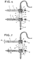
- Fig. 6, 7
- schematisch im nicht vorgespannten Zustand die Seitenansicht von zwei Pedikelschrauben, die über ein elastisches Stützelement und ein Band miteinander verbunden sind;
- Fig. 8
- schematisch im Schnitt ein elastisches Stützelement nach Fig. 6, das zwischen zwei Pedikelschrauben verpresst ist; und
- Fig. 9
- schematisch ein Stützelement aus Fig. 8 im unverpressten Zustand.
- Fig. 1
- schematically a cross section through a lumbar vertebra with a screwed pedicle screw;
- Fig. 2
- schematically the side view of two pedicle screws, which are connected to one another via a support element and a band;
- Fig. 3
- schematically the top view of one of the laterally flattened screw heads from FIG. 2;
- Fig. 4
- schematically the side view of two pedicle screws, which are connected to one another via a support element and a band;
- Fig. 5
- schematically the top view of one of the round screw heads from Fig. 4;
- 6, 7
- schematically in the non-prestressed state, the side view of two pedicle screws which are connected to one another via an elastic support element and a band;
- Fig. 8
- schematically in section an elastic support element according to Figure 6, which is pressed between two pedicle screws. and
- Fig. 9
- schematically shows a support element from FIG. 8 in the unpressed state.
In den Figuren sind Stabilisierungen zwischen zwei in
benachbarten Wirbeln befestigten Pedikelschrauben 2, 3
gezeigt. Zwischen den Schraubenköpfen 6 wird ein auf ein
Band 1 aufgezogenes Stützelement 10, welches wahlweise aus
einem elastischen oder starren Werkstoff besteht, fixiert,
indem das Band an den Schraubenköpfen 6 unter Vorspannung
befestigt wird. Das Band 1 weist einen gegen Scherkräfte
widerstandsfähigen runden Querschnitt auf und besteht aus
elastischem Kunststoff, während das Stützelement 10 einen
druckfesten Körper zur Uebertragung von Druckkräften
zwischen den beiden Schraubenköpfen 6 bildet.
Stützelement 10 und Schraubenkopf 6 liegen mit passenden
Bohrungen 9, 12 allseitig am Band 1 an, um sich
gegenseitig zu zentrieren und stützen sich gegenseitig
auf einer ihnen gemeinsamen um das Band 1 herum
verteilten Stützfläche 13 ab.In the figures there are stabilizations between two in
Pedicle screws 2, 3 attached to adjacent vertebrae
shown. Between the screw heads 6 one on one
In Figur 1 ist eine Pedikelschraube 2 im Sattel 32
zwischen dem Processus costalis 33 und dem Processus
mamillaris 34 so eingeschraubt, dass sie mit ihrer Achse
5 durch das Pedikel 35 den Wirbelkörper 4 zur Verankerung
erreicht. Der Schraubenkopf 6 ist Ausschnitt aus einem
Kugelkörper und liegt im Sattel 32 auf. Der Schraubenkopf
6 ist an zwei gegenüberliegenden Stützflächen 13
abgeflacht und weist einen Durchbruch 7 auf, durch den
ein Band einziehbar ist. Die Pedikelschraube 2, 3 in
benachbarten Wirbelkörpern sind so ausgerichtet, dass
sich die Stützflächen 13 gegenüberliegen, um dazwischen
einen auf das Band 1 aufziehbaren Stützkörper wie in den
Figuren 2, 4, 6, 7, 8 einzubringen.1 shows a
Im Beispiel von Fig. 2, 3 ist im Schraubenkopf 6 der
Pedikelschrauben 2, 3 eine Durchgangsbohrung 12
angebracht, die in einer Bohrung 9 des Stützelements 10
fortgesetzt ist, um das Band 1 aufzunehmen, welches unter
Vorspannung über Schrauben in Gewindebohrungen 37 in
gegenüberliegenden Vertiefungen 31 geklemmt wird. Die
Stützflächen 13 bestehen am Schraubenkopf aus konkaven
Ringflächen 20, die im Fall eines starren Stützkörpers 10
sphärisch 15 mit einem Radius grösser 5 mm sind, während
der Stützkörper eine passende sphärische Gegenfläche 15
aufweist. Am Schraubenkopf sind Aussparungen 36
angebracht, um ein Eindrehwerkzeug oder ein
Halteinstrument ansetzen zu können.In the example of FIGS. 2, 3, the
Im Beispiel von Fig. 4, 5 ist der Schraubenkopf mit
seiner Kugelfläche 30 gleichzeitig Stützfläche für eine
entsprechende konkave Gegenfläche am Stützkörper 10. Die
restlichen Elemente entsprechen denen von Fig. 2, 3.In the example of Fig. 4, 5, the screw head is with
its
Im Beispiel von Fig. 6, 8, 9 besteht das Stützelement aus
einem zylindrischen Hohlkörper 21 aus elastischem
Kunststoff 16, welcher im unbelasteten Zustand durch
jeweils einen umlaufenden radialen Einschnitt 38 von
aussen in zwei zusätzliche Teilstücke 25, 26 unterteilt
ist. Die Teilstücke sind durch einen Hals 24 miteinander
verbunden, wobei der Hals so schwach ist, dass er sich
unter axialer Vorspannung vollständig komprimiert, damit
die Flächen vom Einschnitt 38 zum Tragen kommen. Der
Einschnitt 38 ist nur so breit, dass im unbelasteten
Zustand Teilstücke 25, 26 mit einem Skalpell abtrennbar
sind, um das Stützelement 10 auf die richtige Länge zu
kürzen. Dabei hat sich eine Ausführung mit einem
Mittelteil und zwei Teilstücken 25, 26 als zweckmässig
erwiesen, um vier mögliche Einbaulängen zu erhalten, die
gleichmässig gestuft sind, wenn ein Teilstück 25 die
halbe Länge vom anderen Teilstück 26 aufweist. Es können
daraus vier Längen gewonnen werden, nämlich "mittleres
Teilstück und Teilstücke 25, 26"; "mittleres Teilstück
und Teilstück 26"; "mittleres Teilstück und Teilstück 25"
und "mittleres Teilstück", die eine gleiche Stufung
aufweisen. Die Länge vom Hals 24 darf dabei nicht
mitgerechnet werden. In Fig. 6 ist ein Stützelement mit
einem Teilstück 25 gezeigt. Das Band 1 ist eingezogen,
aber noch unverspannt. Als nächster Schritt würde z.B.
ein Gewindestift 8 an der Pedikelschraube 3 angezogen, um
das Band 1 zu fixieren. Anschliessend wird zwischen der
oberen Pedikelschraube 2 und dem Band 1 eine passende
Vorspannung angebracht und das vorgespannte Band mit dem
oberen Gewindestift 8 fixiert. Die Stützflächen 13 sind
als ebene ringförmige Flächen 14, 17 ausgeführt. Um das
Stützelement besser zu zentrieren, kann diese Ringfläche
am Schraubenkopf als konische Ringfläche 19 ausgeführt
sein, solange sich das
Stützelement 10 im Rahmen seiner Elastizität
hineinverformt.In the example of FIGS. 6, 8, 9, the support element consists of
a cylindrical
Im Beispiel von Fig. 7 sind die Stützflächen am
Schraubenkopf 6 und am Stützelement 10 konisch, wobei der
halbe Konuswinkel 18 mehr als 45° beträgt. Gleichzeitig
weist der Stützkörper zur Mitte hin eine bauchige Form 27
auf, um seine Knickfestigkeit zu erhöhen. Auch in diesem
Fall sind Teilstücke 25, 26 - wie vorher besprochen -
möglich, wenn die radialen Einschnitte auf
Kegelmantelflächen mit ähnlichem Konuswinkel wie
Konuswinkel 18 liegen.In the example of Fig. 7, the support surfaces are on
Die in den Figuren 3 und 5 dargestellten Aussparungen 36
für ein Einschraubwerkzeug dienen nicht nur zum Einziehen
der Pedikelschrauben, welche selbstschneidend mit einem
Gewinde mit konstantem Aussendurchmesser 28 und mit einem
wachsenden Kerndurchmesser 29 ausgeführt sind, sondern
sind auch Ansatzflächen zum Erzeugen eines Gegenmomentes
beim Anziehen der Gewindestifte 8.The
Bei den aufgeführten Beispielen weist das Band 1 einen
gegen Scherkräfte widerstandsfähigen runden Querschnitt 11
auf, wie ihn zum Beispiel umflochtene künstliche
Kreuzbänder besitzen können. Bei einer Biegebelastung
zwischen Schraubenkopf 6 und Stützkörper 10 wird daher ein
Rückstellmoment erzeugt, indem das Band 10 sich dehnt,
während sich der Druck in der Stützfläche 13 einseitig
nach aussen verlagert. Dies hat den Vorteil, dass die
Verstärkung aus einer möglichen elastischen Deformation,
die auch Biegung beinhaltet, immer eine Rückstellung in
die gleiche Ruhelage anstrebt.In the examples listed,
Der als Kugelausschnitt 30 ausgeführte Schraubenkopf
beansprucht nur ein geringes Volumen, was ein tiefes
Einbringen erleichtert, und bietet keine scharfen Kanten
zum Nachbargewebe. Die Gewindestifte 8 sollten nach dem
Einschrauben bündig mit der Kugelfläche 30 abschliessen.The screw head designed as a
Die hier beschriebene Stabilisierung ist nicht auf zwei benachbarte Wirbelkörper mit dazwischenliegender Bandscheibe begrenzt, sondern kann über mehrere aneinander anschliessende Wirbelkörper angebracht werden, um mehrere Segmente zu stabilisieren.The stabilization described here is not two Adjacent vertebral bodies with an intermediate one Intervertebral disc is limited, but can be connected to each other over several subsequent vertebral bodies are attached to several Stabilize segments.
Ebenso können die Stützelemente 10 als leicht gekrümmte
Rohre ausgeführt sein, um der individuellen Lage der
einzelnen Pedikelschrauben besser gerecht zu werden. Die
Stützflächen 13 von zwei Pedikelschrauben 2, 3 zu einem
Stützelement 10 müssen sich dann weniger genau
gegenüberliegen.Likewise, the
Claims (15)
- a stabiliser for adjacent thoracic vertebrae comprising a strap, which is made of elastic synthetic material and has a round cross-section (11) which is resistant to shearing forces, and at least two pedicular screws (2, 3) each of which may be anchored in a different vertebra in the direction of its screw axis (5) and each of which has a screw head (6) with a hole (7) transverse to the screw axis (5), through which may be threaded the strap, and each of which includes a clamping screw (8) to fix the strap (1) transversely to the hole (7) in the direction of the screw axis (5), and also including a support element (10) threaded onto the strap (1),
characterised in that the support element (10) forms a pressure-resistant body for the transmission of compressive forces between two screw heads, the cross-section of the strap bears on all sides in fitting holes (9, 12) in the support element and screw head in order to mutually centre the support element (10) and the screw head (6),
and in that the strap (1) can be prestressed between two adjacent pedicular screws over an extension continuing outside the pedicular screws in order to be able to support the support element (10) and the screw head (6) on a support area (13) which is common to them and is distributed around the strap (1). - a stabilizer according to Claim 1,
characterised in that the common support area (13) consists of an annular surface (14) around the strap (1). - A stabilizer according to Claim 1 or 2,
characterised in that the support element (10) is made of metal of a strong non-metallic material. - A stabilizer according to Claim 3,
characterised in that the common support area (13) is a portion of a spherical surface (15) which has its centre on the side of the screw head (6) or on the side of the support element (10). - A stabilizer according to Claim 3 or 4,
characterised in that a building block system is provided in that several support elements (10) of different lengths may be selected or adjusted. - A stabilizer according to Claim 1 or 2,
characterised in that the support element (10) is made from an elastic synthetic material, preferably of polyurethane. - A stabilizer according to Claim 6,
characterised in that the support area (13) on the screw head (6) is formed by a planar annular surface (17) or by an inwardly conical annular surface (19) with half of the cone angle (18) greater than 45° or by a concave annular surface (20) having a spherical radius greater than 5 mm. - A stabilizer according to Claim 6 or 7,
characterised in that the support element (13) consists of a cylindrical hollow body (21). - A stabilizer according to Claim 8,
characterised in that the cylindrical hollow body (21) is divided by peripheral radial incisions (38) from the outside into cylindrical portions (25, 26) interconnected by a neck (24). - A stabilizer according to Claim 9,
characterised in that the cylindrical hollow body (21) is composed of a central part and two outer portions (25, 26), wherein the outer portions (25, 26) are severable by a scalpel guided in the incision (38) and the one outer portion (25) is half the length of the other outer portion (26), so that by severing none, the one, the other or both portions, four uniformly stepped installation lengths are obtained. - A stabilizer according to Claim 6 or 7,
characterised in that the support element (10) is barrel-shaped (27) in the middle so as to increase its buckling strength. - A stabilizer according to one of Claims 1 to 11,
characterised in that the pedicular screws (2, 3) are tapping screws and have a thread with a constant external diameter (28) and a conically increasing core diameter (29). - A stabilizer according to one of Claims 1 to 12,
characterised in that the screw head (6) consists of a spherical portion (30) to provide application areas which are as small as possible. - A stabilizer according to one of Claims 1 to 13,
characterised in that the screw head (6) has at the hole (7) in the direction of the screw axis (5) and opposite the clamping screw (8) a depression (31) into which may be pressed the strap (1) by the clamping screw. - A stabiliser according to one of Claims 1 to 14,
characterised in that the strap (1), the pedicular screws (2, 3) and the support elements (10) extend over several vertebrae to strengthen an entire section.
Priority Applications (6)
| Application Number | Priority Date | Filing Date | Title |
|---|---|---|---|
| DE59408313T DE59408313D1 (en) | 1994-02-28 | 1994-02-28 | Stabilization of neighboring vertebrae |
| ES94810120T ES2133517T3 (en) | 1994-02-28 | 1994-02-28 | STABILIZER FOR ADJACENT VERTEBRAS. |
| EP94810120A EP0669109B1 (en) | 1994-02-28 | 1994-02-28 | Stabilizer for adjacent vertebrae |
| AT94810120T ATE180402T1 (en) | 1994-02-28 | 1994-02-28 | STABILIZATION OF ADJACENT BACK VERTEBRATE |
| KR1019950000720A KR100354986B1 (en) | 1994-02-28 | 1995-01-18 | Stabilizer of adjacent thoracic vertebrae |
| JP01471095A JP3547514B2 (en) | 1994-02-28 | 1995-01-31 | Stabilizer for adjacent thoracic spine |
Applications Claiming Priority (1)
| Application Number | Priority Date | Filing Date | Title |
|---|---|---|---|
| EP94810120A EP0669109B1 (en) | 1994-02-28 | 1994-02-28 | Stabilizer for adjacent vertebrae |
Publications (2)
| Publication Number | Publication Date |
|---|---|
| EP0669109A1 EP0669109A1 (en) | 1995-08-30 |
| EP0669109B1 true EP0669109B1 (en) | 1999-05-26 |
Family
ID=8218215
Family Applications (1)
| Application Number | Title | Priority Date | Filing Date |
|---|---|---|---|
| EP94810120A Expired - Lifetime EP0669109B1 (en) | 1994-02-28 | 1994-02-28 | Stabilizer for adjacent vertebrae |
Country Status (6)
| Country | Link |
|---|---|
| EP (1) | EP0669109B1 (en) |
| JP (1) | JP3547514B2 (en) |
| KR (1) | KR100354986B1 (en) |
| AT (1) | ATE180402T1 (en) |
| DE (1) | DE59408313D1 (en) |
| ES (1) | ES2133517T3 (en) |
Cited By (155)
| Publication number | Priority date | Publication date | Assignee | Title |
|---|---|---|---|---|
| DE10004712C1 (en) * | 2000-02-03 | 2001-08-09 | Aesculap Ag & Co Kg | Bone plate for bone fracture or fixing adjacent vertebrae has intermediate section between plate-shaped regions secured to fracture sections or vertebrae provided with transverse slits |
| US6290700B1 (en) * | 1997-07-31 | 2001-09-18 | Plus Endoprothetik Ag | Device for stiffening and/or correcting a vertebral column or such like |
| EP1153577A1 (en) | 2000-05-12 | 2001-11-14 | Sulzer Orthopedics Ltd. | Fixation of a bone screw to a bone plate |
| GB2382304A (en) * | 2001-10-10 | 2003-05-28 | Dilip Kumar Sengupta | An assembly for soft stabilisation of vertebral bodies of the spine |
| WO2003047441A1 (en) | 2001-12-07 | 2003-06-12 | Mathys Medizinaltechnik Ag | Damping element |
| EP1364622A2 (en) | 2002-05-21 | 2003-11-26 | Spinelab GmbH | Elastical system for stabilising the spine |
| AU767854B2 (en) * | 1999-12-20 | 2003-11-27 | Synthes Gmbh | Device for the stabilisation of two adjacent verterbral bodies of the spine |
| DE10236691A1 (en) * | 2002-08-09 | 2004-02-26 | Biedermann Motech Gmbh | Dynamic stabilization device for bones, especially for vertebrae |
| DE10320417A1 (en) * | 2003-05-07 | 2004-12-02 | Biedermann Motech Gmbh | Dynamic anchoring device and dynamic stabilization device for bones, in particular for vertebrae, with such an anchoring device |
| DE10348329B3 (en) * | 2003-10-17 | 2005-02-17 | Biedermann Motech Gmbh | Rod-shaped element used in spinal column and accident surgery for connecting two bone-anchoring elements comprises a rigid section and an elastic section that are made in one piece |
| WO2005039454A2 (en) | 2003-10-17 | 2005-05-06 | Biedermann Motech Gmbh | Flexible implant |
| WO2005044123A1 (en) | 2003-11-07 | 2005-05-19 | Biedermann Motech Gmbh | Bone fixing element and stabilising device comprising one such bone fixing element |
| EP1574173A1 (en) | 2004-03-09 | 2005-09-14 | BIEDERMANN MOTECH GmbH | Elastic rod-shaped element for use in spinal or accident surgery and stabilising device comprising such an element |
| DE102004010382A1 (en) * | 2004-03-03 | 2005-09-29 | Biedermann Motech Gmbh | Bone anchoring element for anchoring in a bone or in a vertebra and stabilizing device with such a bone anchoring element |
| WO2006037384A1 (en) | 2004-10-07 | 2006-04-13 | Synthes | Device for dynamic stabilisation of bones or bone fragments, especially vertebrae of the back |
| US7073415B2 (en) | 2003-04-24 | 2006-07-11 | Centerpulse Orthopedics Ltd. | Instrument system for pedicle screws |
| EP1757243A1 (en) | 2005-08-24 | 2007-02-28 | BIEDERMANN MOTECH GmbH | Rod-shaped implant element for the application in spine surgery or trauma surgery and stabilization device with such a rod-shaped implant element |
| US7297146B2 (en) | 2004-01-30 | 2007-11-20 | Warsaw Orthopedic, Inc. | Orthopedic distraction implants and techniques |
| EP1925264A2 (en) | 2003-11-07 | 2008-05-28 | BIEDERMANN MOTECH GmbH | Bone anchoring element |
| DE202008002415U1 (en) | 2008-02-16 | 2008-06-05 | Jenter, Holger, Dipl.-Ing. (FH) | Dynamic stabilization device |
| EP2055251A1 (en) | 2005-12-23 | 2009-05-06 | BIEDERMANN MOTECH GmbH | Bone anchoring element |
| DE102008010358A1 (en) | 2008-02-16 | 2009-08-20 | Jenker, Holger, Dipl.-Ing. (FH) | Dynamic stabilization device |
| US7597694B2 (en) | 2004-01-30 | 2009-10-06 | Warsaw Orthopedic, Inc. | Instruments and methods for minimally invasive spinal stabilization |
| US7611518B2 (en) | 2000-09-18 | 2009-11-03 | Zimmer Gmbh | Pedicle screw for intervertebral support elements |
| US7645294B2 (en) | 2004-03-31 | 2010-01-12 | Depuy Spine, Inc. | Head-to-head connector spinal fixation system |
| US7658752B2 (en) | 2005-06-10 | 2010-02-09 | DePay Spine, Inc. | Posterior dynamic stabilization x-device |
| US7658739B2 (en) | 2005-09-27 | 2010-02-09 | Zimmer Spine, Inc. | Methods and apparatuses for stabilizing the spine through an access device |
| EP2160988A1 (en) | 2008-09-04 | 2010-03-10 | BIEDERMANN MOTECH GmbH | Rod-shaped implant in particular for stabilizing the spinal column and stabilization device including such a rod-shaped implant |
| US7717938B2 (en) | 2004-08-27 | 2010-05-18 | Depuy Spine, Inc. | Dual rod cross connectors and inserter tools |
| US7717939B2 (en) | 2004-03-31 | 2010-05-18 | Depuy Spine, Inc. | Rod attachment for head to head cross connector |
| US7722651B2 (en) | 2005-10-21 | 2010-05-25 | Depuy Spine, Inc. | Adjustable bone screw assembly |
| US7744630B2 (en) | 2005-11-15 | 2010-06-29 | Zimmer Spine, Inc. | Facet repair and stabilization |
| USD620109S1 (en) | 2008-02-05 | 2010-07-20 | Zimmer Spine, Inc. | Surgical installation tool |
| US7763052B2 (en) | 2003-12-05 | 2010-07-27 | N Spine, Inc. | Method and apparatus for flexible fixation of a spine |
| US7766940B2 (en) | 2004-12-30 | 2010-08-03 | Depuy Spine, Inc. | Posterior stabilization system |
| US7799054B2 (en) | 2004-12-30 | 2010-09-21 | Depuy Spine, Inc. | Facet joint replacement |
| US7815665B2 (en) | 2003-09-24 | 2010-10-19 | N Spine, Inc. | Adjustable spinal stabilization system |
| US7815664B2 (en) | 2005-01-04 | 2010-10-19 | Warsaw Orthopedic, Inc. | Systems and methods for spinal stabilization with flexible elements |
| US7862587B2 (en) | 2004-02-27 | 2011-01-04 | Jackson Roger P | Dynamic stabilization assemblies, tool set and method |
| US7879074B2 (en) | 2005-09-27 | 2011-02-01 | Depuy Spine, Inc. | Posterior dynamic stabilization systems and methods |
| US7922725B2 (en) | 2007-04-19 | 2011-04-12 | Zimmer Spine, Inc. | Method and associated instrumentation for installation of spinal dynamic stabilization system |
| CN101605501B (en) * | 2006-12-21 | 2011-04-20 | Ldr医疗公司 | Vertebral support device |
| US7931676B2 (en) | 2007-01-18 | 2011-04-26 | Warsaw Orthopedic, Inc. | Vertebral stabilizer |
| US7942900B2 (en) | 2007-06-05 | 2011-05-17 | Spartek Medical, Inc. | Shaped horizontal rod for dynamic stabilization and motion preservation spinal implantation system and method |
| US7947045B2 (en) | 2006-10-06 | 2011-05-24 | Zimmer Spine, Inc. | Spinal stabilization system with flexible guides |
| US7951170B2 (en) | 2007-05-31 | 2011-05-31 | Jackson Roger P | Dynamic stabilization connecting member with pre-tensioned solid core |
| US7951175B2 (en) | 2005-03-04 | 2011-05-31 | Depuy Spine, Inc. | Instruments and methods for manipulating a vertebra |
| US7951172B2 (en) | 2005-03-04 | 2011-05-31 | Depuy Spine Sarl | Constrained motion bone screw assembly |
| US7963978B2 (en) | 2007-06-05 | 2011-06-21 | Spartek Medical, Inc. | Method for implanting a deflection rod system and customizing the deflection rod system for a particular patient need for dynamic stabilization and motion preservation spinal implantation system |
| US7985244B2 (en) | 2004-09-30 | 2011-07-26 | Depuy Spine, Inc. | Posterior dynamic stabilizer devices |
| US7988710B2 (en) | 2003-09-24 | 2011-08-02 | N Spine, Inc. | Spinal stabilization device |
| US7993375B2 (en) | 2006-12-05 | 2011-08-09 | Spine Wave, Inc. | Dynamic stabilization devices and methods |
| US7993372B2 (en) | 2007-06-05 | 2011-08-09 | Spartek Medical, Inc. | Dynamic stabilization and motion preservation spinal implantation system with a shielded deflection rod system and method |
| US7993370B2 (en) | 2003-09-24 | 2011-08-09 | N Spine, Inc. | Method and apparatus for flexible fixation of a spine |
| US8007518B2 (en) | 2008-02-26 | 2011-08-30 | Spartek Medical, Inc. | Load-sharing component having a deflectable post and method for dynamic stabilization of the spine |
| US8012181B2 (en) | 2008-02-26 | 2011-09-06 | Spartek Medical, Inc. | Modular in-line deflection rod and bone anchor system and method for dynamic stabilization of the spine |
| US8012187B2 (en) | 2002-08-14 | 2011-09-06 | Warsaw Orthopedic, Inc. | Techniques for spinal surgery and attaching constructs to vertebral elements |
| US8012182B2 (en) | 2000-07-25 | 2011-09-06 | Zimmer Spine S.A.S. | Semi-rigid linking piece for stabilizing the spine |
| US8012177B2 (en) | 2007-02-12 | 2011-09-06 | Jackson Roger P | Dynamic stabilization assembly with frusto-conical connection |
| US8016861B2 (en) | 2008-02-26 | 2011-09-13 | Spartek Medical, Inc. | Versatile polyaxial connector assembly and method for dynamic stabilization of the spine |
| US8016832B2 (en) | 2007-05-02 | 2011-09-13 | Zimmer Spine, Inc. | Installation systems for spinal stabilization system and related methods |
| US8021396B2 (en) | 2007-06-05 | 2011-09-20 | Spartek Medical, Inc. | Configurable dynamic spinal rod and method for dynamic stabilization of the spine |
| US8025681B2 (en) | 2006-03-29 | 2011-09-27 | Theken Spine, Llc | Dynamic motion spinal stabilization system |
| US8029544B2 (en) | 2007-01-02 | 2011-10-04 | Zimmer Spine, Inc. | Spine stiffening device |
| US8043337B2 (en) | 2006-06-14 | 2011-10-25 | Spartek Medical, Inc. | Implant system and method to treat degenerative disorders of the spine |
| US8048115B2 (en) | 2007-06-05 | 2011-11-01 | Spartek Medical, Inc. | Surgical tool and method for implantation of a dynamic bone anchor |
| US8052727B2 (en) | 2007-03-23 | 2011-11-08 | Zimmer Gmbh | System and method for insertion of flexible spinal stabilization element |
| US8057517B2 (en) | 2008-02-26 | 2011-11-15 | Spartek Medical, Inc. | Load-sharing component having a deflectable post and centering spring and method for dynamic stabilization of the spine |
| US8057516B2 (en) | 2007-03-21 | 2011-11-15 | Zimmer Spine, Inc. | Spinal stabilization system with rigid and flexible elements |
| US8066739B2 (en) | 2004-02-27 | 2011-11-29 | Jackson Roger P | Tool system for dynamic spinal implants |
| US8083775B2 (en) | 2008-02-26 | 2011-12-27 | Spartek Medical, Inc. | Load-sharing bone anchor having a natural center of rotation and method for dynamic stabilization of the spine |
| US8083772B2 (en) | 2007-06-05 | 2011-12-27 | Spartek Medical, Inc. | Dynamic spinal rod assembly and method for dynamic stabilization of the spine |
| US8092501B2 (en) | 2007-06-05 | 2012-01-10 | Spartek Medical, Inc. | Dynamic spinal rod and method for dynamic stabilization of the spine |
| US8092500B2 (en) | 2007-05-01 | 2012-01-10 | Jackson Roger P | Dynamic stabilization connecting member with floating core, compression spacer and over-mold |
| US8092496B2 (en) | 2004-09-30 | 2012-01-10 | Depuy Spine, Inc. | Methods and devices for posterior stabilization |
| US8097024B2 (en) | 2008-02-26 | 2012-01-17 | Spartek Medical, Inc. | Load-sharing bone anchor having a deflectable post and method for stabilization of the spine |
| US8100915B2 (en) | 2004-02-27 | 2012-01-24 | Jackson Roger P | Orthopedic implant rod reduction tool set and method |
| US8105368B2 (en) | 2005-09-30 | 2012-01-31 | Jackson Roger P | Dynamic stabilization connecting member with slitted core and outer sleeve |
| US8114134B2 (en) | 2007-06-05 | 2012-02-14 | Spartek Medical, Inc. | Spinal prosthesis having a three bar linkage for motion preservation and dynamic stabilization of the spine |
| US8137356B2 (en) | 2008-12-29 | 2012-03-20 | Zimmer Spine, Inc. | Flexible guide for insertion of a vertebral stabilization system |
| US8137355B2 (en) | 2008-12-12 | 2012-03-20 | Zimmer Spine, Inc. | Spinal stabilization installation instrumentation and methods |
| DE102010041264A1 (en) | 2010-09-23 | 2012-03-29 | Aces Gmbh | Dynamic stabilization device for the spine |
| US8157843B2 (en) | 2005-12-23 | 2012-04-17 | Biedermann Motech Gmbh & Co. Kg | Flexible stabilization device for dynamic stabilization of bones or vertebrae |
| US8211155B2 (en) | 2008-02-26 | 2012-07-03 | Spartek Medical, Inc. | Load-sharing bone anchor having a durable compliant member and method for dynamic stabilization of the spine |
| US8257397B2 (en) | 2009-12-02 | 2012-09-04 | Spartek Medical, Inc. | Low profile spinal prosthesis incorporating a bone anchor having a deflectable post and a compound spinal rod |
| US8267979B2 (en) | 2008-02-26 | 2012-09-18 | Spartek Medical, Inc. | Load-sharing bone anchor having a deflectable post and axial spring and method for dynamic stabilization of the spine |
| US8267968B2 (en) | 2009-06-24 | 2012-09-18 | Neuropro Technologies, Inc. | Percutaneous system for dynamic spinal stabilization |
| US8273089B2 (en) | 2004-11-23 | 2012-09-25 | Jackson Roger P | Spinal fixation tool set and method |
| US8282672B2 (en) | 2005-08-29 | 2012-10-09 | Bird Biedermann Ag | Frictional screw-rod connection having an indirect form-locking portion |
| US8292929B2 (en) | 2007-03-16 | 2012-10-23 | Zimmer Spine, Inc. | Dynamic spinal stabilization system and method of using the same |
| US8333792B2 (en) | 2008-02-26 | 2012-12-18 | Spartek Medical, Inc. | Load-sharing bone anchor having a deflectable post and method for dynamic stabilization of the spine |
| US8337536B2 (en) | 2008-02-26 | 2012-12-25 | Spartek Medical, Inc. | Load-sharing bone anchor having a deflectable post with a compliant ring and method for stabilization of the spine |
| US8353932B2 (en) | 2005-09-30 | 2013-01-15 | Jackson Roger P | Polyaxial bone anchor assembly with one-piece closure, pressure insert and plastic elongate member |
| US8357181B2 (en) | 2005-10-27 | 2013-01-22 | Warsaw Orthopedic, Inc. | Intervertebral prosthetic device for spinal stabilization and method of implanting same |
| US8361117B2 (en) | 2006-11-08 | 2013-01-29 | Depuy Spine, Inc. | Spinal cross connectors |
| US8366745B2 (en) | 2007-05-01 | 2013-02-05 | Jackson Roger P | Dynamic stabilization assembly having pre-compressed spacers with differential displacements |
| US8382803B2 (en) | 2010-08-30 | 2013-02-26 | Zimmer Gmbh | Vertebral stabilization transition connector |
| US8394133B2 (en) | 2004-02-27 | 2013-03-12 | Roger P. Jackson | Dynamic fixation assemblies with inner core and outer coil-like member |
| US8430916B1 (en) | 2012-02-07 | 2013-04-30 | Spartek Medical, Inc. | Spinal rod connectors, methods of use, and spinal prosthesis incorporating spinal rod connectors |
| US8444681B2 (en) | 2009-06-15 | 2013-05-21 | Roger P. Jackson | Polyaxial bone anchor with pop-on shank, friction fit retainer and winged insert |
| US8449576B2 (en) | 2006-06-28 | 2013-05-28 | DePuy Synthes Products, LLC | Dynamic fixation system |
| US8465526B2 (en) | 2007-04-30 | 2013-06-18 | Globus Medical, Inc. | Flexible spine stabilization system |
| US8475498B2 (en) | 2007-01-18 | 2013-07-02 | Roger P. Jackson | Dynamic stabilization connecting member with cord connection |
| DE102012202750A1 (en) | 2012-02-22 | 2013-08-22 | Aces Gmbh | Dynamic stabilization device for treating degenerative diseases of spinal column, has support- and mating surfaces formed for clamping by load of spring element, and retaining elements movably mounted against each other in direction |
| DE102012202749A1 (en) | 2012-02-22 | 2013-08-22 | Aces Gmbh | Dynamic stabilization device for bone e.g. spinal column, has deformable regions that are arranged in form of loop, so that sides of loop surround bone in bone quiescent state |
| US8518085B2 (en) | 2010-06-10 | 2013-08-27 | Spartek Medical, Inc. | Adaptive spinal rod and methods for stabilization of the spine |
| US8518080B2 (en) | 2004-12-17 | 2013-08-27 | Zimmer Gmbh | Intervertebral stabilization system |
| US8556938B2 (en) | 2009-06-15 | 2013-10-15 | Roger P. Jackson | Polyaxial bone anchor with non-pivotable retainer and pop-on shank, some with friction fit |
| US8591515B2 (en) | 2004-11-23 | 2013-11-26 | Roger P. Jackson | Spinal fixation tool set and method |
| US8608746B2 (en) | 2008-03-10 | 2013-12-17 | DePuy Synthes Products, LLC | Derotation instrument with reduction functionality |
| US8623057B2 (en) | 2003-09-24 | 2014-01-07 | DePuy Synthes Products, LLC | Spinal stabilization device |
| US8672973B2 (en) | 2005-09-08 | 2014-03-18 | Zimmer Spine Inc. | Facet replacement/spacing and flexible spinal stabilization |
| US8709015B2 (en) | 2008-03-10 | 2014-04-29 | DePuy Synthes Products, LLC | Bilateral vertebral body derotation system |
| US8740945B2 (en) | 2010-04-07 | 2014-06-03 | Zimmer Spine, Inc. | Dynamic stabilization system using polyaxial screws |
| US8771357B2 (en) | 2004-05-04 | 2014-07-08 | Biedermann Technologies Gmbh & Co. Kg | Flexible space holder |
| US8845649B2 (en) | 2004-09-24 | 2014-09-30 | Roger P. Jackson | Spinal fixation tool set and method for rod reduction and fastener insertion |
| US8852239B2 (en) | 2013-02-15 | 2014-10-07 | Roger P Jackson | Sagittal angle screw with integral shank and receiver |
| US8858599B2 (en) | 2004-06-09 | 2014-10-14 | Warsaw Orthopedic, Inc. | Systems and methods for flexible spinal stabilization |
| US8870928B2 (en) | 2002-09-06 | 2014-10-28 | Roger P. Jackson | Helical guide and advancement flange with radially loaded lip |
| US8870925B2 (en) | 2005-09-13 | 2014-10-28 | Bird Biedermann Ag | Dynamic clamping device for spinal implant |
| US8900273B2 (en) | 2005-02-22 | 2014-12-02 | Gmedelaware 2 Llc | Taper-locking fixation system |
| US8906063B2 (en) | 2004-02-17 | 2014-12-09 | Gmedelaware 2 Llc | Spinal facet joint implant |
| US8911478B2 (en) | 2012-11-21 | 2014-12-16 | Roger P. Jackson | Splay control closure for open bone anchor |
| US8911477B2 (en) | 2007-10-23 | 2014-12-16 | Roger P. Jackson | Dynamic stabilization member with end plate support and cable core extension |
| US8926670B2 (en) | 2003-06-18 | 2015-01-06 | Roger P. Jackson | Polyaxial bone screw assembly |
| US8926672B2 (en) | 2004-11-10 | 2015-01-06 | Roger P. Jackson | Splay control closure for open bone anchor |
| US8974499B2 (en) | 2005-02-22 | 2015-03-10 | Stryker Spine | Apparatus and method for dynamic vertebral stabilization |
| US8979904B2 (en) | 2007-05-01 | 2015-03-17 | Roger P Jackson | Connecting member with tensioned cord, low profile rigid sleeve and spacer with torsion control |
| US8992576B2 (en) | 2008-12-17 | 2015-03-31 | DePuy Synthes Products, LLC | Posterior spine dynamic stabilizer |
| US8998959B2 (en) | 2009-06-15 | 2015-04-07 | Roger P Jackson | Polyaxial bone anchors with pop-on shank, fully constrained friction fit retainer and lock and release insert |
| US8998960B2 (en) | 2004-11-10 | 2015-04-07 | Roger P. Jackson | Polyaxial bone screw with helically wound capture connection |
| US9050144B2 (en) | 2007-04-17 | 2015-06-09 | Gmedelaware 2 Llc | System and method for implant anchorage with anti-rotation features |
| US9050139B2 (en) | 2004-02-27 | 2015-06-09 | Roger P. Jackson | Orthopedic implant rod reduction tool set and method |
| US9055979B2 (en) | 2008-12-03 | 2015-06-16 | Zimmer Gmbh | Cord for vertebral fixation having multiple stiffness phases |
| US9101416B2 (en) | 2003-01-24 | 2015-08-11 | DePuy Synthes Products, Inc. | Spinal rod approximator |
| US9107702B2 (en) | 2007-02-06 | 2015-08-18 | Zimmer Gmbh | Central structures spreader for the lumbar spine |
| US9144444B2 (en) | 2003-06-18 | 2015-09-29 | Roger P Jackson | Polyaxial bone anchor with helical capture connection, insert and dual locking assembly |
| US9168069B2 (en) | 2009-06-15 | 2015-10-27 | Roger P. Jackson | Polyaxial bone anchor with pop-on shank and winged insert with lower skirt for engaging a friction fit retainer |
| US9216041B2 (en) | 2009-06-15 | 2015-12-22 | Roger P. Jackson | Spinal connecting members with tensioned cords and rigid sleeves for engaging compression inserts |
| US9226778B2 (en) | 2005-11-17 | 2016-01-05 | Biedermann Technologies Gmbh & Co. Kg | Bone anchoring device |
| US9232968B2 (en) | 2007-12-19 | 2016-01-12 | DePuy Synthes Products, Inc. | Polymeric pedicle rods and methods of manufacturing |
| US9277940B2 (en) | 2008-02-05 | 2016-03-08 | Zimmer Spine, Inc. | System and method for insertion of flexible spinal stabilization element |
| US9308027B2 (en) | 2005-05-27 | 2016-04-12 | Roger P Jackson | Polyaxial bone screw with shank articulation pressure insert and method |
| US9320543B2 (en) | 2009-06-25 | 2016-04-26 | DePuy Synthes Products, Inc. | Posterior dynamic stabilization device having a mobile anchor |
| US9439683B2 (en) | 2007-01-26 | 2016-09-13 | Roger P Jackson | Dynamic stabilization member with molded connection |
| US9445844B2 (en) | 2010-03-24 | 2016-09-20 | DePuy Synthes Products, Inc. | Composite material posterior dynamic stabilization spring rod |
| US9445846B2 (en) | 2005-10-31 | 2016-09-20 | Stryker European Holdings I, Llc | System and method for dynamic vertebral stabilization |
| US9451993B2 (en) | 2014-01-09 | 2016-09-27 | Roger P. Jackson | Bi-radial pop-on cervical bone anchor |
| US9451989B2 (en) | 2007-01-18 | 2016-09-27 | Roger P Jackson | Dynamic stabilization members with elastic and inelastic sections |
| US9480517B2 (en) | 2009-06-15 | 2016-11-01 | Roger P. Jackson | Polyaxial bone anchor with pop-on shank, shank, friction fit retainer, winged insert and low profile edge lock |
| US9526525B2 (en) | 2006-08-22 | 2016-12-27 | Neuropro Technologies, Inc. | Percutaneous system for dynamic spinal stabilization |
| US9566092B2 (en) | 2013-10-29 | 2017-02-14 | Roger P. Jackson | Cervical bone anchor with collet retainer and outer locking sleeve |
| US9597119B2 (en) | 2014-06-04 | 2017-03-21 | Roger P. Jackson | Polyaxial bone anchor with polymer sleeve |
| US10206715B2 (en) | 2001-10-30 | 2019-02-19 | Warsaw Orthopedic, Inc. | Flexible spinal stabilization system and method |
| US10973556B2 (en) | 2008-06-17 | 2021-04-13 | DePuy Synthes Products, Inc. | Adjustable implant assembly |
Families Citing this family (59)
| Publication number | Priority date | Publication date | Assignee | Title |
|---|---|---|---|---|
| DE19738968B4 (en) * | 1997-07-31 | 2012-07-05 | Smith & Nephew Orthopaedics Ag | Device for stiffening and / or correcting a spinal column or the like |
| FR2775583B1 (en) * | 1998-03-04 | 2000-08-11 | Dimso Sa | SYSTEM FOR OSTEOSYNTHESIS OF THE RACHIS WITH LIGAMENT |
| FR2777449B1 (en) * | 1998-04-17 | 2000-09-15 | Sulzer Orthopedics Limited | TENSIONING DEVICE FOR LAYING A SPINAL STABILIZATION SYSTEM |
| EP1188416B1 (en) * | 2000-09-18 | 2005-06-01 | Zimmer GmbH | Pedicle screw for intervertebral support element |
| US8292926B2 (en) * | 2005-09-30 | 2012-10-23 | Jackson Roger P | Dynamic stabilization connecting member with elastic core and outer sleeve |
| US10258382B2 (en) | 2007-01-18 | 2019-04-16 | Roger P. Jackson | Rod-cord dynamic connection assemblies with slidable bone anchor attachment members along the cord |
| US10729469B2 (en) | 2006-01-09 | 2020-08-04 | Roger P. Jackson | Flexible spinal stabilization assembly with spacer having off-axis core member |
| GB0114783D0 (en) | 2001-06-16 | 2001-08-08 | Sengupta Dilip K | A assembly for the stabilisation of vertebral bodies of the spine |
| FR2846222B1 (en) * | 2002-10-24 | 2005-08-26 | Frederic Fortin | MODULAR AND ADJUSTABLE FLEXIBLE VERTEBRAL CONNECTION DEVICE |
| FR2846223B1 (en) * | 2002-10-24 | 2006-04-14 | Frederic Fortin | FLEXIBLE AND MODULAR INTERVERTEBRAL CONNECTION DEVICE HAVING MULTIDIRECTIONAL WORKING ELEMENT |
| US7377923B2 (en) | 2003-05-22 | 2008-05-27 | Alphatec Spine, Inc. | Variable angle spinal screw assembly |
| US8366753B2 (en) | 2003-06-18 | 2013-02-05 | Jackson Roger P | Polyaxial bone screw assembly with fixed retaining structure |
| US7179261B2 (en) | 2003-12-16 | 2007-02-20 | Depuy Spine, Inc. | Percutaneous access devices and bone anchor assemblies |
| US11419642B2 (en) | 2003-12-16 | 2022-08-23 | Medos International Sarl | Percutaneous access devices and bone anchor assemblies |
| US7527638B2 (en) | 2003-12-16 | 2009-05-05 | Depuy Spine, Inc. | Methods and devices for minimally invasive spinal fixation element placement |
| US8029548B2 (en) | 2008-05-05 | 2011-10-04 | Warsaw Orthopedic, Inc. | Flexible spinal stabilization element and system |
| FR2867057B1 (en) * | 2004-03-02 | 2007-06-01 | Spinevision | DYNAMIC BONDING ELEMENT FOR A SPINAL FIXING SYSTEM AND FIXING SYSTEM COMPRISING SUCH A CONNECTING MEMBER |
| WO2005092222A1 (en) * | 2004-03-25 | 2005-10-06 | Un Soon Kim | Multiple rod connecting peidcle screws |
| CA2567833A1 (en) | 2004-05-27 | 2005-12-15 | Depuy Spine, Inc. | Tri-joint implant |
| US8034085B2 (en) | 2004-05-28 | 2011-10-11 | Depuy Spine, Inc. | Non-fusion spinal correction systems and methods |
| US7261738B2 (en) | 2004-06-30 | 2007-08-28 | Depuy Spine, Inc. | C-shaped disc prosthesis |
| US7351261B2 (en) | 2004-06-30 | 2008-04-01 | Depuy Spine, Inc. | Multi-joint implant |
| US8021428B2 (en) | 2004-06-30 | 2011-09-20 | Depuy Spine, Inc. | Ceramic disc prosthesis |
| WO2006005198A1 (en) * | 2004-07-12 | 2006-01-19 | Synthes Gmbh | Device for the dynamic fixation of bones |
| US7854752B2 (en) | 2004-08-09 | 2010-12-21 | Theken Spine, Llc | System and method for dynamic skeletal stabilization |
| WO2006057837A1 (en) | 2004-11-23 | 2006-06-01 | Jackson Roger P | Spinal fixation tool attachment structure |
| US9980753B2 (en) | 2009-06-15 | 2018-05-29 | Roger P Jackson | pivotal anchor with snap-in-place insert having rotation blocking extensions |
| EP1830723A4 (en) * | 2004-12-27 | 2010-03-10 | N Spine Inc | Adjustable spinal stabilization system |
| DE102005005647A1 (en) | 2005-02-08 | 2006-08-17 | Henning Kloss | Pedicle screw for spinal column stabilizing device, has screw head with two opposed oblong hole shaped recesses, and ball unit including recess for accommodating connecting unit and movably mounted in head |
| US20090062868A1 (en) * | 2005-04-04 | 2009-03-05 | Zimmer Gmbh | Pedicle screw |
| US8123783B2 (en) * | 2005-05-06 | 2012-02-28 | Us Spine, Inc. | Pedicle screw-based dynamic posterior stabilization systems and methods |
| US7993376B2 (en) | 2005-09-29 | 2011-08-09 | Depuy Spine, Inc. | Methods of implanting a motion segment repair system |
| WO2007060534A2 (en) * | 2005-11-24 | 2007-05-31 | Giuseppe Calvosa | Modular vertebral stabilizer |
| US8348952B2 (en) | 2006-01-26 | 2013-01-08 | Depuy International Ltd. | System and method for cooling a spinal correction device comprising a shape memory material for corrective spinal surgery |
| US7842072B2 (en) | 2006-03-16 | 2010-11-30 | Zimmer Spine, Inc. | Spinal fixation device with variable stiffness |
| WO2007114834A1 (en) | 2006-04-05 | 2007-10-11 | Dong Myung Jeon | Multi-axial, double locking bone screw assembly |
| US7806913B2 (en) | 2006-08-16 | 2010-10-05 | Depuy Spine, Inc. | Modular multi-level spine stabilization system and method |
| US8425601B2 (en) | 2006-09-11 | 2013-04-23 | Warsaw Orthopedic, Inc. | Spinal stabilization devices and methods of use |
| US8109975B2 (en) * | 2007-01-30 | 2012-02-07 | Warsaw Orthopedic, Inc. | Collar bore configuration for dynamic spinal stabilization assembly |
| US8740944B2 (en) | 2007-02-28 | 2014-06-03 | Warsaw Orthopedic, Inc. | Vertebral stabilizer |
| US8007519B2 (en) | 2007-03-13 | 2011-08-30 | Zimmer Spine, Inc. | Dynamic spinal stabilization system and method of using the same |
| US10383660B2 (en) | 2007-05-01 | 2019-08-20 | Roger P. Jackson | Soft stabilization assemblies with pretensioned cords |
| US8292925B2 (en) | 2007-06-19 | 2012-10-23 | Zimmer Spine, Inc. | Flexible member with variable flexibility for providing dynamic stability to a spine |
| US8252028B2 (en) | 2007-12-19 | 2012-08-28 | Depuy Spine, Inc. | Posterior dynamic stabilization device |
| CA2739997C (en) | 2008-08-01 | 2013-08-13 | Roger P. Jackson | Longitudinal connecting member with sleeved tensioned cords |
| US9668771B2 (en) | 2009-06-15 | 2017-06-06 | Roger P Jackson | Soft stabilization assemblies with off-set connector |
| US11229457B2 (en) | 2009-06-15 | 2022-01-25 | Roger P. Jackson | Pivotal bone anchor assembly with insert tool deployment |
| GB2502449A (en) | 2010-11-02 | 2013-11-27 | Roger P Jackson | Polyaxial bone anchor with pop-on shank and pivotable retainer |
| JP5865479B2 (en) | 2011-03-24 | 2016-02-17 | ロジャー・ピー・ジャクソン | Multiaxial bone anchor with compound joint and pop-mounted shank |
| US8911479B2 (en) | 2012-01-10 | 2014-12-16 | Roger P. Jackson | Multi-start closures for open implants |
| US10058354B2 (en) | 2013-01-28 | 2018-08-28 | Roger P. Jackson | Pivotal bone anchor assembly with frictional shank head seating surfaces |
| FR3004338B1 (en) | 2013-04-15 | 2016-01-08 | Biospine Implants | POLYAXIAL INTERVERTEBRAL DAMPER STABILIZING ONE OR MORE VERTEBRAL SEGMENTS |
| US9717533B2 (en) | 2013-12-12 | 2017-08-01 | Roger P. Jackson | Bone anchor closure pivot-splay control flange form guide and advancement structure |
| AU2015221418B2 (en) | 2014-02-24 | 2019-02-21 | Curtin University Of Technology | A fastener |
| US10758274B1 (en) | 2014-05-02 | 2020-09-01 | Nuvasive, Inc. | Spinal fixation constructs and related methods |
| US10064658B2 (en) | 2014-06-04 | 2018-09-04 | Roger P. Jackson | Polyaxial bone anchor with insert guides |
| CN104306056A (en) * | 2014-07-07 | 2015-01-28 | 吴爱悯 | Jumping type spine dynamic fixing device |
| AU2017233553B2 (en) | 2016-03-18 | 2022-02-03 | Curtin University | An expandable fastener for orthopaedic applications |
| FR3098386A1 (en) | 2019-07-09 | 2021-01-15 | Neuro France Implants | SPINE STABILIZATION SYSTEM |
Family Cites Families (4)
| Publication number | Priority date | Publication date | Assignee | Title |
|---|---|---|---|---|
| FR2625097B1 (en) * | 1987-12-23 | 1990-05-18 | Cote Sarl | INTER-SPINOUS PROSTHESIS COMPOSED OF SEMI-ELASTIC MATERIAL COMPRISING A TRANSFILING EYE AT ITS END AND INTER-SPINOUS PADS |
| FR2633177B1 (en) * | 1988-06-24 | 1991-03-08 | Fabrication Materiel Orthopedi | IMPLANT FOR A SPINAL OSTEOSYNTHESIS DEVICE, ESPECIALLY IN TRAUMATOLOGY |
| FR2676911B1 (en) * | 1991-05-30 | 1998-03-06 | Psi Ste Civile Particuliere | INTERVERTEBRAL STABILIZATION DEVICE WITH SHOCK ABSORBERS. |
| FR2689750B1 (en) * | 1992-04-10 | 1997-01-31 | Eurosurgical | BONE ANCHORING ELEMENT AND SPINAL OSTEOSYNTHESIS DEVICE INCORPORATING SUCH ELEMENTS. |
-
1994
- 1994-02-28 ES ES94810120T patent/ES2133517T3/en not_active Expired - Lifetime
- 1994-02-28 EP EP94810120A patent/EP0669109B1/en not_active Expired - Lifetime
- 1994-02-28 DE DE59408313T patent/DE59408313D1/en not_active Expired - Lifetime
- 1994-02-28 AT AT94810120T patent/ATE180402T1/en active
-
1995
- 1995-01-18 KR KR1019950000720A patent/KR100354986B1/en not_active IP Right Cessation
- 1995-01-31 JP JP01471095A patent/JP3547514B2/en not_active Expired - Lifetime
Non-Patent Citations (1)
| Title |
|---|
| "Restauration cinématique de la précontrainte postérieure du Rachis Lombaire" Publikation von Dr. Jean-Philippe Lemaire * |
Cited By (279)
| Publication number | Priority date | Publication date | Assignee | Title |
|---|---|---|---|---|
| US6290700B1 (en) * | 1997-07-31 | 2001-09-18 | Plus Endoprothetik Ag | Device for stiffening and/or correcting a vertebral column or such like |
| AU767854B2 (en) * | 1999-12-20 | 2003-11-27 | Synthes Gmbh | Device for the stabilisation of two adjacent verterbral bodies of the spine |
| DE10004712C1 (en) * | 2000-02-03 | 2001-08-09 | Aesculap Ag & Co Kg | Bone plate for bone fracture or fixing adjacent vertebrae has intermediate section between plate-shaped regions secured to fracture sections or vertebrae provided with transverse slits |
| EP1153577A1 (en) | 2000-05-12 | 2001-11-14 | Sulzer Orthopedics Ltd. | Fixation of a bone screw to a bone plate |
| US8012182B2 (en) | 2000-07-25 | 2011-09-06 | Zimmer Spine S.A.S. | Semi-rigid linking piece for stabilizing the spine |
| US7611518B2 (en) | 2000-09-18 | 2009-11-03 | Zimmer Gmbh | Pedicle screw for intervertebral support elements |
| US8764802B2 (en) | 2000-09-18 | 2014-07-01 | Zimmer Gmbh | Pedicle screw for intervertebral support elements |
| US7758618B2 (en) | 2000-09-18 | 2010-07-20 | Zimmer Gmbh | Pedicle screw for intervertebral support elements |
| US7967846B2 (en) | 2000-09-18 | 2011-06-28 | Zimmer Gmbh | Pedicle screw for intervertebral support elements |
| US7985248B2 (en) | 2000-09-18 | 2011-07-26 | Zimmer Gmbh | Pedicle screw for intervertebral support elements |
| US7785349B2 (en) | 2000-09-18 | 2010-08-31 | Zimmer Gmbh | Pedicle screw for intervertebral support elements |
| US7846182B2 (en) | 2000-09-18 | 2010-12-07 | Zimmer Gmbh | Pedicle screw for intervertebral support elements |
| GB2382304A (en) * | 2001-10-10 | 2003-05-28 | Dilip Kumar Sengupta | An assembly for soft stabilisation of vertebral bodies of the spine |
| US10206715B2 (en) | 2001-10-30 | 2019-02-19 | Warsaw Orthopedic, Inc. | Flexible spinal stabilization system and method |
| WO2003047441A1 (en) | 2001-12-07 | 2003-06-12 | Mathys Medizinaltechnik Ag | Damping element |
| EP1880684A3 (en) * | 2001-12-07 | 2013-03-06 | Synthes GmbH | Device for stabilisation of adjacent vertebrae with damping element |
| EP1880684A2 (en) | 2001-12-07 | 2008-01-23 | Synthes GmbH | Device for stabilisation of adjacent vertebrae with damping element |
| WO2003047442A1 (en) | 2001-12-07 | 2003-06-12 | Mathys Medizinaltechnik Ag | Damping element and device for stabilisation of adjacent vertebral bodies |
| EP1364622A2 (en) | 2002-05-21 | 2003-11-26 | Spinelab GmbH | Elastical system for stabilising the spine |
| DE10236691B4 (en) * | 2002-08-09 | 2005-12-01 | Biedermann Motech Gmbh | Dynamic stabilization device for bones, in particular for vertebrae |
| US7722649B2 (en) | 2002-08-09 | 2010-05-25 | Biedermann Motech Gmbh | Dynamic stabilization device for bones, in particular for vertebrae |
| DE10236691A1 (en) * | 2002-08-09 | 2004-02-26 | Biedermann Motech Gmbh | Dynamic stabilization device for bones, especially for vertebrae |
| US8012187B2 (en) | 2002-08-14 | 2011-09-06 | Warsaw Orthopedic, Inc. | Techniques for spinal surgery and attaching constructs to vertebral elements |
| US8870928B2 (en) | 2002-09-06 | 2014-10-28 | Roger P. Jackson | Helical guide and advancement flange with radially loaded lip |
| US9101416B2 (en) | 2003-01-24 | 2015-08-11 | DePuy Synthes Products, Inc. | Spinal rod approximator |
| US7073415B2 (en) | 2003-04-24 | 2006-07-11 | Centerpulse Orthopedics Ltd. | Instrument system for pedicle screws |
| US8562652B2 (en) | 2003-05-07 | 2013-10-22 | Biedermann Technologies Gmbh & Co. Kg | Dynamic anchoring device and dynamic stabilization device for vertebrae |
| DE10320417A1 (en) * | 2003-05-07 | 2004-12-02 | Biedermann Motech Gmbh | Dynamic anchoring device and dynamic stabilization device for bones, in particular for vertebrae, with such an anchoring device |
| US8936623B2 (en) | 2003-06-18 | 2015-01-20 | Roger P. Jackson | Polyaxial bone screw assembly |
| US9144444B2 (en) | 2003-06-18 | 2015-09-29 | Roger P Jackson | Polyaxial bone anchor with helical capture connection, insert and dual locking assembly |
| US8926670B2 (en) | 2003-06-18 | 2015-01-06 | Roger P. Jackson | Polyaxial bone screw assembly |
| US8623057B2 (en) | 2003-09-24 | 2014-01-07 | DePuy Synthes Products, LLC | Spinal stabilization device |
| US8968366B2 (en) | 2003-09-24 | 2015-03-03 | DePuy Synthes Products, LLC | Method and apparatus for flexible fixation of a spine |
| US7988710B2 (en) | 2003-09-24 | 2011-08-02 | N Spine, Inc. | Spinal stabilization device |
| US7993370B2 (en) | 2003-09-24 | 2011-08-09 | N Spine, Inc. | Method and apparatus for flexible fixation of a spine |
| US7815665B2 (en) | 2003-09-24 | 2010-10-19 | N Spine, Inc. | Adjustable spinal stabilization system |
| US8979900B2 (en) | 2003-09-24 | 2015-03-17 | DePuy Synthes Products, LLC | Spinal stabilization device |
| US7621912B2 (en) | 2003-10-17 | 2009-11-24 | Biedermann Motech Gmbh | Rod-shaped implant element with flexible section |
| US8721690B2 (en) | 2003-10-17 | 2014-05-13 | Biedermann Technologies GmbH & Co., KG | Rod-shaped implant element with flexible section |
| WO2005039454A2 (en) | 2003-10-17 | 2005-05-06 | Biedermann Motech Gmbh | Flexible implant |
| US9326794B2 (en) | 2003-10-17 | 2016-05-03 | Biedermann Technologies Gmbh & Co. Kg | Rod-shaped implant element with flexible section |
| EP1523949A1 (en) | 2003-10-17 | 2005-04-20 | BIEDERMANN MOTECH GmbH | Surgical rod element, stabilisation device, and method of manufacturing the element |
| DE10348329B3 (en) * | 2003-10-17 | 2005-02-17 | Biedermann Motech Gmbh | Rod-shaped element used in spinal column and accident surgery for connecting two bone-anchoring elements comprises a rigid section and an elastic section that are made in one piece |
| EP2123230A2 (en) | 2003-11-07 | 2009-11-25 | BIEDERMANN MOTECH GmbH | Spring element for a stabiliser device for bones and method for producing same |
| WO2005044123A1 (en) | 2003-11-07 | 2005-05-19 | Biedermann Motech Gmbh | Bone fixing element and stabilising device comprising one such bone fixing element |
| US8632570B2 (en) | 2003-11-07 | 2014-01-21 | Biedermann Technologies Gmbh & Co. Kg | Stabilization device for bones comprising a spring element and manufacturing method for said spring element |
| EP1925264A2 (en) | 2003-11-07 | 2008-05-28 | BIEDERMANN MOTECH GmbH | Bone anchoring element |
| EP2263583A2 (en) | 2003-11-07 | 2010-12-22 | BIEDERMANN MOTECH GmbH | Spring element for a bone stabilisation device, and method for its manufacture |
| US7763052B2 (en) | 2003-12-05 | 2010-07-27 | N Spine, Inc. | Method and apparatus for flexible fixation of a spine |
| US8926700B2 (en) | 2003-12-10 | 2015-01-06 | Gmedelware 2 LLC | Spinal facet joint implant |
| US7297146B2 (en) | 2004-01-30 | 2007-11-20 | Warsaw Orthopedic, Inc. | Orthopedic distraction implants and techniques |
| US8002804B2 (en) | 2004-01-30 | 2011-08-23 | Warsaw Orthopedic, Inc. | Instruments and methods for minimally invasive spinal stabilization |
| US7597694B2 (en) | 2004-01-30 | 2009-10-06 | Warsaw Orthopedic, Inc. | Instruments and methods for minimally invasive spinal stabilization |
| US8142476B2 (en) | 2004-01-30 | 2012-03-27 | Warsaw Orthopedic, Inc. | Orthopedic distraction implants and techniques |
| US8906063B2 (en) | 2004-02-17 | 2014-12-09 | Gmedelaware 2 Llc | Spinal facet joint implant |
| US9216039B2 (en) | 2004-02-27 | 2015-12-22 | Roger P. Jackson | Dynamic spinal stabilization assemblies, tool set and method |
| US8100915B2 (en) | 2004-02-27 | 2012-01-24 | Jackson Roger P | Orthopedic implant rod reduction tool set and method |
| US7862587B2 (en) | 2004-02-27 | 2011-01-04 | Jackson Roger P | Dynamic stabilization assemblies, tool set and method |
| US8394133B2 (en) | 2004-02-27 | 2013-03-12 | Roger P. Jackson | Dynamic fixation assemblies with inner core and outer coil-like member |
| US9055978B2 (en) | 2004-02-27 | 2015-06-16 | Roger P. Jackson | Orthopedic implant rod reduction tool set and method |
| US8066739B2 (en) | 2004-02-27 | 2011-11-29 | Jackson Roger P | Tool system for dynamic spinal implants |
| US9050139B2 (en) | 2004-02-27 | 2015-06-09 | Roger P. Jackson | Orthopedic implant rod reduction tool set and method |
| US8162948B2 (en) | 2004-02-27 | 2012-04-24 | Jackson Roger P | Orthopedic implant rod reduction tool set and method |
| US8377067B2 (en) | 2004-02-27 | 2013-02-19 | Roger P. Jackson | Orthopedic implant rod reduction tool set and method |
| US8894657B2 (en) | 2004-02-27 | 2014-11-25 | Roger P. Jackson | Tool system for dynamic spinal implants |
| US8292892B2 (en) | 2004-02-27 | 2012-10-23 | Jackson Roger P | Orthopedic implant rod reduction tool set and method |
| US7591839B2 (en) | 2004-03-03 | 2009-09-22 | Biedermann Motech Gmbh | Bone anchoring element for anchoring in a bone or vertebra, and stabilization device with such a bone anchoring element |
| DE102004010382B4 (en) * | 2004-03-03 | 2006-04-20 | Biedermann Motech Gmbh | Bone anchoring element for anchoring in a bone or in a vertebra and its use in a stabilizing device |
| DE102004010382A1 (en) * | 2004-03-03 | 2005-09-29 | Biedermann Motech Gmbh | Bone anchoring element for anchoring in a bone or in a vertebra and stabilizing device with such a bone anchoring element |
| US7621940B2 (en) | 2004-03-09 | 2009-11-24 | Biedermann Motech Gmbh | Rod-like element for application in spinal or trauma surgery, and stabilization device with such a rod-like element |
| DE102004011685A1 (en) * | 2004-03-09 | 2005-09-29 | Biedermann Motech Gmbh | Spine supporting element, comprising spiraled grooves at outer surface and three plain areas |
| EP1574173A1 (en) | 2004-03-09 | 2005-09-14 | BIEDERMANN MOTECH GmbH | Elastic rod-shaped element for use in spinal or accident surgery and stabilising device comprising such an element |
| US7717939B2 (en) | 2004-03-31 | 2010-05-18 | Depuy Spine, Inc. | Rod attachment for head to head cross connector |
| US7645294B2 (en) | 2004-03-31 | 2010-01-12 | Depuy Spine, Inc. | Head-to-head connector spinal fixation system |
| US8771357B2 (en) | 2004-05-04 | 2014-07-08 | Biedermann Technologies Gmbh & Co. Kg | Flexible space holder |
| US8858599B2 (en) | 2004-06-09 | 2014-10-14 | Warsaw Orthopedic, Inc. | Systems and methods for flexible spinal stabilization |
| US8372119B2 (en) | 2004-08-27 | 2013-02-12 | Depuy Spine, Inc. | Dual rod cross connectors and inserter tools |
| US7717938B2 (en) | 2004-08-27 | 2010-05-18 | Depuy Spine, Inc. | Dual rod cross connectors and inserter tools |
| US8845649B2 (en) | 2004-09-24 | 2014-09-30 | Roger P. Jackson | Spinal fixation tool set and method for rod reduction and fastener insertion |
| US7985244B2 (en) | 2004-09-30 | 2011-07-26 | Depuy Spine, Inc. | Posterior dynamic stabilizer devices |
| US8092496B2 (en) | 2004-09-30 | 2012-01-10 | Depuy Spine, Inc. | Methods and devices for posterior stabilization |
| US7867256B2 (en) | 2004-10-07 | 2011-01-11 | Synthes Usa, Llc | Device for dynamic stabilization of bones or bone fragments |
| WO2006037384A1 (en) | 2004-10-07 | 2006-04-13 | Synthes | Device for dynamic stabilisation of bones or bone fragments, especially vertebrae of the back |
| US8926672B2 (en) | 2004-11-10 | 2015-01-06 | Roger P. Jackson | Splay control closure for open bone anchor |
| US8998960B2 (en) | 2004-11-10 | 2015-04-07 | Roger P. Jackson | Polyaxial bone screw with helically wound capture connection |
| US9522021B2 (en) | 2004-11-23 | 2016-12-20 | Roger P. Jackson | Polyaxial bone anchor with retainer with notch for mono-axial motion |
| US8273089B2 (en) | 2004-11-23 | 2012-09-25 | Jackson Roger P | Spinal fixation tool set and method |
| US8591515B2 (en) | 2004-11-23 | 2013-11-26 | Roger P. Jackson | Spinal fixation tool set and method |
| US8613757B2 (en) | 2004-12-17 | 2013-12-24 | Zimmer Gmbh | Intervertebral stabilization system |
| US8518080B2 (en) | 2004-12-17 | 2013-08-27 | Zimmer Gmbh | Intervertebral stabilization system |
| US8523905B2 (en) | 2004-12-17 | 2013-09-03 | Zimmer Gmbh | Intervertebral stabilization system |
| US8608778B2 (en) | 2004-12-17 | 2013-12-17 | Zimmer Gmbh | Intervertebral stabilization system |
| US7766940B2 (en) | 2004-12-30 | 2010-08-03 | Depuy Spine, Inc. | Posterior stabilization system |
| US7799054B2 (en) | 2004-12-30 | 2010-09-21 | Depuy Spine, Inc. | Facet joint replacement |
| US7896906B2 (en) | 2004-12-30 | 2011-03-01 | Depuy Spine, Inc. | Artificial facet joint |
| US8414620B2 (en) | 2005-01-04 | 2013-04-09 | Warsaw Orthopedic, Inc. | Systems and methods for spinal stabilization with flexible elements |
| US8888817B2 (en) | 2005-01-04 | 2014-11-18 | Warsaw Orthopedic, Inc. | Systems and methods for spinal stabilization with flexible elements |
| US7815664B2 (en) | 2005-01-04 | 2010-10-19 | Warsaw Orthopedic, Inc. | Systems and methods for spinal stabilization with flexible elements |
| US8900273B2 (en) | 2005-02-22 | 2014-12-02 | Gmedelaware 2 Llc | Taper-locking fixation system |
| US9486244B2 (en) | 2005-02-22 | 2016-11-08 | Stryker European Holdings I, Llc | Apparatus and method for dynamic vertebral stabilization |
| US8974499B2 (en) | 2005-02-22 | 2015-03-10 | Stryker Spine | Apparatus and method for dynamic vertebral stabilization |
| US8007516B2 (en) | 2005-03-04 | 2011-08-30 | Depuy Spine, Inc. | Instruments and methods for manipulating vertebra |
| US11849978B2 (en) | 2005-03-04 | 2023-12-26 | Medos International Sarl | Constrained motion bone screw assembly |
| US8709044B2 (en) | 2005-03-04 | 2014-04-29 | DePuy Synthes Products, LLC | Instruments and methods for manipulating vertebra |
| US7951175B2 (en) | 2005-03-04 | 2011-05-31 | Depuy Spine, Inc. | Instruments and methods for manipulating a vertebra |
| US9795416B2 (en) | 2005-03-04 | 2017-10-24 | Medos International Sárl | Constrained motion bone screw assembly |
| US10172648B2 (en) | 2005-03-04 | 2019-01-08 | Medos International Sarl | Constrained motion bone screw assembly |
| US7951168B2 (en) | 2005-03-04 | 2011-05-31 | Depuy Spine, Inc. | Instruments and methods for manipulating vertebra |
| US7951172B2 (en) | 2005-03-04 | 2011-05-31 | Depuy Spine Sarl | Constrained motion bone screw assembly |
| US9095379B2 (en) | 2005-03-04 | 2015-08-04 | Medos International Sarl | Constrained motion bone screw assembly |
| US11000315B2 (en) | 2005-03-04 | 2021-05-11 | Medos International Sarl | Constrained motion bone screw assembly |
| US9308027B2 (en) | 2005-05-27 | 2016-04-12 | Roger P Jackson | Polyaxial bone screw with shank articulation pressure insert and method |
| US7658752B2 (en) | 2005-06-10 | 2010-02-09 | DePay Spine, Inc. | Posterior dynamic stabilization x-device |
| US7951169B2 (en) | 2005-06-10 | 2011-05-31 | Depuy Spine, Inc. | Posterior dynamic stabilization cross connectors |
| US7967844B2 (en) | 2005-06-10 | 2011-06-28 | Depuy Spine, Inc. | Multi-level posterior dynamic stabilization systems and methods |
| US7763051B2 (en) | 2005-06-10 | 2010-07-27 | Depuy Spine, Inc. | Posterior dynamic stabilization systems and methods |
| US7695496B2 (en) | 2005-06-10 | 2010-04-13 | Depuy Spine, Inc. | Posterior dynamic stabilization Y-device |
| US8491637B2 (en) | 2005-08-24 | 2013-07-23 | Biedermann Technologies GmbH & Co., KG | Rod-shaped implant element for the application in spine surgery or trauma surgery and stabilization device with such a rod-shaped implant element |
| US9492202B2 (en) | 2005-08-24 | 2016-11-15 | Biedermann Technologies Gmbh & Co. Kg | Rod-shaped implant element for the application in spine surgery or trauma surgery and stabilization device with such a rod-shaped implant element |
| EP1757243A1 (en) | 2005-08-24 | 2007-02-28 | BIEDERMANN MOTECH GmbH | Rod-shaped implant element for the application in spine surgery or trauma surgery and stabilization device with such a rod-shaped implant element |
| US8282672B2 (en) | 2005-08-29 | 2012-10-09 | Bird Biedermann Ag | Frictional screw-rod connection having an indirect form-locking portion |
| US8672973B2 (en) | 2005-09-08 | 2014-03-18 | Zimmer Spine Inc. | Facet replacement/spacing and flexible spinal stabilization |
| US8870925B2 (en) | 2005-09-13 | 2014-10-28 | Bird Biedermann Ag | Dynamic clamping device for spinal implant |
| US7658739B2 (en) | 2005-09-27 | 2010-02-09 | Zimmer Spine, Inc. | Methods and apparatuses for stabilizing the spine through an access device |
| US8016828B2 (en) | 2005-09-27 | 2011-09-13 | Zimmer Spine, Inc. | Methods and apparatuses for stabilizing the spine through an access device |
| US7879074B2 (en) | 2005-09-27 | 2011-02-01 | Depuy Spine, Inc. | Posterior dynamic stabilization systems and methods |
| US8353932B2 (en) | 2005-09-30 | 2013-01-15 | Jackson Roger P | Polyaxial bone anchor assembly with one-piece closure, pressure insert and plastic elongate member |
| US8696711B2 (en) | 2005-09-30 | 2014-04-15 | Roger P. Jackson | Polyaxial bone anchor assembly with one-piece closure, pressure insert and plastic elongate member |
| US8105368B2 (en) | 2005-09-30 | 2012-01-31 | Jackson Roger P | Dynamic stabilization connecting member with slitted core and outer sleeve |
| US8613760B2 (en) | 2005-09-30 | 2013-12-24 | Roger P. Jackson | Dynamic stabilization connecting member with slitted core and outer sleeve |
| US7951174B2 (en) | 2005-10-21 | 2011-05-31 | Depuy Spine, Inc. | Adjustable bone screw assembly |
| US8845700B2 (en) | 2005-10-21 | 2014-09-30 | DePuy Synthes Products, LLC. | Adjustable bone screw assembly |
| US8603144B2 (en) | 2005-10-21 | 2013-12-10 | DePuy Synthes Products, LLC | Adjustable bone screw assembly |
| US7722651B2 (en) | 2005-10-21 | 2010-05-25 | Depuy Spine, Inc. | Adjustable bone screw assembly |
| US8357181B2 (en) | 2005-10-27 | 2013-01-22 | Warsaw Orthopedic, Inc. | Intervertebral prosthetic device for spinal stabilization and method of implanting same |
| US9445846B2 (en) | 2005-10-31 | 2016-09-20 | Stryker European Holdings I, Llc | System and method for dynamic vertebral stabilization |
| US7744630B2 (en) | 2005-11-15 | 2010-06-29 | Zimmer Spine, Inc. | Facet repair and stabilization |
| US9226778B2 (en) | 2005-11-17 | 2016-01-05 | Biedermann Technologies Gmbh & Co. Kg | Bone anchoring device |
| US8157843B2 (en) | 2005-12-23 | 2012-04-17 | Biedermann Motech Gmbh & Co. Kg | Flexible stabilization device for dynamic stabilization of bones or vertebrae |
| EP2055251A1 (en) | 2005-12-23 | 2009-05-06 | BIEDERMANN MOTECH GmbH | Bone anchoring element |
| US8979902B2 (en) | 2005-12-23 | 2015-03-17 | Biedermann Technologies Gmbh & Co. Kg | Dynamic stabilization device for bones or vertebrae |
| US8192468B2 (en) | 2005-12-23 | 2012-06-05 | Biedermann Technologies Gmbh & Co. Kg | Dynamic stabilization device for bones or vertebrae |
| US8025681B2 (en) | 2006-03-29 | 2011-09-27 | Theken Spine, Llc | Dynamic motion spinal stabilization system |
| US8043337B2 (en) | 2006-06-14 | 2011-10-25 | Spartek Medical, Inc. | Implant system and method to treat degenerative disorders of the spine |
| US8172882B2 (en) | 2006-06-14 | 2012-05-08 | Spartek Medical, Inc. | Implant system and method to treat degenerative disorders of the spine |
| US8449576B2 (en) | 2006-06-28 | 2013-05-28 | DePuy Synthes Products, LLC | Dynamic fixation system |
| US9526525B2 (en) | 2006-08-22 | 2016-12-27 | Neuropro Technologies, Inc. | Percutaneous system for dynamic spinal stabilization |
| US7947045B2 (en) | 2006-10-06 | 2011-05-24 | Zimmer Spine, Inc. | Spinal stabilization system with flexible guides |
| US8361117B2 (en) | 2006-11-08 | 2013-01-29 | Depuy Spine, Inc. | Spinal cross connectors |
| US8425571B2 (en) | 2006-12-05 | 2013-04-23 | Spine Wave, Inc. | Method for stabilizing a motion segment of the spine of a patient |
| US7993375B2 (en) | 2006-12-05 | 2011-08-09 | Spine Wave, Inc. | Dynamic stabilization devices and methods |
| CN101605501B (en) * | 2006-12-21 | 2011-04-20 | Ldr医疗公司 | Vertebral support device |
| US8029544B2 (en) | 2007-01-02 | 2011-10-04 | Zimmer Spine, Inc. | Spine stiffening device |
| US8206422B2 (en) | 2007-01-02 | 2012-06-26 | Zimmer Spine, Inc. | Spine stiffening device and associated method |
| US7931676B2 (en) | 2007-01-18 | 2011-04-26 | Warsaw Orthopedic, Inc. | Vertebral stabilizer |
| US9451989B2 (en) | 2007-01-18 | 2016-09-27 | Roger P Jackson | Dynamic stabilization members with elastic and inelastic sections |
| US8475498B2 (en) | 2007-01-18 | 2013-07-02 | Roger P. Jackson | Dynamic stabilization connecting member with cord connection |
| US9439683B2 (en) | 2007-01-26 | 2016-09-13 | Roger P Jackson | Dynamic stabilization member with molded connection |
| US9107702B2 (en) | 2007-02-06 | 2015-08-18 | Zimmer Gmbh | Central structures spreader for the lumbar spine |
| US8012177B2 (en) | 2007-02-12 | 2011-09-06 | Jackson Roger P | Dynamic stabilization assembly with frusto-conical connection |
| US8506599B2 (en) | 2007-02-12 | 2013-08-13 | Roger P. Jackson | Dynamic stabilization assembly with frusto-conical connection |
| US8292929B2 (en) | 2007-03-16 | 2012-10-23 | Zimmer Spine, Inc. | Dynamic spinal stabilization system and method of using the same |
| US9888944B2 (en) | 2007-03-21 | 2018-02-13 | Zimmer Spine, Inc. | Spinal stabilization system with rigid and flexible elements |
| US10631898B2 (en) | 2007-03-21 | 2020-04-28 | Zimmer Spine, Inc. | Spinal stabilization system with rigid and flexible elements |
| US9034018B2 (en) | 2007-03-21 | 2015-05-19 | Zimmer Spine, Inc. | Spinal stabilization system with rigid and flexible elements |
| US8057516B2 (en) | 2007-03-21 | 2011-11-15 | Zimmer Spine, Inc. | Spinal stabilization system with rigid and flexible elements |
| US8052727B2 (en) | 2007-03-23 | 2011-11-08 | Zimmer Gmbh | System and method for insertion of flexible spinal stabilization element |
| US8603146B2 (en) | 2007-03-23 | 2013-12-10 | Zimmer Gmbh | System and method for insertion of flexible spinal stabilization element |
| US9050144B2 (en) | 2007-04-17 | 2015-06-09 | Gmedelaware 2 Llc | System and method for implant anchorage with anti-rotation features |
| US7922725B2 (en) | 2007-04-19 | 2011-04-12 | Zimmer Spine, Inc. | Method and associated instrumentation for installation of spinal dynamic stabilization system |
| US8465526B2 (en) | 2007-04-30 | 2013-06-18 | Globus Medical, Inc. | Flexible spine stabilization system |
| US8366745B2 (en) | 2007-05-01 | 2013-02-05 | Jackson Roger P | Dynamic stabilization assembly having pre-compressed spacers with differential displacements |
| US8092500B2 (en) | 2007-05-01 | 2012-01-10 | Jackson Roger P | Dynamic stabilization connecting member with floating core, compression spacer and over-mold |
| US8979904B2 (en) | 2007-05-01 | 2015-03-17 | Roger P Jackson | Connecting member with tensioned cord, low profile rigid sleeve and spacer with torsion control |
| US8016832B2 (en) | 2007-05-02 | 2011-09-13 | Zimmer Spine, Inc. | Installation systems for spinal stabilization system and related methods |
| US8246659B2 (en) | 2007-05-02 | 2012-08-21 | Zimmer Spine, Inc. | Installation systems for spinal stabilization system and related methods |
| US7951170B2 (en) | 2007-05-31 | 2011-05-31 | Jackson Roger P | Dynamic stabilization connecting member with pre-tensioned solid core |
| US7942900B2 (en) | 2007-06-05 | 2011-05-17 | Spartek Medical, Inc. | Shaped horizontal rod for dynamic stabilization and motion preservation spinal implantation system and method |
| US8083772B2 (en) | 2007-06-05 | 2011-12-27 | Spartek Medical, Inc. | Dynamic spinal rod assembly and method for dynamic stabilization of the spine |
| US8109970B2 (en) | 2007-06-05 | 2012-02-07 | Spartek Medical, Inc. | Deflection rod system with a deflection contouring shield for a spine implant and method |
| US8114130B2 (en) | 2007-06-05 | 2012-02-14 | Spartek Medical, Inc. | Deflection rod system for spine implant with end connectors and method |
| US8142480B2 (en) | 2007-06-05 | 2012-03-27 | Spartek Medical, Inc. | Dynamic stabilization and motion preservation spinal implantation system with horizontal deflection rod and articulating vertical rods |
| US8147520B2 (en) | 2007-06-05 | 2012-04-03 | Spartek Medical, Inc. | Horizontally loaded dynamic stabilization and motion preservation spinal implantation system and method |
| US8192469B2 (en) | 2007-06-05 | 2012-06-05 | Spartek Medical, Inc. | Dynamic stabilization and motion preservation spinal implantation system and method with a deflection rod |
| US8070774B2 (en) | 2007-06-05 | 2011-12-06 | Spartek Medical, Inc. | Reinforced bone anchor for a dynamic stabilization and motion preservation spinal implantation system and method |
| US8080039B2 (en) | 2007-06-05 | 2011-12-20 | Spartek Medical, Inc. | Anchor system for a spine implantation system that can move about three axes |
| US8114134B2 (en) | 2007-06-05 | 2012-02-14 | Spartek Medical, Inc. | Spinal prosthesis having a three bar linkage for motion preservation and dynamic stabilization of the spine |
| US8162987B2 (en) | 2007-06-05 | 2012-04-24 | Spartek Medical, Inc. | Modular spine treatment kit for dynamic stabilization and motion preservation of the spine |
| US8052722B2 (en) | 2007-06-05 | 2011-11-08 | Spartek Medical, Inc. | Dual deflection rod system for a dynamic stabilization and motion preservation spinal implantation system and method |
| US8070780B2 (en) | 2007-06-05 | 2011-12-06 | Spartek Medical, Inc. | Bone anchor with a yoke-shaped anchor head for a dynamic stabilization and motion preservation spinal implantation system and method |
| US8070776B2 (en) | 2007-06-05 | 2011-12-06 | Spartek Medical, Inc. | Deflection rod system for use with a vertebral fusion implant for dynamic stabilization and motion preservation spinal implantation system and method |
| US8177815B2 (en) | 2007-06-05 | 2012-05-15 | Spartek Medical, Inc. | Super-elastic deflection rod for a dynamic stabilization and motion preservation spinal implantation system and method |
| US8070775B2 (en) | 2007-06-05 | 2011-12-06 | Spartek Medical, Inc. | Deflection rod system for a dynamic stabilization and motion preservation spinal implantation system and method |
| US8568451B2 (en) | 2007-06-05 | 2013-10-29 | Spartek Medical, Inc. | Bone anchor for receiving a rod for stabilization and motion preservation spinal implantation system and method |
| US8066747B2 (en) | 2007-06-05 | 2011-11-29 | Spartek Medical, Inc. | Implantation method for a dynamic stabilization and motion preservation spinal implantation system and method |
| US8092501B2 (en) | 2007-06-05 | 2012-01-10 | Spartek Medical, Inc. | Dynamic spinal rod and method for dynamic stabilization of the spine |
| US8182516B2 (en) | 2007-06-05 | 2012-05-22 | Spartek Medical, Inc. | Rod capture mechanism for dynamic stabilization and motion preservation spinal implantation system and method |
| US8012175B2 (en) | 2007-06-05 | 2011-09-06 | Spartek Medical, Inc. | Multi-directional deflection profile for a dynamic stabilization and motion preservation spinal implantation system and method |
| US8002803B2 (en) | 2007-06-05 | 2011-08-23 | Spartek Medical, Inc. | Deflection rod system for a spine implant including an inner rod and an outer shell and method |
| US8182515B2 (en) | 2007-06-05 | 2012-05-22 | Spartek Medical, Inc. | Dynamic stabilization and motion preservation spinal implantation system and method |
| US8057514B2 (en) | 2007-06-05 | 2011-11-15 | Spartek Medical, Inc. | Deflection rod system dimensioned for deflection to a load characteristic for dynamic stabilization and motion preservation spinal implantation system and method |
| US8105359B2 (en) | 2007-06-05 | 2012-01-31 | Spartek Medical, Inc. | Deflection rod system for a dynamic stabilization and motion preservation spinal implantation system and method |
| US8021396B2 (en) | 2007-06-05 | 2011-09-20 | Spartek Medical, Inc. | Configurable dynamic spinal rod and method for dynamic stabilization of the spine |
| US8172881B2 (en) | 2007-06-05 | 2012-05-08 | Spartek Medical, Inc. | Dynamic stabilization and motion preservation spinal implantation system and method with a deflection rod mounted in close proximity to a mounting rod |
| US8052721B2 (en) | 2007-06-05 | 2011-11-08 | Spartek Medical, Inc. | Multi-dimensional horizontal rod for a dynamic stabilization and motion preservation spinal implantation system and method |
| US8118842B2 (en) | 2007-06-05 | 2012-02-21 | Spartek Medical, Inc. | Multi-level dynamic stabilization and motion preservation spinal implantation system and method |
| US8048122B2 (en) | 2007-06-05 | 2011-11-01 | Spartek Medical, Inc. | Spine implant with a dual deflection rod system including a deflection limiting sheild associated with a bone screw and method |
| US8048113B2 (en) | 2007-06-05 | 2011-11-01 | Spartek Medical, Inc. | Deflection rod system with a non-linear deflection to load characteristic for a dynamic stabilization and motion preservation spinal implantation system and method |
| US7963978B2 (en) | 2007-06-05 | 2011-06-21 | Spartek Medical, Inc. | Method for implanting a deflection rod system and customizing the deflection rod system for a particular patient need for dynamic stabilization and motion preservation spinal implantation system |
| US8048115B2 (en) | 2007-06-05 | 2011-11-01 | Spartek Medical, Inc. | Surgical tool and method for implantation of a dynamic bone anchor |
| US8048121B2 (en) | 2007-06-05 | 2011-11-01 | Spartek Medical, Inc. | Spine implant with a defelction rod system anchored to a bone anchor and method |
| US7985243B2 (en) | 2007-06-05 | 2011-07-26 | Spartek Medical, Inc. | Deflection rod system with mount for a dynamic stabilization and motion preservation spinal implantation system and method |
| US8211150B2 (en) | 2007-06-05 | 2012-07-03 | Spartek Medical, Inc. | Dynamic stabilization and motion preservation spinal implantation system and method |
| US7993372B2 (en) | 2007-06-05 | 2011-08-09 | Spartek Medical, Inc. | Dynamic stabilization and motion preservation spinal implantation system with a shielded deflection rod system and method |
| US8002800B2 (en) | 2007-06-05 | 2011-08-23 | Spartek Medical, Inc. | Horizontal rod with a mounting platform for a dynamic stabilization and motion preservation spinal implantation system and method |
| US8048128B2 (en) | 2007-06-05 | 2011-11-01 | Spartek Medical, Inc. | Revision system and method for a dynamic stabilization and motion preservation spinal implantation system and method |
| US8048123B2 (en) | 2007-06-05 | 2011-11-01 | Spartek Medical, Inc. | Spine implant with a deflection rod system and connecting linkages and method |
| US8317836B2 (en) | 2007-06-05 | 2012-11-27 | Spartek Medical, Inc. | Bone anchor for receiving a rod for stabilization and motion preservation spinal implantation system and method |
| US8298267B2 (en) | 2007-06-05 | 2012-10-30 | Spartek Medical, Inc. | Spine implant with a deflection rod system including a deflection limiting shield associated with a bone screw and method |
| US8105356B2 (en) | 2007-06-05 | 2012-01-31 | Spartek Medical, Inc. | Bone anchor with a curved mounting element for a dynamic stabilization and motion preservation spinal implantation system and method |
| US8911477B2 (en) | 2007-10-23 | 2014-12-16 | Roger P. Jackson | Dynamic stabilization member with end plate support and cable core extension |
| US9232968B2 (en) | 2007-12-19 | 2016-01-12 | DePuy Synthes Products, Inc. | Polymeric pedicle rods and methods of manufacturing |
| US9277940B2 (en) | 2008-02-05 | 2016-03-08 | Zimmer Spine, Inc. | System and method for insertion of flexible spinal stabilization element |
| USD620109S1 (en) | 2008-02-05 | 2010-07-20 | Zimmer Spine, Inc. | Surgical installation tool |
| DE202008002415U1 (en) | 2008-02-16 | 2008-06-05 | Jenter, Holger, Dipl.-Ing. (FH) | Dynamic stabilization device |
| DE102008010358A1 (en) | 2008-02-16 | 2009-08-20 | Jenker, Holger, Dipl.-Ing. (FH) | Dynamic stabilization device |
| US8012181B2 (en) | 2008-02-26 | 2011-09-06 | Spartek Medical, Inc. | Modular in-line deflection rod and bone anchor system and method for dynamic stabilization of the spine |
| US8057517B2 (en) | 2008-02-26 | 2011-11-15 | Spartek Medical, Inc. | Load-sharing component having a deflectable post and centering spring and method for dynamic stabilization of the spine |
| US8007518B2 (en) | 2008-02-26 | 2011-08-30 | Spartek Medical, Inc. | Load-sharing component having a deflectable post and method for dynamic stabilization of the spine |
| US8016861B2 (en) | 2008-02-26 | 2011-09-13 | Spartek Medical, Inc. | Versatile polyaxial connector assembly and method for dynamic stabilization of the spine |
| US8337536B2 (en) | 2008-02-26 | 2012-12-25 | Spartek Medical, Inc. | Load-sharing bone anchor having a deflectable post with a compliant ring and method for stabilization of the spine |
| US8211155B2 (en) | 2008-02-26 | 2012-07-03 | Spartek Medical, Inc. | Load-sharing bone anchor having a durable compliant member and method for dynamic stabilization of the spine |
| US8267979B2 (en) | 2008-02-26 | 2012-09-18 | Spartek Medical, Inc. | Load-sharing bone anchor having a deflectable post and axial spring and method for dynamic stabilization of the spine |
| US8097024B2 (en) | 2008-02-26 | 2012-01-17 | Spartek Medical, Inc. | Load-sharing bone anchor having a deflectable post and method for stabilization of the spine |
| US8083775B2 (en) | 2008-02-26 | 2011-12-27 | Spartek Medical, Inc. | Load-sharing bone anchor having a natural center of rotation and method for dynamic stabilization of the spine |
| US8048125B2 (en) | 2008-02-26 | 2011-11-01 | Spartek Medical, Inc. | Versatile offset polyaxial connector and method for dynamic stabilization of the spine |
| US8057515B2 (en) | 2008-02-26 | 2011-11-15 | Spartek Medical, Inc. | Load-sharing anchor having a deflectable post and centering spring and method for dynamic stabilization of the spine |
| US8333792B2 (en) | 2008-02-26 | 2012-12-18 | Spartek Medical, Inc. | Load-sharing bone anchor having a deflectable post and method for dynamic stabilization of the spine |
| US8709015B2 (en) | 2008-03-10 | 2014-04-29 | DePuy Synthes Products, LLC | Bilateral vertebral body derotation system |
| US8608746B2 (en) | 2008-03-10 | 2013-12-17 | DePuy Synthes Products, LLC | Derotation instrument with reduction functionality |
| US9326798B2 (en) | 2008-03-10 | 2016-05-03 | DePuy Synthes Products, Inc. | Derotation instrument with reduction functionality |
| US10973556B2 (en) | 2008-06-17 | 2021-04-13 | DePuy Synthes Products, Inc. | Adjustable implant assembly |
| US9451988B2 (en) | 2008-09-04 | 2016-09-27 | Biedermann Technologies Gmbh & Co. Kg | Rod-shaped implant in particular for stabilizing the spinal column and stabilization device including such a rod-shaped implant |
| EP2160988A1 (en) | 2008-09-04 | 2010-03-10 | BIEDERMANN MOTECH GmbH | Rod-shaped implant in particular for stabilizing the spinal column and stabilization device including such a rod-shaped implant |
| US8216281B2 (en) | 2008-12-03 | 2012-07-10 | Spartek Medical, Inc. | Low profile spinal prosthesis incorporating a bone anchor having a deflectable post and a compound spinal rod |
| US9055979B2 (en) | 2008-12-03 | 2015-06-16 | Zimmer Gmbh | Cord for vertebral fixation having multiple stiffness phases |
| US9468475B2 (en) | 2008-12-12 | 2016-10-18 | Zimmer Spine, Inc. | Spinal stabilization installation instrumentation and methods |
| US8821550B2 (en) | 2008-12-12 | 2014-09-02 | Zimmer Spine, Inc. | Spinal stabilization installation instrumentation and methods |
| US8465493B2 (en) | 2008-12-12 | 2013-06-18 | Zimmer Spine, Inc. | Spinal stabilization installation instrumentation and methods |
| US8137355B2 (en) | 2008-12-12 | 2012-03-20 | Zimmer Spine, Inc. | Spinal stabilization installation instrumentation and methods |
| US8992576B2 (en) | 2008-12-17 | 2015-03-31 | DePuy Synthes Products, LLC | Posterior spine dynamic stabilizer |
| US8137356B2 (en) | 2008-12-29 | 2012-03-20 | Zimmer Spine, Inc. | Flexible guide for insertion of a vertebral stabilization system |
| US8556938B2 (en) | 2009-06-15 | 2013-10-15 | Roger P. Jackson | Polyaxial bone anchor with non-pivotable retainer and pop-on shank, some with friction fit |
| US9168069B2 (en) | 2009-06-15 | 2015-10-27 | Roger P. Jackson | Polyaxial bone anchor with pop-on shank and winged insert with lower skirt for engaging a friction fit retainer |
| US9504496B2 (en) | 2009-06-15 | 2016-11-29 | Roger P. Jackson | Polyaxial bone anchor with pop-on shank, friction fit retainer and winged insert |
| US9393047B2 (en) | 2009-06-15 | 2016-07-19 | Roger P. Jackson | Polyaxial bone anchor with pop-on shank and friction fit retainer with low profile edge lock |
| US9480517B2 (en) | 2009-06-15 | 2016-11-01 | Roger P. Jackson | Polyaxial bone anchor with pop-on shank, shank, friction fit retainer, winged insert and low profile edge lock |
| US8998959B2 (en) | 2009-06-15 | 2015-04-07 | Roger P Jackson | Polyaxial bone anchors with pop-on shank, fully constrained friction fit retainer and lock and release insert |
| US9216041B2 (en) | 2009-06-15 | 2015-12-22 | Roger P. Jackson | Spinal connecting members with tensioned cords and rigid sleeves for engaging compression inserts |
| US8444681B2 (en) | 2009-06-15 | 2013-05-21 | Roger P. Jackson | Polyaxial bone anchor with pop-on shank, friction fit retainer and winged insert |
| US8267968B2 (en) | 2009-06-24 | 2012-09-18 | Neuropro Technologies, Inc. | Percutaneous system for dynamic spinal stabilization |
| US9320543B2 (en) | 2009-06-25 | 2016-04-26 | DePuy Synthes Products, Inc. | Posterior dynamic stabilization device having a mobile anchor |
| US8257397B2 (en) | 2009-12-02 | 2012-09-04 | Spartek Medical, Inc. | Low profile spinal prosthesis incorporating a bone anchor having a deflectable post and a compound spinal rod |
| US8394127B2 (en) | 2009-12-02 | 2013-03-12 | Spartek Medical, Inc. | Low profile spinal prosthesis incorporating a bone anchor having a deflectable post and a compound spinal rod |
| US8372122B2 (en) | 2009-12-02 | 2013-02-12 | Spartek Medical, Inc. | Low profile spinal prosthesis incorporating a bone anchor having a deflectable post and a compound spinal rod |
| US9445844B2 (en) | 2010-03-24 | 2016-09-20 | DePuy Synthes Products, Inc. | Composite material posterior dynamic stabilization spring rod |
| US8740945B2 (en) | 2010-04-07 | 2014-06-03 | Zimmer Spine, Inc. | Dynamic stabilization system using polyaxial screws |
| US8518085B2 (en) | 2010-06-10 | 2013-08-27 | Spartek Medical, Inc. | Adaptive spinal rod and methods for stabilization of the spine |
| US8382803B2 (en) | 2010-08-30 | 2013-02-26 | Zimmer Gmbh | Vertebral stabilization transition connector |
| DE102010041264A1 (en) | 2010-09-23 | 2012-03-29 | Aces Gmbh | Dynamic stabilization device for the spine |
| WO2012048690A1 (en) | 2010-09-23 | 2012-04-19 | Aces Gmbh | Dynamic stabilizing system for the spinal column |
| US8430916B1 (en) | 2012-02-07 | 2013-04-30 | Spartek Medical, Inc. | Spinal rod connectors, methods of use, and spinal prosthesis incorporating spinal rod connectors |
| DE102012202750A1 (en) | 2012-02-22 | 2013-08-22 | Aces Gmbh | Dynamic stabilization device for treating degenerative diseases of spinal column, has support- and mating surfaces formed for clamping by load of spring element, and retaining elements movably mounted against each other in direction |
| DE102012202749A1 (en) | 2012-02-22 | 2013-08-22 | Aces Gmbh | Dynamic stabilization device for bone e.g. spinal column, has deformable regions that are arranged in form of loop, so that sides of loop surround bone in bone quiescent state |
| US8911478B2 (en) | 2012-11-21 | 2014-12-16 | Roger P. Jackson | Splay control closure for open bone anchor |
| US8852239B2 (en) | 2013-02-15 | 2014-10-07 | Roger P Jackson | Sagittal angle screw with integral shank and receiver |
| US9566092B2 (en) | 2013-10-29 | 2017-02-14 | Roger P. Jackson | Cervical bone anchor with collet retainer and outer locking sleeve |
| US9451993B2 (en) | 2014-01-09 | 2016-09-27 | Roger P. Jackson | Bi-radial pop-on cervical bone anchor |
| US9597119B2 (en) | 2014-06-04 | 2017-03-21 | Roger P. Jackson | Polyaxial bone anchor with polymer sleeve |
Also Published As
| Publication number | Publication date |
|---|---|
| KR100354986B1 (en) | 2002-12-26 |
| DE59408313D1 (en) | 1999-07-01 |
| JP3547514B2 (en) | 2004-07-28 |
| JPH07255741A (en) | 1995-10-09 |
| EP0669109A1 (en) | 1995-08-30 |
| ATE180402T1 (en) | 1999-06-15 |
| KR950030995A (en) | 1995-12-18 |
| ES2133517T3 (en) | 1999-09-16 |
Similar Documents
| Publication | Publication Date | Title |
|---|---|---|
| EP0669109B1 (en) | Stabilizer for adjacent vertebrae | |
| EP1450708B1 (en) | Damping element and device for stabilisation of adjacent vertebral bodies | |
| DE69630317T2 (en) | DEVICE FOR CONNECTING NEIGHBORING SPINE SUPPORT BARS | |
| EP0487830B1 (en) | Implant for correction of the humain spinal column | |
| DE69628916T2 (en) | AUXILIARY DEVICE FOR THE SPINE OSTOSYNTHESIS, IN PARTICULAR FOR USE WITH CONNECTING RODS | |
| DE102004010382B4 (en) | Bone anchoring element for anchoring in a bone or in a vertebra and its use in a stabilizing device | |
| DE69726746T2 (en) | MULTI-AXIS BONE SCREW ARRANGEMENT | |
| DE69925374T2 (en) | SPINAL OSTEOSYNTHESIS SYSTEM WITH IMPROVED STABILITY | |
| EP0596829B1 (en) | Anchor for synthetic ligament | |
| DE69820654T2 (en) | PLATE AND SCREW SYSTEM FOR THE OSTEOSYNTHESIS OF THE SPINE | |
| EP0671151B1 (en) | Osteosynthetic device | |
| DE4038082C2 (en) | Vortex connection arrangement | |
| DE3936702C2 (en) | Pedicle screw and correction and holding device with such a pedicle screw | |
| DE10260222B4 (en) | Tubular element for an implant and implant to be used in spine or bone surgery with such an element | |
| DE60212632T2 (en) | FIXING DEVICE FOR FIXING SPINE PARTS | |
| DE202006019220U1 (en) | Orthopedic screw fastening system for fixing at bone of patient, has through-holes cut on one another so that intersection line and surfaces are produced in direction of plate thickness, where line and surfaces co-operate with head windings | |
| EP1364622A2 (en) | Elastical system for stabilising the spine | |
| DD201563A5 (en) | SURGICAL SPREADING DEVICE FOR HEALING THE SPINE | |
| DE2644735A1 (en) | STRETCH AND SUPPORT DEVICE FOR THE SPINAL COLUMN | |
| CH645264A5 (en) | FITTING WITH A PLATE AND SCREWS THAT FIX IT TO A BONE. | |
| EP0938872A1 (en) | Pivotable attachment system for a bone screw | |
| CH633174A5 (en) | Fixator for fixing bone or bone fragments, especially vertebrae | |
| DE3916198A1 (en) | Anchoring element for spinal column support - incorporates U=shaped slot to receive shaft to support | |
| WO2004026159A1 (en) | Cervical vertebra plate | |
| EP1989378A1 (en) | Pneumatic structural element |
Legal Events
| Date | Code | Title | Description |
|---|---|---|---|
| PUAI | Public reference made under article 153(3) epc to a published international application that has entered the european phase |
Free format text: ORIGINAL CODE: 0009012 |
|
| AK | Designated contracting states |
Kind code of ref document: A1 Designated state(s): AT BE CH DE ES FR GB IT LI NL SE |
|
| RBV | Designated contracting states (corrected) |
Designated state(s): AT BE CH DE ES FR GB IT LI NL SE |
|
| 17P | Request for examination filed |
Effective date: 19960130 |
|
| RAP1 | Party data changed (applicant data changed or rights of an application transferred) |
Owner name: SULZER ORTHOPAEDIE AG |
|
| 17Q | First examination report despatched |
Effective date: 19980210 |
|
| GRAG | Despatch of communication of intention to grant |
Free format text: ORIGINAL CODE: EPIDOS AGRA |
|
| GRAG | Despatch of communication of intention to grant |
Free format text: ORIGINAL CODE: EPIDOS AGRA |
|
| GRAG | Despatch of communication of intention to grant |
Free format text: ORIGINAL CODE: EPIDOS AGRA |
|
| GRAH | Despatch of communication of intention to grant a patent |
Free format text: ORIGINAL CODE: EPIDOS IGRA |
|
| GRAH | Despatch of communication of intention to grant a patent |
Free format text: ORIGINAL CODE: EPIDOS IGRA |
|
| GRAA | (expected) grant |
Free format text: ORIGINAL CODE: 0009210 |
|
| AK | Designated contracting states |
Kind code of ref document: B1 Designated state(s): AT BE CH DE ES FR GB IT LI NL SE |
|
| REF | Corresponds to: |
Ref document number: 180402 Country of ref document: AT Date of ref document: 19990615 Kind code of ref document: T |
|
| REG | Reference to a national code |
Ref country code: CH Ref legal event code: NV Representative=s name: SULZER MANAGEMENT AG Ref country code: CH Ref legal event code: EP |
|
| GBT | Gb: translation of ep patent filed (gb section 77(6)(a)/1977) |
Effective date: 19990526 |
|
| REF | Corresponds to: |
Ref document number: 59408313 Country of ref document: DE Date of ref document: 19990701 |
|
| REG | Reference to a national code |
Ref country code: ES Ref legal event code: FG2A Ref document number: 2133517 Country of ref document: ES Kind code of ref document: T3 |
|
| ET | Fr: translation filed | ||
| PLBE | No opposition filed within time limit |
Free format text: ORIGINAL CODE: 0009261 |
|
| STAA | Information on the status of an ep patent application or granted ep patent |
Free format text: STATUS: NO OPPOSITION FILED WITHIN TIME LIMIT |
|
| 26N | No opposition filed | ||
| REG | Reference to a national code |
Ref country code: GB Ref legal event code: IF02 |
|
| REG | Reference to a national code |
Ref country code: CH Ref legal event code: PUE Owner name: ZIMMER GMBH Free format text: SULZER ORTHOPAEDIE AG#GRABENSTRASSE 25#6340 BAAR (CH) -TRANSFER TO- ZIMMER GMBH#SULZER ALLEE 8#8404 WINTERTHUR (CH) |
|
| NLS | Nl: assignments of ep-patents |
Owner name: ZIMMER GMBH Effective date: 20061010 |
|
| NLT1 | Nl: modifications of names registered in virtue of documents presented to the patent office pursuant to art. 16 a, paragraph 1 |
Owner name: CENTERPULSE ORTHOPEDICS LTD. |
|
| REG | Reference to a national code |
Ref country code: FR Ref legal event code: TP Ref country code: FR Ref legal event code: CD Ref country code: FR Ref legal event code: CA |
|
| BECA | Be: change of holder's address |
Owner name: *ZIMMER G.M.B.H.SULZER ALLEE 8, CH-8404 WINTERTHUR Effective date: 20060802 |
|
| BECH | Be: change of holder |
Owner name: *ZIMMER G.M.B.H. Effective date: 20060802 |
|
| BECN | Be: change of holder's name |
Owner name: *ZIMMER G.M.B.H.SULZER ALLEE 8, CH-8404 WINTERTHUR Effective date: 20060802 Owner name: *ZIMMER G.M.B.H. Effective date: 20060802 |
|
| REG | Reference to a national code |
Ref country code: GB Ref legal event code: 732E Free format text: REGISTERED BETWEEN 20100121 AND 20100127 |
|
| PGFP | Annual fee paid to national office [announced via postgrant information from national office to epo] |
Ref country code: IT Payment date: 20120224 Year of fee payment: 19 |
|
| PGFP | Annual fee paid to national office [announced via postgrant information from national office to epo] |
Ref country code: GB Payment date: 20130218 Year of fee payment: 20 Ref country code: DE Payment date: 20130219 Year of fee payment: 20 Ref country code: ES Payment date: 20130227 Year of fee payment: 20 Ref country code: SE Payment date: 20130219 Year of fee payment: 20 Ref country code: FR Payment date: 20130301 Year of fee payment: 20 Ref country code: CH Payment date: 20130220 Year of fee payment: 20 |
|
| PGFP | Annual fee paid to national office [announced via postgrant information from national office to epo] |
Ref country code: BE Payment date: 20130220 Year of fee payment: 20 Ref country code: NL Payment date: 20130219 Year of fee payment: 20 |
|
| PGFP | Annual fee paid to national office [announced via postgrant information from national office to epo] |
Ref country code: AT Payment date: 20130213 Year of fee payment: 20 |
|
| BE20 | Be: patent expired |
Owner name: *ZIMMER G.M.B.H. Effective date: 20140228 |
|
| REG | Reference to a national code |
Ref country code: DE Ref legal event code: R071 Ref document number: 59408313 Country of ref document: DE |
|
| REG | Reference to a national code |
Ref country code: DE Ref legal event code: R071 Ref document number: 59408313 Country of ref document: DE |
|
| REG | Reference to a national code |
Ref country code: NL Ref legal event code: V4 Effective date: 20140228 |
|
| REG | Reference to a national code |
Ref country code: CH Ref legal event code: PL |
|
| REG | Reference to a national code |
Ref country code: GB Ref legal event code: PE20 Expiry date: 20140227 |
|
| REG | Reference to a national code |
Ref country code: AT Ref legal event code: MK07 Ref document number: 180402 Country of ref document: AT Kind code of ref document: T Effective date: 20140228 |
|
| REG | Reference to a national code |
Ref country code: SE Ref legal event code: EUG |
|
| PG25 | Lapsed in a contracting state [announced via postgrant information from national office to epo] |
Ref country code: GB Free format text: LAPSE BECAUSE OF EXPIRATION OF PROTECTION Effective date: 20140227 Ref country code: DE Free format text: LAPSE BECAUSE OF EXPIRATION OF PROTECTION Effective date: 20140301 |
|
| REG | Reference to a national code |
Ref country code: ES Ref legal event code: FD2A Effective date: 20140925 |
|
| REG | Reference to a national code |
Ref country code: ES Ref legal event code: FD2A Effective date: 20140926 |
|
| PG25 | Lapsed in a contracting state [announced via postgrant information from national office to epo] |
Ref country code: ES Free format text: LAPSE BECAUSE OF EXPIRATION OF PROTECTION Effective date: 20140301 |