EP0669773A2 - Communication system with personal computers and wireless telephone system connected to communication equipment - Google Patents
Communication system with personal computers and wireless telephone system connected to communication equipment Download PDFInfo
- Publication number
- EP0669773A2 EP0669773A2 EP95102511A EP95102511A EP0669773A2 EP 0669773 A2 EP0669773 A2 EP 0669773A2 EP 95102511 A EP95102511 A EP 95102511A EP 95102511 A EP95102511 A EP 95102511A EP 0669773 A2 EP0669773 A2 EP 0669773A2
- Authority
- EP
- European Patent Office
- Prior art keywords
- communication system
- network
- connection
- gwe
- gateway device
- Prior art date
- Legal status (The legal status is an assumption and is not a legal conclusion. Google has not performed a legal analysis and makes no representation as to the accuracy of the status listed.)
- Granted
Links
Images


Classifications
-
- H—ELECTRICITY
- H04—ELECTRIC COMMUNICATION TECHNIQUE
- H04W—WIRELESS COMMUNICATION NETWORKS
- H04W76/00—Connection management
- H04W76/10—Connection setup
-
- H—ELECTRICITY
- H04—ELECTRIC COMMUNICATION TECHNIQUE
- H04M—TELEPHONIC COMMUNICATION
- H04M2250/00—Details of telephonic subscriber devices
- H04M2250/08—Details of telephonic subscriber devices home cordless telephone systems using the DECT standard
-
- H—ELECTRICITY
- H04—ELECTRIC COMMUNICATION TECHNIQUE
- H04W—WIRELESS COMMUNICATION NETWORKS
- H04W84/00—Network topologies
- H04W84/02—Hierarchically pre-organised networks, e.g. paging networks, cellular networks, WLAN [Wireless Local Area Network] or WLL [Wireless Local Loop]
- H04W84/10—Small scale networks; Flat hierarchical networks
- H04W84/16—WPBX [Wireless Private Branch Exchange]
Definitions
- the invention relates to a communication system with personal computers connected by a local network, each of which is assigned at least one communication terminal of a wireless telephone system comprising at least one base station, the at least one base station being connected to a communication system via a connection.
- Wireless telephone systems comprise a base station - or a fixed part - to which one or more communication terminals - or mobile parts - are connected via a radio link.
- the radio transmission takes place, for example, according to the DECT standard (Digital European Cordless Telephony) or the GSM standard (Group Special Mobile).
- these standards define the channel structures for a wireless connection of several communication terminals.
- the base stations are using known transmission techniques - e.g. Analog or digital transmission methods - connected via one or more connections to a communication system - in particular a private branch exchange.
- the communication system is equipped with analog a / b interfaces or with digital ISDN interfaces.
- a communication terminal of a wireless telephone system When assigning a communication terminal of a wireless telephone system to a personal computer, in which the communication terminal acts as a cordless handset for a personal computer - PC telephone - additional programs and a telephone card are installed in it, to which both the communication system and the base station are installed are connected.
- the connection of a base station i.e. Message and signaling channels, guided by the personal computer, whereby the signaling is read from the communication terminal to the communication system and vice versa in the personal computer, which can be visualized and influenced on its screen.
- the signaling for the associated communication terminal can be handled entirely by the personal computer. This means that the signaling information - e.g. Dialing information - user interface controlled in the personal computer - e.g.
- Such a communication arrangement of a personal computer with an associated wireless telephone system requires a considerable amount of programming and circuitry in the personal computer - additional telephone card including the programs.
- local bus networks which are also known in the technical field as Ethernet or cheapernet, are used in particular for networking personal computers.
- the access of the individual personal computers to the bus network or the bus line takes place predominantly in accordance with the CSMA / CD procedure (Carrier Sense Multiple Access with Collision Detection) standardized in the IEEE standard 802.3.
- CSMA / CD procedure Carrier Sense Multiple Access with Collision Detection
- ring or star networks are also provided, for example in accordance with the IEEE standard 802.4 to 802.6.
- the object on which the invention is based is to reduce the effort for assigning a communication terminal of a wireless telephone system to a personal computer.
- the object is achieved on the basis of a communication system in accordance with the features of the preamble of patent claim 1 by its characterizing features.
- a network gateway device is arranged in the local network, which is connected to the communication system via at least one further connection, and the communication system and the network gateway device are designed such that in the respective personal computer or in the respectively assigned communication terminal formed or stored signaling information to the communication system and signaling information formed or stored in the communication system can be controlled both on the respective personal computer and on the respectively assigned communication terminal.
- the communication system and the gateway device can be designed such that signaling information formed in the personal computer or in the communication terminal is additionally controlled to the assigned communication terminal or the assigned personal computer.
- the communication system according to the invention with a network gateway device connected to the communication system is advantageously used for several personal computers connected to a local network, each of which has a communication terminal of a wireless telephone systems is assigned, since the effort for implementing a gateway device is considerably less than the effort for several additional telephone cards. It is particularly advantageous to implement the communication system according to the invention with an already existing connection of a local network connected to several personal computers to a communication system, since in this case only the communication system can be used to assign the respective personal computer to the assigned communication terminal, particularly in terms of programming. Compared to a solution with telephone cards in the personal computers, a further advantage of the communication system according to the invention can be seen in the fact that the functionality of the base stations is retained without restriction in the event of a failure of the personal computer.
- connection between the at least one base station and the communication system and the further connection between the gateway device and the communication system is advantageously realized by at least one line and the line is connected to a connection of the communication system and to a connection of the base station or gateway device - claim 3.
- connection between the gateway device and the communication system is realized by a wireless connection, and the wireless connection is in each case connected to a connection of the communication system and to a connection of the gateway device.
- the connections of the communication system and the connections of the at least one base station and the gateway device are advantageously realized by an ISDN-oriented connection.
- the one or more base stations are preferably connected to the communication system each to an ISDN base connection SO.
- a base station implemented according to the DECT standard - i.e. Twelve communication terminals can be connected to a base station without blocking - connected via three SO base connections, four compressed - 32 kbit / s wireless communication terminals being transmitted bidirectionally via a base connection with two 64 kbit / s message channels.
- the connection of the gateway device can be implemented through an ISDN basic connection or through an ISDN multiplex connection, one ISDN basic connection two and one ISDN multiplex connection thirty message channels having.
- the ISDN basic connections are additionally equipped with an integrated transmission technology.
- a particularly economical implementation can be achieved using a transmission technology in accordance with the time separation transmission method.
- Such a transmission connection of base stations to a communication system can advantageously be implemented in accordance with the transmission concept proposed in German patent application 41 41 493.4.
- the local area network is implemented by a local bus network and the personal computers are coupled to the local bus network with the aid of network access devices.
- Claim 7 is advantageously implemented according to the IEEE standard 802.3 - claim 8
- a bus network in accordance with the IEEE standard 802.3 is particularly economical to implement, since inexpensive network components are available for the bus networks which are frequently used.
- the local network can be implemented by a wireless, local bus network - claim 9. It should be noted here that the transmission and reception frequencies of the wireless telephone system and the wireless bus network are determined in such a way that mutual interference is avoided.
- the gateway device can be integrated into the communication system both in the case of a wired and a wireless bus network - claim 6. The integration enables physical interface adaptations to be avoided and, in particular, constructive savings to be achieved.
- an assignment routine is designed in the communication system in such a way that the signaling information formed or stored in the communication system is transmitted via the subscriber connections concerned to the base station concerned and to the network gateway device concerned - claim 10.
- the assignment routine represents a program-related part of the switching program of Communication system and is integrated in this depending on the design of the existing switching program or implemented in this as an independent routine.
- a signaling routine is designed in such a way that the signaling information in accordance with the communication system and the network addresses of the personal computers concerned are inserted into local network-conforming transmission telegrams - claim 11 Communication system or the signaling routine of the gateway device determined - claim 12.
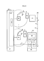
- FIG. 1 shows a communication system KA with a plurality of subscriber line modules SLMC provided for connecting base stations BS, one subscriber line module SLMC being provided for each of the further development variants of the communication system according to the invention shown in FIG.
- the other components of the communication system can be connected to a single subscriber line module SLMC for each configuration variant.
- the subscriber line modules SLMC have ISDN basic lines SO.
- a subscriber line module SLMC is in each case connected to a base station BS of a wireless telephone system via at least one connection V.
- This subscriber line module SLMC which is designed for the connection of base stations BS, differs from subscriber line modules (not shown) for the connection of ISDN communication terminals, in particular with regard to a modified signaling procedure and different data transmission properties.
- the base station BS is equipped for the connection of connections V with ISDN base connections SO implemented in the same way as in the communication system KA - a connection and an ISDN base connection SO is shown as an example.
- the ISDN basic connections SO are additionally equipped with an integrated transmission technology.
- a particularly economical implementation can be achieved by means of a transmission technology in accordance with the time division transmission method.
- Such a transmission connection of base stations to a communication system and an advantageous embodiment of the subscriber line modules SLMC and the base stations BS can advantageously be implemented in accordance with the concept proposed in German patent application 43 09 848.7 for a communication system for connection to a base station of a multi-cellular, wireless telephone system.
- the base station BS is wireless, i.e. via a radio link - at least one KE communication terminal connected.
- the radio connection and the channel structure within the radio connection are implemented in accordance with the DECT standard. This means that twelve communication terminals with bidirectional voice transmission can be connected wirelessly to the base station BS without blocking.
- the signaling information si formed in the communication terminals KE and transmitted by the communication system KA and the bidirectional voice information spi are transmitted via the radio link.
- An ISDN base connection SO of a gateway device GWE is connected to a further subscriber line module SLMC, also equipped with an ISDN base connection, via a first further connection EV1.
- the network gateway device GWE has a connection AL which is connected to a local area network LAN.
- the local area network LAN is implemented by a bus network BN.
- several personal computers PC are connected to the bus line BL in addition to the network gateway device GWE.
- 1 shows an example of the structure of one of the connected personal computers PC1.
- This personal computer PC1 has a network access device NZE, which is connected to the bus line BL of the bus network BN.
- the personal computer PC1 is further equipped with a known input device EE - the known input keyboard or mouse -, a screen device BE and with a microprocessor system CPU, the microprocessor system CPU controlling and monitoring the personal computer PC1.
- this personal computer PC1 is assigned a communication terminal KE connected wirelessly to the base station BS. This means that the signaling for this communication terminal KE can be carried out in the personal computer PC1.
- dialing information is entered, for example, using the comfortable user interface and the user-friendly visualization or read from a telephone book stored in the personal computer PC1 and transmitted to the communication system KA via the bus network BN in the sense of initiating a connection establishment for the assigned communication terminal.
- This Signaling information si can be transmitted in the communication system KA via the subscriber line module SLMC to the base station BS and wirelessly to the communication terminal KE and displayed there.
- the flow of the signaling information si in the communication system KA is explained in more detail in FIG. 2.
- a central control ZST - for example a microcomputer system.
- a further subscriber line module SLMC is connected in FIG. 1 to a transceiver SE of a further wireless transmission system DÜ via a further connection EV2.
- This further connection EV2 is connected to an ISDN base connection SO of the subscriber line module SLMC and the transceiver SE.
- the transceiver SE is wirelessly connected to a wireless gateway device GWE-D.
- the wireless gateway device GWE-D is equipped with a further transceiver SE.
- the wireless gateway GWE-D contains a gateway GWE as described above.
- the gateway device GWE is provided with a connection AL.
- a plurality of personal computers PC to which at least one communication terminal KE connected wirelessly to the base station BS is assigned, cannot be connected to the bus line BL - not shown.
- a gateway device GWE-I integrated into a communication system KA is shown in FIG. 1.
- the structure of this integrated gateway device GWE-I essentially corresponds to the previously described gateway device GWE. Only structural adjustments and adaptations to the physical properties of the communication system have to be made if necessary.
- the integrated gateway device GWE-I also has a connection AL which is connected to a bus line BL of a bus network BN. As previously explained, several personal computers PC can also be connected to these bus lines.
- a further wireless gateway device GWE-BS is connected to a further subscriber line module SLMC, which has an ISDN base connection SO, via a third, further connection EV3 - In particular radio connection - implementing transmitting / receiving device SE is formed.
- the network gateway device GWE is equipped with an ISDN base connection SO.
- wireless network gateway device GWE-BS is connected wirelessly, forming a local, wireless bus network BND, to a number of personal computers PC. 1 shows a personal computer PC2, in which a wireless network access device NZED is arranged.
- the wireless network access device NZED is formed by a previously described network access device NZE and by a transmitter / receiver device SE matched to the transceiver device SE of the wireless gateway device GWE-BS.
- the personal computer PC2 also has a microprocessor system CPU which is connected to a screen device BE, an input device EE and the wireless network access device NZED.
- the personal computer PC2 is also assigned a communication terminal KE that is wirelessly connected to the base station BS.
- the formation and transmission of signaling information si is effected in accordance with the method already explained in personal computer PC1.
- FIG. 2 shows the flow of the signaling information si transmitted from a personal computer PC or a communication terminal KE in a communication system KA, in whose control ST a switching program VP and in its subscriber line modules SLMC a signaling control program SST and a line technology program module LTP in a memory (not shown) is saved.
- a network gateway device GWE and a base station BS are connected to the subscriber line module SLMC, a personal computer PC being connected to the network gateway device GWE and a communication terminal KE assigned to the personal computer PC being connected wirelessly to the base station BS.
- the line technology program module LTP together with the signaling control, handles the connection-specific signaling and information transmission.
- the incentives transmitted by the connections are converted into messages for the switching program VP by means of communication system-specific parameters and transmitted to the latter.
- the switching program VP transmits switching-related messages into connection-specific information, in particular Si gnalization information, implemented.
- the corresponding switching functions for example the connection from subscriber A to subscriber B, are controlled as a function of the transmitted messages, ie signaling information si.
- an assignment routine ZR is inserted in the signaling control.
- signaling information si is transmitted from the personal computer PC to the communication system KA.
- the transmitted signaling information si is also controlled, ie copied, via the line technology program module LTP to the base station BS and to the communication terminal KE and displayed there.
- the prerequisite here is that such an assignment is specified in the assignment routine ZR, for example by an operational input.
- This assignment depends, as explained in FIG. 1, on the assignment of a communication terminal wirelessly connected to a base station BS to a personal computer PC connected to a network access device GWE.
- this assignment is to be changed, for example, by corresponding entries in the communication terminal KE or in a personal computer PC in order to be able to assign a mobile communication terminal to further personal computers PC in different cells of the wireless telephone system.
- signaling information si transmitted from the communication terminal KE is controlled in the communication system KA to the switching program VP and, with the aid of the assignment routine ZR, is simultaneously controlled via the network gateway device GWE to the assigned personal computer PC.
- Signaling information si formed or stored in the communication system KA is controlled with the aid of the assignment routine ZR both to the personal computer PC and to the communication terminal KE.
- the flow of information is shown by dashed or dash-dotted lines.
- FIG. 3 shows in a block diagram a network gateway device GWE, which is connected to the communication system KA via a connection EV1..3 and to the bus network BN via a bus line BL - see FIG. 1.
- the connection EV1..3 is connected to an ISDN base connection SO implemented in a subscriber line module SLMC.
- the signaling information si is read from the signaling channel - denoted D channel in the case of ISDN basic lines - and passed on to a conversion device UE.
- the signals are adapted to the physical controls of an internal interface IS.
- the signaling information si are transmitted to and from the communication system in the signaling channel by signaling packets sp, the information ai indicating a signaling packet being transmitted in the head of a signaling packet sp and the signaling information si in the message part.
- the signaling information si is, in particular, dialing information and information on the control and influencing of performance features.
- the incoming signaling information si is inserted into packets pbn which are suitable for transmission via the bus network BN.
- an origin and a destination address sa are entered in the header of this packet pbn, which are derived from the signaling information si transmitted by the communication system.
- the destination and the origin address sa since represent the network addresses of the personal computers PC connected to the bus network BN.
- the packets pbn formed in this way are controlled via an internal interface IS to an adaptation module MAU and transmitted from there to the bus network BN.
- the adaptation unit MAU is implemented, for example, in accordance with the IEEE standard 802.3.
- signaling signals si are adapted to the physical properties of the bus network BN.
- the signaling information si is read in the packets pbn transmitted by the bus network BN and inserted in signaling packets sp.
- the repacking of the signaling information si and the formation of the destination and the source addresses sa, is effected with the aid of a signaling routine SR stored in the conversion device UE, by means of which an assigned microprocessor system CPU of the conversion device UE is controlled.
- the microprocessor system CPU connected to the ISDN base connection SO and the adaptation module MAU monitors and coordinates the functions of the conversion device UE.
- 4 shows a communication system KA with a central control ST and a subscriber line module SLMC to the base stations BS of a wireless, multi-cellular telephone system can be connected.
- 4 shows two base stations BS as an example, wherein a plurality of communication terminals KE can each be connected wirelessly to the base stations BS.
- the circles around the base stations BS represent the associated radio area.
- the base stations BS are connected to the communication system KA either by an ISDN base connection SO or by an ISDN base connection equipped with integrated transmission technology, in particular in accordance with the time separation transmission method.
- the subscriber line module SLMC is connected to a personal computer PC via a further ISDN basic line SO.
- personal computer PC is equipped with an ISDN basic connection module SOM.
- this ISDN base connection module SOM is connected to a known input, screen and microprocessor device EE, BE, CPU and, moreover, to an adaptation unit MAU, which is constructed in the same way as the adaptation unit MAU explained in FIG.
- the functions of a conversion device UE according to FIG. 3 are implemented in the microprocessor device CPU in terms of program technology by a conversion routine UER.
- the adaptation unit MAU, the ISDN basic connection module SOM and the conversion routine UER together represent a gateway GWE integrated in one of the personal computers PC of the bus network BN.
- the adaptation unit MAU is connected to a bus line BL of a bus network BN, to which several personal computers PC can be connected, a further personal computer PC being shown as an example in FIG.
- Each of the personal computers PC is assigned one of the communication terminals KE connected wirelessly to one of the base stations BS.
- the switching-related assignment of the communication terminals KE to the personal computers PC is effected by an assignment routine ZR implemented in the subscriber line module SLMC.
- the flow of the signaling information si from and to the communication system KA - see FIG. 2 - is controlled by this.
- This embodiment variant of the communication system according to the invention is advantageously used in multi-cellular, i.e. larger wireless telephone network.
Abstract
Description
Die Erfindung betrifft ein Kommunikationssystem mit durch ein lokales Netz verbundenen Personalcomputern, denen jeweils zumindest ein Kommunikationsendgerät eines drahtlosen, zumindest eine Basisstation umfassenden Fernsprechsystems zugeordnet ist, wobei die zumindest eine Basisstation mit einer Kommunikationsanlage über eine Verbindung verbunden ist.The invention relates to a communication system with personal computers connected by a local network, each of which is assigned at least one communication terminal of a wireless telephone system comprising at least one base station, the at least one base station being connected to a communication system via a connection.
Drahtlose Fernsprechsysteme umfassen eine Basisstation - bzw. ein Festteil -, an die über eine Funkverbindung ein oder mehrere Kommunikationsendgeräte - bzw. Mobilteile - angeschlossen sind. Die Funkübertragung erfolgt beispielsweise gemäß dem DECT - Standard (Digital European Cordless Telephony) oder dem GSM - Standard (Group Special Mobile). In diesen Standards sind neben den funktechnischen Festlegungen die Kanalstrukturen für einen drahtlosen Anschluß mehrerer Kommunikationsendgeräte definiert. Die Basisstationen sind mit Hilfe bekannter Übertragungstechniken - z.B. analoge oder digitale Übertragungsverfahren - über ein oder mehrere Verbindungen mit einer Kommunikationsanlage - insbesondere einer Fernsprechnebenstellenanlage - verbunden. Hierzu ist die Kommunikationsanlage mit analogen a/b - Schnittstellen oder mit digitalen ISDN - Schnittstellen ausgestattet.Wireless telephone systems comprise a base station - or a fixed part - to which one or more communication terminals - or mobile parts - are connected via a radio link. The radio transmission takes place, for example, according to the DECT standard (Digital European Cordless Telephony) or the GSM standard (Group Special Mobile). In addition to the radio-technical stipulations, these standards define the channel structures for a wireless connection of several communication terminals. The base stations are using known transmission techniques - e.g. Analog or digital transmission methods - connected via one or more connections to a communication system - in particular a private branch exchange. For this purpose, the communication system is equipped with analog a / b interfaces or with digital ISDN interfaces.
Bei einer Zuordnung eines Kommunikationsendgerätes eines drahtlosen Fernsprechsystems zu einem Personalcomputer, bei dem das Kommunikationsendgerät im Sinne eines schnurlosen Hörers für einen Personalcomputer wirkt - PC-Telefon -, sind in diesem zusätzliche Programme und eine Fernsprechkarte installiert, an die sowohl die Kommunikationsanlage als auch die Basisstation angeschlossen sind. Bei dieser Zuordnung wird der Anschluß einer Basisstation, d.h. Nachrichten- und Signalisierungskanäle, durch den Personalcomputer geführt, wodurch die Signalisierung vorn Kommunikationsendgerät zur Kommunikationsanlage und umgekehrt im Personalcomputer mitgelesen, an dessen Bildschirm visualisiert und beeinflußt werden kann. Darüberhinaus kann die Signalisierung für das zugeordnete Kommunikationsendgerät vollständig durch den Personalcomputer abgewikkelt werden. Dies bedeutet, daß die Signalisierungsinformationen - z.B. Wahlinformationen - im Personalcomputer bedieneroberflächengesteuert - z.B. mit Hilfe der Eingabetastatur oder einer Maus - gebildet und an die Kommunikationsanlage übermittelt werden. Aufgrund der komfortablen Bedieneroberfläche und Visualisierung am Bildschirm des Personalcomputers wird eine komfortable Signalisierung für die zugeordneten Kommunikationsendgeräte erreicht und zusätzlich sind unterschiedliche, die Signalisierung unterstützende Funktionen - z.B. ein Telefonverzeichnis mit Suchprozeduren - komfortabel realisierbar.When assigning a communication terminal of a wireless telephone system to a personal computer, in which the communication terminal acts as a cordless handset for a personal computer - PC telephone - additional programs and a telephone card are installed in it, to which both the communication system and the base station are installed are connected. With this assignment, the connection of a base station, i.e. Message and signaling channels, guided by the personal computer, whereby the signaling is read from the communication terminal to the communication system and vice versa in the personal computer, which can be visualized and influenced on its screen. In addition, the signaling for the associated communication terminal can be handled entirely by the personal computer. This means that the signaling information - e.g. Dialing information - user interface controlled in the personal computer - e.g. using the input keyboard or a mouse - are formed and transmitted to the communication system. Due to the convenient user interface and visualization on the screen of the personal computer, convenient signaling is achieved for the assigned communication terminals and, in addition, different functions that support the signaling - e.g. a telephone directory with search procedures - easy to implement.
Eine derartige Kommunikationsanordnung eines Personalcomputers mit einem zugeordneten drahtlosen Fernsprechsystem erfordert einen erheblichen programmtechnischen und schaltungstechnischen Aufwand im Personalcomputer - zusätzliche Fernsprechkarte einschließlich der Programme.Such a communication arrangement of a personal computer with an associated wireless telephone system requires a considerable amount of programming and circuitry in the personal computer - additional telephone card including the programs.
Desweiteren sind Personalcomputer insbesondere in größeren Verwaltungseinheiten mit Hilfe eines lokalen Netzes vernetzt. Für die Vernetzung von Personalcomputern werden insbesondere lokale Busnetze eingesetzt, die in der Fachwelt auch als Ethernet oder Cheapernet bekannt sind. Der Zugriff der einzelnen Personalcomputer auf das Busnetz bzw. die Busleitung erfolgt überwiegend gemäß dem im IEEE-Standard 802.3 standardisierten CSMA/CD-Verfahren (Carrier Sense Multiple Access with Collision Detection). In zunehmendem Maße, insbesondere aufgrund geforderter hoher Datenübermittlungsraten sind auch Ring- oder Sternnetze, beispielsweise gemäß dem IEEE-Standard 802.4 bis 802.6 vorgesehen.Furthermore, personal computers are networked in particular in larger administrative units with the help of a local network. Local bus networks, which are also known in the technical field as Ethernet or cheapernet, are used in particular for networking personal computers. The access of the individual personal computers to the bus network or the bus line takes place predominantly in accordance with the CSMA / CD procedure (Carrier Sense Multiple Access with Collision Detection) standardized in the IEEE standard 802.3. To an increasing extent, in particular due to the required high data transmission rates, ring or star networks are also provided, for example in accordance with the IEEE standard 802.4 to 802.6.
Die der Erfindung zugrundeliegende Aufgabe besteht darin, den Aufwand für eine Zuordnung eines Kommunikationsendgerätes eines drahtlosen Fernsprechsystems zu einem Personalcomputer zu vermindern. Die Aufgabe wird ausgehend von einem Kommunikationssystem gemäß den Merkmalen des Oberbegriffs des Patentanspruchs 1 durch dessen kennzeichnende Merkmale gelöst.The object on which the invention is based is to reduce the effort for assigning a communication terminal of a wireless telephone system to a personal computer. The object is achieved on the basis of a communication system in accordance with the features of the preamble of
Der wesentliche Aspekt der Erfindung ist darin zu sehen, daß im lokalen Netz eine Netzübergangseinrichtung angeordnet ist, die über zumindest eine weitere Verbindung mit der Kommunikationsanlage verbunden ist, und die Kommunikationsanlage und die Netzübergangseinrichtung sind derart ausgestaltet, daß im jeweiligen Personalcomputer oder im jeweils zugordneten Kommunikationsendgerät gebildete oder gespeicherte Signalisierungsinformationen an die Kommunikationsanlage und in der Kommunikationsanlage gebildete oder gespeicherte Signalisierungsinformationen sowohl an den jeweiligen Personalcomputer als auch an das jeweils zugeordnete Kommunikationsendgerät gesteuert werden. Zusätzlich kann das Kommunikationssystem und die Netzübergangseinrichtung derart ausgestaltet sein, daß im Personalcomputer bzw. im Kommunikationsendgerät gebildete Signalisierungsinformationen zusätzlich an das zugeordnete Kommunikationsendgerät bzw. den zugeordneten Personalcomputer gesteuert werden - Anspruch 2.The essential aspect of the invention can be seen in the fact that a network gateway device is arranged in the local network, which is connected to the communication system via at least one further connection, and the communication system and the network gateway device are designed such that in the respective personal computer or in the respectively assigned communication terminal formed or stored signaling information to the communication system and signaling information formed or stored in the communication system can be controlled both on the respective personal computer and on the respectively assigned communication terminal. In addition, the communication system and the gateway device can be designed such that signaling information formed in the personal computer or in the communication terminal is additionally controlled to the assigned communication terminal or the assigned personal computer.
Das erfindungsgemäße Kommunikationssystem mit einer an die Kommunikationsanlage angeschlossenen Netzübergangseinrichtung wird vorteilhaft für mehrere an ein lokales Netz angeschlos-sene Personalcomputer eingesetzt, denen jeweils ein Kommunikationsendgerät eines drahtlosen Fernsprechsystems zugeordnet ist, da der Aufwand für eine Realisierung einer Netzübergangseinrichtung gegenüber dem Aufwand für mehrere zusätzliche Fernsprechkarten erheblich geringer ist. Besonders vorteilhaft ist das erfindungsgemäße Kommunikationssystem bei einem bereits vorhandenen Anschluß eines mit mehreren Personalcomputern verbundenen lokalen Netzes an eine Kommunikationsanlage zu realisieren, da hierbei lediglich in der Kommunikationsanlage die vermittlungstechnische Zuordnung des jeweilichen Personalcomputers zu dem zugeordneten Kommunikationsendgerät insbesondere programmtechnisch zu realisieren ist. Gegenüber einer Lösung mit Fernsprechkarten in den Personalcomputern ist ein weiterer Vorteil des erfindungsgemäßen Kommunikationssystems darin zu sehen, daß bei einem Ausfall des Personalcomputers die Funktionsfähigkeit der Basisstationen uneingeschränkt erhalten bleibt.The communication system according to the invention with a network gateway device connected to the communication system is advantageously used for several personal computers connected to a local network, each of which has a communication terminal of a wireless telephone systems is assigned, since the effort for implementing a gateway device is considerably less than the effort for several additional telephone cards. It is particularly advantageous to implement the communication system according to the invention with an already existing connection of a local network connected to several personal computers to a communication system, since in this case only the communication system can be used to assign the respective personal computer to the assigned communication terminal, particularly in terms of programming. Compared to a solution with telephone cards in the personal computers, a further advantage of the communication system according to the invention can be seen in the fact that the functionality of the base stations is retained without restriction in the event of a failure of the personal computer.
Vorteilhaft ist die Verbindung zwischen der zumindest einen Basisstation und der Kommunikationsanlage und die weitere Verbindung zwischen der Netzübergangseinrichtung und der Kommunikationsanlage durch zumindest eine Leitung realisiert und die Leitung ist jeweils mit einem Anschluß der Kommunikationsanlage und mit einem Anschluß der Basisstation oder Netzübergangseinrichtung verbunden - Anspruch 3. Alternativ ist die Verbindung zwischen der Netzübergangseinrichtung und der Kommunikationsanlage durch eine drahtlose Verbindung realisiert und die drahtlose Verbindung ist jeweils mit einem Anschluß der Kommunikationsanlage und mit einem Anschluß der Netzübergangseinrichtung verbunden - Anspruch 4.The connection between the at least one base station and the communication system and the further connection between the gateway device and the communication system is advantageously realized by at least one line and the line is connected to a connection of the communication system and to a connection of the base station or gateway device - claim 3. Alternatively, the connection between the gateway device and the communication system is realized by a wireless connection, and the wireless connection is in each case connected to a connection of the communication system and to a connection of the gateway device.
Die Anschlüsse der Kommunikationsanlage und die Anschlüsse der zumindest einen Basisstation und der Netzübergangseinrichtung sind vorteilhaft durch einen ISDN-orientierten Anschluß realisiert - Anspruch 5. Hierbei sind die eine oder mehreren Basisstationen an die Kommunikationsanlage vorzugsweise jeweils an einen ISDN-Basisanschluß SO angeschlossen. Beispielsweise ist eine gemäß dem DECT-Standard realisierte Basisstation - d.h. an eine Basisstation sind zwölf Kommunikationsendgeräte blockierungsfrei anschließbar - über drei SO - Basisanschlüsse angeschlossen, wobei über einen Basisanschluß mit zwei 64 kbit/s - Nachrichtenkanälen vier komprimierte - 32 kbit/s drahtlose Kommunikationsendgeräte bidirektional vermittelt werden. Der Anschluß der Netzübergangseinrichtung ist in Abhängigkeit von der Anzahl der an das lokale Netz angeschlossenen Personalcomputer mit einem zugeordneten Kommunikationsendgerät eines drahtlosen Fernsprechsystems durch einen ISDN-Basisanschluß oder durch einen ISDN-Multiplexanschluß realisierbar, wobei ein ISDN-Basisanschluß zwei und ein ISDN-Multiplexanschluß dreißig Nachrichtenkanäle aufweist. Alternativ sind die ISDN- Basisanschlüsse zusätzlich mit einer integrierten Übertragungstechnik ausgestattet. Eine besonders wirtschaftliche Realisierung ist durch eine Übertragungstechnik gemäß dem Zeitgetrenntlage- Übertragungsverfahren erreichbar. Eine derartige übertragungstechnische Anbindung von Basisstationen an eine Kommunikationsanlage ist vorteilhaft gemäß dem in der deutschen Patentanmeldung 41 41 493.4 vorgeschlagenen Übertragungskonzept realisierbar.The connections of the communication system and the connections of the at least one base station and the gateway device are advantageously realized by an ISDN-oriented connection. Here, the one or more base stations are preferably connected to the communication system each to an ISDN base connection SO. For example, a base station implemented according to the DECT standard - i.e. Twelve communication terminals can be connected to a base station without blocking - connected via three SO base connections, four compressed - 32 kbit / s wireless communication terminals being transmitted bidirectionally via a base connection with two 64 kbit / s message channels. Depending on the number of personal computers connected to the local network with an assigned communication terminal of a wireless telephone system, the connection of the gateway device can be implemented through an ISDN basic connection or through an ISDN multiplex connection, one ISDN basic connection two and one ISDN multiplex connection thirty message channels having. Alternatively, the ISDN basic connections are additionally equipped with an integrated transmission technology. A particularly economical implementation can be achieved using a transmission technology in accordance with the time separation transmission method. Such a transmission connection of base stations to a communication system can advantageously be implemented in accordance with the transmission concept proposed in German patent application 41 41 493.4.
Gemäß einer Weiterbildung des erfindungsgemäßen Kommunikationssystem ist das lokale Netz (LAN) durch ein lokales Busnetz realisiert und die Personalcomputer werden mit Hilfe von Netzzugriffseinrichtungen an das lokale Busnetz gekoppelt - Anspruch 7. Vorteilhaft ist das lokale Busnetz gemäß dem IEEE-Standard 802.3 realisiert - Anspruch 8. Ein Busnetz gemäß dem IEEE-Standard 802.3 ist besonders wirtschaftlich realisierbar, da für die häufig eingesetzen Busnetze kostengünstige Netzkomponenten verfügbar sind.According to a development of the communication system according to the invention, the local area network (LAN) is implemented by a local bus network and the personal computers are coupled to the local bus network with the aid of network access devices.
Alternativ ist das lokale Netz durch ein drahtloses, lokales Busnetz realisierbar - Anspruch 9. Zubeachten ist hierbei, daß die Sende- und Empfangsfrequenzen des drahtlosen Fernsprechsystems und des drahtlosen Busnetzes derart bestimmt sind, daß eine gegenseitige Beeinflussung vermieden wird. Sowohl bei einem drahtgebundenem als auch bei einem drahtlosen Busnetz ist die Netzübergangseinrichtung in die Kommunikationsanlage integrierbar - Anspruch 6. Durch die Integration können physikalische Schnittstellenanpassungen vermieden und insbesondere konstruktive Einsparungen erreicht werden.Alternatively, the local network can be implemented by a wireless, local bus network - claim 9. It should be noted here that the transmission and reception frequencies of the wireless telephone system and the wireless bus network are determined in such a way that mutual interference is avoided. The gateway device can be integrated into the communication system both in the case of a wired and a wireless bus network - claim 6. The integration enables physical interface adaptations to be avoided and, in particular, constructive savings to be achieved.
Für die vermittlungstechnische Zuordnung ist in der Kommunikationsanlage eine Zuordnungsroutine derart ausgestaltet, daß die in der Kommunikationsanlage gebildeten oder gespeicherten Signalisierungsinformationen über die betreffenden Teilnehmeranschlüsse an die betroffene Basisstation und an die betroffene Netzübergangseinrichtung übermittelt werden - Anspruch 10. Die Zuordnungsroutine stellt einen programmtechnischen Teil des Vermittlungsprogramms der Kommunikationsanlage dar und ist in dieses in Abhängigkeit von der Ausgestaltung des vorhandenen Vermittungsprogramms eingebunden oder in diesem als eigenständige Routine implementiert.For the switching-related assignment, an assignment routine is designed in the communication system in such a way that the signaling information formed or stored in the communication system is transmitted via the subscriber connections concerned to the base station concerned and to the network gateway device concerned - claim 10. The assignment routine represents a program-related part of the switching program of Communication system and is integrated in this depending on the design of the existing switching program or implemented in this as an independent routine.
Zur vermittlungstechnischen Steuerung der Netzübergangseinrichtung ist in dieser eine Signalisierungsroutine derart ausgestaltet, daß die kommunikationsanlagengemäßen Signalisierungsinformationen und die Netzadressen der betroffenen Personalcomputer in lokale-Netz-gemäße Übertragungstelegramme eingefügt werden - Anspruch 11. Die Netzadressen der Personalcomputer im lokalen Netz werden mit Hilfe der Zuordnungsroutine der Kommunikationsanlage oder der Signalisierungsroutine der Netzübergangseinrichtung ermittelt - Anspruch 12.For switching control of the gateway device, a signaling routine is designed in such a way that the signaling information in accordance with the communication system and the network addresses of the personal computers concerned are inserted into local network-conforming transmission telegrams - claim 11 Communication system or the signaling routine of the gateway device determined - claim 12.
Im folgenden ist das erfindungsgemäße Kommunikationssystem anhand dreier Blockschaltbilder näher erläutert. Dabei zeigen
- Fig. 1 in einem Blockschaltbild mehrere Ausgestaltungsvarianten des erfingungsgemäßen Kommunikationssystems,
- Fig. 2 in einem Blockschaltbild die Programmstruktur der Kommunikationsanlage mit einer Zuordnungsroutine,
- Fig. 3 in einem Blockschaltbild den Aufbau einer Netzübergangseinrichtung mit einer Signalisierungsroutine und
- Fig. 4 in einem Blockschaltbild das erfindungsgemäße Kommunikationssystem mit mehreren Basisstationen und mehreren Personalcomputern.
- 1 shows a block diagram of several design variants of the communication system according to the invention,
- 2 is a block diagram of the program structure of the communication system with an assignment routine,
- Fig. 3 in a block diagram the structure of a gateway with a signaling routine and
- Fig. 4 in a block diagram the communication system according to the invention with several base stations and several personal computers.
Fig. 1 zeigt eine Kommunikationsanlage KA mit mehreren für den Anschluß von Basistationen BS vorgesehenen Teilnehmeranschlußmodulen SLMC, wobei für die in Fig. 1 dargestellten Weiterbildungsvarianten des erfindungsgemäßen Kommunikationssystems jeweils ein Teilnehmeranschlußmodul SLMC vorgesehen ist. Prinzipiell sind die weiteren Komponenten des Kommunikationssystems für jede Ausgestaltungsvariante an ein einziges Teilnehmeranschlußmodul SLMC anschließbar. Für das Ausführungsbeispiel sei angenommen, daß die Teilnehmeranschlußmodule SLMC ISDN-Basisanschlüsse SO aufweisen. Ein Teilnehmeranschlußmodul SLMC ist jeweils über zumindest eine Verbindung V mit einer Basisstation BS eines drahtlosen Fernsprechsystems verbunden. Dieses für den Anschluß von Basistationen BS ausgestaltete Teilnehmeranschlußmodul SLMC unterscheidet sich von nicht dargestellten Teilnehmeranschlußmodulen für den Anschluß von ISDN - Kommunikationsendgeräten insbesondere hinsichtlich einer modifizierten Signalisierungsprozedur und unterschiedlichen Datenübertragungseigenschaften. Die Basisstation BS ist für den Anschluß von Verbindungen V mit gleichartig wie in der Kommunikationsanlage KA realisierten ISDN-Basisanschlüssen SO ausgestattet - beispielhaft ist eine Verbindung und ein ISDN- Basisanschluß SO dargestellt. Alternativ - nicht dargestellt - sind die ISDN- Basisanschlüsse SO zusätzlich mit einer integrierten Übertragungstechnik ausgestattet. Eine besonders wirtschaftliche Realisierung ist durch eine Übertragungstechnik gemäß dem Zeitgetrenntlage-Übertragungsverfahrenerreichbar. Eine derartige übertragungstechnische Anbindung von Basisstationen an eine Kommunikationsanlage sowie eine vorteilhafte Ausgestaltung der Teilnehmeranschlußmodule SLMC und der Basisstationen BS ist vorteilhaft gemäß des in der deutschen Patentanmeldung 43 09 848.7 vorgeschlagenen Konzeptes für ein Kommunikationssystem zum Anschluß an eine Basisstation eines mehrzellularen, drahtlosen Fernsprechsystems realisierbar.1 shows a communication system KA with a plurality of subscriber line modules SLMC provided for connecting base stations BS, one subscriber line module SLMC being provided for each of the further development variants of the communication system according to the invention shown in FIG. In principle, the other components of the communication system can be connected to a single subscriber line module SLMC for each configuration variant. For the exemplary embodiment it is assumed that the subscriber line modules SLMC have ISDN basic lines SO. A subscriber line module SLMC is in each case connected to a base station BS of a wireless telephone system via at least one connection V. This subscriber line module SLMC, which is designed for the connection of base stations BS, differs from subscriber line modules (not shown) for the connection of ISDN communication terminals, in particular with regard to a modified signaling procedure and different data transmission properties. The base station BS is equipped for the connection of connections V with ISDN base connections SO implemented in the same way as in the communication system KA - a connection and an ISDN base connection SO is shown as an example. Alternatively - not shown - the ISDN basic connections SO are additionally equipped with an integrated transmission technology. A particularly economical implementation can be achieved by means of a transmission technology in accordance with the time division transmission method. Such a transmission connection of base stations to a communication system and an advantageous embodiment of the subscriber line modules SLMC and the base stations BS can advantageously be implemented in accordance with the concept proposed in German patent application 43 09 848.7 for a communication system for connection to a base station of a multi-cellular, wireless telephone system.
An die Basisstation BS ist drahtlos, d.h. über eine Funkverbindung - mindestens ein Kommunikationsendgerät KE angeschlossen. Für das Ausführungsbeispiel sei angenommen, daß die Funkverbindung und die Kanalstruktur innerhalb der Funkverbindung gemäß dem DECT-Standard realisiert sind. Dies bedeutet, daß an die Basisstation BS drahtlos zwölf Kommunikationsendgeräte mit bidirektionaler Sprachübertragung blockierungsfrei anschließbar sind. Über die Funkverbindung werden die in den Kommunikationsendgeräten KE gebildeten und die von der Kommunikationsanlage KA übermittelten Signalisierungsinformationen si sowie die bidirektional zu übermittelnden Sprachinformationen spi übertragen.To the base station BS is wireless, i.e. via a radio link - at least one KE communication terminal connected. For the exemplary embodiment it is assumed that the radio connection and the channel structure within the radio connection are implemented in accordance with the DECT standard. This means that twelve communication terminals with bidirectional voice transmission can be connected wirelessly to the base station BS without blocking. The signaling information si formed in the communication terminals KE and transmitted by the communication system KA and the bidirectional voice information spi are transmitted via the radio link.
An ein weiteres, ebenfalls mit einem ISDN-Basisanschluß ausgestattetes Teilnehmeranschlußmodul SLMC ist über eine erste weitere Verbindung EV1 ein ISDN-Basisanschluß SO einer Netzübergangseinrichtung GWE angeschlossen. Die Netzübergangseinrichtung GWE weist einen Anschluß AL auf, der mit einem lokalen Netz LAN verbunden ist. Für das Ausführungsbeispiel sei angenommen, daß das lokale Netz LAN durch ein Busnetz BN realisiert ist. Hierbei sind an die Busleitung BL neben der Netzübergangseinrichtung GWE mehrere Personalcomputer PC angeschlossen. In Fig. 1 ist beispielhaft der Aufbau eines der angeschlossenen Personalcomputer PC1 dargestellt. Dieser Personalcomputer PC1 weist eine Netzzugriffseinrichtung NZE auf, die mit der Busleitung BL des Busnetzes BN verbunden ist. Der Personalcomputer PC1 ist weiterhin mit einer bekannten Eingabeeinrichtung EE - die bekannte Eingabetastatur oder Maus -, einer Bildschirmeinrichtung BE und mit einem Mikroprozessorsystem CPU ausgestattet, wobei das Mikroprozessorsystem CPU den Personalcomputer PC1 steuert und überwacht. Für das Ausführungsbeispiel sei weiterhin angenommen, daß diesem Personalcomputer PC1 ein drahtlos an die Basisstation BS angeschlossenes Kommunikationsendgerät KE zugeordnet ist. Dies bedeutet, daß die Signalisierung für dieses Kommunikationsendgerät KE im Personalcomputer PC1 durchgeführt werden kann. Hierzu werden beispielsweise mit Hilfe der komfortablen Bedieneroberfläche und der bedienerfreundlichen Visualisierung Wählinformationen eingegeben oder aus einem im Personalcomputer PC1 gespeicherten Telefonbuch ausgelesen und im Sinne eines Einleitens eines Verbindungsaufbaus für das zugeordnete Kommunikationsendgerät über das Busnetz BN, die Netzübergangseinrichtung GWE an die Kommunikationsanlage KA übermittelt. Diese Signalisierungsinformationen si können in der Kommunikationsanlage KA über das Teilnehmeranschlußmodul SLMC an die Basisstation BS und drahtlos an das Kommunikationsendgerät KE übermittelt und dort angezeigt werden. Der Fluß der Signalisierungsinformation si in der Kommunikationsanlage KA ist in Fig. 2 näher erläutert. Für die Steuerung - auch der Signalisierungsinformationen si - und Überwachung der Kommunikationsanlage KA ist diese mit einer zentralen Steuerung ZST - z.B. ein Microcomputersystem - ausgestattet.An ISDN base connection SO of a gateway device GWE is connected to a further subscriber line module SLMC, also equipped with an ISDN base connection, via a first further connection EV1. The network gateway device GWE has a connection AL which is connected to a local area network LAN. For the exemplary embodiment it is assumed that the local area network LAN is implemented by a bus network BN. In this case, several personal computers PC are connected to the bus line BL in addition to the network gateway device GWE. 1 shows an example of the structure of one of the connected personal computers PC1. This personal computer PC1 has a network access device NZE, which is connected to the bus line BL of the bus network BN. The personal computer PC1 is further equipped with a known input device EE - the known input keyboard or mouse -, a screen device BE and with a microprocessor system CPU, the microprocessor system CPU controlling and monitoring the personal computer PC1. For the exemplary embodiment it is further assumed that this personal computer PC1 is assigned a communication terminal KE connected wirelessly to the base station BS. This means that the signaling for this communication terminal KE can be carried out in the personal computer PC1. For this purpose, dialing information is entered, for example, using the comfortable user interface and the user-friendly visualization or read from a telephone book stored in the personal computer PC1 and transmitted to the communication system KA via the bus network BN in the sense of initiating a connection establishment for the assigned communication terminal. This Signaling information si can be transmitted in the communication system KA via the subscriber line module SLMC to the base station BS and wirelessly to the communication terminal KE and displayed there. The flow of the signaling information si in the communication system KA is explained in more detail in FIG. 2. For the control - also of the signaling information si - and monitoring of the communication system KA, this is equipped with a central control ZST - for example a microcomputer system.
Gemäß einer weiteren vorteilhaften Ausgestaltung des erfindungsgemäßen Kommunikationssystems ist in Fig. 1 ein weiteres Teilnehmeranschlußmodul SLMC mit einer Sende-/Empfangseinrichtung SE eines weiteren drahtlosen Übertragungssystems DÜ über eine weitere Verbindung EV2 verbunden. Diese weitere Verbindung EV2 ist jeweils an einen ISDN-Basisanschluß SO des Teilnehmeranschlußmoduls SLMC und der Sende- /Empfangseinrichtung SE angeschlossen. Die Sende-/Empfangseinrichtung SE ist drahtlos mit einer drahtlosen Netzübergangseinrichtung GWE-D verbunden. Hierzu ist die drahtlose Netzübergangseinrichtung GWE-D mit einer weiteren Sende-/Empfangseinrichtung SE ausgestattet. Desweiteren ist in der drahtlosen Netzübergangseinrichtung GWE-D eine wie vorhergehend beschriebene Netzübergangseinrichtung GWE enthalten. Für den Anschluß einer Busleitung BL eines Busnetzes BN ist die Netzübergangseinrichtung GWE mit einem Anschluß AL versehen. An die Busleitung BL sind - wie vorhergehend erläutert - mehrere Personalcomputer PC anschließbar, denen jeweils zumindest ein drahtlos an die Basisstation BS angeschlossenes Kommunikationsendgerät KE zugeordnet ist - nicht dargestellt.According to a further advantageous embodiment of the communication system according to the invention, a further subscriber line module SLMC is connected in FIG. 1 to a transceiver SE of a further wireless transmission system DÜ via a further connection EV2. This further connection EV2 is connected to an ISDN base connection SO of the subscriber line module SLMC and the transceiver SE. The transceiver SE is wirelessly connected to a wireless gateway device GWE-D. For this purpose, the wireless gateway device GWE-D is equipped with a further transceiver SE. Furthermore, the wireless gateway GWE-D contains a gateway GWE as described above. For the connection of a bus line BL of a bus network BN, the gateway device GWE is provided with a connection AL. As previously explained, a plurality of personal computers PC, to which at least one communication terminal KE connected wirelessly to the base station BS is assigned, cannot be connected to the bus line BL - not shown.
Gemäß einer weiteren Ausgestaltung des erfindungsgemäßen Kommunikationssystems ist in Fig. 1 eine in eine Kommunikationsanlage KA integrierte Netzübergangseinrichtung GWE-I dargestellt. Der Aufbau dieser integrierten Netzübergangseinrichtung GWE-I entspricht im wesentlichen der vorhergehend erläuterten Netzübergangseinrichtung GWE. Lediglich konstruktive Anpassungen und Anpassungen an die kommunikationsanlageninternen physikalischen Eigenschaften sind gegebenenfalls vorzunehmen. Die integrierte Netzübergangseinrichtung GWE-I weist ebenfalls einen Anschluß AL auf, der mit einer Busleitung BL eines Busnetzes BN verbunden ist. An diese Busleitungen sind - wie vorhergehend erläutert - ebenfalls mehrere Personalcomputer PC anschließbar.According to a further embodiment of the communication system according to the invention, a gateway device GWE-I integrated into a communication system KA is shown in FIG. 1. The structure of this integrated gateway device GWE-I essentially corresponds to the previously described gateway device GWE. Only structural adjustments and adaptations to the physical properties of the communication system have to be made if necessary. The integrated gateway device GWE-I also has a connection AL which is connected to a bus line BL of a bus network BN. As previously explained, several personal computers PC can also be connected to these bus lines.
Gemäß einer weiteren Ausgestaltungsvariante des erfindungsgemäßen Kommunikationssystems ist an ein weiteres, einen ISDN-Basisanschluß SO aufweisendes Teilnehmeranschlußmodul SLMC über eine dritte, weitere Verbindung EV3 eine weitere drahtlose Netzübergangseinrichtung GWE-BS angeschlossen, die durch eine vorhergehend erläuterte Netzübergangseinrichtung GWE sowie eine, eine weitere drahtlose Verbindung - insbesondere Funkverbindung - realisierende Sende-/Empfangseinrichtung SE gebildet ist. Für den Anschluß der dritten, weiteren Verbindung EV3 ist die Netzübergangseinrichtung GWE mit einem ISDN-Basisanschluß SO ausgestattet. Diese weitere, drahtlose Netzübergangseinrichtung GWE-BS ist drahtlos, ein lokales, drahtloses Busnetz BND bildend, mit mehreren Personalcomputern PC verbunden. Beispielhaft ist in Fig. 1 ein Personalcomputer PC2 dargestellt, in dem eine drahtlose Netzzugriffseinrichtung NZED angeordnet ist. Die drahtlose Netzzugriffseinrichtung NZED ist durch eine vorhergehend beschriebenen Netzzugriffseinrichtung NZE und durch eine auf die Sende-/Empfangseinrichtung SE der drahtlosen Netzübergangseinrichtung GWE-BS abgestimmte Sende-/Empfangseinrichtung SE gebildet. Der Personalcomputer PC2 weist des weiteren ein Mikroprozessorsystem CPU auf, das mit einer Bildschirmeinrichtung BE, einer Eingabeeinrichtung EE und der drahtlosen Netzzugriffseinrichtung NZED verbunden ist. Dem Personalcomputer PC2 ist des weiteren ein mit der Basisstation BS drahtlos verbundenes Kommunikationsendgerät KE zugeordnet. Das Bilden und Übermitteln von Signalisierungsinformationen si wird entsprechend dem bereits erläuterten Verfahren in Personalcomputer PC1 bewirkt.According to a further embodiment variant of the communication system according to the invention, a further wireless gateway device GWE-BS is connected to a further subscriber line module SLMC, which has an ISDN base connection SO, via a third, further connection EV3 - In particular radio connection - implementing transmitting / receiving device SE is formed. For the connection of the third, further connection EV3, the network gateway device GWE is equipped with an ISDN base connection SO. This further, wireless network gateway device GWE-BS is connected wirelessly, forming a local, wireless bus network BND, to a number of personal computers PC. 1 shows a personal computer PC2, in which a wireless network access device NZED is arranged. The wireless network access device NZED is formed by a previously described network access device NZE and by a transmitter / receiver device SE matched to the transceiver device SE of the wireless gateway device GWE-BS. The personal computer PC2 also has a microprocessor system CPU which is connected to a screen device BE, an input device EE and the wireless network access device NZED. The personal computer PC2 is also assigned a communication terminal KE that is wirelessly connected to the base station BS. The formation and transmission of signaling information si is effected in accordance with the method already explained in personal computer PC1.
Fig. 2 zeigt den Fluß der von einem Personalcomputer PC oder einen Kommunikationsendgerät KE übermittelten Signalisierungsinformationen si in einer Kommunikationsanlage KA, in deren Steuerung ST ein Vermittlungsprogramm VP und in deren Teilnehmeranschlußmodulen SLMC ein Signalisierungssteuerungsprogramm SST sowie ein Leitungstechnik-Programmodul LTP in jeweils einem nicht dargestellten Speicher gespeichert ist. Beispielhaft sind an des Teilnehmeranschlußmodul SLMC eine Netzübergangseinrichtung GWE und eine Basisstation BS angeschlossen, wobei an die Netzübergangseinrichtung GWE beispielhaft ein Personalcomputer PC und an die Basisstation BS drahtlos ein dem Personalcomputer PC zugeordnetes Kommunikationsendgerät KE angeschlossen ist. Das Leitungstechnik-Programmodul LTP wickelt zusammen mit der Signalisierungssteuerung die anschlußartenindividuellen Signalisierungen und Informationsübertragungen ab. Hierbei werden die von den Anschlüssen übermittelten Anreize mittels kommunikationsanlagenspezifischer Parameter in Meldungen für das Vermittlungsprogramm VP umgesetzt und an dieses übermittelt. Analog hierzu werden vom Vermittlungsprogramm VP übermittelten vermittlungstechnischen Meldungen in anschlußindividuelle Informationen, insbesondere Signalisierungsinformationen, umgesetzt. Im Vermittlungsprogramm VP werden in Abhängigkeit der übermittelten Meldungen, d.h. Signalisierungsinformationen si die entsprechenden vermittlungstechnischen Funktionen, z.B. Verbindung von Teilnehmer A zu Teilnehmer B gesteuert. Für das Ausführungsbeispiel sei angenommen, daß in der Signalisierungssteuerung eine Zuordnungsroutine ZR eingefügt ist. Desweiteren sei angenommen, daß vom Personalcomputer PC Signalisierungsinformationen si an die Kommunikationsanlage KA übermittelt werden. Die Signalisierungsinformationen si - in Fig. 2 durch strichlierte Linien angedeutet - werden in der Kommunikationsanlage KA mit Hilfe des Leitungstechnik-Programmoduls LTP und der Signalisierungssteuerung SST an das Vermittlungsprogrammodul VP gesteuert und dort bewertet. Mit Hilfe der Zuordungsroutine ZR werden die übermittelten Signalisierungsinformationen si zusätzlich, d.h. kopiert über das Leitungstechnik-Programmoduls LTP an die Basisstation BS sowie an das Kommunikationsendgerät KE gesteuert und dort angezeigt. Voraussetzung hierbei ist, daß in der Zuordnungsroutine ZR beispielsweise durch eine betriebstechnische Eingabe eine derartige Zuordnung vorgegeben ist.2 shows the flow of the signaling information si transmitted from a personal computer PC or a communication terminal KE in a communication system KA, in whose control ST a switching program VP and in its subscriber line modules SLMC a signaling control program SST and a line technology program module LTP in a memory (not shown) is saved. For example, a network gateway device GWE and a base station BS are connected to the subscriber line module SLMC, a personal computer PC being connected to the network gateway device GWE and a communication terminal KE assigned to the personal computer PC being connected wirelessly to the base station BS. The line technology program module LTP, together with the signaling control, handles the connection-specific signaling and information transmission. In this case, the incentives transmitted by the connections are converted into messages for the switching program VP by means of communication system-specific parameters and transmitted to the latter. Analogously to this, the switching program VP transmits switching-related messages into connection-specific information, in particular Si gnalization information, implemented. In the switching program VP, the corresponding switching functions, for example the connection from subscriber A to subscriber B, are controlled as a function of the transmitted messages, ie signaling information si. For the exemplary embodiment it is assumed that an assignment routine ZR is inserted in the signaling control. Furthermore, it is assumed that signaling information si is transmitted from the personal computer PC to the communication system KA. The signaling information si - indicated by dashed lines in FIG. 2 - are controlled in the communication system KA with the aid of the line technology program module LTP and the signaling controller SST to the switching program module VP and evaluated there. With the aid of the assignment routine ZR, the transmitted signaling information si is also controlled, ie copied, via the line technology program module LTP to the base station BS and to the communication terminal KE and displayed there. The prerequisite here is that such an assignment is specified in the assignment routine ZR, for example by an operational input.
Diese Zuordnung hängt, wie in Fig.1 erläutert, von der Zuordnung eines an eine Basisstation BS drahtlos angeschlossenen Kommunikationsendgerätes zu einem mit einer Netzzugriffseinrichtung GWE verbundenem Personalcomputer PC ab. Bei mehrzellularen, drahtlosen Fernsprechsystemen ist diese Zuordnung beispielsweise durch entsprechende Eingaben im Kommunikationsendgerät KE oder in einem Personalcomputer PC zu ändern, um ein mobiles Kommunikationsendgerät weiteren Personalcomputern PC in unterschiedlichen Zellen des drahtlosen Fernsprechsystems zuordnen zu können.This assignment depends, as explained in FIG. 1, on the assignment of a communication terminal wirelessly connected to a base station BS to a personal computer PC connected to a network access device GWE. In the case of multi-cellular, wireless telephone systems, this assignment is to be changed, for example, by corresponding entries in the communication terminal KE or in a personal computer PC in order to be able to assign a mobile communication terminal to further personal computers PC in different cells of the wireless telephone system.
Analog zur vorhergehend erläuterten Übermittlung von Signalisierungsinformationen werden von dem Kommunikationsendgerät KE übermittelten Signalisierungsinformationen si in der Kommunikationsanlage KA an das Vermittlungsprogramm VP und mit Hilfe der Zuordnungsroutine ZR gleichzeitig über die Netzübergangseinrichtung GWE an den zugeordneten Personalcomputer PC gesteuert. In der Kommunikationsanlage KA gebildete oder gespeicherte Signalisierungsinformationen si werden mit Hilfe der Zuordnungsroutine ZR sowohl an den Personalcomputer PC als auch an das Kommunikationsendgerät KE gesteuert. Der Informationsfluß ist durch gestrichelte bzw. durch strichpunktierte Linien dargestellt.Analogous to the previously described transmission of signaling information, signaling information si transmitted from the communication terminal KE is controlled in the communication system KA to the switching program VP and, with the aid of the assignment routine ZR, is simultaneously controlled via the network gateway device GWE to the assigned personal computer PC. Signaling information si formed or stored in the communication system KA is controlled with the aid of the assignment routine ZR both to the personal computer PC and to the communication terminal KE. The flow of information is shown by dashed or dash-dotted lines.
Fig. 3 zeigt in einem Blockschaltbild eine Netzübergangseinrichtung GWE, die über eine Verbindung EV1..3 mit der Kommunikationsanlage KA und über eine Busleitung BL mit dem Busnetz BN - siehe Fig. 1 - verbunden ist. In der Netzübergangseinrichtung GWE ist die Verbindung EV1..3 an einen in einem Teilnehmeranschlußmodul SLMC realisierten ISDN-Basisanschluß SO geschaltet. In diesem gleichartig zum Teilnehmeranschlußmodul SLMC der Kommunikationsanlage KA realisierten Teilnehmeranschlußmodul SLMC werden die Signalisierungsinformationen si aus dem Signalisierungskanal - bei ISDN-Basisanschlüssen mit D-Kanal bezeichnet - gelesen und an eine Umsetzeinrichtung UE weitergeleitet. Hierbei werden die Signale an die physikalischen Bedienungen einer internen Schnittstelle IS angepaßt. Die Signalisierungsinformationen si werden von und zur Kommunikationsanlage im Signalisierungskanal durch Signalisierungspakete sp übermittelt, wobei im Kopf eines Signalisierungspaketes sp die ein Signalisierungspaket anzeigende Information ai und im Nachrichtenteil die Signalisierungsinformationen si übermittelt werden. Bei den Signalisierungsinformationen si handelt es sich insbesondere um Wählinformationen, und Informationen zur Leistungsmerkmalsteuerung und -beeinflussung.3 shows in a block diagram a network gateway device GWE, which is connected to the communication system KA via a connection EV1..3 and to the bus network BN via a bus line BL - see FIG. 1. In the network gateway device GWE, the connection EV1..3 is connected to an ISDN base connection SO implemented in a subscriber line module SLMC. In this subscriber line module SLMC, which is implemented in the same way as the subscriber line module SLMC of the communication system KA, the signaling information si is read from the signaling channel - denoted D channel in the case of ISDN basic lines - and passed on to a conversion device UE. The signals are adapted to the physical controls of an internal interface IS. The signaling information si are transmitted to and from the communication system in the signaling channel by signaling packets sp, the information ai indicating a signaling packet being transmitted in the head of a signaling packet sp and the signaling information si in the message part. The signaling information si is, in particular, dialing information and information on the control and influencing of performance features.
In der Umsetzeinrichtung UE werden die ankommenden Signalisierungsinformationen si in Pakete pbn eingefügt, die für eine Übermittlung über das Busnetz BN geeignet sind. Hierzu werden in den Kopf dieses Paketes pbn eine Ursprungs- und eine Zieladresse sa, da eingetragen, die aus den von der Kommunikationsanlage übermittelten Signalisierungsinformationen si abgeleitet werden. Die Ziel- und die Ursprungsadresse sa, da repräsentieren die Netzadressen der an das Busnetz BN angeschlossenen Personalcomputer PC . Die derart gebildeten Pakete pbn werden über eine interne Schnittstelle IS an ein Anpassungsmodul MAU gesteuert und von diesem an das Busnetz BN übertragen. Die Anpassungseinheit MAU ist beispielsweise gemäß dem IEEE-Standard 802.3 realisiert. Hierbei werden insbesondere Signalisierungssignale si an die physikalischen Eigenschaften des Busnetzes BN angepaßt. Analog hierzu werden die Signalisierungsinformationen si in den vom Busnetz BN übermittelten Paketen pbn gelesen und in Signalisierungspakete sp eingefügt. Das Umpacken der Signalisierungsinformationen si und das Bilden der Ziel- und der Ursprungsadressen sa, da wird mit Hilfe einer in der Umsetzeinrichtung UE gespeicherten Signalisierungsroutine SR bewirkt, durch die ein zugeordnetes Mikroprozessorsystem CPU der Umsetzeinrichtung UE gesteuert wird. Desweiteren überwacht und koordiniert das mit der ISDN-Basisanschluß SO und dem Anpassungsmodul MAU verbundene Mikroprozessorsystem CPU die Funktionen der Umsetzeinrichtung UE.In the conversion device UE, the incoming signaling information si is inserted into packets pbn which are suitable for transmission via the bus network BN. For this purpose, an origin and a destination address sa, are entered in the header of this packet pbn, which are derived from the signaling information si transmitted by the communication system. The destination and the origin address sa, since represent the network addresses of the personal computers PC connected to the bus network BN. The packets pbn formed in this way are controlled via an internal interface IS to an adaptation module MAU and transmitted from there to the bus network BN. The adaptation unit MAU is implemented, for example, in accordance with the IEEE standard 802.3. In particular, signaling signals si are adapted to the physical properties of the bus network BN. Analogously to this, the signaling information si is read in the packets pbn transmitted by the bus network BN and inserted in signaling packets sp. The repacking of the signaling information si and the formation of the destination and the source addresses sa, is effected with the aid of a signaling routine SR stored in the conversion device UE, by means of which an assigned microprocessor system CPU of the conversion device UE is controlled. Furthermore, the microprocessor system CPU connected to the ISDN base connection SO and the adaptation module MAU monitors and coordinates the functions of the conversion device UE.
Fig 4 zeigt eine Kommunikationsanlage KA mit einer zentralen Steuerung ST und einem Teilnehmeranschlußmodul SLMC, an das Basisstationen BS eines drahtlosen, mehrzellularen Fernsprechsystems anschließbar sind. Beispielhaft sind in Fig. 4 zwei Basisstationen BS dargestellt, wobei an die Basisstationen BS jeweils mehrere Kommunikationsendgeräte KE drahtlos anschließbar sind. Die Kreise um die Basisstationen BS repräsentieren den zugehörigen Funkbereich. Der Anschluß der Basisstationen BS an die Kommunikationsanlage KA erfolgt wie in Fig.1 erläutert entweder durch einen ISDN - Basisanschluß SO oder durch einen mit einer intergrierten Übertragungstechnik - insbesondere gemäß dem Zeitgetrenntlage- Übertragungsverfahren - ausgestatten ISDN - Basisanschluß. An das Teilnehmeranschlußmodul SLMC ist über einen weiteren ISDN-Basisanschluß SO an einen Personalcomputer PC angeschlossen. Hierfür ist Personalcomputer PC mit einem ISDN- Basisanschlußmodul SOM ausgestattet. Über einen lokalen Prozessorbus LB ist dieses ISDN- Basisanschlußmodul SOM mit einer bekannten Eingabe,- Bildschirm- sowie Mikroprozessoreinrichtung EE,BE,CPU und darüberhinaus mit einer Anpassungseinheit MAU verbunden, die gleichartig zu der in Fig.3 erläuterten Anpassungseinheit MAU aufgebaut ist. Die Funktionen einer Umsetzeinrichtung UE gemäß Fig.3 sind in der Mikroprozessoreinrichtung CPU programmtechnisch durch eine Umsetzroutine UER realisiert. Die Anpassungseinheit MAU, das ISDN-Basisanschlußmodul SOM und die Umsetzroutine UER stellen zusammen eine in einem der Personalcomputer PC des Busnetzes BN integrierte Netzübergangseinrichtung GWE dar.4 shows a communication system KA with a central control ST and a subscriber line module SLMC to the base stations BS of a wireless, multi-cellular telephone system can be connected. 4 shows two base stations BS as an example, wherein a plurality of communication terminals KE can each be connected wirelessly to the base stations BS. The circles around the base stations BS represent the associated radio area. As explained in FIG. 1, the base stations BS are connected to the communication system KA either by an ISDN base connection SO or by an ISDN base connection equipped with integrated transmission technology, in particular in accordance with the time separation transmission method. The subscriber line module SLMC is connected to a personal computer PC via a further ISDN basic line SO. For this, personal computer PC is equipped with an ISDN basic connection module SOM. Via a local processor bus LB, this ISDN base connection module SOM is connected to a known input, screen and microprocessor device EE, BE, CPU and, moreover, to an adaptation unit MAU, which is constructed in the same way as the adaptation unit MAU explained in FIG. The functions of a conversion device UE according to FIG. 3 are implemented in the microprocessor device CPU in terms of program technology by a conversion routine UER. The adaptation unit MAU, the ISDN basic connection module SOM and the conversion routine UER together represent a gateway GWE integrated in one of the personal computers PC of the bus network BN.
Die Anpassungseinheit MAU ist mit einer Busleitlung BL eines Busnetzes BN verbunden, an das mehrere Personalcomputer PC anschließbar sind, wobei in Fig.4 beispielhaft ein weiterer Personalcomputer PC dargestellt ist. Jedem der Personalcomputer PC ist eines der drahtlos an eine der Basisstationen BS angeschlossenen Kommunikationsendgeräte KE zugeordnet. Die vermittlungstechnische Zuordnung der Kommunikationsendgeräte KE zu den Personalcomputern PC wird, wie in Fig.2 erläutert, durch eine im Teilnehmeranschlußmodul SLMC implementierte Zuordnungsroutine ZR bewirkt. Durch diese wird der erfindungsgemäße Fluß der Signalisierungsinformationen si von und zur Kommunikationsanlage KA - siehe Fig.2 - gesteuert. Diese Ausgestaltungsvariante des erfindungsgemäßen Kommunikationssystems wird vorteilhaft in mehrzellularen, d.h. größeren drahtlosen Fernsprechnetz eingesetzt.The adaptation unit MAU is connected to a bus line BL of a bus network BN, to which several personal computers PC can be connected, a further personal computer PC being shown as an example in FIG. Each of the personal computers PC is assigned one of the communication terminals KE connected wirelessly to one of the base stations BS. As explained in FIG. 2, the switching-related assignment of the communication terminals KE to the personal computers PC is effected by an assignment routine ZR implemented in the subscriber line module SLMC. The flow of the signaling information si from and to the communication system KA - see FIG. 2 - is controlled by this. This embodiment variant of the communication system according to the invention is advantageously used in multi-cellular, i.e. larger wireless telephone network.
Claims (12)
dadurch gekennzeichnet,
characterized,
dadurch gekennzeichnet,
daß die Kommunikationsanlage (KA) und die Netzübergangseinrichtung (GWE) zusätzlich derart ausgestaltet sind, daß im Personalcomputer (PC) oder im Kommunikationsendgerät (KE) gebildete Signalisierungsinformationen (si) zusätzlich an das zumindest eine zugeordnete Kommunikationsendgerät (KE) oder den zugeordneten Personalcomputer (PC) gesteuert werden.2. Communication system according to claim 1,
characterized,
that the communication system (KA) and the gateway device (GWE) are additionally designed such that signaling information (si) formed in the personal computer (PC) or in the communication terminal (KE) is additionally sent to the at least one assigned communication terminal (KE) or the assigned personal computer (PC ) being controlled.
dadurch gekennzeichnet,
daß die zumindest eine Verbindung (V) zwischen der zumindest einen Basisstation (BS) und der Kommunikationsanlage (KA) und die weitere Verbindung (EV) zwischen der Netzübergangseinrichtung (GWE) und der Kommunikationsanlage (KA) jeweils durch zumindest eine Leitung (L) realisiert ist, und daß die Leitung (L) jeweils mit einem Anschluß (SO) der Kommunikationsanlage (KA) und mit einem Anschluß (SO) der Basisstation (BS) oder der Netzübergangseinrichtung (GWE) verbunden ist.3. Communication system according to claim 1 or 2,
characterized,
that the at least one connection (V) between the at least one base station (BS) and the communication system (KA) and the further connection (EV) between the gateway device (GWE) and the communication system (KA) are each implemented by at least one line (L) and that the line (L) is connected to a connection (SO) of the communication system (KA) and to a connection (SO) of the base station (BS) or the gateway device (GWE).
dadurch gekennzeichnet,
daß die Verbindung (V) zwischen der Netzübergangseinrichtung (GWE) und der Kommunikationsanlage (KA) durch eine drahtlose Verbindung (DV) realisiert ist und daß die drahtlose Verbindung (DV) jeweils mit einem Anschluß (SO) der Kommunikationsanlage (KA) und mit einem Anschluß (SO) der Netzübergangseinrichtung (GWE) verbunden ist.4. Communication system according to claim 1 or 2,
characterized,
that the connection (V) between the gateway device (GWE) and the communication system (KA) is realized by a wireless connection (DV) and that the wireless connection (DV) each with a connection (SO) of the communication system (KA) and with one Connection (SO) of the gateway device (GWE) is connected.
dadurch gekennzeichnet,
daß die Anschlüsse (SO) der Kommunikationsanlage (KA) und die Anschlüsse (SO) der zumindest einen Basisstation (BS) und der Netzübergangseinrichtung (GWE) durch einen ISDN-orientierten Anschluß (SO) realisiert sind.5. Communication system according to claim 3 or 4,
characterized,
that the connections (SO) of the communication system (KA) and the connections (SO) of the at least one base station (BS) and the gateway device (GWE) are realized by an ISDN-oriented connection (SO).
dadurch gekennzeichnet,
daß die im lokalen Netz (LAN) angeordnete Netzübergangseinrichtung (GWE-I) in die Kommunikationsanlage (KA) oder in einen der Personalcomputer (PC) integriert ist.6. Communication system according to one of the preceding claims,
characterized,
that the network gateway device (GWE-I) arranged in the local network (LAN) is integrated in the communication system (KA) or in one of the personal computers (PC).
dadurch gekennzeichnet,
daß das lokale Netz (LAN) durch ein lokales Busnetz (BN) realisiert ist und daß die Personalcomputer (PC) mit Hilfe von Netzzugriffseinrichtungen (NZE) an das lokale Busnetz (BN) gekoppelt werden.7. Communication system according to one of the preceding claims,
characterized,
that the local network (LAN) is implemented by a local bus network (BN) and that the personal computers (PC) are coupled to the local bus network (BN) with the aid of network access devices (NZE).
dadurch gekennzeichnet,
daß das lokale Busnetz (BN) gemäß dem IEEE-Standard 802.3 realisiert ist.8. Communication system according to claim 7,
characterized,
that the local bus network (BN) is implemented according to the IEEE standard 802.3.
dadurch gekennzeichnet,
daß das lokale Netz (LAN) durch ein drahtloses, lokales Busnetz (BND) realisiert ist.9. Communication system according to one of claims 1 to 6,
characterized,
that the local area network (LAN) is implemented by a wireless, local bus network (BND).
dadurch gekennzeichnet,
daß in der Kommunikationsanlage (KA) eine Zuordnungsroutine (ZR) derart ausgestaltet ist, daß die in der Kommunikationsanlage (KA) gebildeten oder gespeicherten Signalisierungsinformationen (si) über die betreffenden Anschlüsse (KSO) an die betroffene Basisstation (BS) und an die betroffene Netzübergangseinrichtung (GWE) übermittelt werden.10. Communication system according to one of the preceding claims,
characterized,
that in the communication system (KA) an assignment routine (ZR) is designed such that the signaling information (si) formed or stored in the communication system (KA) via the relevant connections (KSO) to the base station (BS) concerned and to the network gateway device concerned (GWE) are transmitted.
dadurch gekennzeichnet,
daß in der Netzübergangseinrichtung (GWE) eine Signalisierungsroutine (SR) derart ausgestaltet ist, daß die kommunikationsanlagengemäßen Signalisierungsinformationen (si) und die Netzadressen der betroffenen Personalcomputer (PC) in lokale-Netz-gemäße Übertragungstelegramme eingefügt werden.11. Communication system according to one of the preceding claims,
characterized,
that a signaling routine (SR) is configured in the network gateway device (GWE) in such a way that the signaling information (si) according to the communication system and the network addresses of the personal computers (PC) concerned are inserted into local network-conforming transmission telegrams.
dadurch gekennzeichnet,
daß die Netzadressen (na) der Personalcomputer (PC) im lokalen Netz (LAN) mit Hilfe der Zuordnungsroutine (ZR) der Kommunikationsanlage (KA) oder der Signalisierungsroutine (SR) der Netzübergangseinrichtung (GWE) ermittelt werden.12. Communication system according to claim 11,
characterized,
that the network addresses (na) of the personal computer (PC) in the local network (LAN) are determined with the aid of the assignment routine (ZR) of the communication system (KA) or the signaling routine (SR) of the gateway device (GWE).
Applications Claiming Priority (2)
| Application Number | Priority Date | Filing Date | Title |
|---|---|---|---|
| DE4406505A DE4406505C2 (en) | 1994-02-28 | 1994-02-28 | Communication system with a communication system connected to personal computers and wireless telephone systems |
| DE4406505 | 1994-02-28 |
Publications (3)
| Publication Number | Publication Date |
|---|---|
| EP0669773A2 true EP0669773A2 (en) | 1995-08-30 |
| EP0669773A3 EP0669773A3 (en) | 1999-08-04 |
| EP0669773B1 EP0669773B1 (en) | 2012-05-09 |
Family
ID=6511413
Family Applications (1)
| Application Number | Title | Priority Date | Filing Date |
|---|---|---|---|
| EP95102511A Expired - Lifetime EP0669773B1 (en) | 1994-02-28 | 1995-02-22 | Communication system with personal computers and wireless telephone system connected to communication equipment |
Country Status (3)
| Country | Link |
|---|---|
| EP (1) | EP0669773B1 (en) |
| AT (1) | ATE557570T1 (en) |
| DE (1) | DE4406505C2 (en) |
Cited By (6)
| Publication number | Priority date | Publication date | Assignee | Title |
|---|---|---|---|---|
| WO1997034403A1 (en) * | 1996-03-14 | 1997-09-18 | Telefonaktiebolaget Lm Ericsson (Publ) | An integrated local communication system |
| WO1998011707A1 (en) * | 1996-09-11 | 1998-03-19 | Telefonaktiebolaget Lm Ericsson (Publ) | An integrated local communication system |
| FR2758927A1 (en) * | 1997-01-21 | 1998-07-31 | Ericsson Telefon Ab L M | SYSTEM AND METHOD FOR CONTROLLING TELECOMMUNICATION SUBSCRIBER UNITS WITH PERSONAL COMPUTERS |
| EP0913984A2 (en) * | 1997-10-28 | 1999-05-06 | Alcatel | Digital telecommunications system with DECT interface for fax and data applications |
| WO2001011902A2 (en) * | 1999-08-10 | 2001-02-15 | Siemens Aktiengesellschaft | Method for the transfer of an existing logical data link |
| US6317718B1 (en) * | 1999-02-26 | 2001-11-13 | Accenture Properties (2) B.V. | System, method and article of manufacture for location-based filtering for shopping agent in the physical world |
Families Citing this family (4)
| Publication number | Priority date | Publication date | Assignee | Title |
|---|---|---|---|---|
| DE19514043A1 (en) * | 1995-04-13 | 1996-10-17 | Sel Alcatel Ag | Local network for use in office communication and circuitry therefor |
| FI105740B (en) * | 1995-09-29 | 2000-09-29 | Nokia Mobile Phones Ltd | office communication |
| DE19648627C2 (en) * | 1996-11-12 | 2000-01-27 | Bosch Gmbh Robert | Communication system for the transmission of multimedia data |
| FI102446B1 (en) * | 1996-12-05 | 1998-11-30 | Nokia Telecommunications Oy | Base station in a cellular network |
Citations (1)
| Publication number | Priority date | Publication date | Assignee | Title |
|---|---|---|---|---|
| US4866758A (en) | 1988-10-31 | 1989-09-12 | American Telephone And Telegraph Company | Phone management server for use with a personal computer LAN |
Family Cites Families (4)
| Publication number | Priority date | Publication date | Assignee | Title |
|---|---|---|---|---|
| JPH02500708A (en) * | 1986-09-16 | 1990-03-08 | アルカテル・エヌ・ブイ | communication interface |
| CA2040234C (en) * | 1991-04-11 | 2000-01-04 | Steven Messenger | Wireless coupling of devices to wired network |
| US5463623A (en) * | 1991-07-31 | 1995-10-31 | At&T Ipm Corp. | Integrated wireless telecommunication and local area network system |
| DE9113123U1 (en) * | 1991-10-22 | 1991-12-12 | Kluge, Norbert, Dipl.-Ing., 6301 Wettenberg, De |
-
1994
- 1994-02-28 DE DE4406505A patent/DE4406505C2/en not_active Expired - Fee Related
-
1995
- 1995-02-22 AT AT95102511T patent/ATE557570T1/en active
- 1995-02-22 EP EP95102511A patent/EP0669773B1/en not_active Expired - Lifetime
Patent Citations (1)
| Publication number | Priority date | Publication date | Assignee | Title |
|---|---|---|---|---|
| US4866758A (en) | 1988-10-31 | 1989-09-12 | American Telephone And Telegraph Company | Phone management server for use with a personal computer LAN |
Cited By (16)
| Publication number | Priority date | Publication date | Assignee | Title |
|---|---|---|---|---|
| WO1997034403A1 (en) * | 1996-03-14 | 1997-09-18 | Telefonaktiebolaget Lm Ericsson (Publ) | An integrated local communication system |
| US5913163A (en) * | 1996-03-14 | 1999-06-15 | Telefonaktiebolaget Lm Ericsson | Integrated local communication system |
| US5983100A (en) * | 1996-03-14 | 1999-11-09 | Telefonaktiebolaget Lm Ericsson | Circuit assembly for effectuating communication between a first and a second locally-positioned communication device |
| AU719578B2 (en) * | 1996-03-14 | 2000-05-11 | Telefonaktiebolaget Lm Ericsson (Publ) | An integrated local communication system |
| KR100561046B1 (en) * | 1996-03-14 | 2006-07-27 | 텔레폰악티에볼라겟엘엠에릭슨(펍) | How to Set Up Communication Through a Wireless Assemblies and Circuit Assemblies That Activate Communication Links |
| WO1998011707A1 (en) * | 1996-09-11 | 1998-03-19 | Telefonaktiebolaget Lm Ericsson (Publ) | An integrated local communication system |
| AU719471B2 (en) * | 1996-09-11 | 2000-05-11 | Telefonaktiebolaget Lm Ericsson (Publ) | A circuit assembly for effectuating communication between a first and a second locally-positioned communication device |
| GB2323745B (en) * | 1997-01-21 | 2001-10-17 | Ericsson Telefon Ab L M | System and method relating to telecommunications |
| FR2758927A1 (en) * | 1997-01-21 | 1998-07-31 | Ericsson Telefon Ab L M | SYSTEM AND METHOD FOR CONTROLLING TELECOMMUNICATION SUBSCRIBER UNITS WITH PERSONAL COMPUTERS |
| GB2323745A (en) * | 1997-01-21 | 1998-09-30 | Ericsson Telefon Ab L M | Telecommunications |
| EP0913984A2 (en) * | 1997-10-28 | 1999-05-06 | Alcatel | Digital telecommunications system with DECT interface for fax and data applications |
| EP0913984A3 (en) * | 1997-10-28 | 2003-06-25 | Alcatel | Digital telecommunications system with DECT interface for fax and data applications |
| US6317718B1 (en) * | 1999-02-26 | 2001-11-13 | Accenture Properties (2) B.V. | System, method and article of manufacture for location-based filtering for shopping agent in the physical world |
| WO2001011902A3 (en) * | 1999-08-10 | 2001-05-17 | Siemens Ag | Method for the transfer of an existing logical data link |
| WO2001011902A2 (en) * | 1999-08-10 | 2001-02-15 | Siemens Aktiengesellschaft | Method for the transfer of an existing logical data link |
| US7099450B1 (en) | 1999-08-10 | 2006-08-29 | Siemens Aktiengesellschaft | System and method for the transfer of an existing logical data link |
Also Published As
| Publication number | Publication date |
|---|---|
| EP0669773B1 (en) | 2012-05-09 |
| DE4406505C2 (en) | 1995-12-07 |
| EP0669773A3 (en) | 1999-08-04 |
| DE4406505A1 (en) | 1995-08-31 |
| ATE557570T1 (en) | 2012-05-15 |
Similar Documents
| Publication | Publication Date | Title |
|---|---|---|
| EP0350844B1 (en) | Method of transferring terminal programme parameters from an exchange to the terminals | |
| DE4221474C2 (en) | Communication system for multi-service communication terminals in local area networks | |
| DE4309848C2 (en) | Communication system for connection to a base station of a multi-cellular, wireless telephone system | |
| EP0290934B1 (en) | Method of setting up an address table in a ring communication network | |
| EP0350836B1 (en) | Communication system with terminals having features determined and controlled by the communication link | |
| DE19808368A1 (en) | Method and arrangement for providing performance features via a communication network | |
| EP0669773B1 (en) | Communication system with personal computers and wireless telephone system connected to communication equipment | |
| EP0623273A1 (en) | Switching equipment and method for a radiotelephone system of the local or private branch exchange type | |
| DE19711720C2 (en) | Communication system for switching data packets between connected communication terminals and / or communication terminals from connected local area networks | |
| EP0633707B1 (en) | Remotely controlled communications system with a transmission module | |
| EP1043866A2 (en) | Arrangement for home area data transmission | |
| EP1254584B1 (en) | Data communication system | |
| DE19514275C2 (en) | Method and device for the transmission of data | |
| DE19817494C2 (en) | Network coupling unit for a communication system | |
| DE19911713B4 (en) | Switching device for parallel connection of subscriber terminals and associated method | |
| DE4334906C2 (en) | Device for the transmission of call and occupancy status signals from two-way or intercom systems with line selection via a two-wire transmission line | |
| DE10126569B4 (en) | Data transmission network | |
| EP0669743B1 (en) | Personal computer with a connection to a base station of a cordless telephone system | |
| DE69836162T2 (en) | Data format for use in a data communication system | |
| EP1214862B1 (en) | Communication system | |
| DE3240999A1 (en) | Circuit arrangement for a telephone switching system, in particular a telephone PBX system, with additional data traffic | |
| DE3210874A1 (en) | Method and circuit arrangement for the multiple connection of subscriber terminal installations to a digital subscriber connection line | |
| DE10152263B4 (en) | Local integrated telephone and data network | |
| DE10203331B4 (en) | Call forwarding from PBX to external destinations with assignment of service permissions | |
| DE19942678C9 (en) | Data transmission method for integrated services digital network has empty data supplied to data line between data source and digital peripheral when no data is transmitted |
Legal Events
| Date | Code | Title | Description |
|---|---|---|---|
| PUAI | Public reference made under article 153(3) epc to a published international application that has entered the european phase |
Free format text: ORIGINAL CODE: 0009012 |
|
| AK | Designated contracting states |
Kind code of ref document: A2 Designated state(s): AT CH DE FR GB IT LI NL |
|
| PUAL | Search report despatched |
Free format text: ORIGINAL CODE: 0009013 |
|
| AK | Designated contracting states |
Kind code of ref document: A3 Designated state(s): AT CH DE FR GB IT LI NL |
|
| 17P | Request for examination filed |
Effective date: 20000201 |
|
| 17Q | First examination report despatched |
Effective date: 20061205 |
|
| RAP1 | Party data changed (applicant data changed or rights of an application transferred) |
Owner name: SIEMENS ENTERPRISE COMMUNICATIONS GMBH & CO. KG |
|
| REG | Reference to a national code |
Ref country code: DE Ref legal event code: R079 Ref document number: 59511114 Country of ref document: DE Free format text: PREVIOUS MAIN CLASS: H04Q0007240000 Ipc: H04W0076020000 |
|
| GRAP | Despatch of communication of intention to grant a patent |
Free format text: ORIGINAL CODE: EPIDOSNIGR1 |
|
| RIC1 | Information provided on ipc code assigned before grant |
Ipc: H04W 84/16 20090101ALN20111215BHEP Ipc: H04M 3/42 20060101ALI20111215BHEP Ipc: H04W 76/02 20090101AFI20111215BHEP |
|
| RIC1 | Information provided on ipc code assigned before grant |
Ipc: H04W 84/16 20090101ALN20111216BHEP Ipc: H04M 3/42 20060101ALI20111216BHEP Ipc: H04W 76/02 20090101AFI20111216BHEP |
|
| GRAS | Grant fee paid |
Free format text: ORIGINAL CODE: EPIDOSNIGR3 |
|
| GRAA | (expected) grant |
Free format text: ORIGINAL CODE: 0009210 |
|
| AK | Designated contracting states |
Kind code of ref document: B1 Designated state(s): AT CH DE FR GB IT LI NL |
|
| REG | Reference to a national code |
Ref country code: GB Ref legal event code: FG4D Free format text: NOT ENGLISH |
|
| REG | Reference to a national code |
Ref country code: AT Ref legal event code: REF Ref document number: 557570 Country of ref document: AT Kind code of ref document: T Effective date: 20120515 Ref country code: CH Ref legal event code: EP |
|
| REG | Reference to a national code |
Ref country code: DE Ref legal event code: R096 Ref document number: 59511114 Country of ref document: DE Effective date: 20120712 |
|
| REG | Reference to a national code |
Ref country code: NL Ref legal event code: VDEP Effective date: 20120509 |
|
| PG25 | Lapsed in a contracting state [announced via postgrant information from national office to epo] |
Ref country code: NL Free format text: LAPSE BECAUSE OF FAILURE TO SUBMIT A TRANSLATION OF THE DESCRIPTION OR TO PAY THE FEE WITHIN THE PRESCRIBED TIME-LIMIT Effective date: 20120509 |
|
| PLBE | No opposition filed within time limit |
Free format text: ORIGINAL CODE: 0009261 |
|
| STAA | Information on the status of an ep patent application or granted ep patent |
Free format text: STATUS: NO OPPOSITION FILED WITHIN TIME LIMIT |
|
| 26N | No opposition filed |
Effective date: 20130212 |
|
| REG | Reference to a national code |
Ref country code: DE Ref legal event code: R097 Ref document number: 59511114 Country of ref document: DE Effective date: 20130212 |
|
| REG | Reference to a national code |
Ref country code: CH Ref legal event code: PL |
|
| PG25 | Lapsed in a contracting state [announced via postgrant information from national office to epo] |
Ref country code: LI Free format text: LAPSE BECAUSE OF NON-PAYMENT OF DUE FEES Effective date: 20130228 Ref country code: CH Free format text: LAPSE BECAUSE OF NON-PAYMENT OF DUE FEES Effective date: 20130228 |
|
| REG | Reference to a national code |
Ref country code: DE Ref legal event code: R082 Ref document number: 59511114 Country of ref document: DE Representative=s name: FRITZSCHE PATENT, DE |
|
| REG | Reference to a national code |
Ref country code: DE Ref legal event code: R082 Ref document number: 59511114 Country of ref document: DE Representative=s name: FRITZSCHE PATENTANWAELTE, DE Effective date: 20131112 Ref country code: DE Ref legal event code: R082 Ref document number: 59511114 Country of ref document: DE Representative=s name: FRITZSCHE PATENT, DE Effective date: 20131112 Ref country code: DE Ref legal event code: R081 Ref document number: 59511114 Country of ref document: DE Owner name: UNIFY GMBH & CO. KG, DE Free format text: FORMER OWNER: SIEMENS AKTIENGESELLSCHAFT, 80333 MUENCHEN, DE Effective date: 20120516 Ref country code: DE Ref legal event code: R081 Ref document number: 59511114 Country of ref document: DE Owner name: UNIFY GMBH & CO. KG, DE Free format text: FORMER OWNER: SIEMENS ENTERPRISE COMMUNICATIONS GMBH & CO. KG, 81379 MUENCHEN, DE Effective date: 20131112 |
|
| REG | Reference to a national code |
Ref country code: AT Ref legal event code: MM01 Ref document number: 557570 Country of ref document: AT Kind code of ref document: T Effective date: 20130222 |
|
| PGFP | Annual fee paid to national office [announced via postgrant information from national office to epo] |
Ref country code: DE Payment date: 20140220 Year of fee payment: 20 |
|
| PG25 | Lapsed in a contracting state [announced via postgrant information from national office to epo] |
Ref country code: AT Free format text: LAPSE BECAUSE OF NON-PAYMENT OF DUE FEES Effective date: 20130222 |
|
| PGFP | Annual fee paid to national office [announced via postgrant information from national office to epo] |
Ref country code: FR Payment date: 20140218 Year of fee payment: 20 Ref country code: IT Payment date: 20140225 Year of fee payment: 20 |
|
| PGFP | Annual fee paid to national office [announced via postgrant information from national office to epo] |
Ref country code: GB Payment date: 20140220 Year of fee payment: 20 |
|
| REG | Reference to a national code |
Ref country code: DE Ref legal event code: R071 Ref document number: 59511114 Country of ref document: DE |
|
| REG | Reference to a national code |
Ref country code: DE Ref legal event code: R071 Ref document number: 59511114 Country of ref document: DE |
|
| REG | Reference to a national code |
Ref country code: GB Ref legal event code: PE20 Expiry date: 20150221 |
|
| PG25 | Lapsed in a contracting state [announced via postgrant information from national office to epo] |
Ref country code: GB Free format text: LAPSE BECAUSE OF EXPIRATION OF PROTECTION Effective date: 20150221 |