EP0672819A2 - Method and transmitter/receiver for transferring signals through a medium in pipes and hoses - Google Patents
Method and transmitter/receiver for transferring signals through a medium in pipes and hoses Download PDFInfo
- Publication number
- EP0672819A2 EP0672819A2 EP95610008A EP95610008A EP0672819A2 EP 0672819 A2 EP0672819 A2 EP 0672819A2 EP 95610008 A EP95610008 A EP 95610008A EP 95610008 A EP95610008 A EP 95610008A EP 0672819 A2 EP0672819 A2 EP 0672819A2
- Authority
- EP
- European Patent Office
- Prior art keywords
- stated
- transmitter
- receiver
- signals
- frequency
- Prior art date
- Legal status (The legal status is an assumption and is not a legal conclusion. Google has not performed a legal analysis and makes no representation as to the accuracy of the status listed.)
- Withdrawn
Links
Images


Classifications
-
- E—FIXED CONSTRUCTIONS
- E21—EARTH DRILLING; MINING
- E21B—EARTH DRILLING, e.g. DEEP DRILLING; OBTAINING OIL, GAS, WATER, SOLUBLE OR MELTABLE MATERIALS OR A SLURRY OF MINERALS FROM WELLS
- E21B47/00—Survey of boreholes or wells
- E21B47/12—Means for transmitting measuring-signals or control signals from the well to the surface, or from the surface to the well, e.g. for logging while drilling
- E21B47/14—Means for transmitting measuring-signals or control signals from the well to the surface, or from the surface to the well, e.g. for logging while drilling using acoustic waves
- E21B47/18—Means for transmitting measuring-signals or control signals from the well to the surface, or from the surface to the well, e.g. for logging while drilling using acoustic waves through the well fluid, e.g. mud pressure pulse telemetry
Definitions
- the present invention relates to a method for transferring signals through a medium in pipes, hoses and drilling holes, pressure impulses being generated at a transmitter side of various frequencies or in various frequency ranges.
- the present invention also relates to a transmitter and a receiver for transmitting as stated.
- Pressurised pipe systems generally have manoeuvring organs for valves as well as other types of instruments, inter alia for the recording of process variables which are inaccessible for operation by crew members. These functions are usually remotely controlled through pneumatic, hydraulic, electrical, telemetric and similar systems and devices.
- a typical example is remote control of subsea devices, connecting, via an umbilical with hydraulic tubes and electrical cables, the device with a vessel/platform.
- a version of this system is provided when electrical control and communication are replaced by cordless ether - telemetric or hydroacoustic communication of alphanumeric data.
- the device will then need to be capable of including its own power supply in the form of a battery or such like, to drive the instruments.
- Such systems utilise the ambient environment as the medium of transmission and are thus vulnerable to external disturbances.
- a common feature of the systems mentioned is that by and large they represent an outside appurtenant auxiliary system, the purpose of which most often is to remotely control pneumatic and hydraulic primary functions.
- both the auxiliary and the primary system are arranged for "Fail safe", i.e. upon occurrence of the most critical fatal system error, the system shall fail in security with the least possible dramatic outward consequences.
- auxiliary system The most prominent error in the said auxiliary system is breakdowns in the communications line. Electrical cords here are sensitive to mechanical damage, insulation and couplings, in particular when these are submerged. Ether and hydroacoustic telemetry systems are easily influenced by movable objects in the communications line as well as by changes in the environment.
- Errors in the auxiliary systems are often arranged so that the pressurised driving medium in the primary systems is drained and causes a close-down of the process.
- shut-off valves In connection with the production of oil and gas and the injection of water in the well system, there are often used one or more shut-off valves in a tree-system (well-head christmas tree) per drilling hole.
- the wellhead tree is at the upstream side anchored to an underground cemented pipe in the drilling hole leading down to the oil and gas reservoir, and represents together with a safety valve (SS CV) located usually 200 m below ground surface, a security barrier between the over-pressure in the reservoir and the external environment.
- SS CV safety valve
- Each point of the geometric lining of one or more reservoirs to be recovered will thus be connected to a plurality of parallel sub-surface pipes.
- Each valve tree and sub-surface safety valve are operated from the surface and are under normal conditions controlled for opening, choking and closing.
- the object of the present invention is to provide a system which constitutes an improvement relative to known systems, especially with regard to eliminating the error sources mentioned.
- pipe connections for such communication may be dedicated to such transmission of signals, may have other process related main purposes, or constitute combined power medium and signal supply.
- the present invention thus relates to a system for cordless transmission of alphanumeric data, where signals are transferred through pipes or hoses filled with gas and liquid, as defined encoded pressure pulses.
- the invention relates to a method for defining and encoding pressure pulses which increase the accessible bandwidth and digital transmission rate.
- Bus in this connection comprises the communication lines in a closed system of pipes/hoses with pertaining volume, wherein one or several transmitters and receivers exchange data according to an organised and defined pattern.
- Such communication may typically comprise messages for controlling, recording, and diagnosing equipment and processes.
- Frequency modulated pressure pulses transferred through media in pipes are subject to marked damping which is among other things due to signal frequency, the material, diameter and length of the pipe, as well as the properties of the medium.
- the usable bandwidth for pipe systems with high damping may be extended by the use of complex signals.
- the accessible single frequencies are combined together in groups of two or several frequencies in a simultaneous transmission.
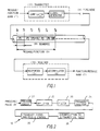
- Figure 1 shows an example of a simple communications system according to the present invention, in the form of a transmitter consisting of a compiler and a signal generator, a pipe or a hose whose medium transfers encoded signals, and a receiver consisting of a responder which reads the codes and allows these to be converted in a decompiler.
- Figure 2 shows a detailed functional diagram of a receiver where the variations in pressure are being detected, amplified, filtered and analysed with regard to the presence of Fourier-series frequency elements as well as their dating in time, and, following inspection and checking for validity, the signals are converted into alphanumeric data.
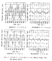
- Figure 3 shows the result of full-scale trials and analysis of sending, transmission and reception of complex frequency modulated signals.
- Figure 4 shows typical damping of frequency modulated sinusoidal pressure signals in pipes and hoses.
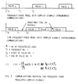
- Figure 5 shows algorithms for digital alphanumeric communication and the manner in which these, according to the present invention, will be transmitted through the medium in a pipe/hose.
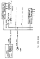
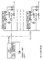
- Figure 6 shows a typical example of a Signal Pipe Bus.
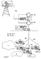
- Figure 7 shows a typical example of a Process Pipe Bus, wherein signals are communicated to and from the surface between stationary and mobile transmitters and receivers located in well branch valves, valve trees and mobile pipe pigs.
- Figure 8 shows a typical example of a Power Pipe Bus.
- Figure 9 illustrates the topological arrangement of a Well Bus System or Well Pipe Bus, wherein frequency modulated signals are transmitted in oil and/or gas to well branch pipes.
- Figure 1 shows a one-way communication system (simplex) which transmits and receives digital alphanumeric data.
- a two-way system (semi duplex) is obtained when the transmitter and receiver are combined in one unit and placed at either end of the pipe/the hose.
- transmitters/receivers 11, 12 may be positioned along a pipe/hose or in a pipe system with associated volume. A transmitter will then generally have a superior function of directing communication.
- the message 1 is established in digital alphanumeric format which may contain letters and figures.
- the compilator 2 converts the said alphanumeric data into frequency codes and corresponding algorithms. They govern the signal generator 3 which produces volume flow changes and of corresponding pressure profile in the connected pipe/hose 4.
- the pressure profiles or the amplitude of the signal may, depending on the damping and the amplifying properties of the pipe/hose system, vary from very low values to several tens of bars.
- the variation in the signal amplitudes will centre around the middle pressure of the pipe medium, and transfer at the speed of sound through the medium.
- the message 1 will be capable of being read by a number, in principle unlimited, of responders 5, arranged at the receiving side 12, but will only be decompiled in a decompilator 6 as a whole message 7 at addressed receivers.
- FIG 2 Shown in figure 2 is the detailed function of a receiver 12.
- the pressure variations in the system will at any time be recorded by a pressure sensitive element 21 and be amplified up into an amplifier 22 for further processing of the signal.
- the frequency modulated signal transmission will usually have a predetermined frequency band and pressure amplitudes, allowing any other noise to be filtered off in its entirety in a filter 23.
- time sequenced frequency elements are identified in a frequency analyser 24.
- Each receiver has one discrete and one common address (shared by several).
- the first and the last sequence in all messages are addresses.
- the initial address opens the reception at the addressee1 ⁇ 2s who receives all sequences until the final sequence which may be an address of another addressee. Sequences received will at once be made the subject of a signals analysis and checking in an inspection means 25 before the message is decompiled in a decompiler 26 into a uniform alphanumeric format.
- Shown in figure 5 is a preferred algorithm for frequency modulated pressure signals for alphanumeric communication in pipes/hoses.
- a frequency phase modulation with sequences of accessible frequencies within the same bandwidth will become very slow ⁇ 1 bit per second.
- a transmission rate at e.g. 50 Hz could be expected to increase to abt. 10 bits per second.
- figure 6 is shown the topological design of a possible Signal Pipe Bus system where frequency modulated signals are transmitted in a dedicated liquid or gas filled pipe/hose.
- the transmitters/receivers are here connected to digital governing and controlling logics for administration of local tasks in terms of technical instrumentation. Centrally placed main logic will normally direct and define priorities in the system1 ⁇ 2s communication.
- the operative interface may be connected to manual operation and/or an overall controlling system.
- FIG 7 is shown the topological design of a possible Process Pipe System where frequency modulated signals are transmitted through the same pipe(s)/hose(s) as a random process medium, in this case water, being injected into a well on the seabed.
- the functions are as for the Signal Pipe Bus.
- Figures 8 shows the topological design of a possible Power Pipe Bus system where frequency modulated signals are transmitted in the same pipe(s)/hose(s) as a random power medium, in this case hydraulic oil.
- the functions are as for the Signal Pipe Bus.
- Figure 9 illustrates the topological arrangement of a Well Bus System or Well Pipe Bus, wherein frequency modulated signals are transmitted in oil and/or gas to well branch pipes 30a, 30b, ... 30n, through appropriate valve control means 31a, 31b, ... 31n, respectively.
- the invention comprises the following main items:
Abstract
Description
- The present invention relates to a method for transferring signals through a medium in pipes, hoses and drilling holes, pressure impulses being generated at a transmitter side of various frequencies or in various frequency ranges.
- The present invention also relates to a transmitter and a receiver for transmitting as stated.
- Pressurised pipe systems generally have manoeuvring organs for valves as well as other types of instruments, inter alia for the recording of process variables which are inaccessible for operation by crew members. These functions are usually remotely controlled through pneumatic, hydraulic, electrical, telemetric and similar systems and devices.
- Frequently a combination of the above mentioned systems is used, in which the pneumatic/hydraulic power supply is controlled by electrically operated opening devices, with recording and feed-back of process variables through the same or through separate electrical cables.
- A typical example is remote control of subsea devices, connecting, via an umbilical with hydraulic tubes and electrical cables, the device with a vessel/platform.
- A version of this system is provided when electrical control and communication are replaced by cordless ether - telemetric or hydroacoustic communication of alphanumeric data. The device will then need to be capable of including its own power supply in the form of a battery or such like, to drive the instruments.
- Such systems utilise the ambient environment as the medium of transmission and are thus vulnerable to external disturbances.
- When they are used in controlling critical pneumatic and hydraulic functions, the requirements as to reliability, security and safety are therefore high. This consequently makes the systems very complicated and expensive.
- With subsea devices, furthermore, electrical conductors as well as ether and hydroacoustic telemetry systems have definite practical and physical limitations in the reliability obtainable and their possible range for safe and secure communication.
- A common feature of the systems mentioned is that by and large they represent an outside appurtenant auxiliary system, the purpose of which most often is to remotely control pneumatic and hydraulic primary functions.
- In terms of safety and security, both the auxiliary and the primary system are arranged for "Fail safe", i.e. upon occurrence of the most critical fatal system error, the system shall fail in security with the least possible dramatic outward consequences.
- In practice this means an unwanted close-down of one or several processes, which frequently represents large financial losses and increased danger to the outside environment.
- The most prominent error in the said auxiliary system is breakdowns in the communications line. Electrical cords here are sensitive to mechanical damage, insulation and couplings, in particular when these are submerged. Ether and hydroacoustic telemetry systems are easily influenced by movable objects in the communications line as well as by changes in the environment.
- Fatal errors in pneumatic and hydraulic primary systems are breakage and loss of power medium, whereupon the manoeuvring organs automatically via steel springs govern a controlled close-down of the process.
- Errors in the auxiliary systems are often arranged so that the pressurised driving medium in the primary systems is drained and causes a close-down of the process.
- It is also known that all remotely controlled pneumatic and hydraulic systems, except for directly controlled ones, introduce a further external auxiliary system running in parallel with the primary system. Such external systems thus by their physical existence, represent a quantified source of error.
- In connection with the production of oil and gas and the injection of water in the well system, there are often used one or more shut-off valves in a tree-system (well-head christmas tree) per drilling hole.
- The wellhead tree is at the upstream side anchored to an underground cemented pipe in the drilling hole leading down to the oil and gas reservoir, and represents together with a safety valve (SS CV) located usually 200 m below ground surface, a security barrier between the over-pressure in the reservoir and the external environment.
- Each point of the geometric lining of one or more reservoirs to be recovered, will thus be connected to a plurality of parallel sub-surface pipes.
- Each valve tree and sub-surface safety valve are operated from the surface and are under normal conditions controlled for opening, choking and closing.
- Usually, only a small number of drilling holes in a reservoir are used at a time, whereas the remaining production holes are shut down in the event of new accumulation of oil and gas.
- It is specific that the absence of adequate remote control technique for sub-surface located valves, will prevent reservoir complementation wherein a drilling hole through branch drilling and valves are used for reaching various points of the reservoir or an adjacent reservoir.
- The object of the present invention is to provide a system which constitutes an improvement relative to known systems, especially with regard to eliminating the error sources mentioned.
- This is achieved in a method of the kind stated in the preamble, which according to the invention is characterised in that the pressure pulses are generated at the transmission side as an organised and defined bit-pattern in order thereby to obtain one- or two-way alphanumeric communication.
- With the invention concerned, therefore, it is possible to utilise the liquid and the gas inside the pipe of a primary system in transmitting alphanumeric communication for tasks of a technical instrumentation nature in a controlled, defined, safe and secure environment.
- Alternatively, pipe connections for such communication may be dedicated to such transmission of signals, may have other process related main purposes, or constitute combined power medium and signal supply.
- The present invention thus relates to a system for cordless transmission of alphanumeric data, where signals are transferred through pipes or hoses filled with gas and liquid, as defined encoded pressure pulses.
- The invention relates to a method for defining and encoding pressure pulses which increase the accessible bandwidth and digital transmission rate.
- Against this background, corresponding descriptions emerge for the invention according to the attached claims, namely Signal Pipe Bus, Process Pipe Bus, Power Pipe Bus, and Well Pipe Bus.
- The concept "Bus" in this connection comprises the communication lines in a closed system of pipes/hoses with pertaining volume, wherein one or several transmitters and receivers exchange data according to an organised and defined pattern. Such communication may typically comprise messages for controlling, recording, and diagnosing equipment and processes.
- It is known that various devices exist which use medium in pipelines to control and feed back process variables. Examples thereof are frequency governed valves, NO patent 158.232 and drilling equipment MWD patent US-A-4.914.637.
- Common to these is that they respectively respond to or generate exclusively discrete frequency modulated pressure pulses for a one-way communication line. They do 5 not employ any kind of organised and defined bit-pattern for one- or two-way alphanumeric communication.
- Frequency modulated pressure pulses transferred through media in pipes are subject to marked damping which is among other things due to signal frequency, the material, diameter and length of the pipe, as well as the properties of the medium.
- Higher frequencies are always dampened more rapidly than low ones. In ordinarily dimensioned systems for pneumatics and hydraulics, the usable bandwidth will in practice lie in the range from 0 to 50 Hz.
- At such low frequencies and narrow bandwidth, the possible scope, content and actuality for a relevant communication would be severely restricted.
- According to the invention, however, the usable bandwidth for pipe systems with high damping may be extended by the use of complex signals. Here the accessible single frequencies are combined together in groups of two or several frequencies in a simultaneous transmission.
- In this manner, the bandwidth which can be utilised will be multiplied as required and realise a formerly unknown potential of possible communication in most pipe dimensions.
- Additional advantages and features of the invention will be described in greater detail below under reference to the attached drawings.
- Figure 1 shows an example of a simple communications system according to the present invention, in the form of a transmitter consisting of a compiler and a signal generator, a pipe or a hose whose medium transfers encoded signals, and a receiver consisting of a responder which reads the codes and allows these to be converted in a decompiler.
- Figure 2 shows a detailed functional diagram of a receiver where the variations in pressure are being detected, amplified, filtered and analysed with regard to the presence of Fourier-series frequency elements as well as their dating in time, and, following inspection and checking for validity, the signals are converted into alphanumeric data.
- Figure 3 shows the result of full-scale trials and analysis of sending, transmission and reception of complex frequency modulated signals.
- Figure 4 shows typical damping of frequency modulated sinusoidal pressure signals in pipes and hoses.
- Figure 5 shows algorithms for digital alphanumeric communication and the manner in which these, according to the present invention, will be transmitted through the medium in a pipe/hose.
- Figure 6 shows a typical example of a Signal Pipe Bus.
- Figure 7 shows a typical example of a Process Pipe Bus, wherein signals are communicated to and from the surface between stationary and mobile transmitters and receivers located in well branch valves, valve trees and mobile pipe pigs.
- Figure 8 shows a typical example of a Power Pipe Bus.
- Figure 9 illustrates the topological arrangement of a Well Bus System or Well Pipe Bus, wherein frequency modulated signals are transmitted in oil and/or gas to well branch pipes.
- Figure 1 shows a one-way communication system (simplex) which transmits and receives digital alphanumeric data.
- A two-way system (semi duplex) is obtained when the transmitter and receiver are combined in one unit and placed at either end of the pipe/the hose.
- Several transmitters/
receivers - The
message 1 is established in digital alphanumeric format which may contain letters and figures. Thecompilator 2 converts the said alphanumeric data into frequency codes and corresponding algorithms. They govern thesignal generator 3 which produces volume flow changes and of corresponding pressure profile in the connected pipe/hose 4. - The pressure profiles or the amplitude of the signal may, depending on the damping and the amplifying properties of the pipe/hose system, vary from very low values to several tens of bars.
- The variation in the signal amplitudes will centre around the middle pressure of the pipe medium, and transfer at the speed of sound through the medium.
- The
message 1 will be capable of being read by a number, in principle unlimited, ofresponders 5, arranged at the receivingside 12, but will only be decompiled in adecompilator 6 as awhole message 7 at addressed receivers. - Shown in figure 2 is the detailed function of a
receiver 12. The pressure variations in the system will at any time be recorded by a pressuresensitive element 21 and be amplified up into anamplifier 22 for further processing of the signal. The frequency modulated signal transmission will usually have a predetermined frequency band and pressure amplitudes, allowing any other noise to be filtered off in its entirety in afilter 23. There-after, time sequenced frequency elements are identified in afrequency analyser 24. Each receiver has one discrete and one common address (shared by several). - The first and the last sequence in all messages are addresses. The initial address opens the reception at the addressee½s who receives all sequences until the final sequence which may be an address of another addressee. Sequences received will at once be made the subject of a signals analysis and checking in an inspection means 25 before the message is decompiled in a
decompiler 26 into a uniform alphanumeric format. - From figure 3 it is evident how individual frequency modulated sinusoidal pressure signals may be put together to form a complex signal as an element in a Fourier-series. Furthermore, the result from a full-scale testing shows that substantially the same damping is achieved as if each element of the complex signal were to have been the subject of separate transmission.
- This entails that complexly designed sinusoidal pressure signals are not distorted and may be decomposed for an intelligent utilisation of programmed information content.
- It is shown in figure 4 that frequency modulated sinusoidal pressure signals are strongly amplified and dampened depending on the physical properties and nature of the system concerned.
- Practical tests in existing pipe systems show that the resonance and pressure reflections of some pipe systems may block off a stable transmission of signals.
- This is overcome by implementing relevantly dimensioned accumulators as required.
- Shown in figure 5 is a preferred algorithm for frequency modulated pressure signals for alphanumeric communication in pipes/hoses.
- A mere time modulation of signals similar to that of morse will at e.g. a bandwidth of 50 Hz give inappropriately cumbersome and slow communication.
- Similarly, a frequency phase modulation (synchronous communication) with sequences of accessible frequencies within the same bandwidth will become very slow < 1 bit per second. By introducing complex frequency modulated signals in a frequency phase model (synchronous communication) a transmission rate at e.g. 50 Hz could be expected to increase to abt. 10 bits per second.
- In the above transmission concept is combined in a time phase frequency model, where complex signals are included, satisfactory communication up to abt. 20 bits per second may be expected at the same bandwidth.
- In figure 6 is shown the topological design of a possible Signal Pipe Bus system where frequency modulated signals are transmitted in a dedicated liquid or gas filled pipe/hose.
- The transmitters/receivers are here connected to digital governing and controlling logics for administration of local tasks in terms of technical instrumentation. Centrally placed main logic will normally direct and define priorities in the system½s communication. The operative interface may be connected to manual operation and/or an overall controlling system.
- In figure 7 is shown the topological design of a possible Process Pipe System where frequency modulated signals are transmitted through the same pipe(s)/hose(s) as a random process medium, in this case water, being injected into a well on the seabed. The functions are as for the Signal Pipe Bus.
- Figures 8 shows the topological design of a possible Power Pipe Bus system where frequency modulated signals are transmitted in the same pipe(s)/hose(s) as a random power medium, in this case hydraulic oil. The functions are as for the Signal Pipe Bus.
- Figure 9 illustrates the topological arrangement of a Well Bus System or Well Pipe Bus, wherein frequency modulated signals are transmitted in oil and/or gas to
well branch pipes - The invention comprises the following main items:
- 1. A transmitter/
receiver system alphanumeric communication 1, where encoded signals are transferred through liquid and gas in pipes and hoses with associated volume, with randomly placed transmitters compiling 2 and generatingsignals 3, and receivers recording 25 and decompiling 26 the signals into alphanumeric data, the signals being transferred through pipe/hose systems 4 which may have various main functions and contain set volumes of different sizes consisting of liquid, gas or a mixture thereof. - 2. A method for increasing the accessible signal band-width by employing two or several frequency components in a Fourier-series in a time and
frequency phase modulation 1, the sum of available codes/symbols being increased exponentially with the number of complex combinations used, and an increased communication rate being achieved, expressed in bits per second. - 3. A communication system which may be described as Signal Pipe Bus where gas or liquid filled dedicated pipes and hoses with associated volume(s) are used in transferring the signals.
- 4. A communication system which may be described as Process Pipe Bus where randomly functioning gas or liquid filled pipes and hoses with associated volume(s) are used in transferring the signals.
- 5. A communication system which may be described as Power Pipe Bus where gas or liquid in pipes and hoses belonging to a power system, are used in transferring the signals.
- 6. A communication system which can be designed as a Well Bus System, wherein the produced gas and/or oil from the reservoir is used for transmission of signals.
- 7. A system for
alphanumeric communication 1 where compileddata 2 are transferred to asignals generator 3generating sequences 8 of frequency modulated changes in volume flows the corresponding pressure changes of which are being transferred through gas and liquid filled pipes/hoses 4 to randomly placedresponders 5 withaddress 10, the frequency modulation consisting of a method wheresequences 8 of a defined pressure profile put together from one or several frequency components, which in themselves or through their periodic duration, represent a defined code/symbol in a message/function 9, theresponder 5 recording transmitted codes which are being decompiled 6 for definition of communicated messages/functions 7, please see in particular figure 1.
Claims (16)
- A method for transferring signals through a medium in pipes, hoses and drilling holes, pressure pulses of various frequencies or in various frequency ranges being generated at a transmitter side,
characterised in that the pressure pulses are generated at the transmitter side as an organised and defined bit-pattern in order thereby to achieve one or two-way alphanumeric communication. - A method as stated in claim 1,
characterised in that the pressure pulses are generated at the transmitter side as complex frequency modulated pressure pulses, e.g. by combining single frequencies into groups of two or several frequencies in simultaneous transmission. - A method as stated in claims 1 or 2,
characterised in that the pressure pulses are generated as frequency modulated pressure pulses by using two or more frequency components in a Fourier-series in a time and frequency phase modulation in order thereby to achieve that the sum of available codes/symbols is increased exponentially with the number of complex combinations used, and to achieve an increased communication rate expressed in bit/s. - A method as stated in one of the preceding claims,
characterised in that at the transmitter side, single frequency modulated sinusoidal pressure signals are generated which are put together into a complex signal as an element in a Fourier-series which entails substantially equal damping as if each element of the complex signal were to have been the subject of separate transmission, and damping at optimal signal compression for ensuing decomposing for utilisation of compression for ensuing decomposing for utilisation of programmed information content. - A method for the reception of signals through a medium in pipes, hoses and drilling holes, pressure pulses of various frequencies or in various frequency ranges being generated at a transmitter side, as stated in any of the claims 1 to 5,
characterised in that at the receiver side, pressure pulses are received and decoded which at the transmitter side are generated as an organised and defined bit pattern, in order thereby to achieve one or two-way alphanumeric communication. - A method as stated-in any of the preceding claims,
characterised in that the signals are transferred through a pipe/hose/drilling hole system which may have various main functions and may contain bound volumes of different sizes comprising liquid, gas or a mixture thereof. - A method as stated in any of the preceding claims,
characterised in that the method is part of a system which may be described as signal pipe bus, where gas or liquid filled pipes, hoses and drilling holes with associated volume(s) are used preferably in transferring the signals. - A method as stated in any of the preceding claims,
characterised in that the method is part of a communication system which may be described as process pipe bus, where randomly functioning gas or liquid filled pipes, hoses and drilling holes with associated volume(s) are used in transferring the signals. - A method as stated in any of the preceding claims,
characterised in that the method is part pipe bus, where gas or liquid in pipes, hoses and drilling holes belonging to a power supply are used in transferring the signals. - A method as stated in any of the preceding claims,
characterised in that pressure profiles or signal amplitudes are provided, depending on the damping or amplifying properties of the hose system. - A method as stated in any of the preceding claims,
characterised in that a pipe system is employed which comprises implemented relevantly dimensioned accumulators related to the resonance and pressure reflections of the pipe system. - A transmitter for a system for transferring signals through a medium in pipes, hoses and drilling holes, comprising a generator for generating pressure pulses of various frequencies or in various frequency ranges,
characterised in that the transmitter (11) furthermore comprises a compiler (2) which converts a bit pattern into frequency codes, and that the signal generator (3) generates corresponding pressure profiles in associated pipes/hoses/drilling holes in order thereby to achieve one or two-way alphanumeric communication. - A receiver for a system for transferring signals through a medium in pipes or hoses or drilling holes, the signals being transferred as generated pressure pulses of various frequencies or in various frequency ranges, in particular in connection with a transmitter as stated in claim 12, the said receiver comprising a pressure sensor and an amplifier, characterised in that the receiver (12) furthermore comprises a filter (23) which allows through a predefined frequency band and pressure amplitudes, a frequency analyser (24) which identifies time sequenced frequency elements, and that the receiver may perhaps comprise a distinct and/or a common address.
- A receiver as stated in claim 13,
characterised in that the receiver (12) furthermore comprises an inspection means (25) which checks the frequency analysis performed in the frequency analyser (24), as well as a decompilator (26) which decompiles the pressure frequency modulated message into a bit pattern, i.e. an alphanumeric message. - A receiver and a transmitter as stated in any of the claims 12-14, characterised in that the receiver and the transmitter constitute part of a two-way system (semi duplex) where the transmitter and the receiver are combined in one unit and positioned at either end of the pipe/hose/drilling hole.
- A transmitter and a receiver as stated in any of the claims 12-14, characterised in that a multitude of transmitters/receivers is placed along or inside a pipe or a hose or a drilling hole or in a pipe system with associated volume(s), and that a transmitter may possibly have a superior task in directing the communication.
Applications Claiming Priority (2)
| Application Number | Priority Date | Filing Date | Title |
|---|---|---|---|
| NO940952 | 1994-03-16 | ||
| NO940952A NO305219B1 (en) | 1994-03-16 | 1994-03-16 | Method and transmitter / receiver for transmitting signals via a medium in tubes or hoses |
Publications (2)
| Publication Number | Publication Date |
|---|---|
| EP0672819A2 true EP0672819A2 (en) | 1995-09-20 |
| EP0672819A3 EP0672819A3 (en) | 1997-08-13 |
Family
ID=19896936
Family Applications (1)
| Application Number | Title | Priority Date | Filing Date |
|---|---|---|---|
| EP95610008A Withdrawn EP0672819A3 (en) | 1994-03-16 | 1995-03-14 | Method and transmitter/receiver for transferring signals through a medium in pipes and hoses. |
Country Status (5)
| Country | Link |
|---|---|
| US (1) | US5546359A (en) |
| EP (1) | EP0672819A3 (en) |
| JP (1) | JPH07288505A (en) |
| BR (1) | BR9501089A (en) |
| NO (1) | NO305219B1 (en) |
Cited By (4)
| Publication number | Priority date | Publication date | Assignee | Title |
|---|---|---|---|---|
| US6018501A (en) * | 1997-12-10 | 2000-01-25 | Halliburton Energy Services, Inc. | Subsea repeater and method for use of the same |
| US6075461A (en) * | 1997-12-29 | 2000-06-13 | Halliburton Energy Services, Inc. | Disposable electromagnetic signal repeater |
| US6384738B1 (en) | 1997-04-07 | 2002-05-07 | Halliburton Energy Services, Inc. | Pressure impulse telemetry apparatus and method |
| US6388577B1 (en) | 1997-04-07 | 2002-05-14 | Kenneth J. Carstensen | High impact communication and control system |
Families Citing this family (13)
| Publication number | Priority date | Publication date | Assignee | Title |
|---|---|---|---|---|
| US6172614B1 (en) | 1998-07-13 | 2001-01-09 | Halliburton Energy Services, Inc. | Method and apparatus for remote actuation of a downhole device using a resonant chamber |
| US6450263B1 (en) | 1998-12-01 | 2002-09-17 | Halliburton Energy Services, Inc. | Remotely actuated rupture disk |
| DE19942508A1 (en) * | 1999-09-07 | 2001-03-15 | Festo Ag & Co | Method and device for transmitting control and / or sensor signals |
| JP2003042400A (en) * | 2001-08-01 | 2003-02-13 | Sony Corp | Information transfer device |
| US6909667B2 (en) * | 2002-02-13 | 2005-06-21 | Halliburton Energy Services, Inc. | Dual channel downhole telemetry |
| JP4238264B2 (en) * | 2004-03-09 | 2009-03-18 | 株式会社根本杏林堂 | Chemical solution injection device and fluoroscopic imaging device |
| US20100133004A1 (en) * | 2008-12-03 | 2010-06-03 | Halliburton Energy Services, Inc. | System and Method for Verifying Perforating Gun Status Prior to Perforating a Wellbore |
| US8697486B2 (en) | 2009-04-15 | 2014-04-15 | Micro Technology, Inc. | Methods of forming phase change materials and methods of forming phase change memory circuitry |
| US10508937B2 (en) * | 2012-04-12 | 2019-12-17 | Texas Instruments Incorporated | Ultrasonic flow meter |
| US9535039B2 (en) | 2014-04-30 | 2017-01-03 | Control Devices, Inc. | Acoustic transmitter and method for underwater pipeline inspection gauges |
| US10177858B2 (en) * | 2015-10-02 | 2019-01-08 | Texas Instruments Incorporated | Minimum tone separation constrained MFSK scheme for ultrasonic communications |
| GB2605542B (en) | 2019-12-18 | 2023-11-01 | Baker Hughes Oilfield Operations Llc | Oscillating shear valve for mud pulse telemetry and operation thereof |
| WO2021247673A1 (en) | 2020-06-02 | 2021-12-09 | Baker Hughes Oilfield Operations Llc | Angle-depending valve release unit for shear valve pulser |
Citations (6)
| Publication number | Priority date | Publication date | Assignee | Title |
|---|---|---|---|---|
| US3309656A (en) * | 1964-06-10 | 1967-03-14 | Mobil Oil Corp | Logging-while-drilling system |
| US3789355A (en) * | 1971-12-28 | 1974-01-29 | Mobil Oil Corp | Method of and apparatus for logging while drilling |
| US4045767A (en) * | 1972-09-20 | 1977-08-30 | Hitachi, Ltd. | Method of ultrasonic data communication and apparatus for carrying out the method |
| US4787093A (en) * | 1983-03-21 | 1988-11-22 | Develco, Inc. | Combinatorial coded telemetry |
| US5055837A (en) * | 1990-09-10 | 1991-10-08 | Teleco Oilfield Services Inc. | Analysis and identification of a drilling fluid column based on decoding of measurement-while-drilling signals |
| EP0617196A2 (en) * | 1993-03-26 | 1994-09-28 | Halliburton Company | Digital mud pulse telemetry system |
Family Cites Families (10)
| Publication number | Priority date | Publication date | Assignee | Title |
|---|---|---|---|---|
| US3863203A (en) * | 1972-07-18 | 1975-01-28 | Mobil Oil Corp | Method and apparatus for controlling the data rate of a downhole acoustic transmitter in a logging-while-drilling system |
| US4027282A (en) * | 1974-10-18 | 1977-05-31 | Texas Dynamatics, Inc. | Methods and apparatus for transmitting information through a pipe string |
| US4078620A (en) * | 1975-03-10 | 1978-03-14 | Westlake John H | Method of and apparatus for telemetering information from a point in a well borehole to the earth's surface |
| US4007331A (en) * | 1975-08-13 | 1977-02-08 | Bunker Ramo Corporation | Apparatus for demodulation of relative phase modulated binary data |
| GB2156878A (en) * | 1984-03-30 | 1985-10-16 | Nl Industries Inc | Encoding and transmission system for mud pulse telemetry of tool face angle data |
| CA1268052A (en) * | 1986-01-29 | 1990-04-24 | William Gordon Goodsman | Measure while drilling systems |
| US4797668A (en) * | 1986-12-12 | 1989-01-10 | Halliburton Company | Acoustic well logging system having multiplexed filter digitizing |
| US4847815A (en) * | 1987-09-22 | 1989-07-11 | Anadrill, Inc. | Sinusoidal pressure pulse generator for measurement while drilling tool |
| US5128901A (en) * | 1988-04-21 | 1992-07-07 | Teleco Oilfield Services Inc. | Acoustic data transmission through a drillstring |
| US5148408A (en) * | 1990-11-05 | 1992-09-15 | Teleco Oilfield Services Inc. | Acoustic data transmission method |
-
1994
- 1994-03-16 NO NO940952A patent/NO305219B1/en not_active IP Right Cessation
-
1995
- 1995-03-14 EP EP95610008A patent/EP0672819A3/en not_active Withdrawn
- 1995-03-15 BR BR9501089A patent/BR9501089A/en not_active IP Right Cessation
- 1995-03-15 JP JP7081996A patent/JPH07288505A/en active Pending
- 1995-03-15 US US08/404,316 patent/US5546359A/en not_active Expired - Lifetime
Patent Citations (6)
| Publication number | Priority date | Publication date | Assignee | Title |
|---|---|---|---|---|
| US3309656A (en) * | 1964-06-10 | 1967-03-14 | Mobil Oil Corp | Logging-while-drilling system |
| US3789355A (en) * | 1971-12-28 | 1974-01-29 | Mobil Oil Corp | Method of and apparatus for logging while drilling |
| US4045767A (en) * | 1972-09-20 | 1977-08-30 | Hitachi, Ltd. | Method of ultrasonic data communication and apparatus for carrying out the method |
| US4787093A (en) * | 1983-03-21 | 1988-11-22 | Develco, Inc. | Combinatorial coded telemetry |
| US5055837A (en) * | 1990-09-10 | 1991-10-08 | Teleco Oilfield Services Inc. | Analysis and identification of a drilling fluid column based on decoding of measurement-while-drilling signals |
| EP0617196A2 (en) * | 1993-03-26 | 1994-09-28 | Halliburton Company | Digital mud pulse telemetry system |
Cited By (7)
| Publication number | Priority date | Publication date | Assignee | Title |
|---|---|---|---|---|
| US6384738B1 (en) | 1997-04-07 | 2002-05-07 | Halliburton Energy Services, Inc. | Pressure impulse telemetry apparatus and method |
| US6388577B1 (en) | 1997-04-07 | 2002-05-14 | Kenneth J. Carstensen | High impact communication and control system |
| US6710720B2 (en) | 1997-04-07 | 2004-03-23 | Halliburton Energy Services, Inc. | Pressure impulse telemetry apparatus and method |
| US6760275B2 (en) | 1997-04-07 | 2004-07-06 | Kenneth J. Carstensen | High impact communication and control system |
| US7295491B2 (en) | 1997-04-07 | 2007-11-13 | Carstensen Kenneth J | High impact communication and control system |
| US6018501A (en) * | 1997-12-10 | 2000-01-25 | Halliburton Energy Services, Inc. | Subsea repeater and method for use of the same |
| US6075461A (en) * | 1997-12-29 | 2000-06-13 | Halliburton Energy Services, Inc. | Disposable electromagnetic signal repeater |
Also Published As
| Publication number | Publication date |
|---|---|
| BR9501089A (en) | 1995-11-07 |
| NO940952L (en) | 1995-09-18 |
| NO940952D0 (en) | 1994-03-16 |
| NO305219B1 (en) | 1999-04-19 |
| JPH07288505A (en) | 1995-10-31 |
| EP0672819A3 (en) | 1997-08-13 |
| US5546359A (en) | 1996-08-13 |
Similar Documents
| Publication | Publication Date | Title |
|---|---|---|
| US5546359A (en) | Method and transmitter/receiver for transferring signals through a medium in pipes and hoses | |
| CN101015147B (en) | Downhole telemetry system for wired tubing | |
| US20120275274A1 (en) | Acoustic transponder for monitoring subsea measurements from an offshore well | |
| EP1812683B1 (en) | System and method for wireless communication in a producing well system | |
| US6880634B2 (en) | Coiled tubing acoustic telemetry system and method | |
| CA2138147C (en) | Data transmission on undersea pipelines | |
| US6018501A (en) | Subsea repeater and method for use of the same | |
| US20120294114A1 (en) | Acoustic telemetry of subsea measurements from an offshore well | |
| US6218959B1 (en) | Fail safe downhole signal repeater | |
| US20050241710A1 (en) | Apparatus for pipeline isolation | |
| US7445042B2 (en) | Signalling method and apparatus | |
| US9435908B2 (en) | Wireless subsea monitoring and control system | |
| MXPA04005543A (en) | Burst qam downhole telemetry system. | |
| NO319695B1 (en) | Electromagnetic signal amplifier device and method for communicating information between equipment immersed in a wellbore and equipment on the surface | |
| US20150077265A1 (en) | Telemetry on tubing | |
| WO2017085442A1 (en) | Communication system network | |
| US10246994B2 (en) | System for communicating data via fluid lines | |
| US9042200B2 (en) | Downhole telemetry system | |
| US6933856B2 (en) | Adaptive acoustic transmitter controller apparatus and method | |
| EP2876256A1 (en) | Communication path verification for downhole networks | |
| Nassereddin et al. | Electromagnetic Surface-Controlled Sub-Surface Safety Valve: An Immediate Solution to Secure Wells with Damaged Control Line | |
| US20150102938A1 (en) | Downhole Short Wavelength Radio Telemetry System for Intervention Applications | |
| CN107888296A (en) | Utilize the communication system and method for pipeline configuration | |
| Green | Command and Control of Subsea Well Completions by means of Acoustic Communications | |
| Eck et al. | High speed digital acoustic telemetry system |
Legal Events
| Date | Code | Title | Description |
|---|---|---|---|
| PUAI | Public reference made under article 153(3) epc to a published international application that has entered the european phase |
Free format text: ORIGINAL CODE: 0009012 |
|
| AK | Designated contracting states |
Kind code of ref document: A2 Designated state(s): AT BE CH DE FR GB IT LI LU NL SE |
|
| PUAL | Search report despatched |
Free format text: ORIGINAL CODE: 0009013 |
|
| RHK1 | Main classification (correction) |
Ipc: E21B 47/18 |
|
| AK | Designated contracting states |
Kind code of ref document: A3 Designated state(s): AT BE CH DE FR GB IT LI LU NL SE |
|
| 17P | Request for examination filed |
Effective date: 19971016 |
|
| 17Q | First examination report despatched |
Effective date: 20000316 |
|
| STAA | Information on the status of an ep patent application or granted ep patent |
Free format text: STATUS: THE APPLICATION IS DEEMED TO BE WITHDRAWN |
|
| 18D | Application deemed to be withdrawn |
Effective date: 20011002 |