EP0675179A2 - Image forming method, and ink set and ink-jet machinery used therein - Google Patents
Image forming method, and ink set and ink-jet machinery used therein Download PDFInfo
- Publication number
- EP0675179A2 EP0675179A2 EP95104651A EP95104651A EP0675179A2 EP 0675179 A2 EP0675179 A2 EP 0675179A2 EP 95104651 A EP95104651 A EP 95104651A EP 95104651 A EP95104651 A EP 95104651A EP 0675179 A2 EP0675179 A2 EP 0675179A2
- Authority
- EP
- European Patent Office
- Prior art keywords
- ink
- set according
- liquid composition
- inks
- ink set
- Prior art date
- Legal status (The legal status is an assumption and is not a legal conclusion. Google has not performed a legal analysis and makes no representation as to the accuracy of the status listed.)
- Granted
Links
Images

Classifications
-
- C—CHEMISTRY; METALLURGY
- C09—DYES; PAINTS; POLISHES; NATURAL RESINS; ADHESIVES; COMPOSITIONS NOT OTHERWISE PROVIDED FOR; APPLICATIONS OF MATERIALS NOT OTHERWISE PROVIDED FOR
- C09D—COATING COMPOSITIONS, e.g. PAINTS, VARNISHES OR LACQUERS; FILLING PASTES; CHEMICAL PAINT OR INK REMOVERS; INKS; CORRECTING FLUIDS; WOODSTAINS; PASTES OR SOLIDS FOR COLOURING OR PRINTING; USE OF MATERIALS THEREFOR
- C09D11/00—Inks
- C09D11/30—Inkjet printing inks
- C09D11/40—Ink-sets specially adapted for multi-colour inkjet printing
-
- B—PERFORMING OPERATIONS; TRANSPORTING
- B41—PRINTING; LINING MACHINES; TYPEWRITERS; STAMPS
- B41J—TYPEWRITERS; SELECTIVE PRINTING MECHANISMS, i.e. MECHANISMS PRINTING OTHERWISE THAN FROM A FORME; CORRECTION OF TYPOGRAPHICAL ERRORS
- B41J2/00—Typewriters or selective printing mechanisms characterised by the printing or marking process for which they are designed
- B41J2/005—Typewriters or selective printing mechanisms characterised by the printing or marking process for which they are designed characterised by bringing liquid or particles selectively into contact with a printing material
- B41J2/01—Ink jet
Definitions
- This invention relates to an image forming method, and an ink set and an ink-jet machinery that are used therein.
- Ink-jet recording is a process of making a record by causing minute droplets of ink to fly and adhere to a recording medium such as paper.
- a recording medium such as paper.
- methods as disclosed in Japanese Patent Publications No. 61-59911, No. 61-59912 and No. 61-59914 in which a heat energy is imparted to ink by using an electrothermal transducer as an ejection energy feeding means enable easy materialization of higher-density multi-orifice recording head and hence images with a high resolution and a high quality can be recorded at a high speed.
- inks conventionally used in ink-jet recording are commonly mainly composed of water and to which water-soluble high-boiling solvents such as glycol are added for the purposes of, e.g., preventing inks from drying and preventing orifices from clogging.
- water-soluble high-boiling solvents such as glycol
- Japanese Patent Application Laid-open No. 55-65269 discloses adding to ink a compound capable of increasing its permeation.
- Japanese Patent Application Laid-open No. 55-66976 also discloses use of an ink mainly composed of a volatile solvent.
- coloring materials also permeate into the recording paper to a great depth together with ink to cause inconveniences such as a lowering of an image density and chroma and also cause a spread of ink in the lateral direction, which consequently may also cause the problems of a decrease in edge sharpness and a lowering of resolution.
- clogging due to evaporation of solvents undesirably tends to occur at nozzles of the recording head.
- Japanese Patent Application Laid-open No. 63-299971 discloses a method in which a liquid containing an organic compound having at least two cationic groups per molecule are made to adhere to the recording medium and thereafter the recording is carried out using an ink containing an anionic dye.
- Japanese Patent Application Laid-open No. 64-9279 also discloses a method in which an acidic liquid containing succinic acid or the like is made to adhere and thereafter the recording is carried out using an ink containing an anionic dye.
- Japanese Patent Application Laid-open No. 64-63185 also discloses a method in which a liquid that can make dyes insoluble is imparted before the ink is imparted to carry out recording.
- the pronzing tends to occur also in the case of process black formed by mixture of yellow, cyan and magenta three colors.
- an object of the present invention is to settle the following four technical subjects.
- the present invention provides an ink set comprising a combination of a liquid composition containing a cationic substance, with a yellow ink, a cyan ink and a magenta ink, wherein; the three inks each contain a water-soluble anionic dye and are capable of affording a chromaticity CIE L*a*b* to a black image presented on a recording medium by using these inks in combination within the range of the numerical expressions: 10 ⁇ L* ⁇ 30, 0 ⁇ a* ⁇ 7, and -10 ⁇ b* ⁇ 0.
- the present invention also provides an image forming method comprising forming a black portion by using a liquid composition containing a cationic substance, in combination with a yellow ink, a cyan ink and a magenta ink, wherein; the three inks each contain a water-soluble anionic dye and are capable of affording a chromaticity CIE L*a*b* to a black image presented on a recording medium by using these inks in combination within the range of the numerical expressions: 10 ⁇ L* ⁇ 30, 0 ⁇ a* ⁇ 7, and -10 ⁇ b* ⁇ 0.
- the present invention still provides an image forming method comprising imparting a liquid composition, a yellow ink, a cyan ink and a magenta ink by an ink-jet system to record a black portion, wherein the ink set described above is applied.
- the present invention still also provides a recording unit comprising holders for a liquid composition and an ink and a head for ejecting the liquid composition and the ink in the form of droplets, wherein the ink set described above is applied.
- the present invention further provides an ink cartridge comprising holders for a liquid composition and an ink, wherein the ink set described above is applied.
- the present invention still further provides an ink-jet recording apparatus comprising the recording unit described above.
- the present invention still further provides an ink-jet recording apparatus comprising the ink cartridge described above.
- the present invention still further provides an image which is presented using a liquid composition containing a cationic substance, in combination with a yellow ink, a cyan ink and a magenta ink, and contains a black portion having on a recording medium a chromaticity CIE L*a*b* within the range of the numerical expressions: 10 ⁇ L* ⁇ 30, 0 ⁇ a* ⁇ 7, and -10 ⁇ b* ⁇ 0.
- Fig. 1 illustrates a longitudinal cross section of a head assembly of an ink-jet recording apparatus.
- Fig. 2 is a transverse cross section of the head assembly of an ink-jet recording apparatus.
- Fig. 3 is a perspective illustration of the appearance of another head assembly of an ink-jet recording apparatus.
- Fig. 4 is a perspective illustration of an example of an ink-jet recording apparatus.
- Fig. 5 is a vertical cross-sectional illustration of an ink cartridge.
- Fig. 6 is a perspective illustration of a recording unit.
- the liquid composition and inks mentioned above are mixed at the part where they have permeated into a recording paper.
- the cationic substance and the anionic groups contained in the inks electrostatically combine to cause instantaneous aggregation, and the dye components and solvent components in the inks become separate (hereinafter this phenomenon is called solid-liquid separation), so that only the solvent components permeate into the recording paper and hence the coloring material, dye components, cause no bleeding.
- the molecular weight referred to in the present invention means a number average molecular weight, which is measured by methods such as GPC (gel permeation chromatography).
- the low-molecular weight component of the cationic substance contained in the liquid composition and the water-soluble dye having anionic groups used in the ink ionically act on each other to cause association, which causes instantaneous separation from the liquid phase.
- the product of the above association between the dye and the low-molecular weight cationic substances is adsorbed by the high-molecular weight component and hence the size of dye aggregates produced upon the association further increases, so that they become difficult to enter into the gaps between fibers of the recording paper.
- the liquid having undergone solid-liquid separation permeates into the recording paper and hence both the character quality level and the fixing performance can be achieved.
- the aggregates formed of the low-molecular weight component, the anionic dye and the cationic substance, produced by the mechanism as explained above come to have a large viscosity and do not move with the movement of the liquid medium. Hence, no edge sharpness of characters or images is damaged even when the fixing is accelerated as in the prior art, and a good character quality level can be obtained.
- the above aggregates are also substantially water-insoluble and hence the water resistance of the images formed becomes perfect.
- the aggregates may cause crystallization on the recording paper, where, especially when the ink is black, the prints may have a reddish color tone and can not become black depending on differences in the concentration of dyes in the ink, the type of dyes, the quantity of ink ejection and the type of paper. This phenomenon has been similarly questioned also in the case of process black formed by mixture of yellow, cyan and magenta three colors.
- the liquid composition will be first described.
- the essential component to be contained in the liquid composition referred to in the present invention is the cationic substance.
- the function of the cationic substance in the present invention is to electrostatically combine with the water-soluble anionic dye contained in ink, described later, to form aggregates.
- the cationic substance comprises the following two components as mentioned above.
- component (1) low-molecular weight cationic substance with a molecular weight of 1,000 or less are shown below.
- Primary, secondary and tertiary amine salt compounds specifically including hydrochlorides or acetates of lauryl amine, coconut amine, stearyl amine and rosin amine; quaternary ammonium salt compounds specifically including lauryltrimethylammonium chloride, lauryldimethylbenzylammonium chloride, benzyltributylammonium chloride and benzalkonium chloride; pyridinium salt compounds specifically including cetylpyridinium chloride and cetylpyridinium bromide; imidazoline type cationic compounds specifically including 2-butadecenyl-hydroxyethylimidazoline; and ethylene oxide addition products of higher alkylamines, specifically including hydroxyethylstearylamine.
- amphoteric surface active agents having cationic properties in a certain pH range can also be used. They may more specifically including amino acid type amphoteric surface active agents, and carboxylate type amphoteric surface active agents such as R-NH-CH2-CH2-COOH type compounds and betaine type compounds, specifically including stearyldimethylbetaine and lauryldihydroxyethylbetaine, as well as sulfuric ester type, sulfonic acid type and phosphoric ester type amphoteric surface active agents.
- the liquid composition must be prepared so as to have a pH not higher than their isoelectric points, or must be adjusted so as to have a pH not higher than the isoelectric points upon its mixture with inks on the recording medium, either means of which may be taken.
- the low-molecular weight cationic compounds are as exemplified above. Needless to say, the compounds that can be used in the present invention are by no means limited to these.
- component (1) monomers or oligomers of the cationic high-molecular weight component described later may also be used.
- Examples of the low-molecular weight cationic substance with a molecular weight of 1,000 or less are as shown above.
- those having a molecular weight ranging from 100 to 700 are particularly preferred in view of the advantages that they have surface activities, cause rapid reaction with dyes and contribute an improvement in edge sharpness of images.
- the component (2) high-molecular weight substance with a molecular weight of from 1,500 to 10,000 also has the operation and effect in the present invention as described above, i.e., as the second stage of the reaction of inks with the liquid composition, it adsorbs in its molecule the product of the association between the dye and the low-molecular weight components of the cationic substances to further increase the size of dye aggregates produced upon the association, and to make them difficult to enter into the gaps between fibers of the recording paper, so that only the liquid having undergone solid-liquid separation permeates into the recording paper and hence both the character quality level and the fixing performance can be achieved.
- Such a cationic high-molecular weight substance may include, for example, polyallylamine hydrochloride, polyamine sulfone hydrochloride, polyvinylamine hydrochloride, and chitosan acetate.
- polyallylamine hydrochloride polyamine sulfone hydrochloride
- polyvinylamine hydrochloride polyvinylamine hydrochloride
- chitosan acetate examples are by no means limited to these. Examples are also by no means limited to hydrochloride types and acetate types.
- copolymers of vinyl pyrrolidone with aminoalkylalkylate quaternary salts may specifically include copolymers of vinyl pyrrolidone with aminoalkylalkylate quaternary salts and copolymers of acrylamide with aminomethyl acrylamide quaternary salts. Needless to say, examples are by no means limited to these.
- high-molecular weight substances and cationic high-molecular weight substance described above are satisfactory if they are water-soluble, and may also be in the form of dispersions such as latexes and emulsions.
- These cationic high-molecular weight substances may have a molecular weight of from 1,500 to 10,000, and such compounds are preferred in view of the working of the present invention. They may more preferably be compounds having a molecular weight of from 1,500 to 7,000, which are more preferred in view of the advantage that they cause no lowering of coloring properties of dyes. They also have the advantage that the ejection performance of the liquid composition can be well maintained because, when the liquid composition is applied to a recording medium by means of an ink-jet recording head, a compound having a molecular weight on the lower molecular weight side can maintain a lower solution viscosity even when used in a larger content.
- the molecular weight referred to in the above is meant to be a molecular weight in terms of polyethylene oxide, which is measured by analytical methods as exemplified by GPC (gel permeation chromatography).
- liquid composition may preferably be in an amount ranging from 0.05 to 20% by weight on the basis of weight.
- An optimum rage must be determined according to the combination of the respective substances used.
- the liquid composition may usually comprise water, a water-soluble organic solvent and other additives.
- the water-soluble organic solvent may include amides such as dimethylformamide and dimethylacetamide; ketones such as acetone; ethers such as tetrahydrofuran and dioxane; polyalkylene glycols such as polyethylene glycol and polypropylene glycol; alkylene glycols such as ethylene glycol, propylene glycol, butylene glycol, triethylene glycol, hexylene glycol and diethylene glycol; 1,2,6-hexanetriol, thiodiglycol; lower alkyl ethers of polyhydric alcohols, such as ethylene glycol methyl ether, diethylene glycol monomethyl ether and triethylene glycol monomethyl ether; and monohydric alcohols such as ethanol, isopropyl alcohol, n-butyl alcohol and isobutyl alcohol; as well as glycerol, N-methyl-2-pyrrolidone, 1,3-dimethyl-2-imidazolidinone, triethanolamine, sulforane
- the content of the water-soluble organic solvent may preferably be in the range of from 1 to 60% by weight, and more preferably from 5 to 30% by weight.
- additives such as a viscosity modifier, a pH adjuster, an anticeptic, a surface active agent, an antioxidant and an evaporation accelerator may also be added.
- the selection of surface active agents is especially important in order to adjust the permeation of liquid.
- the liquid composition as described in the present invention can be used so long as it has such a color tone that may cause no change in the color tone of recording ink.
- it may preferably have a pH ranging from 3 to 12, a surface tension of from 10 to 60 dyne/cm and a viscosity ranging from 1 to 30 cP, at around 25°C.
- the recording inks used in the present invention each comprise the water-soluble anionic dye having one or more anionic groups as described above, water, a water-soluble organic solvent and other components as exemplified by a viscosity modifier, a pH adjuster, an anticeptic, a surface active agent, an antioxidant and so forth.
- the water-soluble anionic dye having one or more anionic groups used in the present invention, may be any of the water-soluble acid dyes, direct dyes and reactive dyes listed in COLOR INDEX, without any particular limitations. Those not listed in COLOR INDEX may also be used without any particular limitations so long as they have one or more anionic groups, e.g., a sulfonic group or a carboxyl group.
- the water-soluble anionic dye herein referred to also includes of course those having a dependence of solubility on pH.
- Water-soluble cyan dyes having one or more anionic groups used in the present invention, may be any of the water-soluble acid dyes, direct dyes and reactive dyes listed in COLOR INDEX, without any particular limitations.
- C.I. Acid Blue 1, 7, 9, 23, 103, 132, 142, 230, 239, 258 and 280, C.I. Direct Blue 78, 86, 189, 199, 225 and 273, C.I. Reactive Blue 2, 14, 18, 21, 25, 38, 41, 63, 72, 140, 207, 227 and 231, and so forth may be used. Examples are by no means limited to these.
- COLOR INDEX may also be used without any particular problems so long as they have an anionic group, e.g., a sulfonic group or a carboxyl group.
- any water-soluble anionic dyes having one or more anionic groups can be used without any particular problems.
- any water-soluble anionic dyes having one or more anionic groups can be used without any particular problems.
- R1, R2 and R3 each represent a functional group shown below.
- R1 and R2 H, CH3, OCH3, -SO3M or -COOM.
- R3 -COCH3, wherein R4 and R5 each represent -COOM, R6 or -OR6, where R6 represents a C2 to C6 alkyl chain which may be branched; and M represents sodium, lithium, an organic amine or ammonium.
- the content of the dye in the ink of the present invention may usually be from 0.1 to 15% by weight, preferably from 0.5 to 10% by weight, and more preferably from 0.5 to 6% by weight, based on the total weight of the ink.
- the dye may be used alone or in combination.
- the medium suitable for use in the inks of the present invention is water or a mixed solvent of water and a water-soluble organic solvent.
- As the water it is preferable to use not usual city water containing various ions but deionized water.
- the water-soluble organic solvent used by mixture with water may include, for example, alkyl alcohols having 1 to 5 carbon atoms such as methyl alcohol, ethyl alcohol, n-propyl alcohol, isopropyl alcohol, n-butyl alcohol, sec-butyl alcohol, tert-butyl alcohol, isobutyl alcohol and n-pentanol; amides such as dimethylformamide and dimethylacetamide; ketones or ketoalcohols such as acetone and diacetone alcohol; ethers such as dioxane; polyalkylene glycols such as polyethylene glycol and polypropylene glycol; alkylene glycols the alkylene group of which has 2 to 6 carbon atoms, such as ethylene glycol, propylene glycol, butylene glycol, triethylene glycol, hexylene glycol and diethylene glycol; 1,2,6-hexanetriol, thiodiglycol; glycerol; lower alkyl ethers
- the solvents in the inks of the present invention are used under selection of suitable ones from the above organic solvents.
- diethylene glycol or thiodiglycol is preferred from the viewpoint of the prevention of clogging of nozzles with inks.
- the solvent may comprise, in addition to the water, the various components as described above.
- the water-soluble organic solvent in each ink may be usually in a content of from 2 to 80% by weight, preferably from 3 to 70% by weight, and more preferably from 4 to 60% by weight, based on the total weight of the ink.
- the water in each ink may be usually in a content of from 10 to 97.5% by weight, preferably from 35 to 97.5% by weight, and more preferably from 45 to 97.5% by weight, based on the total weight of the ink. If the amount of water in the ink is less than 10% by weight, a low-volatile organic solvent may remain in a large quantity in the recorded images formed, to give a possibility of causing the problems of migration of dyes and bleeding of images.
- the inks of the present invention may optionally contain, in addition to the components described above, pH adjusters, viscosity modifiers, surface tension modifiers.
- the pH adjusters may include various organic amines such as diethanolamine and triethanolamine, and inorganic alkali agents formed of alkali metal hydroxides such as sodium hydroxide, lithium hydroxide and potassium hydroxide.
- the inks of the present invention may have a viscosity of from 1 to 20 cP, and preferably from 1 to 15 cP, a surface tension of 15 dyne/cm or above, and preferably 25 dyne/cm or above, and a pH of about 6 to 10, at 25°C, respectively.
- anionic surface active agents or anionic high-molecular weight substances may be added to the inks in addition to the components described above.
- the amphoteric surface active agents previously described may also be used, adjusting the pH so as to be higher than their isoelectric points.
- anionic surface active agents are commonly available carboxylate type, sulfuric ester type, sulfonic acid type and phosphoric ester type ones, any of which can be used without problems.
- anionic high-molecular weight substances are alkali-soluble type resins, specifically including sodium polyacrylate or those obtained by copolymerizing acrylic acid on part of high molecules. Of course, examples are not limited to these.
- plain paper such as copy paper and bond paper conventionally used can be preferably used.
- coated papers specially prepared for ink-jet recording or OHP transparent films can also be preferably used.
- Usual woodfree paper and glossy paper can also preferably be used.
- the liquid composition described above is adhered to an image forming area, or an image forming area and in the vicinity thereof, of the recording medium prior to an ink, and thereafter the ink is adhered to that area.
- image forming area is meant to be the area to which ink dots adhere
- the vicinity of the image forming area is meant to be the area distant by 1 dot to 5 dots from the periphery of the area to which ink dots adhere.
- liquid compositions As methods to adhere the liquid composition to the recording medium, one may contemplate spraying or use of a roller, by which the liquid composition is made to adhere to the whole surface of the recording medium.
- ink-jet systems are preferred which can adhere ink uniformly to only an image forming area to which the ink should adhere and in the vicinity of the image forming area. There are no particular limitations on the time after the liquid composition has been adhered to the recording medium and before the ink is adhered thereto.
- various ink-jet systems may be used as methods to adhere the liquid composition and the ink to the recording medium. It is particularly preferable to use a system of ejecting ink droplets by the aid of bubbles produced by heat energy.
- process black How to form the black image by mixture of yellow ink, cyan ink and magenta ink (hereinafter “process black”) will be described below.
- a preferred means for bringing the chromaticity CIE L*a*b* of the process black on the recording medium into the range of 10 ⁇ L* ⁇ 30, 0 ⁇ a* ⁇ 7 and -10 ⁇ b* ⁇ 0 is exemplified by the following three points.
- FIG. 1, 2 and 3 show examples of the construction of the recording head, which is a main component of the apparatus.
- a head 13 is formed by bonding a glass, ceramic or plastic plate or the like provided with an ink flow path 14, to a heating head 15 used in thermal recording (the drawing shows a head, to which, however, is not limited).
- the heating head 15 is comprised of a protective film 16 formed of silicon oxide or the like, aluminum electrodes 17-1 and 17-2, a heating resistor layer 18 formed of nichrome or the like, a heat accumulating layer 19, and a substrate 20 with good heat dissipation properties, made of alumina or the like.
- the ink 21 stands reached an ejection orifice (minute opening) 22 and a meniscus 23 is formed there by a pressure P.
- FIG. 3 schematically illustrates a multi-head comprising the head as shown in Fig. 1 arranged in a large number. This multi-head is prepared by closely bonding a glass plate 27 having multiple grooves 26, to a heating head 28 similar to the head as illustrated in Fig. 1.
- Fig. 1 is a cross-sectional view of the head 13 along its ink flow path
- Fig. 2 is a cross-sectional view along the line 2-2 in Fig. 1.
- Fig. 4 shows an example of the ink-jet recording apparatus in which such a head has been incorporated.
- reference numeral 61 denotes a blade serving as a wiping member in the form of a cantilever, one end of which is a stationary end retained by a blade-retaining member.
- the blade 61 is provided at the position adjacent to the region in which a recording head makes a record. In the present example, the blade is retained in such a form that it projects to the course through which the recording head is moved.
- Reference numeral 62 denotes a cap, which is provided at the home position adjacent to the blade 61, and is so constituted that it moves in the direction perpendicular to the direction in which the recording head is moved and comes into contact with the face of ejection openings to carry out capping.
- Reference numeral 63 denotes an ink absorber provided adjoiningly to the blade 61, and, similar to the blade 61, is retained in such a form that it projects to the course through which the recording head is moved.
- the above blade 61, cap 62 and absorber 63 constitute an ejection restoration assembly 64, where the blade 61 and the absorber 63 remove the water, dust or the like from the ink ejection opening face.
- Reference numeral 65 denotes the recording head having an ejection energy generating means and ejects ink to the recording medium set opposingly to the ejection opening face provided with ejection openings, to carry out recording.
- Reference numeral 66 denotes a carriage on which the recording head 65 is mounted so that the recording head 65 can be moved.
- the carriage 66 is slidably associated with a guide shaft 67. Part of the carriage 66 is connected (not shown) with a belt 69 driven by a motor 68.
- the carriage 66 can be moved along the guide 67 and hence the recording head 65 can be moved from a recording region to a region adjacent thereto.
- Reference numeral 51 denotes a paper feeding part from which recording mediums are inserted, and 52, a paper feed roller driven by a motor (not shown). With such construction, the recording medium is fed to the position opposing to the ejection opening face of the recording head, and, with progress of recording, outputted from a paper output section provided with a paper output roller 53.
- the cap 62 of the head restoration assembly 64 is receded from the moving course of the recording head 65 when the recording head 65 is returned to its home position, e.g., after completion of recording, and the blade 61 stands projected to the moving course. As a result, the ejection opening face of the recording head 65 is wiped.
- the cap 62 comes into contact with the ejection opening face of the recording head 65 to carry out capping, the cap 62 is moved in such a way that it projects to the moving course of the recording head.
- the cap 62 and the blade 61 are at the same position as the position where the ejection opening face is wiped. As a result, the ejection opening face of the recording head 65 is wiped also at the time of this movement.
- the above movement of the recording head to its home position is made not only at the time of the completion of recording or restoration of ejection, but also when the recording head is moved between recording regions for the purpose of recording, during which it is moved to the home position adjacent to each recording region at given intervals, where the ejection opening face is wiped in accordance with this movement.
- Fig. 5 shows an example of an ink cartridge, denoted as 45, that has held the ink being fed to the head through an ink-feeding tube.
- reference numeral 40 denotes an ink holder, e.g., an ink bag, that has held the feeding ink.
- the top thereof is provided with a stopper 42 made of rubber.
- a needle (not shown) may be inserted to this stopper 42 so that the ink in the ink holder 40 can be fed to the head.
- Reference numeral 44 denotes an absorber that receives a waste ink.
- the ink holder it is preferable for the ink holder to be formed of a polyolefin, especially polyethylene, at its face coming into contact with ink.
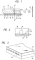
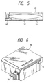
- the ink-jet recording apparatus used in the present invention is not limited to the apparatus as described above in which the head and the ink cartridge are separately provided, and a device can also be preferably used in which these are integrally formed as shown in Fig. 6.
- reference numeral 70 denotes a recording unit, in the interior of which an ink absorber that has held an ink is contained.
- the recording unit is so constructed that the ink in such an ink absorber is ejected in the form of ink droplets from a head 71 having a plurality of orifices.
- a material for the ink absorber it is preferable in the present invention to use polyurethane, cellulose or polyvinyl acetal.
- Reference numeral 72 denotes an air path opening through which the interior of the cartridge is made to communicate with the atmosphere.
- This recording unit 70 can be used in place of the recording head shown in Fig. 4, and is detachably mounted to the carriage 66.
- ink ejecting heads may be arranged in parallel in the direction of movement of the carriage, i.e., the scanning direction on the recording medium, or in vertically in the direction perpendicular thereto.
- nozzles of one head When arranged in vertically, nozzles of one head may be divided into an upper half and a lower half so that the inks and the liquid composition can be fed through separated flow paths.
- the heads may also be so constituted that the order to eject the liquid composition and the inks is in reverse.
- PAA-HCL-3L Polyallylamine hydrochloride (molecular weight: 10,000; available from Nitto Boseki Co., Ltd.)
- PAS-A-5 Polyamine sulfone hydrochloride (molecular weight: 3,500; available from Nitto Boseki Co., Ltd.)
- BTBAC Benzyltributylammonium chloride (available from Tokyo Kasei Co., Ltd.)
- G-50 Benzalkonium chloride (available from Sanyo Chemical Industries, Ltd.)
- SANFLOCK (trade name; available from Sanyo Chemical Industries, Ltd.)
- DEG Diethylene glycol
- SLS-30 Sodium lauryl sulfate (available from Nikko Chemicals Co., Ltd.)
- SSS Sodium stearate (available from Nikko Chemicals Co., Ltd.)
- SUNDET EN Polyoxyethylene lauryl ether sodium sulfate (available from Sanyo Chemical Industries, Ltd.)
- Black solid print samples were formed using the liquid composition and cyan, magenta and yellow inks, and their reflection densities were measured after leaving them for 12 hours, using a reflection densitometer MACBETH RD915 (manufactured by Macbeth Co.). Evaluation was made according to the following criteria.
- Process-black solid print samples were formed using the liquid composition and cyan, magenta and yellow inks. After the samples were formed, the time by which no images became smeared any longer even when the printed areas were rubbed with fingers was measured. Evaluation was made according to the following criteria.
- Samples obtained in the test (1) were left to stand for 30 minutes, and thereafter dipped for 3 seconds in 20°C city water to visually evaluate the retention of prints. Prints with no smearing at all were evaluated as "A”, and those with a level lower than that, as "C”.
- the area on which the liquid composition adhere to the recording medium is the same area as the area on which images are formed with ink, printing duty is 100%, and also the printing direction for the liquid composition and all the inks is one side and the liquid composition is always shot before the inks.
- the ink shot quantities of the three color inks are relatively changed by decreasing the ink shot duty of magenta ink or by increasing the ink ejection quantity of cyan ink or yellow ink or the both of them.
- the ink shot quantities were adjusted by adjusting the widths of pulses the recording heads impart to the heater.
- the process black solid prints showed a high density and also a good color tone.
- the present invention makes it is possible to obtain prints having a good color tone and a high image density at black image portions and having a good character quality level and a perfect water resistance.
Abstract

Description
- This invention relates to an image forming method, and an ink set and an ink-jet machinery that are used therein.
- Ink-jet recording is a process of making a record by causing minute droplets of ink to fly and adhere to a recording medium such as paper. In particular, methods as disclosed in Japanese Patent Publications No. 61-59911, No. 61-59912 and No. 61-59914 in which a heat energy is imparted to ink by using an electrothermal transducer as an ejection energy feeding means, enable easy materialization of higher-density multi-orifice recording head and hence images with a high resolution and a high quality can be recorded at a high speed.
- However, inks conventionally used in ink-jet recording are commonly mainly composed of water and to which water-soluble high-boiling solvents such as glycol are added for the purposes of, e.g., preventing inks from drying and preventing orifices from clogging. When a record is made on plain paper using such ink, no sufficient fixing performance may be attained, or uneven images may occur which are presumed to be due to uneven distribution of fillers and sizing agents on the surface of recording paper. Especially when color images are to be obtained, a plurality of color inks are successively superimposed on paper before they become fixed, and hence colors may blur or unevenly mix at boundaries between images with different color inks (this phenomenon is hereinafter called bleeding) to make it difficult to obtain satisfactory images.
- As a means for improving fixing performance, Japanese Patent Application Laid-open No. 55-65269 discloses adding to ink a compound capable of increasing its permeation. Japanese Patent Application Laid-open No. 55-66976 also discloses use of an ink mainly composed of a volatile solvent. In the former method, although fixing performance and bleeding can be improved and prevented to a certain extent as a result of the increase in ink permeation into recording paper, coloring materials also permeate into the recording paper to a great depth together with ink to cause inconveniences such as a lowering of an image density and chroma and also cause a spread of ink in the lateral direction, which consequently may also cause the problems of a decrease in edge sharpness and a lowering of resolution. As for the latter, in addition to the inconveniences occurring in the former, clogging due to evaporation of solvents undesirably tends to occur at nozzles of the recording head.
- To overcome such problems, methods are also disclosed in which a liquid that enables formation of good images is made to adhere to the recording medium before the ejection of recording ink.
- For example, Japanese Patent Application Laid-open No. 63-299971 discloses a method in which a liquid containing an organic compound having at least two cationic groups per molecule are made to adhere to the recording medium and thereafter the recording is carried out using an ink containing an anionic dye. Japanese Patent Application Laid-open No. 64-9279 also discloses a method in which an acidic liquid containing succinic acid or the like is made to adhere and thereafter the recording is carried out using an ink containing an anionic dye.
- Japanese Patent Application Laid-open No. 64-63185 also discloses a method in which a liquid that can make dyes insoluble is imparted before the ink is imparted to carry out recording.
- All the above methods, however, rely on the deposition of dyes themselves in order to prevent the bleeding of images or improve the water resistance thereof, and have the problems that aggregates of dyes cause a great decrease in coloring properties because of the insolubilization of dyes.
- Especially when black inks which contain a water-soluble black dye are used in such image forming methods, the decrease in coloring properties which is due to agglomeration of dyes causes a phenomenon called bronzing, a phenomenon in which the printed areas that must be originally black colored are reddish to greatly affect the quality of prints.
- The pronzing tends to occur also in the case of process black formed by mixture of yellow, cyan and magenta three colors.
- Accordingly, taking account of the existing circumstances in the prior art techniques, an object of the present invention is to settle the following four technical subjects.
- That is, it is main objects of the present invention, in ink-jet recording carried out on what is called plain paper used as a recording medium;
- (1) to achieve good character quality level while enjoying a good fixing performance;
- (2) to obtain a sufficient image density and make solid prints have a high uniformity;
- (3) to obtain good black-colored prints without causing the bronzing; and
- (4) to perfect the water resistance of recorded images. The above objects of the present invention can be achieved by the invention described below.
- The present invention provides an ink set comprising a combination of a liquid composition containing a cationic substance, with a yellow ink, a cyan ink and a magenta ink, wherein;
the three inks each contain a water-soluble anionic dye and are capable of affording a chromaticity CIE L*a*b* to a black image presented on a recording medium by using these inks in combination within the range of the numerical expressions:
- The present invention also provides an image forming method comprising forming a black portion by using a liquid composition containing a cationic substance, in combination with a yellow ink, a cyan ink and a magenta ink, wherein;
the three inks each contain a water-soluble anionic dye and are capable of affording a chromaticity CIE L*a*b* to a black image presented on a recording medium by using these inks in combination within the range of the numerical expressions:
- The present invention still provides an image forming method comprising imparting a liquid composition, a yellow ink, a cyan ink and a magenta ink by an ink-jet system to record a black portion, wherein the ink set described above is applied.
- The present invention still also provides a recording unit comprising holders for a liquid composition and an ink and a head for ejecting the liquid composition and the ink in the form of droplets, wherein the ink set described above is applied.
- The present invention further provides an ink cartridge comprising holders for a liquid composition and an ink, wherein the ink set described above is applied.
- The present invention still further provides an ink-jet recording apparatus comprising the recording unit described above.
- The present invention still further provides an ink-jet recording apparatus comprising the ink cartridge described above.
- The present invention still further provides an image which is presented using a liquid composition containing a cationic substance, in combination with a yellow ink, a cyan ink and a magenta ink, and contains a black portion having on a recording medium a chromaticity CIE L*a*b* within the range of the numerical expressions:

- Fig. 1 illustrates a longitudinal cross section of a head assembly of an ink-jet recording apparatus.
- Fig. 2 is a transverse cross section of the head assembly of an ink-jet recording apparatus.
- Fig. 3 is a perspective illustration of the appearance of another head assembly of an ink-jet recording apparatus.
- Fig. 4 is a perspective illustration of an example of an ink-jet recording apparatus.
- Fig. 5 is a vertical cross-sectional illustration of an ink cartridge.
- Fig. 6 is a perspective illustration of a recording unit.
- How the present invention operates will be described below.
- In the present invention, the liquid composition and inks mentioned above are mixed at the part where they have permeated into a recording paper. As a result, the cationic substance and the anionic groups contained in the inks electrostatically combine to cause instantaneous aggregation, and the dye components and solvent components in the inks become separate (hereinafter this phenomenon is called solid-liquid separation), so that only the solvent components permeate into the recording paper and hence the coloring material, dye components, cause no bleeding.
- The solid-liquid separation explained above more efficiently takes place when the liquid composition contains as the cationic substance a component with a molecular weight of 1,000 or less and a component with a molecular weight of 1,500 or more. The molecular weight referred to in the present invention means a number average molecular weight, which is measured by methods such as GPC (gel permeation chromatography).
- The detailed mechanism is unclear as to the reason why the solid-liquid separation more efficiently takes place when the two kinds of cationic substances are present in the liquid composition. Stated generally, it can be explained as follows.
- First, as the first stage of the reaction, the low-molecular weight component of the cationic substance contained in the liquid composition and the water-soluble dye having anionic groups used in the ink ionically act on each other to cause association, which causes instantaneous separation from the liquid phase.
- Next, as the second stage of the reaction, the product of the above association between the dye and the low-molecular weight cationic substances is adsorbed by the high-molecular weight component and hence the size of dye aggregates produced upon the association further increases, so that they become difficult to enter into the gaps between fibers of the recording paper. As the result, only the liquid having undergone solid-liquid separation permeates into the recording paper and hence both the character quality level and the fixing performance can be achieved.
- At the same time, the aggregates formed of the low-molecular weight component, the anionic dye and the cationic substance, produced by the mechanism as explained above, come to have a large viscosity and do not move with the movement of the liquid medium. Hence, no edge sharpness of characters or images is damaged even when the fixing is accelerated as in the prior art, and a good character quality level can be obtained. The above aggregates are also substantially water-insoluble and hence the water resistance of the images formed becomes perfect.
- In the present invention, it is presumed that the aggregates may cause crystallization on the recording paper, where, especially when the ink is black, the prints may have a reddish color tone and can not become black depending on differences in the concentration of dyes in the ink, the type of dyes, the quantity of ink ejection and the type of paper. This phenomenon has been similarly questioned also in the case of process black formed by mixture of yellow, cyan and magenta three colors.
- Now, when black images are formed by mixture of yellow, cyan and magenta three colors, the present inventors have employed the means shown below in three points.
- (1) The combination of water-soluble anionic dyes used in the yellow, cyan and magenta inks is optimized.
- (2) The proportion of ink shot for the yellow, cyan and magenta inks is controlled when black images are formed.
- (3) An anionic surface active agent or anionic high-molecular weight substance is added to at least one of the yellow, cyan and magenta inks.
- As the result, they have found that good black images having on the recording medium a chromaticity CIE L*a*b* within the range of the numerical expressions:

- The present invention will be described below in greater detail by giving preferred embodiments of the present invention.
- The essential component to be contained in the liquid composition referred to in the present invention is the cationic substance. The function of the cationic substance in the present invention is to electrostatically combine with the water-soluble anionic dye contained in ink, described later, to form aggregates. As a more preferred embodiment in the working of the present invention, the cationic substance comprises the following two components as mentioned above.
- (1) A low-molecular weight cationic substance with a molecular weight of 1,000 or less.
- (2) A high-molecular weight cationic substance with a molecular weight of from 1,500 to 10,000.
The essential component that constitutes the inks described in the present invention is; - (3) a water-soluble anionic dye having one or more anionic groups.
- Specific examples of the component (1) low-molecular weight cationic substance with a molecular weight of 1,000 or less are shown below.
- Primary, secondary and tertiary amine salt compounds, specifically including hydrochlorides or acetates of lauryl amine, coconut amine, stearyl amine and rosin amine; quaternary ammonium salt compounds specifically including lauryltrimethylammonium chloride, lauryldimethylbenzylammonium chloride, benzyltributylammonium chloride and benzalkonium chloride; pyridinium salt compounds specifically including cetylpyridinium chloride and cetylpyridinium bromide; imidazoline type cationic compounds specifically including
2-butadecenyl-hydroxyethylimidazoline; and ethylene oxide addition products of higher alkylamines, specifically including hydroxyethylstearylamine. In the present invention, amphoteric surface active agents having cationic properties in a certain pH range can also be used. They may more specifically including amino acid type amphoteric surface active agents, and carboxylate type amphoteric surface active agents such as R-NH-CH₂-CH₂-COOH type compounds and betaine type compounds, specifically including
stearyldimethylbetaine and lauryldihydroxyethylbetaine, as well as sulfuric ester type, sulfonic acid type and phosphoric ester type amphoteric surface active agents. Of course, when these amphoteric surface active agents are used, the liquid composition must be prepared so as to have a pH not higher than their isoelectric points, or must be adjusted so as to have a pH not higher than the isoelectric points upon its mixture with inks on the recording medium, either means of which may be taken. - The low-molecular weight cationic compounds are as exemplified above. Needless to say, the compounds that can be used in the present invention are by no means limited to these.
- As other examples of the component (1), monomers or oligomers of the cationic high-molecular weight component described later may also be used.
- Examples of the low-molecular weight cationic substance with a molecular weight of 1,000 or less are as shown above. In the present invention, those having a molecular weight ranging from 100 to 700 are particularly preferred in view of the advantages that they have surface activities, cause rapid reaction with dyes and contribute an improvement in edge sharpness of images.
- The component (2) high-molecular weight substance with a molecular weight of from 1,500 to 10,000 also has the operation and effect in the present invention as described above, i.e., as the second stage of the reaction of inks with the liquid composition, it adsorbs in its molecule the product of the association between the dye and the low-molecular weight components of the cationic substances to further increase the size of dye aggregates produced upon the association, and to make them difficult to enter into the gaps between fibers of the recording paper, so that only the liquid having undergone solid-liquid separation permeates into the recording paper and hence both the character quality level and the fixing performance can be achieved. Such a cationic high-molecular weight substance may include, for example, polyallylamine hydrochloride, polyamine sulfone hydrochloride, polyvinylamine hydrochloride, and chitosan acetate. Of course, examples are by no means limited to these. Examples are also by no means limited to hydrochloride types and acetate types.
- As other examples, compounds obtained by partly cationizing nonionic high-molecular weight substances may also be used.
- They may specifically include copolymers of vinyl pyrrolidone with aminoalkylalkylate quaternary salts and copolymers of acrylamide with aminomethyl acrylamide quaternary salts. Needless to say, examples are by no means limited to these.
- The high-molecular weight substances and cationic high-molecular weight substance described above are satisfactory if they are water-soluble, and may also be in the form of dispersions such as latexes and emulsions.
- These cationic high-molecular weight substances may have a molecular weight of from 1,500 to 10,000, and such compounds are preferred in view of the working of the present invention. They may more preferably be compounds having a molecular weight of from 1,500 to 7,000, which are more preferred in view of the advantage that they cause no lowering of coloring properties of dyes. They also have the advantage that the ejection performance of the liquid composition can be well maintained because, when the liquid composition is applied to a recording medium by means of an ink-jet recording head, a compound having a molecular weight on the lower molecular weight side can maintain a lower solution viscosity even when used in a larger content.
- The molecular weight referred to in the above is meant to be a molecular weight in terms of polyethylene oxide, which is measured by analytical methods as exemplified by GPC (gel permeation chromatography).
- These components contained in the liquid composition may preferably be in an amount ranging from 0.05 to 20% by weight on the basis of weight. An optimum rage must be determined according to the combination of the respective substances used.
- Other components that constitute the liquid composition will be specifically described below. In addition to the components (1) and (2) described above, the liquid composition may usually comprise water, a water-soluble organic solvent and other additives.
- The water-soluble organic solvent may include amides such as dimethylformamide and dimethylacetamide; ketones such as acetone; ethers such as tetrahydrofuran and dioxane; polyalkylene glycols such as polyethylene glycol and polypropylene glycol; alkylene glycols such as ethylene glycol, propylene glycol, butylene glycol, triethylene glycol, hexylene glycol and diethylene glycol; 1,2,6-hexanetriol, thiodiglycol; lower alkyl ethers of polyhydric alcohols, such as ethylene glycol methyl ether, diethylene glycol monomethyl ether and triethylene glycol monomethyl ether; and monohydric alcohols such as ethanol, isopropyl alcohol, n-butyl alcohol and isobutyl alcohol; as well as glycerol, N-methyl-2-pyrrolidone, 1,3-dimethyl-2-imidazolidinone, triethanolamine, sulforane, and dimethylsulfoxide; any of which may be used. There are no particular limitations on the content of the water-soluble organic solvent, which may preferably be in the range of from 1 to 60% by weight, and more preferably from 5 to 30% by weight. If necessary, additives such as a viscosity modifier, a pH adjuster, an anticeptic, a surface active agent, an antioxidant and an evaporation accelerator may also be added. The selection of surface active agents is especially important in order to adjust the permeation of liquid.
- The liquid composition as described in the present invention can be used so long as it has such a color tone that may cause no change in the color tone of recording ink. As its physical properties, it may preferably have a pH ranging from 3 to 12, a surface tension of from 10 to 60 dyne/cm and a viscosity ranging from 1 to 30 cP, at around 25°C.
- Recording inks used in the present invention will be described below.
- The recording inks used in the present invention each comprise the water-soluble anionic dye having one or more anionic groups as described above, water, a water-soluble organic solvent and other components as exemplified by a viscosity modifier, a pH adjuster, an anticeptic, a surface active agent, an antioxidant and so forth.
- The water-soluble anionic dye having one or more anionic groups, used in the present invention, may be any of the water-soluble acid dyes, direct dyes and reactive dyes listed in COLOR INDEX, without any particular limitations. Those not listed in COLOR INDEX may also be used without any particular limitations so long as they have one or more anionic groups, e.g., a sulfonic group or a carboxyl group. The water-soluble anionic dye herein referred to also includes of course those having a dependence of solubility on pH.
- Water-soluble cyan dyes having one or more anionic groups, used in the present invention, may be any of the water-soluble acid dyes, direct dyes and reactive dyes listed in COLOR INDEX, without any particular limitations.
- For example, C.I.
Acid Blue Reactive Blue - Those not listed in COLOR INDEX may also be used without any particular problems so long as they have an anionic group, e.g., a sulfonic group or a carboxyl group.
- In respect of yellow dyes, similar to cyan dyes any water-soluble anionic dyes having one or more anionic groups can be used without any particular problems.
- They can be specifically exemplified by C.I. Direct Yellow 86, 142 and 144, C.I.
Acid Yellow - In respect of magenta dyes, similarly any water-soluble anionic dyes having one or more anionic groups can be used without any particular problems.
- They can be specifically the water-soluble acid dyes, direct dyes and reactive dyes listed in COLOR INDEX, as exemplified by C.I.
Acid Red 6, 8, 35, 37, 52, 92, 133 and 289 and so forth, and also a dye represented by the formula
wherein R₁, R₂ and R₃ each represent a functional group shown below.
R₁ and R₂: H, CH₃, OCH₃, -SO₃M or -COOM.
R₃: -COCH₃,
wherein R₄ and R₅ each represent -COOM, R₆ or -OR₆, where R₆ represents a C₂ to C₆ alkyl chain which may be branched; and M represents sodium, lithium, an organic amine or ammonium. - There are no particular limitations on the content of the dye in the ink of the present invention, which may usually be from 0.1 to 15% by weight, preferably from 0.5 to 10% by weight, and more preferably from 0.5 to 6% by weight, based on the total weight of the ink. The dye may be used alone or in combination.
- The medium suitable for use in the inks of the present invention is water or a mixed solvent of water and a water-soluble organic solvent. As the water, it is preferable to use not usual city water containing various ions but deionized water.
- The water-soluble organic solvent used by mixture with water may include, for example, alkyl alcohols having 1 to 5 carbon atoms such as methyl alcohol, ethyl alcohol, n-propyl alcohol, isopropyl alcohol, n-butyl alcohol, sec-butyl alcohol, tert-butyl alcohol, isobutyl alcohol and n-pentanol; amides such as dimethylformamide and dimethylacetamide; ketones or ketoalcohols such as acetone and diacetone alcohol; ethers such as dioxane; polyalkylene glycols such as polyethylene glycol and polypropylene glycol; alkylene glycols the alkylene group of which has 2 to 6 carbon atoms, such as ethylene glycol, propylene glycol, butylene glycol, triethylene glycol, hexylene glycol and diethylene glycol; 1,2,6-hexanetriol, thiodiglycol; glycerol; lower alkyl ethers of polyhydric alcohols, such as ethylene glycol monomethyl ether, ethylene glycol monoethyl ether, diethylene glycol monomethyl ether, diethylene glycol monoethyl ether, triethylene glycol monomethyl ether and triethylene glycol monoethyl ether; lower dialkyl ethers of polyhydric alcohols, such as triethylene glycol dimethyl ether, triethylene glycol diethyl ether, tetraethylene glycol dimethyl ether, tetraethylene glycol dimethyl ether and tetraethylene glycol diethyl ether; sulforane, N-methyl-2-pyrrolidone, and 1,3-dimethyl-2-imidazolidinone.
- The solvents in the inks of the present invention are used under selection of suitable ones from the above organic solvents. In the case of the inks of the present invention, diethylene glycol or thiodiglycol is preferred from the viewpoint of the prevention of clogging of nozzles with inks.
- From the viewpoint of frequency response, use of lower alcohols or surface active agents is preferred.
- Thus, as solvent composition preferable in the inks of the present invention, the solvent may comprise, in addition to the water, the various components as described above.
- In the inks of the present invention, the water-soluble organic solvent in each ink may be usually in a content of from 2 to 80% by weight, preferably from 3 to 70% by weight, and more preferably from 4 to 60% by weight, based on the total weight of the ink.
- In the inks of the present invention, the water in each ink may be usually in a content of from 10 to 97.5% by weight, preferably from 35 to 97.5% by weight, and more preferably from 45 to 97.5% by weight, based on the total weight of the ink. If the amount of water in the ink is less than 10% by weight, a low-volatile organic solvent may remain in a large quantity in the recorded images formed, to give a possibility of causing the problems of migration of dyes and bleeding of images.
- The inks of the present invention may optionally contain, in addition to the components described above, pH adjusters, viscosity modifiers, surface tension modifiers. The pH adjusters may include various organic amines such as diethanolamine and triethanolamine, and inorganic alkali agents formed of alkali metal hydroxides such as sodium hydroxide, lithium hydroxide and potassium hydroxide.
- The inks of the present invention may have a viscosity of from 1 to 20 cP, and preferably from 1 to 15 cP, a surface tension of 15 dyne/cm or above, and preferably 25 dyne/cm or above, and a pH of about 6 to 10, at 25°C, respectively.
- In order to more effectively carry out the present invention, anionic surface active agents or anionic high-molecular weight substances may be added to the inks in addition to the components described above. The amphoteric surface active agents previously described may also be used, adjusting the pH so as to be higher than their isoelectric points. Examples of such anionic surface active agents are commonly available carboxylate type, sulfuric ester type, sulfonic acid type and phosphoric ester type ones, any of which can be used without problems.
- Examples of the anionic high-molecular weight substances are alkali-soluble type resins, specifically including sodium polyacrylate or those obtained by copolymerizing acrylic acid on part of high molecules. Of course, examples are not limited to these.
- There are no particular limitations on the recording medium used when the present invention is carried out. What is called plain paper such as copy paper and bond paper conventionally used can be preferably used. Of course, coated papers specially prepared for ink-jet recording or OHP transparent films can also be preferably used. Usual woodfree paper and glossy paper can also preferably be used.
- In a preferred embodiment of the image forming method of the present invention, the liquid composition described above is adhered to an image forming area, or an image forming area and in the vicinity thereof, of the recording medium prior to an ink, and thereafter the ink is adhered to that area. Herein the image forming area is meant to be the area to which ink dots adhere, and the vicinity of the image forming area is meant to be the area distant by 1 dot to 5 dots from the periphery of the area to which ink dots adhere.
- As methods to adhere the liquid composition to the recording medium, one may contemplate spraying or use of a roller, by which the liquid composition is made to adhere to the whole surface of the recording medium. However, ink-jet systems are preferred which can adhere ink uniformly to only an image forming area to which the ink should adhere and in the vicinity of the image forming area. There are no particular limitations on the time after the liquid composition has been adhered to the recording medium and before the ink is adhered thereto.
- As stated above, various ink-jet systems may be used as methods to adhere the liquid composition and the ink to the recording medium. It is particularly preferable to use a system of ejecting ink droplets by the aid of bubbles produced by heat energy.
- How to form the black image by mixture of yellow ink, cyan ink and magenta ink (hereinafter "process black") will be described below.
- In the present invention, a preferred means for bringing the chromaticity CIE L*a*b* of the process black on the recording medium into the range of 10 ≦ L* ≦ 30, 0 ≦ a* ≦ 7 and -10 ≦ b* ≦ 0 is exemplified by the following three points.
- (1) The combination of water-soluble anionic dyes used in the yellow, cyan and magenta inks is optimized.
- (2) The proportion of ink shot for the yellow, cyan and magenta inks is controlled when black images are formed.
- (3) The anionic surface active agent or anionic high-molecular weight substance is added to at least one of the yellow, cyan and magenta inks.
- Operation for the three points as stated above makes it possible to prevent the bronzing that is questioned in the process black formed by mixture of yellow, cyan and magenta inks and to obtain a good black images having on the recording medium a chromaticity CIE L*a*b* within the above ranges.
- With regard to the above item (2), the following two methods can be employed.
- (2-a) In forming a black image, the ink shot duty of magenta ink is controlled to be 50 to 80% of the ink shot duties of other two color inks.
- (2-b) In forming a black image, the quantity of yellow ink and cyan ink each to be imparted to the recording medium is increased by 10 to 50% with respect to that of magenta ink.
- As methods for relatively increasing the amount of inks to be imparted can be exemplified by methods of, e.g., raising temperature-conditioning temperature of the recording head, and increasing the energy applied to the head by changing pulse width, voltage and so forth.
- An example of the ink-jet recording apparatus preferable in the ink-jet recording carried out using the inks of the present invention will be described below. Figs. 1, 2 and 3 show examples of the construction of the recording head, which is a main component of the apparatus.
- A
head 13 is formed by bonding a glass, ceramic or plastic plate or the like provided with anink flow path 14, to aheating head 15 used in thermal recording (the drawing shows a head, to which, however, is not limited). Theheating head 15 is comprised of aprotective film 16 formed of silicon oxide or the like, aluminum electrodes 17-1 and 17-2, aheating resistor layer 18 formed of nichrome or the like, aheat accumulating layer 19, and asubstrate 20 with good heat dissipation properties, made of alumina or the like. - The
ink 21 stands reached an ejection orifice (minute opening) 22 and ameniscus 23 is formed there by a pressure P. - Now, upon application of electric signals to the electrodes 17-1 and 17-2, heat is abruptly generated at the region denoted by n in the
thermal head 15, so that bubbles are generated in theink 21 coming into contact with this region. The pressure thus produced thrusts out themeniscus 23 and theink 21 is ejected from theorifice 22 in the form of recording minute drops 24 to fly against arecording medium 25. Fig. 3 schematically illustrates a multi-head comprising the head as shown in Fig. 1 arranged in a large number. This multi-head is prepared by closely bonding aglass plate 27 havingmultiple grooves 26, to aheating head 28 similar to the head as illustrated in Fig. 1. - Fig. 1 is a cross-sectional view of the
head 13 along its ink flow path, and Fig. 2 is a cross-sectional view along the line 2-2 in Fig. 1. - Fig. 4 shows an example of the ink-jet recording apparatus in which such a head has been incorporated.
In Fig. 4,reference numeral 61 denotes a blade serving as a wiping member in the form of a cantilever, one end of which is a stationary end retained by a blade-retaining member. Theblade 61 is provided at the position adjacent to the region in which a recording head makes a record. In the present example, the blade is retained in such a form that it projects to the course through which the recording head is moved.Reference numeral 62 denotes a cap, which is provided at the home position adjacent to theblade 61, and is so constituted that it moves in the direction perpendicular to the direction in which the recording head is moved and comes into contact with the face of ejection openings to carry out capping.Reference numeral 63 denotes an ink absorber provided adjoiningly to theblade 61, and, similar to theblade 61, is retained in such a form that it projects to the course through which the recording head is moved. - The
above blade 61,cap 62 andabsorber 63 constitute anejection restoration assembly 64, where theblade 61 and theabsorber 63 remove the water, dust or the like from the ink ejection opening face. -
Reference numeral 65 denotes the recording head having an ejection energy generating means and ejects ink to the recording medium set opposingly to the ejection opening face provided with ejection openings, to carry out recording.Reference numeral 66 denotes a carriage on which therecording head 65 is mounted so that therecording head 65 can be moved. Thecarriage 66 is slidably associated with aguide shaft 67. Part of thecarriage 66 is connected (not shown) with abelt 69 driven by amotor 68. Thus, thecarriage 66 can be moved along theguide 67 and hence therecording head 65 can be moved from a recording region to a region adjacent thereto. -
Reference numeral 51 denotes a paper feeding part from which recording mediums are inserted, and 52, a paper feed roller driven by a motor (not shown). With such construction, the recording medium is fed to the position opposing to the ejection opening face of the recording head, and, with progress of recording, outputted from a paper output section provided with apaper output roller 53. - In the above constitution, the
cap 62 of thehead restoration assembly 64 is receded from the moving course of therecording head 65 when therecording head 65 is returned to its home position, e.g., after completion of recording, and theblade 61 stands projected to the moving course. As a result, the ejection opening face of therecording head 65 is wiped. When thecap 62 comes into contact with the ejection opening face of therecording head 65 to carry out capping, thecap 62 is moved in such a way that it projects to the moving course of the recording head. - When the
recording head 65 is moved from its home position to the position at which recording is started, thecap 62 and theblade 61 are at the same position as the position where the ejection opening face is wiped. As a result, the ejection opening face of therecording head 65 is wiped also at the time of this movement. - The above movement of the recording head to its home position is made not only at the time of the completion of recording or restoration of ejection, but also when the recording head is moved between recording regions for the purpose of recording, during which it is moved to the home position adjacent to each recording region at given intervals, where the ejection opening face is wiped in accordance with this movement.
- Fig. 5 shows an example of an ink cartridge, denoted as 45, that has held the ink being fed to the head through an ink-feeding tube. Herein
reference numeral 40 denotes an ink holder, e.g., an ink bag, that has held the feeding ink. The top thereof is provided with astopper 42 made of rubber. A needle (not shown) may be inserted to thisstopper 42 so that the ink in theink holder 40 can be fed to the head.Reference numeral 44 denotes an absorber that receives a waste ink. In the present invention, it is preferable for the ink holder to be formed of a polyolefin, especially polyethylene, at its face coming into contact with ink. The ink-jet recording apparatus used in the present invention is not limited to the apparatus as described above in which the head and the ink cartridge are separately provided, and a device can also be preferably used in which these are integrally formed as shown in Fig. 6. - In Fig. 6,
reference numeral 70 denotes a recording unit, in the interior of which an ink absorber that has held an ink is contained. The recording unit is so constructed that the ink in such an ink absorber is ejected in the form of ink droplets from a head 71 having a plurality of orifices. As a material for the ink absorber, it is preferable in the present invention to use polyurethane, cellulose or polyvinyl acetal.Reference numeral 72 denotes an air path opening through which the interior of the cartridge is made to communicate with the atmosphere. Thisrecording unit 70 can be used in place of the recording head shown in Fig. 4, and is detachably mounted to thecarriage 66. - To constitute the head in the working of the present invention, when the system in which the liquid composition is ejected by the ink-jet head, ink ejecting heads may be arranged in parallel in the direction of movement of the carriage, i.e., the scanning direction on the recording medium, or in vertically in the direction perpendicular thereto. When arranged in vertically, nozzles of one head may be divided into an upper half and a lower half so that the inks and the liquid composition can be fed through separated flow paths. Of course, the heads may also be so constituted that the order to eject the liquid composition and the inks is in reverse.
- The present invention invention will be described below in greater detail by giving Examples and Comparative Examples.
- The components as shown in Table 1 were mixed and dissolved, followed by filtration under pressure using a membrane filter (trade name: FLUOROPORE FILTER; available from Sumitomo Electric Industries, Ltd.) with a pore size of 0.22 µm to obtain liquid compositions M-1 to M-4.
Table 1 Cationic low-molecular compound Cationic high-molecular compound Organic solvent Water M-1 None PAA-HCL-3L (3*) DEG (10*) 87* M-2 BTBAC (3*) PAA-HCL-3L (3*) DEG (10*) 84* M-3 G-50 (2*) PAS-A-5 (5*) DEG (10*) 83* M-4 G-50 (2*) SANFLOCK 700(5*) DEG (10*) 83* * parts by weight - In the table, abbreviations or trade names stand for the compounds shown below. PAA-HCL-3L: Polyallylamine hydrochloride
(molecular weight: 10,000; available from Nitto Boseki Co., Ltd.)
PAS-A-5: Polyamine sulfone hydrochloride
(molecular weight: 3,500; available from Nitto Boseki Co., Ltd.)
BTBAC: Benzyltributylammonium chloride
(available from Tokyo Kasei Co., Ltd.)
G-50: Benzalkonium chloride
(available from Sanyo Chemical Industries, Ltd.)
SANFLOCK:
(trade name; available from Sanyo Chemical Industries, Ltd.)
DEG: Diethylene glycol
Next, the colorant components of inks and anionic surface active agent as shown in Table 2, DEG (10 parts by weight) and water (the balance up to 100 parts) were mixed, followed by filtration under pressure using a membrane filter (trade name: FLUOROPORE FILTER; available from Sumitomo Electric Industries, Ltd.) with a pore size of 0.22 µm to obtain ink combinations I-1 to I-5.Table 2 Yellow dye (Anionic surfactant) Magenta dye (Anionic surfactant) Magenta dye (Anionic surfactant) I-1 AY-23 (1.5*) AR-52 (2.5*) DBL-199 (3.0*) I-2 DY-142 (1.5*) AR-289 (2.5*) DBL-199 (2.8*) AB-9 (0.7*) I-3 AY-23 (1.5*) AR-52 (2.5*) DBL-199 (3.0*) (SLS-30)(1.0*) I-4 DY-86 (2.5*) (SSS) (0.5*) AR-133 (2.5*) DBL-199 (3.0*) (SSS) (0.5*) I-5 DY-86 (2.5*) (SUNDET EN) (1.0*) AR-92 (2.5*) (SUNDET EN) (1.0*) DBL-199 (3.0*) (SUNDET EN) (1.0*) * parts by weight - In the table, abbreviations or trade names stand for the compounds shown below. SLS-30: Sodium lauryl sulfate
(available from Nikko Chemicals Co., Ltd.)
SSS: Sodium stearate
(available from Nikko Chemicals Co., Ltd.) SUNDET EN: Polyoxyethylene lauryl ether sodium sulfate
(available from Sanyo Chemical Industries, Ltd.) - AY:
- C.I. Acid Yellow
- AR:
- C.I. Acid Red
- DY:
- C.I. Direct Yellow
- DBL:
- C.I. Direct Blue
- AB:
- C.I. Acid Blue
- Next, using the liquid composition and inks obtained in the above manner, records were made on commercially available copy paper. As an ink-jet recording apparatus used, the same recording apparatus as shown in Fig. 4 was used, and its head was so constructed that heads for ejecting inks and liquid compositions were arranged in parallel in the direction of movement of the carriage and the inks are always shot later for recording. The recording heads used here had a recording density of 360 dpi and were driven under conditions of a drive frequency of 5 kHz. Their ejection volume per dot was 55 pl. These recording conditions were constant throughout Examples of the present invention and Comparative Example. Printing tests were made under uniform environmental conditions of 25°C/55%RH.
- Recorded images were evaluated in the following way.
- Black solid print samples were formed using the liquid composition and cyan, magenta and yellow inks, and their reflection densities were measured after leaving them for 12 hours, using a reflection densitometer MACBETH RD915 (manufactured by Macbeth Co.). Evaluation was made according to the following criteria.
- AA:
- Reflection density is 1.25 or higher.
- A:
- Reflection density is from 1.20 to 1.24.
- B:
- Reflection density is from 1.10 to 1.19.
- C:
- Reflection density is 1.09 or lower.
- Process-black solid print samples were formed using the liquid composition and cyan, magenta and yellow inks. After the samples were formed, the time by which no images became smeared any longer even when the printed areas were rubbed with fingers was measured. Evaluation was made according to the following criteria.
- AA:
- Fixed in 10 seconds.
- A:
- Fixed in from 11 to 20 seconds.
- B:
- Fixed in from 21 to 30 seconds.
- C:
- Fixed after 30 seconds.
- Alphanumerics in the above process black were printed, and the prints were visually evaluated. Those with no conspicuous feathering were evaluated as "A", and those with a level lower than that, as "C".
- Samples obtained in the test (1) were left to stand for 30 minutes, and thereafter dipped for 3 seconds in 20°C city water to visually evaluate the retention of prints. Prints with no smearing at all were evaluated as "A", and those with a level lower than that, as "C".
- Solid print samples in the above process black were formed to make visual evaluation. Prints with a good tone as black color was evaluated as "A", and those with reddish tone, as "C".
- Throughout Examples of the present invention and Comparative Example, the area on which the liquid composition adhere to the recording medium is the same area as the area on which images are formed with ink, printing duty is 100%, and also the printing direction for the liquid composition and all the inks is one side and the liquid composition is always shot before the inks.
- In Examples, the ink shot quantities of the three color inks are relatively changed by decreasing the ink shot duty of magenta ink or by increasing the ink ejection quantity of cyan ink or yellow ink or the both of them. The ink shot quantities were adjusted by adjusting the widths of pulses the recording heads impart to the heater.
- Combinations of the liquid composition and inks as used in Examples are shown in Tables 3 and 4. Results of the evaluation on items (1) to (5) are also shown together in Tables 3 and 4.
Table 3 I- M- Ink shot mode (1) (2) (3) (4) (5) CIE L*a*b* Example: L* a* b* 1 1 1 (B) A A A A A 28, 5.1, -4.5 2 1 2 (B) AA AA A A A 26, 4.8, -5.0 3 1 3 (B) AA AA A A A 25, 4.6, -4.7 4 1 4 (B) AA AA A A A 26, 4.5, -4.8 5 2 1 (C) A A A A A 25, 5.0, -7.9 6 2 2 (C) AA AA A A A 25, 4.8, -8.0 7 2 3 (C) AA AA A A A 24, 4.7, -8.1 8 2 4 (C) AA AA A A A 24, 4.7, -7.9 9 3 1 (A) A A A A A 25, 4.8, -6.0 10 3 2 (A) AA AA A A A 23, 4.7, -5.8 11 3 3 (A) AA AA A A A 24, 4.8, -5.5 12 3 4 (A) AA AA A A A 23, 5.0, -5.9 Table 4 I- M- Ink shot mode (1) (2) (3) (4) (5) CIE L*a*b* Example: L* a* b* 13 4 1 (A) A A A A A 27, 4.3, -4.0 14 4 2 (A) AA AA A A A 25, 4.9, -4.5 15 4 3 (A) AA AA A A A 25, 4.5, -4.1 16 4 4 (A) AA AA A A A 25, 4.6, -4.3 17 4 1 (C) A A A A A 25, 5.0, -8.9 18 4 2 (C) AA AA A A A 23, 5.1, -8.0 19 4 3 (C) AA AA A A A 23, 5.2, -8.5 20 4 4 (C) AA AA A A A 23, 4.8, -8.2 21 5 1 (A) A A A A A 26, 5.0, -5.0 22 5 2 (A) AA AA A A A 25, 4.9, -5.5 23 5 3 (A) AA AA A A A 23, 4.8, -5.1 24 5 4 (A) AA AA A A A 23, 5.0, -5.2 - The symbols for the ink shot mode as used in Tables 3 and 4 indicate the following.
- (A): Process black prints are formed at each 100% duty for the three inks, yellow ink, cyan ink and magenta ink.
- (B): When process black prints are formed, the magenta ink shot duty is controlled to be 70% of the ink shot duties of other two color inks.
- (C): The quantity of yellow ink and magenta ink each ejected when process black prints are formed is increased by 20% with respect to that of magenta ink.
- In the above Examples, the process black solid prints showed a high density and also a good color tone.
- Printing tests were carried out in the same manner as in Examples except that the ink composition I-5 was used and no liquid composition was used, and evaluation was made in entirely the same manner as in Examples. The results obtained are shown below.
Table 5 I- Ink shot mode (1) (2) (3) (4) (5) CIE L*a*b* Comparative Example: L* a* b* 1 5 (A) B C A C C 28, 10, 0.5 - In the above Comparative Example, prints samples showed a low density, and the process black solid print samples were reddish undesirably.
- As described above, the present invention makes it is possible to obtain prints having a good color tone and a high image density at black image portions and having a good character quality level and a perfect water resistance.
Claims (34)
- An ink set comprising a combination of a liquid composition containing a cationic substance, with a yellow ink, a cyan ink and a magenta ink, wherein;
said three inks each contain a water-soluble anionic dye and are capable of affording a chromaticity CIE L*a*b* to a black image presented on a recording medium by using these inks in combination within the range of the numerical expressions;
- The ink set according to claim 1, wherein said anionic dye is any one of acid dye, a direct dye and a reactive dye.
- The ink set according to claim 1, wherein said anionic dye is contained in each of said inks in an amount of from 0.1% by weight to 15% by weight based on the total weight of the ink.
- The ink set according to claim 1, wherein said liquid composition comprises a low-molecular weight cationic substance and a high-molecular weight cationic substance in combination.
- The ink set according to claim 1, wherein said liquid composition comprises a cationic substance with a molecular weight of 1,000 or less and a cationic substance with a molecular weight of 1,500 or more in combination.
- The ink set according to claim 4, wherein said low-molecular weight cationic substance has a molecular weight ranging from 100 to 700.
- The ink set according to claim 4, wherein said high-molecular weight cationic substance has a molecular weight ranging from 1,500 to 10,000.
- The ink set according to claim 1, wherein said each ink further contains water and a water-soluble organic solvent.
- The ink set according to claim 1, wherein said liquid composition further contains water and a water-soluble organic solvent.
- The ink set according to claim 1, wherein said each ink contains water in an amount ranging from 10% by weight to 97.5% by weight based on the total weight of the ink.
- The ink set according to claim 1, wherein said each ink contains a water-soluble organic solvent in an amount ranging from 2% by weight to 80% by weight based on the total weight of the ink.
- The ink set according to claim 1, wherein said each ink has a viscosity at 25°C in the range of from 1 cP to 20 cP.
- The ink set according to claim 1, wherein said each ink has a surface tension of 30 dyne/cm or above.
- The ink set according to claim 1, wherein said each ink has a pH value ranging from 6 to 10.
- The ink set according to claim 1, wherein said yellow ink or cyan ink contains an anionic substance other than the dye in the range of from 0.05% by weight to 10% by weight.
- The ink set according to claim 15, wherein said anionic substance is a surface active agent.
- The ink set according to claim 1, wherein said magenta ink contains a dye represented by the formula:

R₃ is -COCH₃,
- An image forming method comprising forming a black portion by using a liquid composition containing a cationic substance, in combination with a yellow ink, a cyan ink and a magenta ink, wherein;
said three inks each contain a water-soluble anionic dye and are capable of affording a chromaticity CIE L*a*b* to a black image presented on a recording medium by using these inks in combination within the range of the numerical expressions:
- An image forming method comprising imparting a liquid composition, a yellow ink, a cyan ink and a magenta ink by an ink-jet system to record a black portion, wherein the ink set according to any one of claims 1 to 17 is applied.
- The image forming method according to claim 19, wherein said ink-jet system is a system comprising applying a heat energy to the ink to generate ink droplets.
- The image forming method according to claim 19, wherein said yellow ink and cyan ink are each imparted to the recording medium in a quantity larger by 10% to 50% with respect to that of said magenta ink.
- The image forming method according to claim 19, wherein the ink shot duty of said magenta ink is controlled within the range of from 50% to 80% of that of said yellow ink and cyan ink each.
- A recording unit comprising holders for a liquid composition and an ink and a head that ejects the liquid composition and the ink in the form of droplets, wherein the ink set according to any one of claims 1 to 17 is applied.
- The recording unit according to claim 23, wherein an ink-jet system that generates ink droplets by the action of a heat energy is applied to said head.
- An ink cartridge comprising holders for a liquid composition and an ink, wherein the ink set according to any one of claims 1 to 17 is applied.
- An ink-jet recording apparatus comprising the recording unit according to claim 23 or 24.
- An ink-jet recording apparatus comprising the ink cartridge according to claim 25.
- The ink-jet recording apparatus according to claim 25, having a head for generating ink droplets by an ink-jet system.
- An ink-jet recording apparatus comprising the ink set according to any one of claims 1 to 17.
- The ink-jet recording apparatus according to claim 29, further having a head for generating ink droplets by an ink-jet system.
- An image which is presented using a liquid composition containing a cationic substance, in combination with a yellow ink, a cyan ink and a magenta ink, and contains a black portion having on a recording medium a chromaticity CIE L*a*b* within the range of the following numerical expressions:

- Use of the ink set according to any one of claims 1 to 17 in forming an image.
- Use of the ink set according to any one of claims 1 to 17 in ink-jet recording.
- Use of the ink set according to any one of claims 1 to 17 in forming a black image.
Applications Claiming Priority (2)
| Application Number | Priority Date | Filing Date | Title |
|---|---|---|---|
| JP6091594 | 1994-03-30 | ||
| JP60915/94 | 1994-03-30 |
Publications (3)
| Publication Number | Publication Date |
|---|---|
| EP0675179A2 true EP0675179A2 (en) | 1995-10-04 |
| EP0675179A3 EP0675179A3 (en) | 1996-09-18 |
| EP0675179B1 EP0675179B1 (en) | 1999-02-24 |
Family
ID=13156161
Family Applications (1)
| Application Number | Title | Priority Date | Filing Date |
|---|---|---|---|
| EP95104651A Expired - Lifetime EP0675179B1 (en) | 1994-03-30 | 1995-03-29 | Image forming method, and ink set and ink-jet machinery used therein |
Country Status (4)
| Country | Link |
|---|---|
| US (1) | US5700314A (en) |
| EP (1) | EP0675179B1 (en) |
| AT (1) | ATE176920T1 (en) |
| DE (1) | DE69507909T2 (en) |
Cited By (5)
| Publication number | Priority date | Publication date | Assignee | Title |
|---|---|---|---|---|
| GB2316412A (en) * | 1996-08-20 | 1998-02-25 | Eastman Kodak Co | Colour pigmented ink jet ink set |
| EP0829353A2 (en) * | 1996-09-03 | 1998-03-18 | Canon Kabushiki Kaisha | Ink-jet printing apparatus and printing method |
| EP0863190A2 (en) * | 1997-03-03 | 1998-09-09 | Hewlett-Packard Company | Dye set for improved ink-jet image quality |
| EP0867483A2 (en) * | 1997-03-25 | 1998-09-30 | Seiko Epson Corporation | Ink composition comprising cationic, water-soluble resin |
| US7265164B2 (en) | 1998-02-23 | 2007-09-04 | Seiko Epson Corporation | Ink composition containing cationic water-soluble polymer |
Families Citing this family (39)
| Publication number | Priority date | Publication date | Assignee | Title |
|---|---|---|---|---|
| US6686104B1 (en) | 1993-11-24 | 2004-02-03 | Canon Kabushiki Kaisha | Color filter, method for manufacturing it, and liquid crystal panel |
| DE69523351T2 (en) | 1994-01-28 | 2002-05-02 | Canon Kk | Color filters, process for their manufacture, and liquid crystal panel |
| JP3014923B2 (en) * | 1994-06-24 | 2000-02-28 | キヤノン株式会社 | Color filter, method of manufacturing the same, and liquid crystal display using the filter |
| US6158856A (en) * | 1995-02-13 | 2000-12-12 | Canon Kabushiki Kaisha | Ink-jet recording process, ink-jet recording apparatus and image formed article |
| US5954866A (en) * | 1996-06-11 | 1999-09-21 | Seiko Epson Corporation | Ink for ink jet recording and image forming method using the same |
| US6027210A (en) * | 1996-08-02 | 2000-02-22 | Canon Kabushiki Kaisha | Ink-jet recording process using liquid formulation and ink in combination |
| US6238045B1 (en) | 1997-02-18 | 2001-05-29 | Canon Kabushiki Kaisha | Image forming method, ink-jet recording method and instruments used in such methods |
| US6281917B1 (en) | 1997-04-01 | 2001-08-28 | Canon Kabushiki Kaisha | Image forming process employing liquid composition and ink in combination |
| US6342096B1 (en) | 1998-02-04 | 2002-01-29 | Canon Kabushiki Kaisha | Ink-jet recording method and method for improving tone property of image |
| US6214099B1 (en) * | 1998-03-31 | 2001-04-10 | Minolta Co., Ltd. | Liquid composition and ink set, and an image forming method using said composition and set |
| US6299675B1 (en) * | 1998-05-28 | 2001-10-09 | Canon Kabushiki Kaisha | Printing method, image forming process, ink, ink set, recording unit, image forming apparatus and print |
| GB9818689D0 (en) * | 1998-08-28 | 1998-10-21 | Zeneca Ltd | Compounds |
| ATE367473T1 (en) | 1999-10-01 | 2007-08-15 | Canon Kk | PRINTING PROCESS AND PRINTS PRODUCED THEREFROM AND ARTICLES PRODUCED USING THIS PROCESS |
| DE60044952D1 (en) | 1999-10-05 | 2010-10-21 | Canon Kk | Ink set for ink jet recording, ink jet recording method, recording unit, recording apparatus and method for reducing color mixing |
| DE60044932D1 (en) | 1999-11-12 | 2010-10-21 | Canon Kk | Liquid composition, ink set, image forming method and image forming apparatus |
| US6460989B1 (en) | 1999-11-12 | 2002-10-08 | Canon Kabushiki Kaisha | Ink set, formation of colored area on recording medium, and ink-jet recording apparatus |
| EP1099731B1 (en) | 1999-11-12 | 2006-04-05 | Canon Kabushiki Kaisha | Image forming process, ink set, image by ink-jet recording, recorded article, surface-treated article and surface treating process |
| US6517199B1 (en) | 1999-11-12 | 2003-02-11 | Canon Kabushiki Kaisha | Liquid composition, ink set, colored area formation on recording medium, and ink-jet recording apparatus |
| US6740689B1 (en) * | 2000-10-30 | 2004-05-25 | Hewlett-Packard Development Company, L.P. | Ink and underprinting fluid combinations with improved inkjet print image color and stability |
| DE50001223D1 (en) * | 2000-12-21 | 2003-03-13 | Ilford Imaging Ch Gmbh | Monoazo dyes, their production and use |
| US6746114B2 (en) | 2001-05-10 | 2004-06-08 | Canon Kabushiki Kaisha | Ink set, process for forming colored portion and ink-jet recording apparatus |
| US6733120B2 (en) | 2001-06-15 | 2004-05-11 | Canon Kabushiki Kaisha | Ink set for ink-jet recording, recording method, ink cartridge, recording unit, and ink-jet recording apparatus |
| US7122077B2 (en) * | 2003-03-28 | 2006-10-17 | E. I. Du Pont De Nemours And Company | Inkjet ink set and method of using same |
| KR100864548B1 (en) | 2004-03-16 | 2008-10-20 | 캐논 가부시끼가이샤 | Ink-jet ink and method for inkjet recording |
| JP4856885B2 (en) | 2004-03-16 | 2012-01-18 | キヤノン株式会社 | Liquid composition, liquid composition and ink set, and image recording method |
| CN100564461C (en) | 2004-03-26 | 2009-12-02 | 佳能株式会社 | Ink jet recording method, print cartridge, record cell and the ink-jet recording device of active energy ray-curable aqueous ink composition, use said composition |
| WO2005092993A1 (en) * | 2004-03-26 | 2005-10-06 | Canon Kabushiki Kaisha | Active energy radiation hardenable water base ink and utilizing the same, method of inkjet recording, ink cartridge, recording unit and inkjet recording apparatus |
| US7951233B2 (en) * | 2004-10-25 | 2011-05-31 | Hewlett-Packard Development Company, L.P. | Reactive color inks |
| US8013051B2 (en) | 2007-02-09 | 2011-09-06 | Canon Kabushiki Kaisha | Liquid composition, image forming method, cartridge, recording unit and ink jet recording apparatus |
| US7918928B2 (en) | 2007-02-09 | 2011-04-05 | Canon Kabushiki Kaisha | Pigment ink, ink jet recording method, ink cartridge, recording unit and ink jet recording apparatus |
| JP5868565B2 (en) * | 2007-05-29 | 2016-02-24 | ブラザー工業株式会社 | Ink set for ink jet recording and method for producing tetracomposite black image |
| JP5995396B2 (en) | 2008-08-08 | 2016-09-21 | キヤノン株式会社 | Ink set, ink jet recording method, and ink jet recording apparatus |
| JP5517515B2 (en) | 2008-08-08 | 2014-06-11 | キヤノン株式会社 | Ink jet recording method, ink set, and ink jet recording apparatus |
| US8282725B2 (en) * | 2009-04-22 | 2012-10-09 | Canon Kabushiki Kaisha | Self-dispersion pigment, production process of self-dispersion pigment, ink set and ink jet recording method |
| US8129193B2 (en) * | 2009-07-30 | 2012-03-06 | Anaspec Incorporated | Thiol quantitation assays and related methods |
| JP5451556B2 (en) * | 2009-09-18 | 2014-03-26 | キヤノン株式会社 | Dye compound |
| JP2011241384A (en) | 2010-04-22 | 2011-12-01 | Canon Inc | Active energy ray curable ink jet recording liquid composition, and ink jet recording method using the same |
| US8845085B2 (en) | 2011-12-02 | 2014-09-30 | Canon Kabushiki Kaisha | Image recording method, and set of ink jet ink and liquid composition |
| US8939570B2 (en) | 2011-12-02 | 2015-01-27 | Canon Kabushiki Kaisha | Ink jet ink, ink cartridge, ink jet recording method and polymer particle |
Citations (2)
| Publication number | Priority date | Publication date | Assignee | Title |
|---|---|---|---|---|
| EP0224909A2 (en) * | 1985-12-05 | 1987-06-10 | Hewlett-Packard Company | Ink composition for ink-jet printer |
| EP0661168A2 (en) * | 1993-12-28 | 1995-07-05 | Canon Kabushiki Kaisha | Recording medium and image-forming method employing the same |
Family Cites Families (27)
| Publication number | Priority date | Publication date | Assignee | Title |
|---|---|---|---|---|
| JPS5565269A (en) * | 1978-11-10 | 1980-05-16 | Seiko Epson Corp | Quick drying ink for ink jet recording |
| JPS5566976A (en) * | 1978-11-13 | 1980-05-20 | Seiko Epson Corp | Quick-drying ink for ink-jet recording |
| JPS6159911A (en) * | 1984-08-30 | 1986-03-27 | Nec Corp | Changeover switch circuit |
| JPS6159914A (en) * | 1984-08-31 | 1986-03-27 | Fujitsu Ltd | Digital compressor |
| JPS6159912A (en) * | 1984-08-31 | 1986-03-27 | Fujitsu Ltd | Ttl circuit |
| US4864324A (en) * | 1986-08-13 | 1989-09-05 | Canon Kabushiki Kaisha | Color image forming method and ink used therefor |
| JP2667401B2 (en) * | 1987-05-30 | 1997-10-27 | 株式会社リコー | Inkjet recording method |
| JPS649279A (en) * | 1987-06-30 | 1989-01-12 | Ricoh Kk | Method of ink jet recording |
| US5135571A (en) * | 1988-06-07 | 1992-08-04 | Canon Kabushiki Kaisha | Recording liquid |
| JPH02191683A (en) * | 1988-10-25 | 1990-07-27 | Canon Inc | Recording liquid and ink jet recording process using the same |
| JPH0778191B2 (en) * | 1989-02-02 | 1995-08-23 | キヤノン株式会社 | Ink and recording method |
| US5231417A (en) * | 1989-02-02 | 1993-07-27 | Canon Kabushiki Kaisha | Ink jet recording process, device, apparatus and cartridge employing ink |
| US5216437A (en) * | 1989-02-02 | 1993-06-01 | Canon Kabushiki Kaisha | Ink, and recording method making use of same |
| JP2663303B2 (en) * | 1989-02-02 | 1997-10-15 | キヤノン株式会社 | Ink and recording method |
| US5135570A (en) * | 1989-02-09 | 1992-08-04 | Canon Kabushiki Kaisha | Ink, and recording process making use of it |
| JP2942319B2 (en) * | 1989-09-19 | 1999-08-30 | キヤノン株式会社 | Ink and ink jet recording method using the same |
| US5248991A (en) * | 1990-03-06 | 1993-09-28 | Canon Kabushiki Kaisha | Ink, ink-jet recording process recording unit, ink cartridge, and ink-jet recording apparatus employing ink |
| US5220347A (en) * | 1990-03-06 | 1993-06-15 | Canon Kabushiki Kaisha | Ink jet recording method and apparatus employing ink |
| US5190581A (en) * | 1990-03-06 | 1993-03-02 | Canon Kabushiki Kaisha | Ink, ink-jet recording method, and instrument employing the ink |
| US5141558A (en) * | 1990-03-06 | 1992-08-25 | Canon Kabushiki Kaisha | Ink, ink-jet recording process, and instrument using the ink |
| US5221333A (en) * | 1990-03-07 | 1993-06-22 | Canon Kabushiki Kaisha | Ink, inj-jet recording process, and instrument using the ink |
| JP3005059B2 (en) * | 1990-03-07 | 2000-01-31 | キヤノン株式会社 | Ink, inkjet recording method and apparatus using the same |
| JP3060319B2 (en) * | 1990-03-09 | 2000-07-10 | キヤノン株式会社 | Ink, inkjet recording method, recording unit, ink cartridge, and inkjet recording apparatus |
| JP2948286B2 (en) * | 1990-08-24 | 1999-09-13 | キヤノン株式会社 | Ink jet ink and ink jet recording method using the same |
| US5258066A (en) * | 1990-11-29 | 1993-11-02 | Canon Kabushiki Kaisha | Ink containing halogenated alkanol with 2 to 4 carbon atoms, recording method and apparatus using the same |
| US5250121A (en) * | 1991-09-26 | 1993-10-05 | Canon Kabushiki Kaisha | Ink-jet textile printing ink and ink-jet textile printing process |
| JPH06107988A (en) * | 1992-09-25 | 1994-04-19 | Seiko Epson Corp | Method for printing with ink-jet printer and ink composition for ink-jet printer |
-
1995
- 1995-03-28 US US08/411,963 patent/US5700314A/en not_active Expired - Fee Related
- 1995-03-29 EP EP95104651A patent/EP0675179B1/en not_active Expired - Lifetime
- 1995-03-29 AT AT95104651T patent/ATE176920T1/en not_active IP Right Cessation
- 1995-03-29 DE DE69507909T patent/DE69507909T2/en not_active Expired - Fee Related
Patent Citations (2)
| Publication number | Priority date | Publication date | Assignee | Title |
|---|---|---|---|---|
| EP0224909A2 (en) * | 1985-12-05 | 1987-06-10 | Hewlett-Packard Company | Ink composition for ink-jet printer |
| EP0661168A2 (en) * | 1993-12-28 | 1995-07-05 | Canon Kabushiki Kaisha | Recording medium and image-forming method employing the same |
Non-Patent Citations (1)
| Title |
|---|
| DATABASE WPI Week 9420 Derwent Publications Ltd., London, GB; AN 94164184 XP002008466 & JP-A-06 107 988 (SEIKO EPSON) , 19 April 1994 * |
Cited By (11)
| Publication number | Priority date | Publication date | Assignee | Title |
|---|---|---|---|---|
| GB2316412A (en) * | 1996-08-20 | 1998-02-25 | Eastman Kodak Co | Colour pigmented ink jet ink set |
| GB2316412B (en) * | 1996-08-20 | 2000-08-09 | Eastman Kodak Co | Color pigmented ink jet ink set |
| EP0829353A2 (en) * | 1996-09-03 | 1998-03-18 | Canon Kabushiki Kaisha | Ink-jet printing apparatus and printing method |
| EP0829353A3 (en) * | 1996-09-03 | 1998-12-30 | Canon Kabushiki Kaisha | Ink-jet printing apparatus and printing method |
| US6164773A (en) * | 1996-09-03 | 2000-12-26 | Canon Kabushiki Kaisha | Ink-jet printing apparatus and printing method using ink improving liquid |
| EP0863190A2 (en) * | 1997-03-03 | 1998-09-09 | Hewlett-Packard Company | Dye set for improved ink-jet image quality |
| EP0863190A3 (en) * | 1997-03-03 | 2000-04-19 | Hewlett-Packard Company | Dye set for improved ink-jet image quality |
| EP0867483A2 (en) * | 1997-03-25 | 1998-09-30 | Seiko Epson Corporation | Ink composition comprising cationic, water-soluble resin |
| EP0867483A3 (en) * | 1997-03-25 | 1999-04-07 | Seiko Epson Corporation | Ink composition comprising cationic, water-soluble resin |
| US6720367B2 (en) | 1997-03-25 | 2004-04-13 | Seiko Epson Corporation | Ink composition comprising cationic, water-soluble resin |
| US7265164B2 (en) | 1998-02-23 | 2007-09-04 | Seiko Epson Corporation | Ink composition containing cationic water-soluble polymer |
Also Published As
| Publication number | Publication date |
|---|---|
| DE69507909D1 (en) | 1999-04-01 |
| ATE176920T1 (en) | 1999-03-15 |
| EP0675179B1 (en) | 1999-02-24 |
| DE69507909T2 (en) | 1999-09-09 |
| US5700314A (en) | 1997-12-23 |
| EP0675179A3 (en) | 1996-09-18 |
Similar Documents
| Publication | Publication Date | Title |
|---|---|---|
| EP0675179B1 (en) | Image forming method, and ink set and ink-jet machinery used therein | |
| EP0675178B1 (en) | Ink set, and method and apparatus for image formation employing the same | |
| US5792249A (en) | Liquid composition, ink set, image-forming method and apparatus using the same | |
| US5985975A (en) | Liquid composition, ink set and method and apparatus for image by using the composition and ink set | |
| CA2100201C (en) | Ink, ink-jet recording method, and ink-jet recording apparatus | |
| US5549740A (en) | Liquid composition, ink set and image forming method and apparatus using the composition and ink set | |
| EP0663299B1 (en) | Liquid composition and ink set, and image-forming process and apparatus using the same | |
| CA2212352C (en) | Ink-jet recording process using liquid formulation and ink in combination | |
| EP0776950B1 (en) | Ink for two-part liquid system recording, and ink set, ink container, recording unit, recording process and recording apparatus using the same | |
| US5624484A (en) | Liquid composition and ink set, and image-forming process and apparatus using the same | |
| EP0736582B1 (en) | Ink, ink-jet recording process and apparatus using the same | |
| AU748191B2 (en) | Ink, ink set, ink cartridge, recording unit, image recording apparatus and image recording method | |
| EP0447870B1 (en) | Ink, ink-jet recording process, and instrument using the ink | |
| US5933164A (en) | Ink-jet recording method | |
| US5254157A (en) | Recording solution containing a compound obtained by alkylation or acetylation of a triol | |
| EP0585889B1 (en) | Ink, and ink-jet recording method and instrument using the same | |
| EP0724968A1 (en) | Image forming method employing ink-jet recording system | |
| US6299675B1 (en) | Printing method, image forming process, ink, ink set, recording unit, image forming apparatus and print | |
| US6281917B1 (en) | Image forming process employing liquid composition and ink in combination | |
| JPH06228477A (en) | Ink and image formation therewith | |
| JPH07314887A (en) | Image forming method for ink set and jet device used therein | |
| JPH10219162A (en) | Ink composition, ink set and method and apparatus for recording image therewith | |
| JP3825909B2 (en) | Image forming method | |
| CA2312643C (en) | Ink, ink-jet recording method, and ink-jet recording apparatus | |
| JPH09239964A (en) | Liquid composition, ink set, method and device for forming image using them |
Legal Events
| Date | Code | Title | Description |
|---|---|---|---|
| PUAI | Public reference made under article 153(3) epc to a published international application that has entered the european phase |
Free format text: ORIGINAL CODE: 0009012 |
|
| AK | Designated contracting states |
Kind code of ref document: A2 Designated state(s): AT BE CH DE DK ES FR GB GR IE IT LI LU NL PT SE |
|
| PUAL | Search report despatched |
Free format text: ORIGINAL CODE: 0009013 |
|
| AK | Designated contracting states |
Kind code of ref document: A3 Designated state(s): AT BE CH DE DK ES FR GB GR IE IT LI LU NL PT SE |
|
| 17P | Request for examination filed |
Effective date: 19970317 |
|
| GRAG | Despatch of communication of intention to grant |
Free format text: ORIGINAL CODE: EPIDOS AGRA |
|
| 17Q | First examination report despatched |
Effective date: 19980401 |
|
| GRAG | Despatch of communication of intention to grant |
Free format text: ORIGINAL CODE: EPIDOS AGRA |
|
| GRAH | Despatch of communication of intention to grant a patent |
Free format text: ORIGINAL CODE: EPIDOS IGRA |
|
| GRAH | Despatch of communication of intention to grant a patent |
Free format text: ORIGINAL CODE: EPIDOS IGRA |
|
| GRAA | (expected) grant |
Free format text: ORIGINAL CODE: 0009210 |
|
| AK | Designated contracting states |
Kind code of ref document: B1 Designated state(s): AT BE CH DE DK ES FR GB GR IE IT LI LU NL PT SE |
|
| PG25 | Lapsed in a contracting state [announced via postgrant information from national office to epo] |
Ref country code: SE Free format text: THE PATENT HAS BEEN ANNULLED BY A DECISION OF A NATIONAL AUTHORITY Effective date: 19990224 Ref country code: NL Free format text: LAPSE BECAUSE OF FAILURE TO SUBMIT A TRANSLATION OF THE DESCRIPTION OR TO PAY THE FEE WITHIN THE PRESCRIBED TIME-LIMIT Effective date: 19990224 Ref country code: LI Free format text: LAPSE BECAUSE OF FAILURE TO SUBMIT A TRANSLATION OF THE DESCRIPTION OR TO PAY THE FEE WITHIN THE PRESCRIBED TIME-LIMIT Effective date: 19990224 Ref country code: GR Free format text: LAPSE BECAUSE OF NON-PAYMENT OF DUE FEES Effective date: 19990224 Ref country code: ES Free format text: THE PATENT HAS BEEN ANNULLED BY A DECISION OF A NATIONAL AUTHORITY Effective date: 19990224 Ref country code: CH Free format text: LAPSE BECAUSE OF FAILURE TO SUBMIT A TRANSLATION OF THE DESCRIPTION OR TO PAY THE FEE WITHIN THE PRESCRIBED TIME-LIMIT Effective date: 19990224 Ref country code: BE Free format text: LAPSE BECAUSE OF FAILURE TO SUBMIT A TRANSLATION OF THE DESCRIPTION OR TO PAY THE FEE WITHIN THE PRESCRIBED TIME-LIMIT Effective date: 19990224 Ref country code: AT Free format text: LAPSE BECAUSE OF FAILURE TO SUBMIT A TRANSLATION OF THE DESCRIPTION OR TO PAY THE FEE WITHIN THE PRESCRIBED TIME-LIMIT Effective date: 19990224 |
|
| REF | Corresponds to: |
Ref document number: 176920 Country of ref document: AT Date of ref document: 19990315 Kind code of ref document: T |
|
| REG | Reference to a national code |
Ref country code: CH Ref legal event code: EP |
|
| REG | Reference to a national code |
Ref country code: IE Ref legal event code: FG4D |
|
| ET | Fr: translation filed | ||
| PG25 | Lapsed in a contracting state [announced via postgrant information from national office to epo] |
Ref country code: LU Free format text: LAPSE BECAUSE OF NON-PAYMENT OF DUE FEES Effective date: 19990329 |
|
| REF | Corresponds to: |
Ref document number: 69507909 Country of ref document: DE Date of ref document: 19990401 |
|
| ITF | It: translation for a ep patent filed |
Owner name: SOCIETA' ITALIANA BREVETTI S.P.A. |
|
| PG25 | Lapsed in a contracting state [announced via postgrant information from national office to epo] |
Ref country code: IE Free format text: LAPSE BECAUSE OF NON-PAYMENT OF DUE FEES Effective date: 19990424 |
|
| PG25 | Lapsed in a contracting state [announced via postgrant information from national office to epo] |
Ref country code: PT Free format text: LAPSE BECAUSE OF FAILURE TO SUBMIT A TRANSLATION OF THE DESCRIPTION OR TO PAY THE FEE WITHIN THE PRESCRIBED TIME-LIMIT Effective date: 19990524 Ref country code: DK Free format text: LAPSE BECAUSE OF FAILURE TO SUBMIT A TRANSLATION OF THE DESCRIPTION OR TO PAY THE FEE WITHIN THE PRESCRIBED TIME-LIMIT Effective date: 19990524 |
|
| NLV1 | Nl: lapsed or annulled due to failure to fulfill the requirements of art. 29p and 29m of the patents act | ||
| REG | Reference to a national code |
Ref country code: CH Ref legal event code: PL |
|
| PLBE | No opposition filed within time limit |
Free format text: ORIGINAL CODE: 0009261 |
|
| STAA | Information on the status of an ep patent application or granted ep patent |
Free format text: STATUS: NO OPPOSITION FILED WITHIN TIME LIMIT |
|
| 26N | No opposition filed | ||
| REG | Reference to a national code |
Ref country code: IE Ref legal event code: MM4A |
|
| REG | Reference to a national code |
Ref country code: GB Ref legal event code: IF02 |
|
| PGFP | Annual fee paid to national office [announced via postgrant information from national office to epo] |
Ref country code: FR Payment date: 20050308 Year of fee payment: 11 |
|
| PGFP | Annual fee paid to national office [announced via postgrant information from national office to epo] |
Ref country code: GB Payment date: 20050323 Year of fee payment: 11 |
|
| PGFP | Annual fee paid to national office [announced via postgrant information from national office to epo] |
Ref country code: DE Payment date: 20050324 Year of fee payment: 11 |
|
| PG25 | Lapsed in a contracting state [announced via postgrant information from national office to epo] |
Ref country code: GB Free format text: LAPSE BECAUSE OF NON-PAYMENT OF DUE FEES Effective date: 20060329 |
|
| PGFP | Annual fee paid to national office [announced via postgrant information from national office to epo] |
Ref country code: IT Payment date: 20060331 Year of fee payment: 12 |
|
| PG25 | Lapsed in a contracting state [announced via postgrant information from national office to epo] |
Ref country code: DE Free format text: LAPSE BECAUSE OF NON-PAYMENT OF DUE FEES Effective date: 20061003 |
|
| GBPC | Gb: european patent ceased through non-payment of renewal fee |
Effective date: 20060329 |
|
| REG | Reference to a national code |
Ref country code: FR Ref legal event code: ST Effective date: 20061130 |
|
| PG25 | Lapsed in a contracting state [announced via postgrant information from national office to epo] |
Ref country code: FR Free format text: LAPSE BECAUSE OF NON-PAYMENT OF DUE FEES Effective date: 20060331 |
|
| PG25 | Lapsed in a contracting state [announced via postgrant information from national office to epo] |
Ref country code: IT Free format text: LAPSE BECAUSE OF NON-PAYMENT OF DUE FEES Effective date: 20070329 |