EP0676178A1 - Apparatus for orienting and guiding the application of tools - Google Patents
Apparatus for orienting and guiding the application of tools Download PDFInfo
- Publication number
- EP0676178A1 EP0676178A1 EP95301778A EP95301778A EP0676178A1 EP 0676178 A1 EP0676178 A1 EP 0676178A1 EP 95301778 A EP95301778 A EP 95301778A EP 95301778 A EP95301778 A EP 95301778A EP 0676178 A1 EP0676178 A1 EP 0676178A1
- Authority
- EP
- European Patent Office
- Prior art keywords
- guide
- wand
- trajectory
- tool
- subject
- Prior art date
- Legal status (The legal status is an assumption and is not a legal conclusion. Google has not performed a legal analysis and makes no representation as to the accuracy of the status listed.)
- Withdrawn
Links
Images


Classifications
-
- A—HUMAN NECESSITIES
- A61—MEDICAL OR VETERINARY SCIENCE; HYGIENE
- A61B—DIAGNOSIS; SURGERY; IDENTIFICATION
- A61B17/00—Surgical instruments, devices or methods, e.g. tourniquets
- A61B17/34—Trocars; Puncturing needles
- A61B17/3403—Needle locating or guiding means
-
- A—HUMAN NECESSITIES
- A61—MEDICAL OR VETERINARY SCIENCE; HYGIENE
- A61B—DIAGNOSIS; SURGERY; IDENTIFICATION
- A61B34/00—Computer-aided surgery; Manipulators or robots specially adapted for use in surgery
- A61B34/20—Surgical navigation systems; Devices for tracking or guiding surgical instruments, e.g. for frameless stereotaxis
-
- A—HUMAN NECESSITIES
- A61—MEDICAL OR VETERINARY SCIENCE; HYGIENE
- A61B—DIAGNOSIS; SURGERY; IDENTIFICATION
- A61B90/00—Instruments, implements or accessories specially adapted for surgery or diagnosis and not covered by any of the groups A61B1/00 - A61B50/00, e.g. for luxation treatment or for protecting wound edges
- A61B90/10—Instruments, implements or accessories specially adapted for surgery or diagnosis and not covered by any of the groups A61B1/00 - A61B50/00, e.g. for luxation treatment or for protecting wound edges for stereotaxic surgery, e.g. frame-based stereotaxis
-
- A—HUMAN NECESSITIES
- A61—MEDICAL OR VETERINARY SCIENCE; HYGIENE
- A61B—DIAGNOSIS; SURGERY; IDENTIFICATION
- A61B10/00—Other methods or instruments for diagnosis, e.g. instruments for taking a cell sample, for biopsy, for vaccination diagnosis; Sex determination; Ovulation-period determination; Throat striking implements
- A61B10/02—Instruments for taking cell samples or for biopsy
-
- A—HUMAN NECESSITIES
- A61—MEDICAL OR VETERINARY SCIENCE; HYGIENE
- A61B—DIAGNOSIS; SURGERY; IDENTIFICATION
- A61B17/00—Surgical instruments, devices or methods, e.g. tourniquets
- A61B17/00234—Surgical instruments, devices or methods, e.g. tourniquets for minimally invasive surgery
-
- A—HUMAN NECESSITIES
- A61—MEDICAL OR VETERINARY SCIENCE; HYGIENE
- A61B—DIAGNOSIS; SURGERY; IDENTIFICATION
- A61B17/00—Surgical instruments, devices or methods, e.g. tourniquets
- A61B2017/0046—Surgical instruments, devices or methods, e.g. tourniquets with a releasable handle; with handle and operating part separable
- A61B2017/00473—Distal part, e.g. tip or head
-
- A—HUMAN NECESSITIES
- A61—MEDICAL OR VETERINARY SCIENCE; HYGIENE
- A61B—DIAGNOSIS; SURGERY; IDENTIFICATION
- A61B17/00—Surgical instruments, devices or methods, e.g. tourniquets
- A61B2017/00477—Coupling
-
- A—HUMAN NECESSITIES
- A61—MEDICAL OR VETERINARY SCIENCE; HYGIENE
- A61B—DIAGNOSIS; SURGERY; IDENTIFICATION
- A61B34/00—Computer-aided surgery; Manipulators or robots specially adapted for use in surgery
- A61B34/10—Computer-aided planning, simulation or modelling of surgical operations
- A61B2034/107—Visualisation of planned trajectories or target regions
-
- A—HUMAN NECESSITIES
- A61—MEDICAL OR VETERINARY SCIENCE; HYGIENE
- A61B—DIAGNOSIS; SURGERY; IDENTIFICATION
- A61B34/00—Computer-aided surgery; Manipulators or robots specially adapted for use in surgery
- A61B34/20—Surgical navigation systems; Devices for tracking or guiding surgical instruments, e.g. for frameless stereotaxis
- A61B2034/2046—Tracking techniques
- A61B2034/2051—Electromagnetic tracking systems
-
- A—HUMAN NECESSITIES
- A61—MEDICAL OR VETERINARY SCIENCE; HYGIENE
- A61B—DIAGNOSIS; SURGERY; IDENTIFICATION
- A61B34/00—Computer-aided surgery; Manipulators or robots specially adapted for use in surgery
- A61B34/20—Surgical navigation systems; Devices for tracking or guiding surgical instruments, e.g. for frameless stereotaxis
- A61B2034/2046—Tracking techniques
- A61B2034/2055—Optical tracking systems
-
- A—HUMAN NECESSITIES
- A61—MEDICAL OR VETERINARY SCIENCE; HYGIENE
- A61B—DIAGNOSIS; SURGERY; IDENTIFICATION
- A61B34/00—Computer-aided surgery; Manipulators or robots specially adapted for use in surgery
- A61B34/20—Surgical navigation systems; Devices for tracking or guiding surgical instruments, e.g. for frameless stereotaxis
- A61B2034/2068—Surgical navigation systems; Devices for tracking or guiding surgical instruments, e.g. for frameless stereotaxis using pointers, e.g. pointers having reference marks for determining coordinates of body points
-
- A—HUMAN NECESSITIES
- A61—MEDICAL OR VETERINARY SCIENCE; HYGIENE
- A61B—DIAGNOSIS; SURGERY; IDENTIFICATION
- A61B90/00—Instruments, implements or accessories specially adapted for surgery or diagnosis and not covered by any of the groups A61B1/00 - A61B50/00, e.g. for luxation treatment or for protecting wound edges
- A61B90/36—Image-producing devices or illumination devices not otherwise provided for
- A61B2090/363—Use of fiducial points
-
- A—HUMAN NECESSITIES
- A61—MEDICAL OR VETERINARY SCIENCE; HYGIENE
- A61B—DIAGNOSIS; SURGERY; IDENTIFICATION
- A61B90/00—Instruments, implements or accessories specially adapted for surgery or diagnosis and not covered by any of the groups A61B1/00 - A61B50/00, e.g. for luxation treatment or for protecting wound edges
- A61B90/39—Markers, e.g. radio-opaque or breast lesions markers
- A61B2090/3954—Markers, e.g. radio-opaque or breast lesions markers magnetic, e.g. NMR or MRI
-
- A—HUMAN NECESSITIES
- A61—MEDICAL OR VETERINARY SCIENCE; HYGIENE
- A61B—DIAGNOSIS; SURGERY; IDENTIFICATION
- A61B90/00—Instruments, implements or accessories specially adapted for surgery or diagnosis and not covered by any of the groups A61B1/00 - A61B50/00, e.g. for luxation treatment or for protecting wound edges
- A61B90/39—Markers, e.g. radio-opaque or breast lesions markers
- A61B2090/3983—Reference marker arrangements for use with image guided surgery
-
- A—HUMAN NECESSITIES
- A61—MEDICAL OR VETERINARY SCIENCE; HYGIENE
- A61B—DIAGNOSIS; SURGERY; IDENTIFICATION
- A61B34/00—Computer-aided surgery; Manipulators or robots specially adapted for use in surgery
- A61B34/10—Computer-aided planning, simulation or modelling of surgical operations
-
- A—HUMAN NECESSITIES
- A61—MEDICAL OR VETERINARY SCIENCE; HYGIENE
- A61B—DIAGNOSIS; SURGERY; IDENTIFICATION
- A61B90/00—Instruments, implements or accessories specially adapted for surgery or diagnosis and not covered by any of the groups A61B1/00 - A61B50/00, e.g. for luxation treatment or for protecting wound edges
- A61B90/06—Measuring instruments not otherwise provided for
-
- A—HUMAN NECESSITIES
- A61—MEDICAL OR VETERINARY SCIENCE; HYGIENE
- A61B—DIAGNOSIS; SURGERY; IDENTIFICATION
- A61B90/00—Instruments, implements or accessories specially adapted for surgery or diagnosis and not covered by any of the groups A61B1/00 - A61B50/00, e.g. for luxation treatment or for protecting wound edges
- A61B90/39—Markers, e.g. radio-opaque or breast lesions markers
Definitions
- This invention relates to methods and apparatus for orienting and guiding the application of tools.
- the invention relates especially to such methods and apparatus suitable for use in the medical diagnostic and surgical arts. It finds particular application in conjunction with neurosurgery and will be described with particular reference thereto. However, it is to be appreciated, that the invention will also find application in conjunction with neurobiopsy, CT-table needle body biopsy, breast biopsy, endoscopic procedures, orthopedic surgery, other invasive medical procedures, industrial quality control procedures, and the like.
- Three-dimensional diagnostic image data of the brain, spinal cord, and other body portions is produced by CT scanners, magnetic resonance imagers, and other medical diagnostic equipment. These imaging modalities typically provide structural detail with a resolution of a millimeter or better.
- the present invention provides methods and apparatus which overcome the above-referenced problems.
- an apparatus for orienting and guiding the application of a tool into a subject including: a subject support to which a preselected portion of a subject may be secured and which is selectively positionable in a diagnostic imaging system which includes an image memory for storing reconstructed image representations; a display for displaying selected portions of the image representations stored in the image memory in an image coordinate system; a pointer which is selectively touchable to selected portions of the subject or subject support; an electronic position indicator for providing an electronic indication of points of the subject or subject support portions touched by the pointer in a subject coordinate system; and means for correlating the subject coordinate system with the image coordinate system; the apparatus being characterised by a guide for defining a path extending longitudinally along a guide axis, the guide being configured for selectively receiving a tool along the guide axis; and means connected with the guide for providing electronic signals to the correlating means for coordinating a coordinate system of the guide with the image coordinate system.
- the invention also provides a method of orienting a tool and guiding an application of the tool into a subject in which a pointer and guide in combination are maneuvered to a proposed entry point and a trajectory for application of the tool is defined; the method including electronically signaling the trajectory and entry point; correlating a coordinate system of the subject and the signaled entry point and trajectory with a coordinate system of an electronic image representation stored in an image memory; and generating a human-readable display of at least a portion of the image representation with the trajectory and entry point superimposed thereon, the method being characterised by: defining with the guide a tool receiving guide path disposed in alignment with the trajectory; and inserting the tool along the guide path and into the subject along the trajectory through the proposed entry point.
- a subject such as a human patient
- an operating table or other subject support 10 is received on an operating table or other subject support 10 and appropriately positioned within the operating room.
- a frame 12 is mounted in a fixed relationship to the patient such that it is precisely positioned within the subject or subject support coordinate system.
- the frame 12 is mounted to the patient support 10. Mounting the frame 12 to the patient support permits the patient support to be turned, raised, lowered, wheeled to another location, or the like, without altering the patient coordinate system.
- the support may be mounted to a pole or other stationary support, the ceiling of the room, or the like.
- the frame 12 supports a plurality of receivers 14 such as microphones, radio frequency receivers, light sensitive diodes, other light sensitive receivers, and the like mounted at fixed, known locations thereon.
- a securing means such as a head clamp 16, securely positions a portion of the subject under consideration.
- the frame is mounted at a fixed or selectable angle from vertical such that the frame is positionable more toward the patient, yet still focusing on the region of interest of the patient.
- an operator console 18 houses a computer system 20.
- the computer system can be remotely located and connected with the control console 18 by cabling.
- the computer system includes a three-dimensional data memory 22.
- the stored three-dimensional image data preferably contains a video pixel value for each voxel or point in a three-dimensional rectangular grid of points, preferably a 256 x 256 x 256 grid.
- each image value represents one millimeter cube
- the image data represents about a 25.6 centimeter cube through the patient with one millimeter resolution.
- a plane selecting means 24 selects various two-dimensional planes of pixel values from the three-dimensional memory for display.
- the plane selecting means selects at least three planes: axial, sagittal, coronal, and oblique planes through a selectable point of the patient.
- the pixel values which lie on the selected axial, sagittal, coronal, and oblique planes are copied into corresponding image memories 26a, 26b, 26c, and 26d.
- a video processor means 28 converts the two-dimensional digital image representations from one or more of image memories 26 into appropriate signals for display on a TV monitor 30 or other appropriate display means.
- a wand 40 formed of suitable resilient material such as metal, has an offset 42 near a tip portion or proximal end 44.
- the offset 42 is connected to a portion extending along a pointing axis 46 of the wand.
- a pair of emitters 48 and 50 are mounted on the offset and disposed along the pointing axis 46 of the wand.
- the emitters emit a signal that is received by the receivers 14, such as a spark emitter, radio frequency transmitter, infrared LED, or the like.
- the first emitter 48 is a fixed known distance l1 from the tip 44 and the second emitter 50 is a fixed known distance l2 from the first emitter 48.
- the wand is readily sterilized by conventional techniques.
- Emitters 48 and 50 emit positioning signals used by a locator system to locate a coordinate and trajectory of the wand.
- the plane selecting means 24 selects patient image planes based on the coordinate and trajectory located. It is to be appreciated that more than two emitters may be mounted on the offset to provide additional positioning signals to be used by a locator system to locate the coordinate and trajectory of the wand.
- the wand 40 is used in conjunction with a guide 60 to designate a coordinate and trajectory at which a surgical tool will be applied to the patient.
- the guide can be any guide or appliance which positions the wand 40 to establish a surgical trajectory.
- the guide 60 is a portable tool which has a handle 62 and a tube member 64 which defines an internal bore 66 to receive and accurately position the wand.
- the bore 66 of the tool guide has a diameter which allows for the non-simultaneous insertion of either the wand 40 or a surgical tool such as a drill, biopsy needle, and the like.
- the guide 60 can be mounted to other structures in the operating room, e.g. framed stereotaxic equipment.
- the wand 40 is inserted in the tool guide bore until the tip 44 aligns with a tool guide distal end 72.
- a wand stop 70 is positioned on the wand and abuts a proximal end surface 68 of the tool guide when the wand tip aligns with the distal end 72.
- the surgeon may commence probing the patient to seek an optimal coordinate and trajectory in which to insert the appropriate surgical tool.
- the surgeon maneuvers the wand and tool guide in combination to a proposed trajectory and actuates the emitters. Signals from the emitters are used in calculating the trajectory 46 and the end point 44 of the wand.
- the trajectory and end point are displayed on the monitor 30 superimposed on the three-dimensional image or selected image planes. The details of the process for correlating the coordinate system of the patient and the wand with the coordinate system of the image data is described below.
- the surgeon can identify the location of the wand tip with respect to anatomic structure, and the trajectory of the bore. If the trajectory is satisfactory, the wand is removed, the surgical tool is inserted, and the procedure is performed. If the trajectory is unsatisfactory, the wand is repositioned and its new trajectory determined and evaluated.
- This approach improves surgical planning when compared with prior approaches in which surgeons relied solely on their own estimation of the patient's anatomy.
- the wand 40 is removed from the bore 66 of the guide 60 while the guide is held in position. Holding the guide 60 steady preserves the appropriate trajectory and position coordinates in the axial and sagittal planes determined by the wand. Thereafter, the appropriate surgical tool or appliance is inserted within the guide 60. With this approach, the surgical tool is properly positioned in the appropriate trajectory required to perform the surgical procedure.
- the wand and tool guide are particularly useful in accurately identifying the optimal entry point, trajectory, and depth of insertion of screws to be placed into the patient's spinal column, as will be more fully described below.
- each of the alternative embodiments contain a wand offset portion on which are mounted two or more emitters for emitting positioning signals.
- emitters 48 and 50 are disposed along a pointing axis 46 of the wand.
- the central axis or pointing direction 46 aligns with a longitudinal axis of the guide means formed integrally with the wand.
- the guide means is connected to the wand offset portion via an extension.
- a tubular portion 74 is integrated with the wand.
- the tubular portion defines a bore 76 extending along its longitudinal axis.
- the surgeon probes the patient with the proximal seeking to locate the proper coordinate and trajectory for the surgical tool. Once the coordinate and trajectory are located, the surgeon holds the offset portion while the surgical tool is inserted within the tube. Thereafter, the surgical tool is operated to perform the surgical procedure.
- a laser 78 is mounted to the offset portion. Light emitting from the laser travels along the longitudinal pointing axis 46 of the bore 76 of the tubular member.
- the surgeon maneuvers the integrated wand and laser while viewing images displayed on the monitor 30. The images selected for display are based upon the coordinate and trajectory of the bore center point at the proximal end of the integrated wand. Once a proper coordinate and trajectory are identified, the integrated wand is held in place while the surgeon activates the laser. Light emitting from the laser intersects the bore center point at the proximal end.
- a third embodiment is shown in which a grooved guide member portion 80 is incorporated into the wand.
- the grooved member is connected to the offset portion.
- the grooved member contains a groove 82 having a longitudinal axis which is in line with pointing axis 46 of the wand.
- This alternative embodiment finds particular usefulness in conjunction with needle biopsies.
- a biopsy needle 84 is positioned within the groove so that a tip 86 of the biopsy needle aligns with the groove center point at the proximal end of the integrated wand.
- the biopsy needle is held in place by a restraining means such as Velcro® straps 88 attached to the sides of the grooved member.
- the wand 40 has emitters 50, 50', 50'' mounted off the axis 46. Because the relationship between the emitter location and the axis 46 is fixed, once the emitters are located, the axis 46 is determined.
- the wand 40 has interchangeable tips.
- the wand 40 includes a first connector portion 90 which selectively connects with a second connector portion 92 of the tips.
- Various connector systems are contemplated such as a threaded bore and threaded shaft, a snap lock connector means, bayonet connector, spring lock, or other connector systems.
- a key and keyway system 94 or other means for fixing the alignment of the tips and the wand is particularly advantageous when the connector is off the axis 46.
- a short tip 96 is provided for accurate registration.
- a longer tip 98 facilitates reaching deeper into interior regions of the subject.
- Tubular drill guides 100 can be provided in various diameters to accommodate different size drills.
- An adapter 102 enables endoscopes and other tools to be attached to the wand. Tools and equipment, such as an array of ultrasonic transducers 104, can be connected to the adaptor 102 or configured for direct connection to the wand.
- a wide variety of other tips for various applications are also contemplated.
- the preferred embodiment uses the stereotaxic wand 40 to align the coordinate system of the operating room including the patient, the tool guide, and wand with the coordinate system of a previously prepared three-dimensional image stored in memory. Prior to identifying the proper coordinate and trajectory of the tool guide, the patient space is aligned with or referenced to the stored three-dimensional image data preferably using the following technique.
- a plurality of reference emitters 106 are mounted on the frame 12.
- the reference receivers are each spaced along side edges of the frame by known distances from adjacent receivers or microphones 14, e.g. by distances S1 and S2.
- Each reference receiver is also spaced by a distance D across the frame from an oppositely disposed emitter.
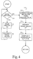
- a calibrating means 110 selectively pulses the reference emitters 106, receives the signals at microphone receivers 14, and processes the elapsed time information in accordance with the procedure of Figure 4. More specifically, the calibration means 110 includes a step or means 112 for causing a first of the reference emitters 106 to emit a signal pulse.
- a step or means 114 acquires the range values D', i.e. the time required for the ultrasonic pulses to traverse the distance D.
- a step or means 116 causes this procedure to be repeated a preselected number of times, such as once for each of the four emitters illustrated in FIGURE 3.
- a step or means 120 corrects the times for fixed machine delays. That is, there is a fixed, small delay between the time when the command is given to fire the reference emitters 106 and the time that they actually produce a detectable ultrasonic signal. Analogously, there is a small delay between the time that the ultrasonic pulses reach the receiver or microphone 14 and the time that it becomes a measurable electrical signal received by the computer processor. These delays are subtracted from the times measured by step or means 114.
- An averaging means 122 averages the actual times after correction for the machine delays for transmission of the ultrasonic pulse between the transmitter and receiver. The time over the range values D' provide the most accurate results.
- a step or means 124 computes a calibration factor F indicative of the current speed of the ultrasound signal adjacent the patient in the operating room.
- the calibration factor F is a ratio of the sonicly measured distance D' versus a precise mechanical measurement of the distance D.
- a wand coordinate and trajectory determining means 130 determines the position of the two emitters 48 and 50, respectively. More specifically, a step or means 132 causes the emitter 48 to emit an ultrasonic signal. The receivers 14 on the frame 12 receive the ultrasonic signal at corresponding times L1-L4. A step or means 134 acquires and retains these times. A step or means 136 causes the second emitter 50 to transmit. A step or means 138 acquires the four times L1-L4 which are required for the ultrasonic signals to pass from the second emitter to the microphones 14. The speed of ultrasonic transmission and accuracy of transmission times are such that these distances can be measured to within a millimeter or better. A step or means 140 causes the emitters to emit and corresponding data values L1-L4 to be acquired each of a plurality of times to improve digitation accuracy, e.g. two times.
- a step or means 142 causes the calibration means 110 to perform the steps described in conjunction with FIGURE 4 in order to provide a current indication of the velocity of sound adjacent to the patient.
- the calibration procedure of FIGURE 4 may be performed immediately before steps 132-138 or intermittently during the collection of several data values for averaging.
- a step or means 144 corrects the values L1-L4 for the fixed machine delay discussed above in conjunction with step or means 120.
- a step or means 146 corrects each of the times L1-L4 that were required for the ultrasonic signals to travel from the first and second emitters 48, 50 to the receivers 14 in accordance with the correction factor F determined by step or means 124.
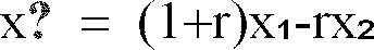
- An averaging means 148 averages the delay and calibration corrected times L1-L4, hence distances between each of the wand emitters 48, 50 and each of the receivers 14. From these distances, provided at least three receivers 14 are provided, a step or means 150 calculates the Cartesian coordinates (x1,y1,z1) and (x2,y2,z2) in the patient space for the two emitters 48 and 50. The first emitter coordinates x1,y1,z1 are calculated from three of the four range values L1-L4.
- the three selected range values are the three shortest of L1-L4. Similar computations are calculated for x2, y2, and z2 coordinates of the second emitter.
- a step or means 152 checks the validity of the measurement.
- the known separation between the wand emitters is compared with the separation between the measured coordinates x1,y1,z1 and x2,y2,z2 of the wand emitters, i.e:
- ⁇ error i.e:
- a step or means 154 from the coordinates of the two emitters 48, 50, and from the geometry of the wand discussed in Figure 2, calculates the Cartesian coordinates (x0,y0,z0) for the wand tip 44.
- the patient space (x,y,z) is aligned with the image space (x',y',z') stored in memory. Aligning the spaces begins with referencing known positions or points 164 in the patient space with the wand tip.
- the tip 44 of the wand may be referenced to three independent positions of the vertebra, i.e. the tips of the spinous and traverse processes. These positions 164 on the vertebra are compared with the relative position of pixels 162 in the image space.
- a transform means 160 transforms the coordinates of the patient space into the coordinate system of the image space.
- Fiducials can also be used by the transform means 160 to transform or match the coordinates of other patient space points 164 into the coordinate system of the image space.
- three or more fiducials or markers are affixed at three or more spaced points on the patient's body.
- the fiducials are visible in the imaging medium selected such that they show up as readily identifiable dots 162 in the resultant image data.
- the fiducials are markers or small beads that are injected with radiation opaque and magnetic resonance excitable materials. A small dot or tattoo is made on the patient's skin and a fiducial is glued to each dot.
- the tip of the wand is placed on each fiducial or tattooed marker point 164.
- the coordinates in patient space of each vertebra process tip or fiducial are determined with the procedure described in conjunction with FIGURES 5A-5C.
- the position of the three fiducials or process tips are compared with the relative position of the pixels 162 in the image space.
- the patient space coordinates of marks 164 or the process tips of the patient in the coordinate system of the patient support are measured.
- a like coordinate system through the pixels 162 is defined and compared to the patient space coordinate system.
- the translation and rotational relationship between image space and patient space coordinate systems is determined. With reference to FIGURE 6A, the position of the patient in operating room space (x,y,z) and the relative position in image space (x',y',z') are determined. That is, two coordinate systems are defined.
- the translation means first determines the offset x offset , y offset , z offset between the barycenters 166, 168 of the triangles defined by the coordinates of three fiducials or process tips in data and patient space, respectively. This provides a translation or an offset in the x, y, and z-directions between the two coordinate systems.
- the values of x offset , y offset , and z offset are added or subtracted to the coordinates of the patient space and the coordinates of image space, respectively, to translate between the two.
- the wand and tool guide can be used to identify the entry coordinate and trajectory at which the surgical tool will be applied to the patient.
- the surgeon may use the wand and tool guide in combination to identify the trajectory and coordinate on the spinal column at which the surgeon will utilize a surgical drill in order to drill a hole for the placement of a spinal screw. Holding the wand and drill guide in one hand, the surgeon moves the combination around the exposed vertebra while viewing images displayed on a monitor selected in accordance with the wand tip.
- the image provide a cross-sectional view of the vertebra and allow the surgeon to plan with greater accuracy the angle and depth at which the drill will be operated.
- the surgeon may remove the wand while holding the tool guide in place. Since the tool guide comes with a handle, the surgeon can hold the tool guide in place even when the spinal column moves in response to patient breathing. In other words, the surgeon can easily hold the bore of the tool guide at the trajectory identified even while the spinal column experiences movement. With the guide properly oriented, the surgeon inserts into the bore the surgical tool and tip needed for the spinal screw fixation. This technique is superior over prior methods in which surgeons relied solely on their own skill and knowledge of the patient's unique anatomy and will result in far fewer sub-optimal results.
- the present invention is also useful in preplanning a surgical operation.
- surgeons may use images of the body portion at which the surgical tool will be inserted in order to determine prior to the operation, the best trajectory and coordinate at which the tool should be applied.
- the computer system can store these images in memory to be later used as a reference target to be compared with images produced in connection with the wand and drill guide.
- the images produced in accordance with the wand and drill guide could be compared with the stored images until the computer identifies an image match. Once the computer identifies a match, the computer can output a signal to alert the surgeon that the tool guide has been properly oriented.
Abstract
In a method and apparatus for orienting and guiding the application of tools, e.g. a surgical tool during carrying out a surgical procedure on a patient, the patient is secured to a subject support (10). A wand (40) is inserted into a tool guide (60). The wand has a tip portion (44), a portion extending along a pointing axis (46) of the wand, an offset portion (42) which is offset from the pointing axis of the wand, and at least two wand emitters (48, 50), mountd in alignment with the pointing axis of the wand. The two emitters selectively emit signals which are received by receivers (14) mounted to a frame assembly (12). The tool guide includes a bore (76) extending along a guide axis. The bore is configured for selectively receiving a tool and the tip portion of the wand. An entry point and a trajectory are identified by the surgeon with the wand in the guide. More specifically, a trajectory and location of the wand are superimposed on a diagnostic image on a monitor (30). If the surgeon is satisfied with the entry point and trajectory shown on the monitor, a surgical tool is inserted into the bore while the tool guide is held along the designated trajectory and at the designated entry point.
Description
- This invention relates to methods and apparatus for orienting and guiding the application of tools. The invention relates especially to such methods and apparatus suitable for use in the medical diagnostic and surgical arts. It finds particular application in conjunction with neurosurgery and will be described with particular reference thereto. However, it is to be appreciated, that the invention will also find application in conjunction with neurobiopsy, CT-table needle body biopsy, breast biopsy, endoscopic procedures, orthopedic surgery, other invasive medical procedures, industrial quality control procedures, and the like.
- Three-dimensional diagnostic image data of the brain, spinal cord, and other body portions is produced by CT scanners, magnetic resonance imagers, and other medical diagnostic equipment. These imaging modalities typically provide structural detail with a resolution of a millimeter or better.
- Various frameless stereotactic procedures have been developed which take advantage of three-dimensional image data of the patient. These procedures include guided-needle biopsies, shunt placements, craniotomies for lesion or tumor resection, and the like. Another area of frameless stereotaxy procedure which requires extreme accuracy is spinal surgery, including screw fixation, fracture decompression, and spinal tumor removal.
- In spinal screw fixation procedures, for example, surgeons or other medical personnel drill and tap a hole in spinal vertebra into which the screw is to be placed. The surgeon relies heavily on his own skill in placing and orienting the bit of the surgical drill prior to forming the hole in the vertebra. Success depends largely upon the surgeon's estimation of anatomical location and orientation in the operative field. This approach has led to suboptimal placement of screws that may injure nerves, blood vessels, or the spinal cord.
- The present invention provides methods and apparatus which overcome the above-referenced problems.
- In accordance with the invention there is provided an apparatus for orienting and guiding the application of a tool into a subject including: a subject support to which a preselected portion of a subject may be secured and which is selectively positionable in a diagnostic imaging system which includes an image memory for storing reconstructed image representations; a display for displaying selected portions of the image representations stored in the image memory in an image coordinate system; a pointer which is selectively touchable to selected portions of the subject or subject support; an electronic position indicator for providing an electronic indication of points of the subject or subject support portions touched by the pointer in a subject coordinate system; and means for correlating the subject coordinate system with the image coordinate system; the apparatus being characterised by a guide for defining a path extending longitudinally along a guide axis, the guide being configured for selectively receiving a tool along the guide axis; and means connected with the guide for providing electronic signals to the correlating means for coordinating a coordinate system of the guide with the image coordinate system.
- The invention also provides a method of orienting a tool and guiding an application of the tool into a subject in which a pointer and guide in combination are maneuvered to a proposed entry point and a trajectory for application of the tool is defined; the method including electronically signaling the trajectory and entry point; correlating a coordinate system of the subject and the signaled entry point and trajectory with a coordinate system of an electronic image representation stored in an image memory; and generating a human-readable display of at least a portion of the image representation with the trajectory and entry point superimposed thereon, the method being characterised by: defining with the guide a tool receiving guide path disposed in alignment with the trajectory; and inserting the tool along the guide path and into the subject along the trajectory through the proposed entry point.
- One apparatus and method in accordance with the invention and modifications thereof will now be described, by way of example, with reference to the accompanying drawings in which:-
- FIGURE 1A is a perspective view of an operating room in which the apparatus is deployed;
- FIGURE 1B is a block diagram of an image data manipulation of the apparatus of FIGURE 1A;
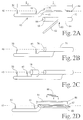
- FIGURES 2A, 2B, 2C, 2D, 2E, 2F, and 2G illustrate various embodiments of a wand and guide forming part of the apparatus;
- FIGURE 3 is a detailed illustration of a locator assembly of the apparatus;
- FIGURE 4 is a diagrammatic illustration of one embodiment of calibration procedure used in the apparatus and method;
- FIGURES 5A and 5B are diagrammatic illustrations of the wand and locator assembly relationship;
- FIGURES 5C is a flow diagram of a wand location procedure; and
- FIGURES 6A, 6B, 6C, and 6D are illustrative of a coordinate transform used in the apparatus and method.
- With reference to FIGURE 1A, a subject, such as a human patient, is received on an operating table or
other subject support 10 and appropriately positioned within the operating room. Aframe 12 is mounted in a fixed relationship to the patient such that it is precisely positioned within the subject or subject support coordinate system. In the illustrated embodiment, theframe 12 is mounted to thepatient support 10. Mounting theframe 12 to the patient support permits the patient support to be turned, raised, lowered, wheeled to another location, or the like, without altering the patient coordinate system. Alternately, the support may be mounted to a pole or other stationary support, the ceiling of the room, or the like. Theframe 12 supports a plurality ofreceivers 14 such as microphones, radio frequency receivers, light sensitive diodes, other light sensitive receivers, and the like mounted at fixed, known locations thereon. A securing means such as ahead clamp 16, securely positions a portion of the subject under consideration. The frame is mounted at a fixed or selectable angle from vertical such that the frame is positionable more toward the patient, yet still focusing on the region of interest of the patient. - With continuing reference to FIGURE 1A and further reference to FIGURE 1B, an
operator console 18 houses a computer system 20. Alternately, the computer system can be remotely located and connected with thecontrol console 18 by cabling. The computer system includes a three-dimensional data memory 22. The stored three-dimensional image data preferably contains a video pixel value for each voxel or point in a three-dimensional rectangular grid of points, preferably a 256 x 256 x 256 grid. When each image value represents one millimeter cube, the image data represents about a 25.6 centimeter cube through the patient with one millimeter resolution. Because the data is in a three-dimensional rectangular grid, selectable orthogonal and other oblique planes of the data can readily be withdrawn from the three-dimensional memory using conventional technology. A plane selecting means 24 selects various two-dimensional planes of pixel values from the three-dimensional memory for display. - The plane selecting means selects at least three planes: axial, sagittal, coronal, and oblique planes through a selectable point of the patient. The pixel values which lie on the selected axial, sagittal, coronal, and oblique planes are copied into
corresponding image memories TV monitor 30 or other appropriate display means. - With continuing reference to FIGURE 1A and further reference to FIGURE 2A, a
wand 40, formed of suitable resilient material such as metal, has anoffset 42 near a tip portion orproximal end 44. Theoffset 42 is connected to a portion extending along apointing axis 46 of the wand. In this preferred embodiment, a pair ofemitters pointing axis 46 of the wand. The emitters emit a signal that is received by thereceivers 14, such as a spark emitter, radio frequency transmitter, infrared LED, or the like. Thefirst emitter 48 is a fixed known distance ℓ₁ from thetip 44 and thesecond emitter 50 is a fixed known distance ℓ₂ from thefirst emitter 48. The wand is readily sterilized by conventional techniques.Emitters - The
wand 40 is used in conjunction with aguide 60 to designate a coordinate and trajectory at which a surgical tool will be applied to the patient. The guide can be any guide or appliance which positions thewand 40 to establish a surgical trajectory. In the preferred embodiment, theguide 60 is a portable tool which has ahandle 62 and atube member 64 which defines aninternal bore 66 to receive and accurately position the wand. Thebore 66 of the tool guide has a diameter which allows for the non-simultaneous insertion of either thewand 40 or a surgical tool such as a drill, biopsy needle, and the like. Rather than being hand-held, theguide 60 can be mounted to other structures in the operating room, e.g. framed stereotaxic equipment. In intraoperative use, thewand 40 is inserted in the tool guide bore until thetip 44 aligns with a tool guidedistal end 72. Awand stop 70 is positioned on the wand and abuts aproximal end surface 68 of the tool guide when the wand tip aligns with thedistal end 72. With the wand tip aligned with the tool guide end, the surgeon may commence probing the patient to seek an optimal coordinate and trajectory in which to insert the appropriate surgical tool. To this end, the surgeon maneuvers the wand and tool guide in combination to a proposed trajectory and actuates the emitters. Signals from the emitters are used in calculating thetrajectory 46 and theend point 44 of the wand. The trajectory and end point are displayed on themonitor 30 superimposed on the three-dimensional image or selected image planes. The details of the process for correlating the coordinate system of the patient and the wand with the coordinate system of the image data is described below. - By viewing the
display 30, the surgeon can identify the location of the wand tip with respect to anatomic structure, and the trajectory of the bore. If the trajectory is satisfactory, the wand is removed, the surgical tool is inserted, and the procedure is performed. If the trajectory is unsatisfactory, the wand is repositioned and its new trajectory determined and evaluated. This approach improves surgical planning when compared with prior approaches in which surgeons relied solely on their own estimation of the patient's anatomy. Following the identification of the appropriate trajectory and coordinate, thewand 40 is removed from thebore 66 of theguide 60 while the guide is held in position. Holding theguide 60 steady preserves the appropriate trajectory and position coordinates in the axial and sagittal planes determined by the wand. Thereafter, the appropriate surgical tool or appliance is inserted within theguide 60. With this approach, the surgical tool is properly positioned in the appropriate trajectory required to perform the surgical procedure. - The wand and tool guide are particularly useful in accurately identifying the optimal entry point, trajectory, and depth of insertion of screws to be placed into the patient's spinal column, as will be more fully described below.
- With reference to FIGURES 2B, 2C, and 2D alternative embodiments of the present invention are shown in which the guide is integrated into the wand. In general, each of the alternative embodiments contain a wand offset portion on which are mounted two or more emitters for emitting positioning signals. As in the preferred embodiment,
emitters axis 46 of the wand. However, in the alternative embodiments, the central axis or pointingdirection 46 aligns with a longitudinal axis of the guide means formed integrally with the wand. In each of the alternative embodiments, the guide means is connected to the wand offset portion via an extension. - With reference to FIGURE 2B, a
tubular portion 74 is integrated with the wand. The tubular portion defines abore 76 extending along its longitudinal axis. In intraoperative use, the surgeon probes the patient with the proximal seeking to locate the proper coordinate and trajectory for the surgical tool. Once the coordinate and trajectory are located, the surgeon holds the offset portion while the surgical tool is inserted within the tube. Thereafter, the surgical tool is operated to perform the surgical procedure. - With reference to FIGURE 2C, a second alterative embodiment is shown similar to the previously described alternative embodiment. However, in addition to the structure previously described, a
laser 78 is mounted to the offset portion. Light emitting from the laser travels along thelongitudinal pointing axis 46 of thebore 76 of the tubular member. In intraoperative use, the surgeon maneuvers the integrated wand and laser while viewing images displayed on themonitor 30. The images selected for display are based upon the coordinate and trajectory of the bore center point at the proximal end of the integrated wand. Once a proper coordinate and trajectory are identified, the integrated wand is held in place while the surgeon activates the laser. Light emitting from the laser intersects the bore center point at the proximal end. - With reference to FIGURE 2D, a third embodiment is shown in which a grooved
guide member portion 80 is incorporated into the wand. The grooved member is connected to the offset portion. The grooved member contains agroove 82 having a longitudinal axis which is in line with pointingaxis 46 of the wand. This alternative embodiment finds particular usefulness in conjunction with needle biopsies. In intraoperative use, abiopsy needle 84 is positioned within the groove so that atip 86 of the biopsy needle aligns with the groove center point at the proximal end of the integrated wand. The biopsy needle is held in place by a restraining means such as Velcro® straps 88 attached to the sides of the grooved member. - In the embodiment of Figure 2E, the
wand 40 hasemitters 50, 50', 50'' mounted off theaxis 46. Because the relationship between the emitter location and theaxis 46 is fixed, once the emitters are located, theaxis 46 is determined. - In the embodiment of Figure 2F, there are more than two
emitters axis 46, greater accuracy is obtained by redundantly determining theaxis 46 and averaging the results. Preferably, a least squares fit is used to compensate for any deviation in theaxis 46 determined by the various emitter pairs. - In the embodiment of Figure 2G, the
wand 40 has interchangeable tips. Thewand 40 includes afirst connector portion 90 which selectively connects with asecond connector portion 92 of the tips. Various connector systems are contemplated such as a threaded bore and threaded shaft, a snap lock connector means, bayonet connector, spring lock, or other connector systems. A key andkeyway system 94 or other means for fixing the alignment of the tips and the wand is particularly advantageous when the connector is off theaxis 46. - Various tips are contemplated. A
short tip 96 is provided for accurate registration. Alonger tip 98 facilitates reaching deeper into interior regions of the subject. Tubular drill guides 100 can be provided in various diameters to accommodate different size drills. Anadapter 102 enables endoscopes and other tools to be attached to the wand. Tools and equipment, such as an array ofultrasonic transducers 104, can be connected to theadaptor 102 or configured for direct connection to the wand. A wide variety of other tips for various applications are also contemplated. - The preferred embodiment uses the
stereotaxic wand 40 to align the coordinate system of the operating room including the patient, the tool guide, and wand with the coordinate system of a previously prepared three-dimensional image stored in memory. Prior to identifying the proper coordinate and trajectory of the tool guide, the patient space is aligned with or referenced to the stored three-dimensional image data preferably using the following technique. - With reference to Figure 3, when the
receivers 14 are microphones, a plurality ofreference emitters 106 are mounted on theframe 12. The reference receivers are each spaced along side edges of the frame by known distances from adjacent receivers ormicrophones 14, e.g. by distances S₁ and S₂. Preferably S₁=S₂=S. Each reference receiver is also spaced by a distance D across the frame from an oppositely disposed emitter. - The distance from the wand emitters to the frame, hence the position of the wand relative to the patient, is determined by the travel time of the sound. The velocity of the sound pulse through air is dependent upon both the temperature, the humidity, and the chemical composition of the air. These factors can and do vary significantly during an operation and from procedure to procedure. As shown in Figure 4, a calculation is performed to determine the speed of sound in the operating room. A calibrating means 110 selectively pulses the
reference emitters 106, receives the signals atmicrophone receivers 14, and processes the elapsed time information in accordance with the procedure of Figure 4. More specifically, the calibration means 110 includes a step or means 112 for causing a first of thereference emitters 106 to emit a signal pulse. A step or means 114 acquires the range values D', i.e. the time required for the ultrasonic pulses to traverse the distance D. A step or means 116 causes this procedure to be repeated a preselected number of times, such as once for each of the four emitters illustrated in FIGURE 3. - Once the travel time between each emitter and receiver pair has been obtained a preselected number of times, a step or means 120 corrects the times for fixed machine delays. That is, there is a fixed, small delay between the time when the command is given to fire the
reference emitters 106 and the time that they actually produce a detectable ultrasonic signal. Analogously, there is a small delay between the time that the ultrasonic pulses reach the receiver ormicrophone 14 and the time that it becomes a measurable electrical signal received by the computer processor. These delays are subtracted from the times measured by step or means 114. An averaging means 122 averages the actual times after correction for the machine delays for transmission of the ultrasonic pulse between the transmitter and receiver. The time over the range values D' provide the most accurate results. A step or means 124 computes a calibration factor F indicative of the current speed of the ultrasound signal adjacent the patient in the operating room. In the preferred embodiment, the calibration factor F is a ratio of the sonicly measured distance D' versus a precise mechanical measurement of the distance D. - With reference to Figures 5A, 5B, and 5C, a wand coordinate and trajectory determining means 130 determines the position of the two
emitters emitter 48 to emit an ultrasonic signal. Thereceivers 14 on theframe 12 receive the ultrasonic signal at corresponding times L₁-L₄. A step or means 134 acquires and retains these times. A step or means 136 causes thesecond emitter 50 to transmit. A step or means 138 acquires the four times L₁-L₄ which are required for the ultrasonic signals to pass from the second emitter to themicrophones 14. The speed of ultrasonic transmission and accuracy of transmission times are such that these distances can be measured to within a millimeter or better. A step or means 140 causes the emitters to emit and corresponding data values L₁-L₄ to be acquired each of a plurality of times to improve digitation accuracy, e.g. two times. - When sonic emitters are used, a step or means 142 causes the calibration means 110 to perform the steps described in conjunction with FIGURE 4 in order to provide a current indication of the velocity of sound adjacent to the patient. Of course, the calibration procedure of FIGURE 4 may be performed immediately before steps 132-138 or intermittently during the collection of several data values for averaging. A step or means 144 corrects the values L₁-L₄ for the fixed machine delay discussed above in conjunction with step or means 120. A step or means 146 corrects each of the times L₁-L₄ that were required for the ultrasonic signals to travel from the first and
second emitters receivers 14 in accordance with the correction factor F determined by step or means 124. An averaging means 148 averages the delay and calibration corrected times L₁-L₄, hence distances between each of thewand emitters receivers 14. From these distances, provided at least threereceivers 14 are provided, a step or means 150 calculates the Cartesian coordinates (x₁,y₁,z₁) and (x₂,y₂,z₂) in the patient space for the twoemitters 


where S=S₁=S₂ as defined in FIGURE 3. Preferably, the three selected range values are the three shortest of L₁-L₄. Similar computations are calculated for x₂, y₂, and z₂ coordinates of the second emitter. A step or means 152 checks the validity of the measurement. More specifically, the known separation between the wand emitters is compared with the separation between the measured coordinates x₁,y₁,z₁ and x₂,y₂,z₂ of the wand emitters, i.e:
- If the measured and known separation is greater than the acceptable error, e.g. 0.75 mm when measuring with a resolution of 1 mm, an erroneous measurement signal is given. The measurement is discarded and the surgeon or other user is flagged to perform the
measurement process 130 again. A step or means 154 from the coordinates of the twoemitters wand tip 44. - The tip coordinates x₀, y₀, z₀ are defined by:


- Before the wand and tool guide can be used to locate a proper coordinate and trajectory for a surgical tool such as a drill, the patient space (x,y,z) is aligned with the image space (x',y',z') stored in memory. Aligning the spaces begins with referencing known positions or points 164 in the patient space with the wand tip. For example, the
tip 44 of the wand may be referenced to three independent positions of the vertebra, i.e. the tips of the spinous and traverse processes. Thesepositions 164 on the vertebra are compared with the relative position ofpixels 162 in the image space. Thereafter, with reference to FIGURE 6, a transform means 160, as shown in FIGURE 6, transforms the coordinates of the patient space into the coordinate system of the image space. Fiducials can also be used by the transform means 160 to transform or match the coordinates of other patient space points 164 into the coordinate system of the image space. To this end, three or more fiducials or markers are affixed at three or more spaced points on the patient's body. The fiducials are visible in the imaging medium selected such that they show up as readilyidentifiable dots 162 in the resultant image data. The fiducials are markers or small beads that are injected with radiation opaque and magnetic resonance excitable materials. A small dot or tattoo is made on the patient's skin and a fiducial is glued to each dot. This enables theposition 164 of the fiducials to be denoted even if the fiducials are removed in the interval between the collection of the image data and the surgical procedure. To align the images of the fiducials with the fiducial positions in patient space, the tip of the wand is placed on each fiducial or tattooedmarker point 164. The coordinates in patient space of each vertebra process tip or fiducial are determined with the procedure described in conjunction with FIGURES 5A-5C. - The position of the three fiducials or process tips are compared with the relative position of the
pixels 162 in the image space. The patient space coordinates ofmarks 164 or the process tips of the patient in the coordinate system of the patient support are measured. A like coordinate system through thepixels 162 is defined and compared to the patient space coordinate system. The translation and rotational relationship between image space and patient space coordinate systems is determined. With reference to FIGURE 6A, the position of the patient in operating room space (x,y,z) and the relative position in image space (x',y',z') are determined. That is, two coordinate systems are defined. The translation means first determines the offset xoffset, yoffset, zoffset between thebarycenters - With reference to Figure 6B, translating the origins of the two coordinate systems into alignment, however, is not the complete correction. Rather, the coordinate systems are normally also rotated relative to each other about all three axes whose origin is at the barycenter. As illustrated in Figures 6B, 6C, and 6D, the angle of rotation in the (y,z), (x,z), and (x,y) planes are determined. Having made these determinations, it is a simple matter to transform the patient support space coordinates into the image space coordinates and, conversely, to rotate the image space coordinates into patient space coordinates. The wand coordinate means 130 is connected through the transform means 160 with one of the
plane selecting means 24 and the video processor 28 to cause a marker, e.g. cross hairs, to be displayed on themonitors 30 at the coordinates of the wand tip. This enables the surgeon to coordinate specific points on the patient or in the incision with the images. - Having aligned the image and patient spaces the wand and tool guide can be used to identify the entry coordinate and trajectory at which the surgical tool will be applied to the patient. For example, the surgeon may use the wand and tool guide in combination to identify the trajectory and coordinate on the spinal column at which the surgeon will utilize a surgical drill in order to drill a hole for the placement of a spinal screw. Holding the wand and drill guide in one hand, the surgeon moves the combination around the exposed vertebra while viewing images displayed on a monitor selected in accordance with the wand tip. The image provide a cross-sectional view of the vertebra and allow the surgeon to plan with greater accuracy the angle and depth at which the drill will be operated. Once the coordinate and trajectory of the drill application is identified, the surgeon may remove the wand while holding the tool guide in place. Since the tool guide comes with a handle, the surgeon can hold the tool guide in place even when the spinal column moves in response to patient breathing. In other words, the surgeon can easily hold the bore of the tool guide at the trajectory identified even while the spinal column experiences movement. With the guide properly oriented, the surgeon inserts into the bore the surgical tool and tip needed for the spinal screw fixation. This technique is superior over prior methods in which surgeons relied solely on their own skill and knowledge of the patient's unique anatomy and will result in far fewer sub-optimal results.
- The present invention is also useful in preplanning a surgical operation. For example, surgeons may use images of the body portion at which the surgical tool will be inserted in order to determine prior to the operation, the best trajectory and coordinate at which the tool should be applied. Once the proper trajection and coordinate are identified, the computer system can store these images in memory to be later used as a reference target to be compared with images produced in connection with the wand and drill guide. In particular, the images produced in accordance with the wand and drill guide could be compared with the stored images until the computer identifies an image match. Once the computer identifies a match, the computer can output a signal to alert the surgeon that the tool guide has been properly oriented.
Claims (10)
- An apparatus for orienting and guiding the application of a tool into a subject including: a subject support (10) to which a preselected portion of a subject may be secured and which is selectively positionable in a diagnostic imaging system which includes an image memory (22) for storing reconstructed image representations; a display (30) for displaying selected portions of the image representations stored in the image memory in an image coordinate system (x',y',z'); a pointer (44) which is selectively touchable to selected portions of the subject or subject support (10); an electronic position indicator (48, 50) for providing an electronic indication of points (164) of the subject or subject support portions touched by the pointer in a subject coordinate system (x,y,z); and means (160) for correlating the subject coordinate system (x, y, z) with the image coordinate system (x', y', z') the apparatus being characterised by: a guide (60) for defining a path extending longitudinally along a guide axis (46), the guide (60) being configured for selectively receiving a tool (84) along the guide axis (46); and means (48, 50) connected with the guide (60) for providing electronic signals to the correlating means (160) for coordinating a coordinate system of the guide (60) with the image coordinate system (x', y', z').
- An apparatus as set forth in Claim 1 wherein the guide (60) is configured for selectively receiving the pointer (44) and has means (90, 92, 94) for locking the pointer (44) in a preselected position relative to the guide axis (46).
- An apparatus as set forth in Claim 1 wherein the guide (60) has at least a pair of emitters (48, 50) for selectively emitting signals which are transmitted through the air; and the apparatus further includes receivers (14) for receiving the signals from the emitters (48, 50); and a ranging means (110) for determining the position of the emitters (48, 50) in the subject coordinate system.
- An apparatus as set forth in Claim 3 wherein the guide (60) includes a groove or bore (76, 82, 100) for receiving the tool (84) and wherein the emitters (48, 50) are mounted in a preselected location relative to the groove or bore (76, 82, 100) such that the ranging means (110) determines a trajectory along the groove or bore (76, 82, 100).
- An apparatus as set forth in Claim 2 further including a plurality of guide tips (96, 98, 100, 102, 104) and means (90, 92, 94) for selectively connecting the tips to the guide (60), at least one of the tips (96) being configured such that a pointing axis of the tip is in alignment with the guide axis (46).
- An apparatus as set forth in any of the preceding claims further including a laser (78) mounted for outputting light along the path defined by the guide axis (46).
- An apparatus as set forth in any of the preceding claims wherein the guide (60) includes: a guide portion (74, 80) for receiving the tool (84) along the guide axis (46); a handle (62) for holding the guide portion; and means (48, 50) for signaling the guide axis.
- An apparatus as set forth in any of the preceding claims wherein the guide (60) includes an interconnection means (64, 70) for selective interconnection with a wand (40) that carries the pointer (44) and emitters (48, 50) for signaling a location of the pointer in the subject coordinate system.
- A method of orienting a tool (84) and guiding an application of the tool (84) into a subject in which a pointer (44) and guide (60) in combination are manoeuvered to a proposed entry point and a trajectory (46) for application of the tool (84) is defined; the method including electronically signaling the trajectory and entry point; correlating (160) a coordinate system of the subject and the signaled entry point and trajectory with a coordinate system of an electronic image representation stored in an image memory; and generating a human-readable display (30) of at least a portion of the image representation with the trajectory and entry point superimposed thereon, the method being characterised by: defining with the guide (60, 80) a tool receiving guide path (66, 76, 82) disposed in alignment with the trajectory; and inserting the tool (84) along the guide path (66, 76, 82) and into the subject along the trajectory through the proposed entry point.
- A method as set forth in Claim 9 including inserting into the guide (60, 80) a wand (40) which carries a pair of emitters (48, 50) for signaling the trajectory and a location of its tip (44) in the guide (60); positioning the guide (60) such that the tip (44) of the wand touches the proposed entry point; and, after correlating the entry point and the trajectory with the electronic image representation, removing at least a pointer portion of the wand from the guide (60) prior to inserting the tool (84) into the guide (60).
Applications Claiming Priority (2)
| Application Number | Priority Date | Filing Date | Title |
|---|---|---|---|
| US224955 | 1994-04-08 | ||
| US08/224,955 US5517990A (en) | 1992-11-30 | 1994-04-08 | Stereotaxy wand and tool guide |
Publications (1)
| Publication Number | Publication Date |
|---|---|
| EP0676178A1 true EP0676178A1 (en) | 1995-10-11 |
Family
ID=22842926
Family Applications (1)
| Application Number | Title | Priority Date | Filing Date |
|---|---|---|---|
| EP95301778A Withdrawn EP0676178A1 (en) | 1994-04-08 | 1995-03-16 | Apparatus for orienting and guiding the application of tools |
Country Status (3)
| Country | Link |
|---|---|
| US (3) | US5517990A (en) |
| EP (1) | EP0676178A1 (en) |
| JP (1) | JP4202434B2 (en) |
Cited By (23)
| Publication number | Priority date | Publication date | Assignee | Title |
|---|---|---|---|---|
| WO1998037827A2 (en) * | 1997-02-28 | 1998-09-03 | Koninklijke Philips Electronics N.V. | Image-guided surgery system |
| EP0905538A2 (en) | 1997-09-26 | 1999-03-31 | Picker International, Inc. | Microscope calibration |
| EP0904735A2 (en) | 1997-09-26 | 1999-03-31 | Picker International, Inc. | Tool calibration |
| EP0908146A2 (en) * | 1997-10-06 | 1999-04-14 | General Electric Company | Real-time image-guided placement of anchor devices |
| EP0911668A2 (en) | 1997-09-26 | 1999-04-28 | Picker International, Inc. | Microscope calibration |
| EP0922438A1 (en) * | 1997-11-28 | 1999-06-16 | Picker International, Inc. | Image guided interventional procedures |
| WO1999029253A1 (en) * | 1997-12-12 | 1999-06-17 | Surgical Navigation Technologies, Inc. | Image guided spinal surgery guide, system, and method for use thereof |
| US6006127A (en) * | 1997-02-28 | 1999-12-21 | U.S. Philips Corporation | Image-guided surgery system |
| EP0920838A3 (en) * | 1997-12-08 | 2000-02-23 | The Cleveland Clinic Foundation | Fiducial cup |
| EP0995406A1 (en) * | 1998-10-23 | 2000-04-26 | Picker International, Inc. | Method and apparatus for planning surgical procedures |
| WO2000049958A1 (en) * | 1999-02-22 | 2000-08-31 | Vtarget Ltd. | A method and system for guiding a diagnostic or therapeutic instrument towards a target region inside the patient's body |
| WO2002067783A2 (en) * | 2001-02-27 | 2002-09-06 | Smith & Nephew, Inc. | Total knee arthroplasty systems and processes |
| EP1732647A2 (en) * | 2004-04-06 | 2006-12-20 | Incorporated Accuray | Treatment target positioning system |
| EP1854425A1 (en) * | 2006-05-11 | 2007-11-14 | BrainLAB AG | Position determination for medical devices with redundant position measurement and weighting to prioritise measurements |
| WO2008062485A1 (en) * | 2006-11-22 | 2008-05-29 | Health Robotics S.R.L. | Device for detecting elongated bodies |
| US7764985B2 (en) | 2003-10-20 | 2010-07-27 | Smith & Nephew, Inc. | Surgical navigation system component fault interfaces and related processes |
| US7794467B2 (en) | 2003-11-14 | 2010-09-14 | Smith & Nephew, Inc. | Adjustable surgical cutting systems |
| US7862570B2 (en) | 2003-10-03 | 2011-01-04 | Smith & Nephew, Inc. | Surgical positioners |
| US7996064B2 (en) | 1999-03-23 | 2011-08-09 | Medtronic Navigation, Inc. | System and method for placing and determining an appropriately sized surgical implant |
| US8109942B2 (en) | 2004-04-21 | 2012-02-07 | Smith & Nephew, Inc. | Computer-aided methods, systems, and apparatuses for shoulder arthroplasty |
| US8177788B2 (en) | 2005-02-22 | 2012-05-15 | Smith & Nephew, Inc. | In-line milling system |
| CN107049695A (en) * | 2017-05-25 | 2017-08-18 | 闻公灵 | A kind of Neurology separate diagnostic chair |
| CN109124962A (en) * | 2018-07-27 | 2019-01-04 | 刘兆勇 | A kind of Intelligent orthopaedic operating table |
Families Citing this family (301)
| Publication number | Priority date | Publication date | Assignee | Title |
|---|---|---|---|---|
| US6331180B1 (en) | 1988-05-03 | 2001-12-18 | Sherwood Services Ag | Target-centered stereotaxtic surgical arc system with reorientatable arc axis |
| FR2652928B1 (en) | 1989-10-05 | 1994-07-29 | Diadix Sa | INTERACTIVE LOCAL INTERVENTION SYSTEM WITHIN A AREA OF A NON-HOMOGENEOUS STRUCTURE. |
| US6347240B1 (en) | 1990-10-19 | 2002-02-12 | St. Louis University | System and method for use in displaying images of a body part |
| US6006126A (en) | 1991-01-28 | 1999-12-21 | Cosman; Eric R. | System and method for stereotactic registration of image scan data |
| US6405072B1 (en) * | 1991-01-28 | 2002-06-11 | Sherwood Services Ag | Apparatus and method for determining a location of an anatomical target with reference to a medical apparatus |
| US5603318A (en) | 1992-04-21 | 1997-02-18 | University Of Utah Research Foundation | Apparatus and method for photogrammetric surgical localization |
| US5913820A (en) | 1992-08-14 | 1999-06-22 | British Telecommunications Public Limited Company | Position location system |
| US6757557B1 (en) | 1992-08-14 | 2004-06-29 | British Telecommunications | Position location system |
| US5517990A (en) * | 1992-11-30 | 1996-05-21 | The Cleveland Clinic Foundation | Stereotaxy wand and tool guide |
| US5732703A (en) * | 1992-11-30 | 1998-03-31 | The Cleveland Clinic Foundation | Stereotaxy wand and tool guide |
| EP0699050B1 (en) * | 1993-04-26 | 2004-03-03 | St. Louis University | Indicating the position of a probe |
| GB9405299D0 (en) * | 1994-03-17 | 1994-04-27 | Roke Manor Research | Improvements in or relating to video-based systems for computer assisted surgery and localisation |
| EP0951874A3 (en) | 1994-09-15 | 2000-06-14 | Visualization Technology, Inc. | Position tracking and imaging system for use in medical applications using a reference unit secured to a patients head |
| US5829444A (en) * | 1994-09-15 | 1998-11-03 | Visualization Technology, Inc. | Position tracking and imaging system for use in medical applications |
| US5695501A (en) | 1994-09-30 | 1997-12-09 | Ohio Medical Instrument Company, Inc. | Apparatus for neurosurgical stereotactic procedures |
| US6978166B2 (en) * | 1994-10-07 | 2005-12-20 | Saint Louis University | System for use in displaying images of a body part |
| JP3492697B2 (en) | 1994-10-07 | 2004-02-03 | セントルイス ユニバーシティー | Surgical guidance device with reference and localization frame |
| US5682890A (en) * | 1995-01-26 | 1997-11-04 | Picker International, Inc. | Magnetic resonance stereotactic surgery with exoskeleton tissue stabilization |
| US5797849A (en) * | 1995-03-28 | 1998-08-25 | Sonometrics Corporation | Method for carrying out a medical procedure using a three-dimensional tracking and imaging system |
| US5817022A (en) * | 1995-03-28 | 1998-10-06 | Sonometrics Corporation | System for displaying a 2-D ultrasound image within a 3-D viewing environment |
| US5868673A (en) * | 1995-03-28 | 1999-02-09 | Sonometrics Corporation | System for carrying out surgery, biopsy and ablation of a tumor or other physical anomaly |
| US5795298A (en) * | 1995-03-28 | 1998-08-18 | Sonometrics Corporation | System for sharing electrocardiogram electrodes and transducers |
| US6246898B1 (en) | 1995-03-28 | 2001-06-12 | Sonometrics Corporation | Method for carrying out a medical procedure using a three-dimensional tracking and imaging system |
| US5830144A (en) * | 1995-03-28 | 1998-11-03 | Vesely; Ivan | Tracking data sheath |
| US5752513A (en) * | 1995-06-07 | 1998-05-19 | Biosense, Inc. | Method and apparatus for determining position of object |
| US5592939A (en) | 1995-06-14 | 1997-01-14 | Martinelli; Michael A. | Method and system for navigating a catheter probe |
| CH691569A5 (en) * | 1995-10-12 | 2001-08-31 | Zeiss Carl | Medical therapy and / or diagnostic device with sterilizable Positionserfassungsaufsetzteil. |
| US6167145A (en) | 1996-03-29 | 2000-12-26 | Surgical Navigation Technologies, Inc. | Bone navigation system |
| US5680861A (en) * | 1996-07-08 | 1997-10-28 | General Electric Company | Modular subject positioning system for medical imaging |
| US6226418B1 (en) | 1997-11-07 | 2001-05-01 | Washington University | Rapid convolution based large deformation image matching via landmark and volume imagery |
| US6408107B1 (en) | 1996-07-10 | 2002-06-18 | Michael I. Miller | Rapid convolution based large deformation image matching via landmark and volume imagery |
| US6364888B1 (en) * | 1996-09-09 | 2002-04-02 | Intuitive Surgical, Inc. | Alignment of master and slave in a minimally invasive surgical apparatus |
| SE9603314D0 (en) * | 1996-09-12 | 1996-09-12 | Siemens Elema Ab | Method and apparatus for determining the location of a catheter within the body of a patient |
| US5980535A (en) | 1996-09-30 | 1999-11-09 | Picker International, Inc. | Apparatus for anatomical tracking |
| EP0832610A3 (en) | 1996-09-30 | 1999-06-16 | Picker International, Inc. | Trackable guide for surgical tool |
| US6142937A (en) * | 1996-10-11 | 2000-11-07 | Carl-Zeiss-Stiftung | Medical therapeutic and/or diagnostic appliance with a sterilizable position sensing attachment |
| GB9624399D0 (en) | 1996-11-23 | 1997-01-08 | Marconi Gec Ltd | Device for use with nuclear magnetic resonance imaging apparatus |
| US7302288B1 (en) | 1996-11-25 | 2007-11-27 | Z-Kat, Inc. | Tool position indicator |
| US5810008A (en) * | 1996-12-03 | 1998-09-22 | Isg Technologies Inc. | Apparatus and method for visualizing ultrasonic images |
| US6032066A (en) * | 1997-02-07 | 2000-02-29 | Jcrt Radiation Oncology Support Services | Method and apparatus for virtual radiotherapy beam projection localization in real space |
| US5880976A (en) * | 1997-02-21 | 1999-03-09 | Carnegie Mellon University | Apparatus and method for facilitating the implantation of artificial components in joints |
| US6205411B1 (en) | 1997-02-21 | 2001-03-20 | Carnegie Mellon University | Computer-assisted surgery planner and intra-operative guidance system |
| US6019725A (en) * | 1997-03-07 | 2000-02-01 | Sonometrics Corporation | Three-dimensional tracking and imaging system |
| USD422706S (en) * | 1997-04-30 | 2000-04-11 | Surgical Navigation Technologies | Biopsy guide tube |
| US6752812B1 (en) | 1997-05-15 | 2004-06-22 | Regent Of The University Of Minnesota | Remote actuation of trajectory guide |
| US6267769B1 (en) | 1997-05-15 | 2001-07-31 | Regents Of The Universitiy Of Minnesota | Trajectory guide method and apparatus for use in magnetic resonance and computerized tomographic scanners |
| US6434507B1 (en) | 1997-09-05 | 2002-08-13 | Surgical Navigation Technologies, Inc. | Medical instrument and method for use with computer-assisted image guided surgery |
| US6226548B1 (en) | 1997-09-24 | 2001-05-01 | Surgical Navigation Technologies, Inc. | Percutaneous registration apparatus and method for use in computer-assisted surgical navigation |
| USD420132S (en) * | 1997-11-03 | 2000-02-01 | Surgical Navigation Technologies | Drill guide |
| AUPP031097A0 (en) * | 1997-11-10 | 1997-12-04 | Clift, Vaughan | Skin impedance imaging system |
| US6021343A (en) | 1997-11-20 | 2000-02-01 | Surgical Navigation Technologies | Image guided awl/tap/screwdriver |
| US5967982A (en) * | 1997-12-09 | 1999-10-19 | The Cleveland Clinic Foundation | Non-invasive spine and bone registration for frameless stereotaxy |
| US6119032A (en) * | 1997-12-31 | 2000-09-12 | U.S. Philips Corporation | Method and system for positioning an invasive device by magnetic resonance (MR) imaging of an MR visible device |
| DE19813383A1 (en) | 1998-03-26 | 1999-10-07 | Storz Karl Gmbh & Co | Device with a transmitter unit, via which the position of a medical instrument can be detected in the context of a CAS system |
| US6546277B1 (en) * | 1998-04-21 | 2003-04-08 | Neutar L.L.C. | Instrument guidance system for spinal and other surgery |
| US6529765B1 (en) | 1998-04-21 | 2003-03-04 | Neutar L.L.C. | Instrumented and actuated guidance fixture for sterotactic surgery |
| US6273896B1 (en) | 1998-04-21 | 2001-08-14 | Neutar, Llc | Removable frames for stereotactic localization |
| US6298262B1 (en) | 1998-04-21 | 2001-10-02 | Neutar, Llc | Instrument guidance for stereotactic surgery |
| CN1371257A (en) * | 1998-06-15 | 2002-09-25 | 明拉德股份有限公司 | Method and device for determining access to subsurface target |
| ES2304794T3 (en) | 1998-06-22 | 2008-10-16 | Ao Technology Ag | PAREO OF LOCATION THROUGH LOCALIZATION SCREWS. |
| US6118845A (en) | 1998-06-29 | 2000-09-12 | Surgical Navigation Technologies, Inc. | System and methods for the reduction and elimination of image artifacts in the calibration of X-ray imagers |
| US6351662B1 (en) | 1998-08-12 | 2002-02-26 | Neutar L.L.C. | Movable arm locator for stereotactic surgery |
| US6282437B1 (en) | 1998-08-12 | 2001-08-28 | Neutar, Llc | Body-mounted sensing system for stereotactic surgery |
| US6477400B1 (en) * | 1998-08-20 | 2002-11-05 | Sofamor Danek Holdings, Inc. | Fluoroscopic image guided orthopaedic surgery system with intraoperative registration |
| US6482182B1 (en) | 1998-09-03 | 2002-11-19 | Surgical Navigation Technologies, Inc. | Anchoring system for a brain lead |
| DE19842798C1 (en) * | 1998-09-18 | 2000-05-04 | Howmedica Leibinger Gmbh & Co | Calibration device |
| US6195577B1 (en) | 1998-10-08 | 2001-02-27 | Regents Of The University Of Minnesota | Method and apparatus for positioning a device in a body |
| WO2000021442A1 (en) | 1998-10-09 | 2000-04-20 | Surgical Navigation Technologies, Inc. | Image guided vertebral distractor |
| US6298259B1 (en) | 1998-10-16 | 2001-10-02 | Univ Minnesota | Combined magnetic resonance imaging and magnetic stereotaxis surgical apparatus and processes |
| US20080146965A1 (en) * | 2003-08-11 | 2008-06-19 | Salvatore Privitera | Surgical Device for The Collection of Soft Tissue |
| US6633686B1 (en) | 1998-11-05 | 2003-10-14 | Washington University | Method and apparatus for image registration using large deformation diffeomorphisms on a sphere |
| EP1152706B1 (en) * | 1998-11-17 | 2005-03-23 | Schaerer Mayfield USA, Inc. | Surgical navigation system having a marking device and a pointer for a tracking device |
| JP4342016B2 (en) * | 1999-01-06 | 2009-10-14 | 株式会社日立メディコ | Image display device |
| US6285902B1 (en) | 1999-02-10 | 2001-09-04 | Surgical Insights, Inc. | Computer assisted targeting device for use in orthopaedic surgery |
| US6368331B1 (en) * | 1999-02-22 | 2002-04-09 | Vtarget Ltd. | Method and system for guiding a diagnostic or therapeutic instrument towards a target region inside the patient's body |
| AU748703B2 (en) | 1999-03-17 | 2002-06-13 | Ao Technology Ag | Imaging and planning device for ligament graft placement |
| US6775404B1 (en) * | 1999-03-18 | 2004-08-10 | University Of Washington | Apparatus and method for interactive 3D registration of ultrasound and magnetic resonance images based on a magnetic position sensor |
| JP4636696B2 (en) | 1999-04-20 | 2011-02-23 | アーオー テクノロジー アクチエンゲゼルシャフト | Device for percutaneous acquisition of 3D coordinates on the surface of a human or animal organ |
| US6491699B1 (en) | 1999-04-20 | 2002-12-10 | Surgical Navigation Technologies, Inc. | Instrument guidance method and system for image guided surgery |
| EP1504726A1 (en) * | 1999-04-22 | 2005-02-09 | Medtronic Surgical Navigation Technologies | Apparatus for image guided surgery |
| ES2201700T3 (en) * | 1999-05-03 | 2004-03-16 | Synthes Ag Chur | DEVICE DETECTION DEVICE EQUIPPED WITH AUXILIARY MEDIA ALLOWING TO DETERMINE THE DIRECTION OF THE GRAVITY VECTOR. |
| AU5561400A (en) * | 1999-07-02 | 2001-01-22 | Ultra-Guide Ltd. | Apparatus and methods for medical interventions |
| US6314311B1 (en) | 1999-07-28 | 2001-11-06 | Picker International, Inc. | Movable mirror laser registration system |
| US6894716B1 (en) * | 1999-10-01 | 2005-05-17 | Xerox Corporation | Method and apparatus for identifying a position of a predetermined object in free space using a video image |
| US6544041B1 (en) | 1999-10-06 | 2003-04-08 | Fonar Corporation | Simulator for surgical procedures |
| US6674916B1 (en) | 1999-10-18 | 2004-01-06 | Z-Kat, Inc. | Interpolation in transform space for multiple rigid object registration |
| US6187018B1 (en) * | 1999-10-27 | 2001-02-13 | Z-Kat, Inc. | Auto positioner |
| US6379302B1 (en) | 1999-10-28 | 2002-04-30 | Surgical Navigation Technologies Inc. | Navigation information overlay onto ultrasound imagery |
| US6747539B1 (en) | 1999-10-28 | 2004-06-08 | Michael A. Martinelli | Patient-shielding and coil system |
| US6381485B1 (en) | 1999-10-28 | 2002-04-30 | Surgical Navigation Technologies, Inc. | Registration of human anatomy integrated for electromagnetic localization |
| US8644907B2 (en) | 1999-10-28 | 2014-02-04 | Medtronic Navigaton, Inc. | Method and apparatus for surgical navigation |
| US8239001B2 (en) | 2003-10-17 | 2012-08-07 | Medtronic Navigation, Inc. | Method and apparatus for surgical navigation |
| US6474341B1 (en) | 1999-10-28 | 2002-11-05 | Surgical Navigation Technologies, Inc. | Surgical communication and power system |
| US6701179B1 (en) | 1999-10-28 | 2004-03-02 | Michael A. Martinelli | Coil structures and methods for generating magnetic fields |
| US6493573B1 (en) | 1999-10-28 | 2002-12-10 | Winchester Development Associates | Method and system for navigating a catheter probe in the presence of field-influencing objects |
| US7366562B2 (en) | 2003-10-17 | 2008-04-29 | Medtronic Navigation, Inc. | Method and apparatus for surgical navigation |
| US6499488B1 (en) | 1999-10-28 | 2002-12-31 | Winchester Development Associates | Surgical sensor |
| US11331150B2 (en) | 1999-10-28 | 2022-05-17 | Medtronic Navigation, Inc. | Method and apparatus for surgical navigation |
| US6235038B1 (en) | 1999-10-28 | 2001-05-22 | Medtronic Surgical Navigation Technologies | System for translation of electromagnetic and optical localization systems |
| DE19960020A1 (en) * | 1999-12-13 | 2001-06-21 | Ruediger Marmulla | Device for optical detection and referencing between data set, surgical site and 3D marker system for instrument and bone segment navigation |
| US6725080B2 (en) | 2000-03-01 | 2004-04-20 | Surgical Navigation Technologies, Inc. | Multiple cannula image guided tool for image guided procedures |
| US6510336B1 (en) | 2000-03-03 | 2003-01-21 | Intra Medical Imaging, Llc | Methods and devices to expand applications of intraoperative radiation probes |
| US7373197B2 (en) * | 2000-03-03 | 2008-05-13 | Intramedical Imaging, Llc | Methods and devices to expand applications of intraoperative radiation probes |
| US6602488B1 (en) | 2000-03-03 | 2003-08-05 | Intramedical Imaging, Llc | Use of radiopharmaceuticals and intraoperative radiation probe for delivery of medicinal treatments |
| US6497134B1 (en) * | 2000-03-15 | 2002-12-24 | Image Guided Technologies, Inc. | Calibration of an instrument |
| AU2001247917A1 (en) * | 2000-03-30 | 2001-10-15 | Cbyon, Inc. | Apparatus and method for calibrating an endoscope |
| US7660621B2 (en) | 2000-04-07 | 2010-02-09 | Medtronic, Inc. | Medical device introducer |
| US6535756B1 (en) * | 2000-04-07 | 2003-03-18 | Surgical Navigation Technologies, Inc. | Trajectory storage apparatus and method for surgical navigation system |
| US7366561B2 (en) * | 2000-04-07 | 2008-04-29 | Medtronic, Inc. | Robotic trajectory guide |
| US20050043810A1 (en) * | 2000-04-26 | 2005-02-24 | Dana Mears | Method and apparatus for performing a minimally invasive total hip arthroplasty |
| US6991656B2 (en) * | 2000-04-26 | 2006-01-31 | Dana Mears | Method and apparatus for performing a minimally invasive total hip arthroplasty |
| US6676706B1 (en) | 2000-04-26 | 2004-01-13 | Zimmer Technology, Inc. | Method and apparatus for performing a minimally invasive total hip arthroplasty |
| US6478802B2 (en) | 2000-06-09 | 2002-11-12 | Ge Medical Systems Global Technology Company, Llc | Method and apparatus for display of an image guided drill bit |
| US7085400B1 (en) | 2000-06-14 | 2006-08-01 | Surgical Navigation Technologies, Inc. | System and method for image based sensor calibration |
| WO2002013714A1 (en) | 2000-08-17 | 2002-02-21 | Image Guided Neurologies, Inc. | Trajectory guide with instrument immobilizer |
| US7225012B1 (en) * | 2000-09-18 | 2007-05-29 | The Johns Hopkins University | Methods and systems for image-guided surgical interventions |
| US6493574B1 (en) | 2000-09-28 | 2002-12-10 | Koninklijke Philips Electronics, N.V. | Calibration phantom and recognition algorithm for automatic coordinate transformation in diagnostic imaging |
| EP1216651A1 (en) * | 2000-12-21 | 2002-06-26 | BrainLAB AG | Wireless medical acquisition and treatment system |
| EP1364183B1 (en) * | 2001-01-30 | 2013-11-06 | Mako Surgical Corp. | Tool calibrator and tracker system |
| US7547307B2 (en) | 2001-02-27 | 2009-06-16 | Smith & Nephew, Inc. | Computer assisted knee arthroplasty instrumentation, systems, and processes |
| US6636757B1 (en) | 2001-06-04 | 2003-10-21 | Surgical Navigation Technologies, Inc. | Method and apparatus for electromagnetic navigation of a surgical probe near a metal object |
| US6887245B2 (en) * | 2001-06-11 | 2005-05-03 | Ge Medical Systems Global Technology Company, Llc | Surgical drill for use with a computer assisted surgery system |
| US20030055436A1 (en) * | 2001-09-14 | 2003-03-20 | Wolfgang Daum | Navigation of a medical instrument |
| US6587750B2 (en) | 2001-09-25 | 2003-07-01 | Intuitive Surgical, Inc. | Removable infinite roll master grip handle and touch sensor for robotic surgery |
| US7383073B1 (en) | 2001-10-16 | 2008-06-03 | Z-Kat Inc. | Digital minimally invasive surgery system |
| AU2002361572A1 (en) * | 2001-10-19 | 2003-04-28 | University Of North Carolina At Chape Hill | Methods and systems for dynamic virtual convergence and head mountable display |
| EP1306050B1 (en) * | 2001-10-24 | 2004-05-19 | BrainLAB AG | Microprobe with navigation system |
| AU2003217389B2 (en) | 2002-02-11 | 2008-10-30 | Smith & Nephew, Inc. | Image-guided fracture reduction |
| US6947786B2 (en) * | 2002-02-28 | 2005-09-20 | Surgical Navigation Technologies, Inc. | Method and apparatus for perspective inversion |
| US8010180B2 (en) * | 2002-03-06 | 2011-08-30 | Mako Surgical Corp. | Haptic guidance system and method |
| TW200304608A (en) | 2002-03-06 | 2003-10-01 | Z Kat Inc | System and method for using a haptic device in combination with a computer-assisted surgery system |
| US8996169B2 (en) | 2011-12-29 | 2015-03-31 | Mako Surgical Corp. | Neural monitor-based dynamic haptics |
| US11202676B2 (en) | 2002-03-06 | 2021-12-21 | Mako Surgical Corp. | Neural monitor-based dynamic haptics |
| US7831292B2 (en) * | 2002-03-06 | 2010-11-09 | Mako Surgical Corp. | Guidance system and method for surgical procedures with improved feedback |
| US6990368B2 (en) * | 2002-04-04 | 2006-01-24 | Surgical Navigation Technologies, Inc. | Method and apparatus for virtual digital subtraction angiography |
| US7998062B2 (en) | 2004-03-29 | 2011-08-16 | Superdimension, Ltd. | Endoscope structures and techniques for navigating to a target in branched structure |
| AR039475A1 (en) * | 2002-05-01 | 2005-02-23 | Wyeth Corp | 6-ALQUILIDEN-PENEMS TRICICLICOS AS BETA-LACTAMASA INHIBITORS |
| US7213598B2 (en) * | 2002-05-28 | 2007-05-08 | Brainlab Ag | Navigation-calibrating rotationally asymmetrical medical instruments or implants |
| WO2004002289A2 (en) * | 2002-06-26 | 2004-01-08 | Joseph Aferzon | System and method for guiding surgical tools during surgical procedures |
| US7704260B2 (en) | 2002-09-17 | 2010-04-27 | Medtronic, Inc. | Low profile instrument immobilizer |
| US7166114B2 (en) * | 2002-09-18 | 2007-01-23 | Stryker Leibinger Gmbh & Co Kg | Method and system for calibrating a surgical tool and adapter thereof |
| US7274958B2 (en) * | 2002-10-04 | 2007-09-25 | Orthosoft Inc. | Registration pointer with interchangeable tip and method |
| US7697972B2 (en) | 2002-11-19 | 2010-04-13 | Medtronic Navigation, Inc. | Navigation system for cardiac therapies |
| US7599730B2 (en) | 2002-11-19 | 2009-10-06 | Medtronic Navigation, Inc. | Navigation system for cardiac therapies |
| US7636596B2 (en) * | 2002-12-20 | 2009-12-22 | Medtronic, Inc. | Organ access device and method |
| US7542791B2 (en) | 2003-01-30 | 2009-06-02 | Medtronic Navigation, Inc. | Method and apparatus for preplanning a surgical procedure |
| US7660623B2 (en) | 2003-01-30 | 2010-02-09 | Medtronic Navigation, Inc. | Six degree of freedom alignment display for medical procedures |
| WO2004069040A2 (en) * | 2003-02-04 | 2004-08-19 | Z-Kat, Inc. | Method and apparatus for computer assistance with intramedullary nail procedure |
| WO2004069036A2 (en) * | 2003-02-04 | 2004-08-19 | Z-Kat, Inc. | Computer-assisted knee replacement apparatus and method |
| US7111401B2 (en) * | 2003-02-04 | 2006-09-26 | Eveready Battery Company, Inc. | Razor head having skin controlling means |
| US7896889B2 (en) | 2003-02-20 | 2011-03-01 | Medtronic, Inc. | Trajectory guide with angled or patterned lumens or height adjustment |
| FR2854318B1 (en) * | 2003-05-02 | 2010-10-22 | Perception Raisonnement Action | DETERMINING THE POSITION OF AN ANATOMIC ELEMENT |
| US7559931B2 (en) | 2003-06-09 | 2009-07-14 | OrthAlign, Inc. | Surgical orientation system and method |
| US8055323B2 (en) * | 2003-08-05 | 2011-11-08 | Imquant, Inc. | Stereotactic system and method for defining a tumor treatment region |
| US7313430B2 (en) | 2003-08-28 | 2007-12-25 | Medtronic Navigation, Inc. | Method and apparatus for performing stereotactic surgery |
| DE10341984B3 (en) * | 2003-09-08 | 2005-06-09 | Aesculap Ag & Co. Kg | Surgical pointer instrument for navigation-assisted surgery with deliberate rupture of elongate section of instrument body between pointer end and coupling region for identification device |
| EP2316328B1 (en) | 2003-09-15 | 2012-05-09 | Super Dimension Ltd. | Wrap-around holding device for use with bronchoscopes |
| ES2432616T3 (en) | 2003-09-15 | 2013-12-04 | Covidien Lp | Accessory system for use with bronchoscopes |
| DE20314742U1 (en) * | 2003-09-24 | 2003-12-04 | Stryker Trauma Gmbh | Aiming device for a locking nail and locking nail |
| US7835778B2 (en) | 2003-10-16 | 2010-11-16 | Medtronic Navigation, Inc. | Method and apparatus for surgical navigation of a multiple piece construct for implantation |
| US7840253B2 (en) | 2003-10-17 | 2010-11-23 | Medtronic Navigation, Inc. | Method and apparatus for surgical navigation |
| US20060058615A1 (en) * | 2003-11-14 | 2006-03-16 | Southern Illinois University | Method and system for facilitating surgery |
| US7771436B2 (en) * | 2003-12-10 | 2010-08-10 | Stryker Leibinger Gmbh & Co. Kg. | Surgical navigation tracker, system and method |
| US7873400B2 (en) * | 2003-12-10 | 2011-01-18 | Stryker Leibinger Gmbh & Co. Kg. | Adapter for surgical navigation trackers |
| US20050281465A1 (en) * | 2004-02-04 | 2005-12-22 | Joel Marquart | Method and apparatus for computer assistance with total hip replacement procedure |
| US20050267353A1 (en) * | 2004-02-04 | 2005-12-01 | Joel Marquart | Computer-assisted knee replacement apparatus and method |
| US8764725B2 (en) | 2004-02-09 | 2014-07-01 | Covidien Lp | Directional anchoring mechanism, method and applications thereof |
| US7580756B2 (en) | 2004-02-13 | 2009-08-25 | Medtronic, Inc. | Methods and apparatus for securing a therapy delivery device within a burr hole |
| US7641660B2 (en) * | 2004-03-08 | 2010-01-05 | Biomet Manufacturing Corporation | Method, apparatus, and system for image guided bone cutting |
| EP1744670A2 (en) * | 2004-03-22 | 2007-01-24 | Vanderbilt University | System and methods for surgical instrument disablement via image-guided position feedback |
| ITMI20040695A1 (en) * | 2004-04-08 | 2004-07-08 | Teleios S R L | AUTOMATIC POINTING EQUIPMENT FOR THE CORRECT POSITIONING OF THE DISTAL LOCKING SCREWS OF AN ENDOMIDOLLAR NAIL |
| US7567834B2 (en) | 2004-05-03 | 2009-07-28 | Medtronic Navigation, Inc. | Method and apparatus for implantation between two vertebral bodies |
| US7162809B2 (en) * | 2004-08-06 | 2007-01-16 | Random Innovation | Power saw guide |
| US20060200025A1 (en) * | 2004-12-02 | 2006-09-07 | Scott Elliott | Systems, methods, and apparatus for automatic software flow using instrument detection during computer-aided surgery |
| US7497863B2 (en) | 2004-12-04 | 2009-03-03 | Medtronic, Inc. | Instrument guiding stage apparatus and method for using same |
| US7744606B2 (en) | 2004-12-04 | 2010-06-29 | Medtronic, Inc. | Multi-lumen instrument guide |
| US7623250B2 (en) * | 2005-02-04 | 2009-11-24 | Stryker Leibinger Gmbh & Co. Kg. | Enhanced shape characterization device and method |
| US20060178845A1 (en) * | 2005-02-10 | 2006-08-10 | Wiblin Claude M | Device to record sensor measurement locations |
| KR20080002863A (en) * | 2005-05-06 | 2008-01-04 | 오르소소프트 인코포레이티드 | Rf system for tracking objects |
| US20070016008A1 (en) * | 2005-06-23 | 2007-01-18 | Ryan Schoenefeld | Selective gesturing input to a surgical navigation system |
| US7840256B2 (en) * | 2005-06-27 | 2010-11-23 | Biomet Manufacturing Corporation | Image guided tracking array and method |
| US20070038059A1 (en) * | 2005-07-07 | 2007-02-15 | Garrett Sheffer | Implant and instrument morphing |
| US8784336B2 (en) | 2005-08-24 | 2014-07-22 | C. R. Bard, Inc. | Stylet apparatuses and methods of manufacture |
| US20070073133A1 (en) * | 2005-09-15 | 2007-03-29 | Schoenefeld Ryan J | Virtual mouse for use in surgical navigation |
| US7643862B2 (en) * | 2005-09-15 | 2010-01-05 | Biomet Manufacturing Corporation | Virtual mouse for use in surgical navigation |
| US7835784B2 (en) | 2005-09-21 | 2010-11-16 | Medtronic Navigation, Inc. | Method and apparatus for positioning a reference frame |
| US7713471B2 (en) * | 2005-10-31 | 2010-05-11 | Codman Neuro Sciences Sarl | System for protecting circuitry in high-temperature environments |
| US9168102B2 (en) | 2006-01-18 | 2015-10-27 | Medtronic Navigation, Inc. | Method and apparatus for providing a container to a sterile environment |
| US8219177B2 (en) * | 2006-02-16 | 2012-07-10 | Catholic Healthcare West | Method and system for performing invasive medical procedures using a surgical robot |
| EP1991121B1 (en) * | 2006-02-16 | 2014-08-06 | Globus Medical, Inc. | System utilizing radio frequency signals for tracking and improving navigation of slender instruments during insertion into the body |
| US8323290B2 (en) * | 2006-03-03 | 2012-12-04 | Biomet Manufacturing Corp. | Tensor for use in surgical navigation |
| US8112292B2 (en) | 2006-04-21 | 2012-02-07 | Medtronic Navigation, Inc. | Method and apparatus for optimizing a therapy |
| EP2023843B1 (en) | 2006-05-19 | 2016-03-09 | Mako Surgical Corp. | System for verifying calibration of a surgical device |
| US20110057930A1 (en) * | 2006-07-26 | 2011-03-10 | Inneroptic Technology Inc. | System and method of using high-speed, high-resolution depth extraction to provide three-dimensional imagery for endoscopy |
| US7728868B2 (en) | 2006-08-02 | 2010-06-01 | Inneroptic Technology, Inc. | System and method of providing real-time dynamic imagery of a medical procedure site using multiple modalities |
| US8638296B1 (en) * | 2006-09-05 | 2014-01-28 | Jason McIntosh | Method and machine for navigation system calibration |
| US8660635B2 (en) | 2006-09-29 | 2014-02-25 | Medtronic, Inc. | Method and apparatus for optimizing a computer assisted surgical procedure |
| US7794407B2 (en) | 2006-10-23 | 2010-09-14 | Bard Access Systems, Inc. | Method of locating the tip of a central venous catheter |
| US8388546B2 (en) | 2006-10-23 | 2013-03-05 | Bard Access Systems, Inc. | Method of locating the tip of a central venous catheter |
| US20080163118A1 (en) * | 2006-12-29 | 2008-07-03 | Jason Wolf | Representation of file relationships |
| US7780349B2 (en) | 2007-01-03 | 2010-08-24 | James G. Schwade | Apparatus and method for robotic radiosurgery beam geometry quality assurance |
| JP5137033B2 (en) * | 2007-01-31 | 2013-02-06 | 国立大学法人浜松医科大学 | Surgery support information display device, surgery support information display method, and surgery support information display program |
| US8527032B2 (en) | 2007-05-16 | 2013-09-03 | General Electric Company | Imaging system and method of delivery of an instrument to an imaged subject |
| US8989842B2 (en) | 2007-05-16 | 2015-03-24 | General Electric Company | System and method to register a tracking system with intracardiac echocardiography (ICE) imaging system |
| US8428690B2 (en) * | 2007-05-16 | 2013-04-23 | General Electric Company | Intracardiac echocardiography image reconstruction in combination with position tracking system |
| US8364242B2 (en) * | 2007-05-17 | 2013-01-29 | General Electric Company | System and method of combining ultrasound image acquisition with fluoroscopic image acquisition |
| US8934961B2 (en) | 2007-05-18 | 2015-01-13 | Biomet Manufacturing, Llc | Trackable diagnostic scope apparatus and methods of use |
| US8905920B2 (en) | 2007-09-27 | 2014-12-09 | Covidien Lp | Bronchoscope adapter and method |
| US10524691B2 (en) | 2007-11-26 | 2020-01-07 | C. R. Bard, Inc. | Needle assembly including an aligned magnetic element |
| US9649048B2 (en) | 2007-11-26 | 2017-05-16 | C. R. Bard, Inc. | Systems and methods for breaching a sterile field for intravascular placement of a catheter |
| US10751509B2 (en) | 2007-11-26 | 2020-08-25 | C. R. Bard, Inc. | Iconic representations for guidance of an indwelling medical device |
| US8781555B2 (en) | 2007-11-26 | 2014-07-15 | C. R. Bard, Inc. | System for placement of a catheter including a signal-generating stylet |
| US10449330B2 (en) | 2007-11-26 | 2019-10-22 | C. R. Bard, Inc. | Magnetic element-equipped needle assemblies |
| ES2832713T3 (en) | 2007-11-26 | 2021-06-11 | Bard Inc C R | Integrated system for intravascular catheter placement |
| US8849382B2 (en) | 2007-11-26 | 2014-09-30 | C. R. Bard, Inc. | Apparatus and display methods relating to intravascular placement of a catheter |
| US9521961B2 (en) | 2007-11-26 | 2016-12-20 | C. R. Bard, Inc. | Systems and methods for guiding a medical instrument |
| US8571637B2 (en) | 2008-01-21 | 2013-10-29 | Biomet Manufacturing, Llc | Patella tracking method and apparatus for use in surgical navigation |
| WO2009094646A2 (en) * | 2008-01-24 | 2009-07-30 | The University Of North Carolina At Chapel Hill | Methods, systems, and computer readable media for image guided ablation |
| US8340379B2 (en) * | 2008-03-07 | 2012-12-25 | Inneroptic Technology, Inc. | Systems and methods for displaying guidance data based on updated deformable imaging data |
| WO2009122273A2 (en) | 2008-04-03 | 2009-10-08 | Superdimension, Ltd. | Magnetic interference detection system and method |
| US8473032B2 (en) | 2008-06-03 | 2013-06-25 | Superdimension, Ltd. | Feature-based registration method |
| US8218847B2 (en) | 2008-06-06 | 2012-07-10 | Superdimension, Ltd. | Hybrid registration method |
| US8932207B2 (en) | 2008-07-10 | 2015-01-13 | Covidien Lp | Integrated multi-functional endoscopic tool |
| AU2009273863B2 (en) | 2008-07-24 | 2014-12-18 | OrthAlign, Inc. | Systems and methods for joint replacement |
| US9901714B2 (en) | 2008-08-22 | 2018-02-27 | C. R. Bard, Inc. | Catheter assembly including ECG sensor and magnetic assemblies |
| EP2358310B1 (en) | 2008-09-10 | 2019-07-31 | OrthAlign, Inc. | Hip surgery systems |
| US8165658B2 (en) | 2008-09-26 | 2012-04-24 | Medtronic, Inc. | Method and apparatus for positioning a guide relative to a base |
| US8437833B2 (en) | 2008-10-07 | 2013-05-07 | Bard Access Systems, Inc. | Percutaneous magnetic gastrostomy |
| US8175681B2 (en) | 2008-12-16 | 2012-05-08 | Medtronic Navigation Inc. | Combination of electromagnetic and electropotential localization |
| US8554307B2 (en) | 2010-04-12 | 2013-10-08 | Inneroptic Technology, Inc. | Image annotation in image-guided medical procedures |
| US8641621B2 (en) | 2009-02-17 | 2014-02-04 | Inneroptic Technology, Inc. | Systems, methods, apparatuses, and computer-readable media for image management in image-guided medical procedures |
| US11464578B2 (en) | 2009-02-17 | 2022-10-11 | Inneroptic Technology, Inc. | Systems, methods, apparatuses, and computer-readable media for image management in image-guided medical procedures |
| US8690776B2 (en) | 2009-02-17 | 2014-04-08 | Inneroptic Technology, Inc. | Systems, methods, apparatuses, and computer-readable media for image guided surgery |
| JP5569711B2 (en) | 2009-03-01 | 2014-08-13 | 国立大学法人浜松医科大学 | Surgery support system |
| US10004387B2 (en) | 2009-03-26 | 2018-06-26 | Intuitive Surgical Operations, Inc. | Method and system for assisting an operator in endoscopic navigation |
| US8337397B2 (en) * | 2009-03-26 | 2012-12-25 | Intuitive Surgical Operations, Inc. | Method and system for providing visual guidance to an operator for steering a tip of an endoscopic device toward one or more landmarks in a patient |
| US8611984B2 (en) | 2009-04-08 | 2013-12-17 | Covidien Lp | Locatable catheter |
| CN102802514B (en) | 2009-06-12 | 2015-12-02 | 巴德阿克塞斯系统股份有限公司 | Catheter tip positioning equipment |
| US9445734B2 (en) | 2009-06-12 | 2016-09-20 | Bard Access Systems, Inc. | Devices and methods for endovascular electrography |
| US9532724B2 (en) | 2009-06-12 | 2017-01-03 | Bard Access Systems, Inc. | Apparatus and method for catheter navigation using endovascular energy mapping |
| US10869771B2 (en) | 2009-07-24 | 2020-12-22 | OrthAlign, Inc. | Systems and methods for joint replacement |
| US8118815B2 (en) | 2009-07-24 | 2012-02-21 | OrthAlign, Inc. | Systems and methods for joint replacement |
| US20110043612A1 (en) * | 2009-07-31 | 2011-02-24 | Inneroptic Technology Inc. | Dual-tube stereoscope |
| US8494613B2 (en) | 2009-08-31 | 2013-07-23 | Medtronic, Inc. | Combination localization system |
| US8494614B2 (en) | 2009-08-31 | 2013-07-23 | Regents Of The University Of Minnesota | Combination localization system |
| AU2010300677B2 (en) | 2009-09-29 | 2014-09-04 | C.R. Bard, Inc. | Stylets for use with apparatus for intravascular placement of a catheter |
| US20110082351A1 (en) * | 2009-10-07 | 2011-04-07 | Inneroptic Technology, Inc. | Representing measurement information during a medical procedure |
| US9282947B2 (en) | 2009-12-01 | 2016-03-15 | Inneroptic Technology, Inc. | Imager focusing based on intraoperative data |
| US8319687B2 (en) * | 2009-12-09 | 2012-11-27 | Trimble Navigation Limited | System for determining position in a work space |
| CN102821679B (en) | 2010-02-02 | 2016-04-27 | C·R·巴德股份有限公司 | For the apparatus and method that catheter navigation and end are located |
| EP4122385A1 (en) | 2010-05-28 | 2023-01-25 | C. R. Bard, Inc. | Insertion guidance system for needles and medical components |
| EP2912999B1 (en) | 2010-05-28 | 2022-06-29 | C. R. Bard, Inc. | Apparatus for use with needle insertion guidance system |
| WO2011159834A1 (en) | 2010-06-15 | 2011-12-22 | Superdimension, Ltd. | Locatable expandable working channel and method |
| KR101856267B1 (en) | 2010-08-20 | 2018-05-09 | 씨. 알. 바드, 인크. | Reconfirmation of ecg-assisted catheter tip placement |
| WO2012058461A1 (en) | 2010-10-29 | 2012-05-03 | C.R.Bard, Inc. | Bioimpedance-assisted placement of a medical device |
| US9921712B2 (en) | 2010-12-29 | 2018-03-20 | Mako Surgical Corp. | System and method for providing substantially stable control of a surgical tool |
| US9119655B2 (en) | 2012-08-03 | 2015-09-01 | Stryker Corporation | Surgical manipulator capable of controlling a surgical instrument in multiple modes |
| EP2729073A4 (en) | 2011-07-06 | 2015-03-11 | Bard Inc C R | Needle length determination and calibration for insertion guidance system |
| KR101274736B1 (en) | 2011-10-17 | 2013-06-17 | 큐렉소 주식회사 | A monitoring system of the tissue movement during a surgery |
| WO2013116240A1 (en) | 2012-01-30 | 2013-08-08 | Inneroptic Technology, Inc. | Multiple medical device guidance |
| US20150025548A1 (en) | 2012-03-08 | 2015-01-22 | Neutar, Llc | Patient and Procedure Customized Fixation and Targeting Devices for Stereotactic Frames |
| WO2013173700A1 (en) | 2012-05-18 | 2013-11-21 | OrthAlign, Inc. | Devices and methods for knee arthroplasty |
| US9820818B2 (en) | 2012-08-03 | 2017-11-21 | Stryker Corporation | System and method for controlling a surgical manipulator based on implant parameters |
| US9226796B2 (en) | 2012-08-03 | 2016-01-05 | Stryker Corporation | Method for detecting a disturbance as an energy applicator of a surgical instrument traverses a cutting path |
| EP4316409A2 (en) | 2012-08-03 | 2024-02-07 | Stryker Corporation | Systems for robotic surgery |
| US9649160B2 (en) | 2012-08-14 | 2017-05-16 | OrthAlign, Inc. | Hip replacement navigation system and method |
| US10398449B2 (en) | 2012-12-21 | 2019-09-03 | Mako Surgical Corp. | Systems and methods for haptic control of a surgical tool |
| CN108175503B (en) | 2013-03-13 | 2022-03-18 | 史赛克公司 | System for arranging objects in an operating room in preparation for a surgical procedure |
| US9603665B2 (en) | 2013-03-13 | 2017-03-28 | Stryker Corporation | Systems and methods for establishing virtual constraint boundaries |
| US10314559B2 (en) | 2013-03-14 | 2019-06-11 | Inneroptic Technology, Inc. | Medical device guidance |
| EP3073910B1 (en) | 2014-02-06 | 2020-07-15 | C.R. Bard, Inc. | Systems for guidance and placement of an intravascular device |
| US10537393B2 (en) * | 2014-04-04 | 2020-01-21 | Izi Medical Products, Llc | Medical device for surgical navigation system and corresponding method of manufacturing |
| US10952593B2 (en) | 2014-06-10 | 2021-03-23 | Covidien Lp | Bronchoscope adapter |
| US9901406B2 (en) | 2014-10-02 | 2018-02-27 | Inneroptic Technology, Inc. | Affected region display associated with a medical device |
| US10188467B2 (en) | 2014-12-12 | 2019-01-29 | Inneroptic Technology, Inc. | Surgical guidance intersection display |
| US10973584B2 (en) | 2015-01-19 | 2021-04-13 | Bard Access Systems, Inc. | Device and method for vascular access |
| US10363149B2 (en) | 2015-02-20 | 2019-07-30 | OrthAlign, Inc. | Hip replacement navigation system and method |
| US10426555B2 (en) | 2015-06-03 | 2019-10-01 | Covidien Lp | Medical instrument with sensor for use in a system and method for electromagnetic navigation |
| US10349890B2 (en) | 2015-06-26 | 2019-07-16 | C. R. Bard, Inc. | Connector interface for ECG-based catheter positioning system |
| US9949700B2 (en) | 2015-07-22 | 2018-04-24 | Inneroptic Technology, Inc. | Medical device approaches |
| US9962134B2 (en) | 2015-10-28 | 2018-05-08 | Medtronic Navigation, Inc. | Apparatus and method for maintaining image quality while minimizing X-ray dosage of a patient |
| KR20180099702A (en) | 2015-12-31 | 2018-09-05 | 스트리커 코포레이션 | System and method for performing surgery on a patient at a target site defined by a virtual object |
| US11000207B2 (en) | 2016-01-29 | 2021-05-11 | C. R. Bard, Inc. | Multiple coil system for tracking a medical device |
| US9675319B1 (en) | 2016-02-17 | 2017-06-13 | Inneroptic Technology, Inc. | Loupe display |
| US10478254B2 (en) | 2016-05-16 | 2019-11-19 | Covidien Lp | System and method to access lung tissue |
| US10278778B2 (en) | 2016-10-27 | 2019-05-07 | Inneroptic Technology, Inc. | Medical device navigation using a virtual 3D space |
| US10615500B2 (en) | 2016-10-28 | 2020-04-07 | Covidien Lp | System and method for designing electromagnetic navigation antenna assemblies |
| US10517505B2 (en) | 2016-10-28 | 2019-12-31 | Covidien Lp | Systems, methods, and computer-readable media for optimizing an electromagnetic navigation system |
| US10792106B2 (en) | 2016-10-28 | 2020-10-06 | Covidien Lp | System for calibrating an electromagnetic navigation system |
| US10418705B2 (en) | 2016-10-28 | 2019-09-17 | Covidien Lp | Electromagnetic navigation antenna assembly and electromagnetic navigation system including the same |
| US10751126B2 (en) | 2016-10-28 | 2020-08-25 | Covidien Lp | System and method for generating a map for electromagnetic navigation |
| US10446931B2 (en) | 2016-10-28 | 2019-10-15 | Covidien Lp | Electromagnetic navigation antenna assembly and electromagnetic navigation system including the same |
| US10638952B2 (en) | 2016-10-28 | 2020-05-05 | Covidien Lp | Methods, systems, and computer-readable media for calibrating an electromagnetic navigation system |
| US10722311B2 (en) | 2016-10-28 | 2020-07-28 | Covidien Lp | System and method for identifying a location and/or an orientation of an electromagnetic sensor based on a map |
| WO2018112025A1 (en) | 2016-12-16 | 2018-06-21 | Mako Surgical Corp. | Techniques for modifying tool operation in a surgical robotic system based on comparing actual and commanded states of the tool relative to a surgical site |
| AU2018236205B2 (en) | 2017-03-14 | 2023-10-12 | OrthAlign, Inc. | Soft tissue measurement and balancing systems and methods |
| JP2020511231A (en) | 2017-03-14 | 2020-04-16 | オースアライン・インコーポレイテッド | Hip replacement navigation system and method |
| US11259879B2 (en) | 2017-08-01 | 2022-03-01 | Inneroptic Technology, Inc. | Selective transparency to assist medical device navigation |
| US11219489B2 (en) | 2017-10-31 | 2022-01-11 | Covidien Lp | Devices and systems for providing sensors in parallel with medical tools |
| US11484365B2 (en) | 2018-01-23 | 2022-11-01 | Inneroptic Technology, Inc. | Medical image guidance |
| EP3852622A1 (en) | 2018-10-16 | 2021-07-28 | Bard Access Systems, Inc. | Safety-equipped connection systems and methods thereof for establishing electrical connections |
Citations (8)
| Publication number | Priority date | Publication date | Assignee | Title |
|---|---|---|---|---|
| WO1991004711A1 (en) * | 1989-10-05 | 1991-04-18 | Diadix S.A. | Local intervention interactive system inside a region of a non homogeneous structure |
| EP0427358A1 (en) * | 1989-11-08 | 1991-05-15 | George S. Allen | Mechanical arm for and interactive image-guided surgical system |
| EP0456103A2 (en) * | 1990-05-11 | 1991-11-13 | International Business Machines Corporation | Image-directed robotic system for precise surgery |
| US5078142A (en) * | 1989-11-21 | 1992-01-07 | Fischer Imaging Corporation | Precision mammographic needle biopsy system |
| EP0469966A1 (en) * | 1990-07-31 | 1992-02-05 | Faro Medical Technologies (Us) Inc. | Computer-aided surgery apparatus |
| WO1993010710A1 (en) * | 1991-11-27 | 1993-06-10 | Fischer Imaging Corporation | Motorized mammographic biopsy apparatus |
| US5279309A (en) * | 1991-06-13 | 1994-01-18 | International Business Machines Corporation | Signaling device and method for monitoring positions in a surgical operation |
| WO1994006352A1 (en) * | 1992-09-23 | 1994-03-31 | Fischer Imaging Corporation | Mammographic screening and biopsy apparatus |
Family Cites Families (18)
| Publication number | Priority date | Publication date | Assignee | Title |
|---|---|---|---|---|
| US4722056A (en) * | 1986-02-18 | 1988-01-26 | Trustees Of Dartmouth College | Reference display systems for superimposing a tomagraphic image onto the focal plane of an operating microscope |
| US5078140A (en) * | 1986-05-08 | 1992-01-07 | Kwoh Yik S | Imaging device - aided robotic stereotaxis system |
| US4791934A (en) * | 1986-08-07 | 1988-12-20 | Picker International, Inc. | Computer tomography assisted stereotactic surgery system and method |
| US4793355A (en) * | 1987-04-17 | 1988-12-27 | Biomagnetic Technologies, Inc. | Apparatus for process for making biomagnetic measurements |
| US4991579A (en) * | 1987-11-10 | 1991-02-12 | Allen George S | Method and apparatus for providing related images over time of a portion of the anatomy using fiducial implants |
| SE469651B (en) * | 1988-07-13 | 1993-08-16 | Bernt Nymark | BIOPSIBAAGE |
| US4896673A (en) * | 1988-07-15 | 1990-01-30 | Medstone International, Inc. | Method and apparatus for stone localization using ultrasound imaging |
| IT1227365B (en) * | 1988-11-18 | 1991-04-08 | Istituto Neurologico Carlo Bes | PROCEDURE AND EQUIPMENT PARTICULARLY FOR THE GUIDE OF NEUROSURGICAL OPERATIONS |
| US5099846A (en) * | 1988-12-23 | 1992-03-31 | Hardy Tyrone L | Method and apparatus for video presentation from a variety of scanner imaging sources |
| US5143076A (en) * | 1988-12-23 | 1992-09-01 | Tyrone L. Hardy | Three-dimensional beam localization microscope apparatus for stereotactic diagnoses or surgery |
| US4991570A (en) | 1989-06-06 | 1991-02-12 | Horace Bullard | Vacuum teeth cleaning system and method |
| US5257998A (en) * | 1989-09-20 | 1993-11-02 | Mitaka Kohki Co., Ltd. | Medical three-dimensional locating apparatus |
| US5095910A (en) * | 1990-04-18 | 1992-03-17 | Advanced Technology Laboratories, Inc. | Ultrasonic imaging of biopsy needle |
| DE69133603D1 (en) * | 1990-10-19 | 2008-10-02 | Univ St Louis | System for localizing a surgical probe relative to the head |
| US5308321A (en) * | 1992-05-05 | 1994-05-03 | Castro Donna J | Retainer assisted by vacuum expansion system |
| US5517990A (en) * | 1992-11-30 | 1996-05-21 | The Cleveland Clinic Foundation | Stereotaxy wand and tool guide |
| US5309913A (en) * | 1992-11-30 | 1994-05-10 | The Cleveland Clinic Foundation | Frameless stereotaxy system |
| AU6666894A (en) * | 1993-04-22 | 1994-11-08 | Pixsys, Inc. | System for locating relative positions of objects |
-
1994
- 1994-04-08 US US08/224,955 patent/US5517990A/en not_active Expired - Lifetime
-
1995
- 1995-03-16 EP EP95301778A patent/EP0676178A1/en not_active Withdrawn
- 1995-03-28 JP JP09443795A patent/JP4202434B2/en not_active Expired - Lifetime
-
1996
- 1996-05-20 US US08/650,312 patent/US5776064A/en not_active Expired - Lifetime
-
1998
- 1998-05-29 US US09/087,370 patent/US6377839B1/en not_active Expired - Fee Related
Patent Citations (8)
| Publication number | Priority date | Publication date | Assignee | Title |
|---|---|---|---|---|
| WO1991004711A1 (en) * | 1989-10-05 | 1991-04-18 | Diadix S.A. | Local intervention interactive system inside a region of a non homogeneous structure |
| EP0427358A1 (en) * | 1989-11-08 | 1991-05-15 | George S. Allen | Mechanical arm for and interactive image-guided surgical system |
| US5078142A (en) * | 1989-11-21 | 1992-01-07 | Fischer Imaging Corporation | Precision mammographic needle biopsy system |
| EP0456103A2 (en) * | 1990-05-11 | 1991-11-13 | International Business Machines Corporation | Image-directed robotic system for precise surgery |
| EP0469966A1 (en) * | 1990-07-31 | 1992-02-05 | Faro Medical Technologies (Us) Inc. | Computer-aided surgery apparatus |
| US5279309A (en) * | 1991-06-13 | 1994-01-18 | International Business Machines Corporation | Signaling device and method for monitoring positions in a surgical operation |
| WO1993010710A1 (en) * | 1991-11-27 | 1993-06-10 | Fischer Imaging Corporation | Motorized mammographic biopsy apparatus |
| WO1994006352A1 (en) * | 1992-09-23 | 1994-03-31 | Fischer Imaging Corporation | Mammographic screening and biopsy apparatus |
Cited By (44)
| Publication number | Priority date | Publication date | Assignee | Title |
|---|---|---|---|---|
| WO1998037827A2 (en) * | 1997-02-28 | 1998-09-03 | Koninklijke Philips Electronics N.V. | Image-guided surgery system |
| US6006127A (en) * | 1997-02-28 | 1999-12-21 | U.S. Philips Corporation | Image-guided surgery system |
| EP0904735A3 (en) * | 1997-09-26 | 1999-11-17 | Picker International, Inc. | Tool calibration |
| EP0904735A2 (en) | 1997-09-26 | 1999-03-31 | Picker International, Inc. | Tool calibration |
| EP0911668A2 (en) | 1997-09-26 | 1999-04-28 | Picker International, Inc. | Microscope calibration |
| EP0905538A2 (en) | 1997-09-26 | 1999-03-31 | Picker International, Inc. | Microscope calibration |
| EP1426806A3 (en) * | 1997-09-26 | 2006-03-29 | Z-Kat, Inc. | Microscope calibration |
| EP1426806A2 (en) * | 1997-09-26 | 2004-06-09 | Z-Kat, Inc. | Microscope calibration |
| EP0908146A2 (en) * | 1997-10-06 | 1999-04-14 | General Electric Company | Real-time image-guided placement of anchor devices |
| EP0908146A3 (en) * | 1997-10-06 | 1999-10-06 | General Electric Company | Real-time image-guided placement of anchor devices |
| EP0922438A1 (en) * | 1997-11-28 | 1999-06-16 | Picker International, Inc. | Image guided interventional procedures |
| US6064904A (en) * | 1997-11-28 | 2000-05-16 | Picker International, Inc. | Frameless stereotactic CT scanner with virtual needle display for planning image guided interventional procedures |
| EP0920838A3 (en) * | 1997-12-08 | 2000-02-23 | The Cleveland Clinic Foundation | Fiducial cup |
| US6796988B2 (en) | 1997-12-12 | 2004-09-28 | Surgical Navigation Technologies, Inc. | Image guided spinal surgery guide, system, and method for use thereof |
| WO1999029253A1 (en) * | 1997-12-12 | 1999-06-17 | Surgical Navigation Technologies, Inc. | Image guided spinal surgery guide, system, and method for use thereof |
| US6348058B1 (en) | 1997-12-12 | 2002-02-19 | Surgical Navigation Technologies, Inc. | Image guided spinal surgery guide, system, and method for use thereof |
| US8105339B2 (en) | 1997-12-12 | 2012-01-31 | Sofamor Danek Holdings, Inc. | Image guided spinal surgery guide system and method for use thereof |
| US7763035B2 (en) | 1997-12-12 | 2010-07-27 | Medtronic Navigation, Inc. | Image guided spinal surgery guide, system and method for use thereof |
| WO1998037827A3 (en) * | 1998-02-16 | 1998-12-03 | Koninkl Philips Electronics Nv | Image-guided surgery system |
| US6366796B1 (en) | 1998-10-23 | 2002-04-02 | Philips Medical Systems (Cleveland), Inc. | Method and apparatus for planning brachytherapy surgical procedures |
| EP0995406A1 (en) * | 1998-10-23 | 2000-04-26 | Picker International, Inc. | Method and apparatus for planning surgical procedures |
| WO2000049958A1 (en) * | 1999-02-22 | 2000-08-31 | Vtarget Ltd. | A method and system for guiding a diagnostic or therapeutic instrument towards a target region inside the patient's body |
| EP2356940A1 (en) * | 1999-03-23 | 2011-08-17 | Medtronic Surgical Navigation Technologies | Navigational guidance via computer-assisted fluoroscopic imaging |
| US7996064B2 (en) | 1999-03-23 | 2011-08-09 | Medtronic Navigation, Inc. | System and method for placing and determining an appropriately sized surgical implant |
| US6923817B2 (en) | 2001-02-27 | 2005-08-02 | Smith & Nephew, Inc. | Total knee arthroplasty systems and processes |
| WO2002067783A3 (en) * | 2001-02-27 | 2003-04-24 | Smith & Nephew Inc | Total knee arthroplasty systems and processes |
| WO2002067783A2 (en) * | 2001-02-27 | 2002-09-06 | Smith & Nephew, Inc. | Total knee arthroplasty systems and processes |
| US6827723B2 (en) | 2001-02-27 | 2004-12-07 | Smith & Nephew, Inc. | Surgical navigation systems and processes for unicompartmental knee arthroplasty |
| WO2002067784A2 (en) * | 2001-02-27 | 2002-09-06 | Smith & Nephew, Inc. | Surgical navigation systems and processes for unicompartmental knee |
| WO2002067784A3 (en) * | 2001-02-27 | 2003-02-13 | Smith & Nephew Inc | Surgical navigation systems and processes for unicompartmental knee |
| US8491597B2 (en) | 2003-10-03 | 2013-07-23 | Smith & Nephew, Inc. (partial interest) | Surgical positioners |
| US7862570B2 (en) | 2003-10-03 | 2011-01-04 | Smith & Nephew, Inc. | Surgical positioners |
| US7764985B2 (en) | 2003-10-20 | 2010-07-27 | Smith & Nephew, Inc. | Surgical navigation system component fault interfaces and related processes |
| US7794467B2 (en) | 2003-11-14 | 2010-09-14 | Smith & Nephew, Inc. | Adjustable surgical cutting systems |
| EP1732647A2 (en) * | 2004-04-06 | 2006-12-20 | Incorporated Accuray | Treatment target positioning system |
| EP1732647A4 (en) * | 2004-04-06 | 2009-12-16 | Accuray Inc | Treatment target positioning system |
| US8109942B2 (en) | 2004-04-21 | 2012-02-07 | Smith & Nephew, Inc. | Computer-aided methods, systems, and apparatuses for shoulder arthroplasty |
| US8177788B2 (en) | 2005-02-22 | 2012-05-15 | Smith & Nephew, Inc. | In-line milling system |
| EP1854425A1 (en) * | 2006-05-11 | 2007-11-14 | BrainLAB AG | Position determination for medical devices with redundant position measurement and weighting to prioritise measurements |
| US9125690B2 (en) | 2006-05-11 | 2015-09-08 | Brainlab Ag | Medical position determination using redundant position detection means and priority weighting for the position detection means |
| WO2008062485A1 (en) * | 2006-11-22 | 2008-05-29 | Health Robotics S.R.L. | Device for detecting elongated bodies |
| CN107049695A (en) * | 2017-05-25 | 2017-08-18 | 闻公灵 | A kind of Neurology separate diagnostic chair |
| CN107049695B (en) * | 2017-05-25 | 2019-06-11 | 闻公灵 | A kind of Neurology separate diagnostic chair |
| CN109124962A (en) * | 2018-07-27 | 2019-01-04 | 刘兆勇 | A kind of Intelligent orthopaedic operating table |
Also Published As
| Publication number | Publication date |
|---|---|
| US5776064A (en) | 1998-07-07 |
| JP4202434B2 (en) | 2008-12-24 |
| JPH0852115A (en) | 1996-02-27 |
| US5517990A (en) | 1996-05-21 |
| US6377839B1 (en) | 2002-04-23 |
Similar Documents
| Publication | Publication Date | Title |
|---|---|---|
| US6377839B1 (en) | Tool guide for a surgical tool | |
| US5732703A (en) | Stereotaxy wand and tool guide | |
| EP0600610B1 (en) | A position determining system and method | |
| EP0908146B1 (en) | Real-time image-guided placement of anchor devices | |
| US5904691A (en) | Trackable guide block | |
| US5987960A (en) | Tool calibrator | |
| US8734466B2 (en) | Method and apparatus for controlled insertion and withdrawal of electrodes | |
| US6932823B2 (en) | Detachable support arm for surgical navigation system reference array | |
| US7302288B1 (en) | Tool position indicator | |
| US8821511B2 (en) | Instrument guide for use with a surgical navigation system | |
| US5772594A (en) | Fluoroscopic image guided orthopaedic surgery system with intraoperative registration | |
| AU748534B2 (en) | X-ray guided surgical location system with extended mapping volume | |
| US6477400B1 (en) | Fluoroscopic image guided orthopaedic surgery system with intraoperative registration | |
| US5790307A (en) | Stereotactic adapter and procedure for its use | |
| EP3028631B1 (en) | Apparatus for surgical navigation | |
| US6314310B1 (en) | X-ray guided surgical location system with extended mapping volume | |
| US5957933A (en) | Interchangeable guidance devices for C.T. assisted surgery and method of using same | |
| EP2269506A1 (en) | Method of forming an electromagnetic sensing coil | |
| US20200337782A1 (en) | Systems, instruments and methods for surgical navigation with verification feedback | |
| Murphy et al. | Frameless stereotaxis for the insertion of lumbar pedicle screws | |
| EP3508135A1 (en) | Calibration block, calibration system and calibration method | |
| US20050154397A1 (en) | Surgical navigation tool | |
| EP0832610A2 (en) | Trackable guide for surgical tool | |
| MXPA00011403A (en) | Fiducial matching by means of fiducial screws |
Legal Events
| Date | Code | Title | Description |
|---|---|---|---|
| PUAI | Public reference made under article 153(3) epc to a published international application that has entered the european phase |
Free format text: ORIGINAL CODE: 0009012 |
|
| AK | Designated contracting states |
Kind code of ref document: A1 Designated state(s): DE FR GB NL |
|
| 17P | Request for examination filed |
Effective date: 19960402 |
|
| 17Q | First examination report despatched |
Effective date: 19990610 |
|
| STAA | Information on the status of an ep patent application or granted ep patent |
Free format text: STATUS: THE APPLICATION IS DEEMED TO BE WITHDRAWN |
|
| 18D | Application deemed to be withdrawn |
Effective date: 20010612 |