EP0678652A2 - Insert for use in retaining a cutting means in a ground drill - Google Patents
Insert for use in retaining a cutting means in a ground drill Download PDFInfo
- Publication number
- EP0678652A2 EP0678652A2 EP95108814A EP95108814A EP0678652A2 EP 0678652 A2 EP0678652 A2 EP 0678652A2 EP 95108814 A EP95108814 A EP 95108814A EP 95108814 A EP95108814 A EP 95108814A EP 0678652 A2 EP0678652 A2 EP 0678652A2
- Authority
- EP
- European Patent Office
- Prior art keywords
- insert
- drill
- tool
- cutting means
- bit
- Prior art date
- Legal status (The legal status is an assumption and is not a legal conclusion. Google has not performed a legal analysis and makes no representation as to the accuracy of the status listed.)
- Withdrawn
Links
Images


Classifications
-
- E—FIXED CONSTRUCTIONS
- E21—EARTH DRILLING; MINING
- E21B—EARTH DRILLING, e.g. DEEP DRILLING; OBTAINING OIL, GAS, WATER, SOLUBLE OR MELTABLE MATERIALS OR A SLURRY OF MINERALS FROM WELLS
- E21B23/00—Apparatus for displacing, setting, locking, releasing, or removing tools, packers or the like in the boreholes or wells
- E21B23/03—Apparatus for displacing, setting, locking, releasing, or removing tools, packers or the like in the boreholes or wells for setting the tools into, or removing the tools from, laterally offset landing nipples or pockets
-
- E—FIXED CONSTRUCTIONS
- E21—EARTH DRILLING; MINING
- E21B—EARTH DRILLING, e.g. DEEP DRILLING; OBTAINING OIL, GAS, WATER, SOLUBLE OR MELTABLE MATERIALS OR A SLURRY OF MINERALS FROM WELLS
- E21B10/00—Drill bits
- E21B10/64—Drill bits characterised by the whole or part thereof being insertable into or removable from the borehole without withdrawing the drilling pipe
- E21B10/66—Drill bits characterised by the whole or part thereof being insertable into or removable from the borehole without withdrawing the drilling pipe the cutting element movable through the drilling pipe and laterally shiftable
-
- E—FIXED CONSTRUCTIONS
- E21—EARTH DRILLING; MINING
- E21B—EARTH DRILLING, e.g. DEEP DRILLING; OBTAINING OIL, GAS, WATER, SOLUBLE OR MELTABLE MATERIALS OR A SLURRY OF MINERALS FROM WELLS
- E21B10/00—Drill bits
- E21B10/02—Core bits
-
- E—FIXED CONSTRUCTIONS
- E21—EARTH DRILLING; MINING
- E21B—EARTH DRILLING, e.g. DEEP DRILLING; OBTAINING OIL, GAS, WATER, SOLUBLE OR MELTABLE MATERIALS OR A SLURRY OF MINERALS FROM WELLS
- E21B25/00—Apparatus for obtaining or removing undisturbed cores, e.g. core barrels, core extractors
- E21B25/02—Apparatus for obtaining or removing undisturbed cores, e.g. core barrels, core extractors the core receiver being insertable into, or removable from, the borehole without withdrawing the drilling pipe
Definitions
- This invention relates to a system for in situ replacement of cutting means for a ground drill, and in particular, to an insert for use in the in situ replacement of drill bits and/or reamers of core sampling drills.
- drill bit In ground drilling it is customary to detachably fix a drill bit to a lower end of a drill string of a ground drill and rotate the drill string to effect drilling of a hole in the ground by the drill bit.
- a reamer is usually connected between the lower end of the drill string and the drill bit to ream the circumferential wall of a hole being drilled.
- the drill string is formed by screwing individual drill rods together. Drill rods usually come in fixed lengths of 1.5, 3 or 6 metres. As the drill progresses into the ground additional drill rods are screwed into the upper end drill string.
- an insert for releasably retaining cutting means in a ground drill comprising a substantially cylindrical member movable within said ground drill between an installation position in which said insert retains said cutting means in a cutting position between an outer circumferential surface of said insert and an inner circumferential surface of said ground drill, and a retrieval position in which said insert is retracted to release said cutting means from between said outer circumferential surface of said insert and said inner circumferential surface of said ground drill.
- said insert further comprises a plurality of radially spaced and longitudinally extending keyways formed about said outer circumferential wall and at a lower end of said member for receiving said cutting means in retaining said cutting means and said cutting position.
- an upper end of said insert is profiled to cause rotation of said cutting means about a longitudinal axis of said drill when said cutting means is being installed in said ground drill to thereby align said cutting means with said keyways.
- said upper end of said insert is provided with two opposing peaks adapted to contact a tool used for transporting said cutting means to and from said ground drill, whereby, in use, when said tool abuts said peaks, said tool can be rotated about the longitudinal axis of said drill to thereby align said cutting means with said keyways.
- said insert further comprises guiding means for guiding said insert to move in a longitudinal direction between said installation position and said retrieval position.
- said guiding means comprises a rail or a channel formed on said outer circumferential surface of said insert adapted for engaging a channel or a rail, respectively formed on said inner circumferential surface of said ground drill.
- said insert further comprises a plurality of longitudinally extending channels from in an inner circumferential surface of said insert to provide a flow path for fluid used for cooling and lubricating said cutting means when said ground drill is operated to drill a hole.
- said insert further comprises a first detent for engaging said tool when said tool is initially moved upward a first distance so as to move said insert to said retrieval position.
- said insert further comprises disengaging means for disengaging said tool from said detent when said tool is pulled upwardly beyond said first distance.
- said first detent is a recess cut in said cylindrical member.
- said disengaging means comprises a tapered surface leading, in the upward direction, from said recess to an inner circumferential surface of said cylindrical member.
- Figure 1 illustrates a first embodiment of a system 10 for the in situ replacement of cutting means in the form of a drill bit of a ground drill 12.
- the drill 12 is composed of a plurality of interconnected drill rods 14 which together form a drill string.
- a standard reamer 16 for reaming the circumferential wall of a hole being drilled is screwed to the free end of the lowest rod 14.
- the system 10 comprises a number of separate but interactive components these including a tubular member taking the form of a drive sub 18 which is adapted for connection to a lower end of the drill 12, an installation and retrieval tool 20 dimensioned to travel through the drill 12 for carrying drill bit segments 22 (refer Figs. 7a, 7b, and 9) to and from the drive sub 18 and, a substantially cylindrical insert 24 which is slidably retained within the member 18 between an installation position in which the insert retains the bit segments 22 in the drive sub 18 and a retrieval position in which the insert 24 is retracted to allow the bit segments 22 to collapse onto the tool 20 for withdrawal from the drill 12.
- a tubular member taking the form of a drive sub 18 which is adapted for connection to a lower end of the drill 12, an installation and retrieval tool 20 dimensioned to travel through the drill 12 for carrying drill bit segments 22 (refer Figs. 7a, 7b, and 9) to and from the drive sub 18 and, a substantially cylindrical insert 24 which is slidably retained within the member 18
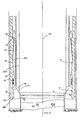
- the inner circumferential wall 26 at a lower end 28 of the drive sub 18 is provided with seating means 30 for seating the bit segments 22.
- the seating means 30 includes a land 32 extending circumferentially about the inner surface 26 followed, in the downstream direction, with a series of tapered and flat surfaces and recess 58 formed on the lowermost one of those surfaces.
- the land 32 is followed by the following sequence of surfaces in the down stream direction: surface 34 tapering away from a central longitudinal axis 36 of the drive sub 18; surface 38 extending parallel with axis 36; surface 40 tapering toward axis 36; surface 42 tapering away from axis 36; surface 44 extending parallel to axis 36; surface 46 tapering toward axis 36; and surface 48 tapering away from axis 36 and extending to the longitudinal extremity 50 of the drive sub 18.
- Contiguous with surface 48 is a surface 52 tapering away from both axis 36 and extremity 50 and which leads to outer circumferential surface 54 of the drive sub 18.
- a plurality of drive lugs 56 are provided on surface 46. Adjacent drive lugs 56 define the recesses 58 in which a lower end of the bit segments 22 are held during drilling. As is most evident from Figure 6b, the width of the drive lugs 56 reduces in the radial direction toward axis 36.
- a pair of opposed slots 60 extending parallel to axis 36 are machined in wall 26 inboard of the ends of the drive sub 18.
- a locking clip 62 (refer Figures 8a and 8b) is inserted into an upper end 64 of each slot 60.
- a lower end of each locking clip is formed with a surface 65 tapering toward the inner wall 26 and a spring clip 66 attached near an upper end of the clip on a surface opposite the inner wall 26.
- bit segments 22 are configured for mating with the seating means 30 of the drive sub 18.
- the bit segments comprise a shank 68 and a crown 70 formed at a lower end of the shank 68 for engaging and cutting the ground.
- the crown 70 typically comprises a matrix of diamonds and metal. In use, as ground engaging face 72 of the crown wears away fresh diamonds are exposed to facilitate cutting.
- Side 74 (shown uppermost in Figure 7b) of the bit segments 22 faces the inner surface 26 of the drive sub 18.
- the side 74 of shank 68 comprises the following sequence of surfaces starting from crown 70 (the axis 36 is shown in phantom for convenient reference in Figure 7a); surface 76 tapering toward axis 36; surface 77 extending parallel to axis 36; surface 78 tapering away from axis 36; surface 80 tapering toward axis 36; level surface 82 extending parallel to axis 36; surface 84 tapering away from axis 36; surface 86 tapering toward axis 36; surface 80 extending parallel to axis 36.
- Surface 88 is followed by an abrupt step 90 which leads to surface 92 tapering toward axis 36 and extending to extremity 94 of the shank 68.
- Opposite side 96 of shank 68 comprises the following sequence of surfaces in the direction from extremity 94 to crown 70: surface 98 tapering toward axis 36; level surface 100 extending parallel to axis 36; surface 102 tapering toward axis 36; and level surface 104 extending parallel to axis 36.
- the crown 70 is in the shape of a sector of an annulus and formed with inner and outer arcuate faces 106 and 108 respectively, with the length of face 108 being greater than that of face 106.
- the face of the crown 70 opposite cutting face 72 is provided with the following sequence of surfaces in the direction from outer face 108 to outer face 106: surface 110 extending parallel to cutting face 72; surface 112 inclined toward cutting face 72 and terminating adjacent surface 76 of shank 68; and surface 114 tapering away from cutting face 72 and terminating at arcuate face 106.
- Surfaces 112 and 76 form a V-shaped recess 116 which can engage the services 48 and 52 of the drive sub 18 (as seen in Figure 10).
- the tool 20 comprises a main body portion 118 upon which a selector sleeve 120 is slidably and rotatably retained.
- An upper end 122 of body 118 is provided with a screw thread for attaching a standard wire line adaptor 124.
- a pair of opposing longitudinal grooves (not shown) are machined in body 118 at end 122 for slidably retaining a ring 126.
- the ring is provided on its inner circumferential surface with a pair of protrusions (not shown) which ride in the grooves to allow the ring 126 to slide longitudinally of the body 118.
- a spring 128 retained between the wire line adaptor 124 and ring 126 acts to bias the ring 126 and sleeve 120 away from end 122.
- a protrusion 130 is formed on an end of ring 126 adjacent the sleeve 120 for engagement in one of the two mode selector recesses 132, 134 cut in an adjacent end of the sleeve 120.
- Body 118 is provided with an internal cavity 136 which houses a pair of installation latch dogs 138.
- Pin 140 extends through one end of both latch dogs 138 and couples the body 118 to the sleeve 120.
- the pin 140 resides in a longitudinal slot (not shown) formed in the body 118 and a transversely extending slot 142 formed in the sleeve 120.
- Each end of pin 140 sits on a lip 143 formed about the periphery of slots 142. This provides a connection between body 118 and sleeve 120 where the sleeve can slide longitudinally and rotate relative to the body 118.
- a second pin 144 extends parallel to pin 140 and resides in a longitudinal slot 148 formed in the body 118.
- Spring 150 connects opposite ends of latch dogs 138 to the pin 144. The spring 150 biases the latch dogs 138 so as to extend laterally of body 118 and through apertures or slots 139 (refer Figs. 4A, 4D) cut in sleeve 120.
- Each latch dog 138 is provided with a bearing face 152 for abutment with the insert 24.
- a pair of retrieval latch dogs 154 similar to the insertion latch dogs 138 is also provided in the tool 20 on a side of the latch dogs 138 opposite end 122.
- the retrieval latch dogs 154 are located in a plane disposed perpendicular to that containing the insertion latch dogs 138.
- the retrieval latch dogs are orientated in an opposite sense to the insertion latch dogs 138. That is, ends 156 of retrieval latch dogs 154 are biased by a spring (not shown) to extend laterally of the body 118 and through apertures or slots 155 (refer Figures 4a, 4e) cut in sleeve 120 with opposite ends 158 being held by a pin 160 extending through the body 118.
- Bearing faces 162 are formed at ends 156 of the retrieval latch dogs 154 for engaging the insert 24.
- the installation latch dog slots 139 are wider than the retrieval latch dog slots 155.
- a rectangular cavity 164 is formed in the body 118 adjacent the retrieval latch dogs 154. Extending longitudinally of one end 166 of the cavity 164 is a hole 168 which communicates with cylindrical recess 170. Recess 170 extends through a frusto-conical shaped end 172 of the body 118. The cavity 164, hole 168 and recess 170 collectively form a slideway 174 for a cradle 176 upon which the bit segments 22 are attained.
- the cradle 176 comprises a central bar 178 from which coaxially extends at one end a threaded stem 180 and terminates at an opposite end in a stop 182.
- the stem 180 extends through recess 170 and hole 168 into cavity 164.
- the end of the bar 178 adjacent the stem 168 is slidably received in recess 170.
- a spring 184 is retained on the stem 180 between a tension adjustment nut 186 screwed onto the stem 180 and end 166 of the cavity 164.
- Opposite ends 188 and 190 of the nut 186, are tapered or bevelled so as to reduce in thickness radially away from the centre of the nut 168.
- a pair of locking pins reside in respective recesses 192 formed in the body 118.
- the pins are retained within their respective recesses 192 by the sleeve 120 and have an end which can be selectively extended into and retracted from the recess 164 by virtue of relative movement of the sleeve 120.
- an inner circumferential wall 194 of the sleeve 120 is provided with a circumferential groove 196.
- the ends of the pins are held to extend into the cavity 164 by abutment of the pins with wall 194 when the sleeve 120 is positioned so that the groove 196 does not overlie the recesses 192. Under this condition, the pins abut against nut 186 maintaining the spring 184 in compression.
- each bit segment 22 When loading the tool 20 to install the bit segments 22, the segments are disposed radially about the bar 178 with crowns 70 abuting the stop 182. Surface 98 of each bit segment 22 rests on the large diameter end of frusto-conical end 172 for the body 118. An elastic band 198 encircles the bit segments 22 about respective surfaces 82 to hold the bit segments onto the cradle 176.
- a plurality of ridges 200 are provided on the outside surface of sleeve 120 extending parallel to the length of the sleeve 120.
- the ridges 200 are evenly spaced, with adjacent ridges defining shallow channels 202 through which a fluid can flow when the tool 20 is lowered through the drill 12.
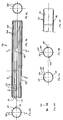
- Insert 24 (refer Figs. 5a-5c) is provided in the system 10 for expanding the bit segments 22 against the bias of elastic band 198 and locating the bit segments 22 into a cutting or drilling position against the inner surface of drive sub 18.
- the insert 24 is in the form of a cylindrical tube having a pair of opposing peaks 206 extending from an upstream end 204. The sides of each peak slope sharply in the downstream direction and lead to flats 208 which separate the peaks 206.
- a pair of longitudinally extending rails 210 protrude from the outer circumferential surface 212 of insert 24. The rails 210 ride in the slots 60 in the drive sub 18.
- a pair of opposed detents in the form of longitudinally extending slots 214 (only one shown) are cut into the insert 24 for engaging the retrieval latch dogs 154.
- An upstream end of each slot 214 is bevelled so as to slope toward an inner surface of the insert 214 in the upstream direction.
- the end of the sleeve 24 opposite peaks 206 is provided with a plurality of longitudinally extending keyways 218. Adjacent keyways 218 are spaced apart by lugs 220. Waterways 222 are machined along the length of the inner surface of insert 24. The waterways provide a flow path for water used in bit cooling, lubrication and flushing.
- a tool 20' for replacing reamer segments (refer Figs. 13 and 14) is structurally and functionally equivalent to the tool 20 used for replacement of drill bit segments 22. Accordingly, the reference numbers used in relation to the description of the tool 20 are also employed to denote similar features in the tool 20'.
- a wireline adaptor 124' is screwed onto upper end 122 of the tool 20'.
- Spring 128' interposes the wireline adaptor 124' and ring 126'.
- the ring 126' is able to slide longitudinally of the tool 20' as provided with a protrusion 130 for engaging recesses (not shown) cut in an upper end of sleeve 120'.
- Installation and retrieval latch dogs 138' and 154' are identical to those of tool 20.
- the essential differences between tool 20' and tool 20 are that the cradle 176' comprises a plurality of cut-outs 227 formed radially about a lower end of body 118'. An upper end of each cut-out is provided with a ramp 228 which leads to the outer surface of body 118'.
- sleeve 120' is provided with a plurality of apertures 230 which overlie the cut-outs 227.
- a radially inwardly directed lip 232 is provided at the lower end of each aperture 230.
- a further difference between tools 20 and 224 is the length of the slots in which the pins of the installation and retrieval latch dogs are retained. Specifically, the slots in tool 20' (see for example slot 148') are much longer than those of the corresponding slots in tool 20.
- a standard overshot attachment 234 is connected to the lower end of tool 224 for connection with the wireline adaptor 124 of tool 20. This connection allows the tools 20 and 20' to rotate relative to each other.
- Reamer segments 226 are retained in cut-outs 227 when being installed in or retrieved from the drill 12.
- Reamer segments 226 are in the shape of a rectangular prism having inclined sides.
- Each segment 226 is mounted on a rectangular plate 236.
- Upstanding lips 238 and 240 extend across the upstream and downstream ends of the plate 326 respectively. Both lip 240 and the upstream end of the plate 236 are bevelled so as to converge toward each other in the upstream direction.
- the segments 226 are retained in cut-outs 227 by rubber bands 242 and 244 which encircle plates 236 adjacent the ends of the corresponding segments 226.
- a tubular member in the form of an auxiliary drive sub 18' is screwed onto the drill for holding the reamer segments 226 in a cutting position.
- Auxiliary drive sub 18' is provided with seating means comprising a land 32' protruding inwardly from an inner circumferential wall of drive sub 18' and cut-outs 246 (only one shown) having bevelled edges 248 for seating the bit segments 226.
- a recess 250 is cut into the inner surface of the drive sub 18 adjacent the downstream end of each cut-out 246 for accommodating the lips 238.
- Auxiliary insert 24' is retained with auxiliary drive sub 18 for selectively holding the segments 226 in a cutting position and releasing the segments 226 for replacement.
- Insert 24' is essentially the same as insert 24 with the exception that it does not include the keyways 218 and lugs 220 of insert 24.
- Tool 20' is used to slide the insert 24' between an installation position in which the insert 24' locates and retains the segments 226 in the cutting position and, a retrieval position in which the insert 24' is retracted to release the segments so that they can collapse back onto the tool 226 by action of the elastic bands 242 and 244.
- the ground drill 12 is in this embodiment a core sampling drill such as for example, of the type manufactured by LONGYEAR.
- Core sampling drills typically include a landing ring 252 retained in a lower end of the drill 12.
- the landing ring 252 is used to halt the passage of a conventional core sample barrel 254 (refer Figures 10 and 11).
- the top of the core sample barrel 254 rests on the landing ring 252 preventing the core sample barrel 254 from falling out of the drill 12.
- the core sample barrel 254 is used to collect and retain a core sample of the ground being drilled. Once the core sample barrel is filled, drilling is stopped, the drill lifted from the bottom of the hole being drilled to break the core sample, then the core sample barrel lifted up through the drill 12 by a wire line 256.
- the drive sub 18 is screwed onto the reamer 16 of a standard core sampling drill.
- Tool 20 is set to the installation mode by turning sleeve 120 relative to ring 126 so that the protrusion 130 engages installation mode selector recess 132.
- Cradle 176 is extended from body 118 compressing the spring 184 which is held in compression by locking pins (not shown) having ends extending into the cavity 164.
- the installation latch dogs 138 extend laterally from slots 139 in the sleeve 120.
- the retrieval latch dogs 154 are not aligned with slots 155 and are therefore held in a compressed state within the confines of sleeve 120.
- Bit segments 22 are loaded onto the cradle 176 and held in place by elastic band 198 which contacts the surface 82 of each bit segment 22. Crown 70 of each bit segment abuts stop 182.
- the insert 24 is disposed within the drive sub 18 and held above the seating means 30 by clip 62. The insert 24 is orientated so that peaks 206 point in the upstream direction. Rails 210 of the insert 24 ride in slots 60 to allow the insert 24 to slide along the inside of the drive sub 18.
- Tool 20 is connected to a standard wire line overshot via the wireline adaptor 124 and inserted into transport sleeve 260 (shown in Figure 15) which compresses the installation latch dogs 138.
- Transport sleeve 260 together with tool 20 is then lowered through the centre of the drill 12.
- Transport sleeve dead weight 262 (refer Figure 16) can be attached to an upper end of sleeve 260 to increase the rate of decent of tool 20.
- the decent of the transport sleeve 260 is halted by abutment with the landing ring 252.
- the tool 20 which has an outer diameter smaller than the inner diameter of the ring 252 continues its decent.
- the installation latch dogs 138 are biased by spring 150 to extend from slots 139 formed in sleeve 120.
- Bearing faces 152 of latch dogs 138 contact peaks 206 causing the tool 20 to rotate until a position is reached where the bearing faces 152 reside on flats 208 separating the peaks 206.
- the rotation of the tool 20 ensures correct alignment of bit segments 22 with recesses 56 of the drive sub 18 and keyways 218 of the insert 24.
- the latch dogs 138 are driven backward a short distance upon impacting with peaks 206 causing a corresponding movement in the sleeve 120. This action results in the groove 196 being located over recesses 192 so that the pins (not shown) residing therein are retracted from cavity 164 allowing spring 184 to expand. This in turn causes the cradle 176 to retract into the body 118. Surface 98 of each bit segment slides along the frusto-conical end 172 to extend laterally of the body 118 and contact inner wall 22 (refer Figure 9). As tool 120 continues its decent, the step 90 of shanks 68 engage the land 32 on the drive sub 18.
- the continued downward movement of the tool 120 also draws insert 24 downwards by virtue of the installation latch dogs 138 bearing on flats 208.
- step 90 of each bit engages land 32 further downward movement of the bit segments 22 is prevented.
- the insert 24 collects the backside 96 of the bit segments and acts to expand the bit segments 22 outwardly in the radial direction against the bias of elastic band 198 locating the bit segments into separate recesses 58.
- the insert 24 continues to move downwardly until it reaches the installation position in which its keyways 218 slide over the bit segments 22 to retain the bit segments between the drive sub 18.
- Elastic band 198 resides in a cavity formed between surface 44 of the drive sub 18 and surface 82 of the bit segments 22.
- Tool 20 can then be withdrawn via the wireline 256 to the landing ring 252 upon which, installation latch dogs 138 are compressed by being drawn backwards through ring 252. Tool 20 then re-enters the transport sleeve 260 and both are completely withdrawn from the drill 12.
- Standard core sample barrel 254 can then be lowered into the drill 12 via wire line 256 for holding a core sample of the ground being drilled.
- Insert 24 is dimensioned to allow the core sample barrel 254 (refer Figs. 10 and 11) to pass therethrough.
- bit segments 22 With the bit segments 22 retained between drive sub 18 and insert 24 so as to form a drill bit, the drill 12 is lowered to the bottom of the bore hole being drilled and rotated to recommence drilling.
- bit segments 22 are forced to slide backward with surfaces 34, 48 and 52 of the drive sub bearing against surfaces 86, 112, and 114 of the bit segments respectively.
- steps 90 are spaced above the land 32. The sliding motion of the bit segments is facilitated by surfaces 77 and 88 of the bit segments, and surface 38 of the drive sub, all of which extend parallel to axis 36.
- the arrangement of surfaces on the bit segments 22 and drive sub 18 transfers the bit weight and internal/external rotational forces created during drilling to the drive sub 18. Furthermore, this action locks the insert 24 in place by means of a clamping action as the uppermost inside edge of each bit segment is forced slightly inwardly, against the outer circumferential wall 212 of the insert 24.
- bit segments slide relative to the drive sub 18 until steps 90 abut land 32, with surfaces 40 and 46 of the drive sub bearing against surfaces 84 and 78 of the bit segments respectively.
- the core sample barrel 254 also exerts a force against surface 102 of the bit segments 22. This force is transmitted in a diagonal direction inclined toward the bottom of the bore hole from the bit segments 22 to the drive sub 18 between respective surface pairs 77 and 46; and, 84 and 40 as shown by arrows D, E and G.
- a space or gap between surfaces 78 and 46 on the bit segments 22 and drive sub 18 respectively allows the bit segments 22 to flex radially outwardly when the core sample barrel 254 exerts a force on the bit segments 22 during core breaking. This spreads the bit segments radially away from axis 36 during core breaking and allows the core sample to be broken from the rock formation being drilled in the conventional manner via a core sample barrel lifter (not shown).
- the insert 24 locks the bit segments 22 in place by a clamping action as the upper most inside edge of each bit segment is forced slightly inwardly against the outer circumferential wall 212 of insert 24.
- Rotational drive is rotated from the drive sub 18 to the bit segments 22 via drive lugs 56.
- Bit lubrication and cooling is provided in the conventional manner with fluid being pumped into the drill 12 and channelled via internal waterways 222 of insert 24 which allows the fluid to reach the bit crown 70.
- cooling at the bit crown 70 is substantially different to that achieved with standard drill bits.
- Extremely wide waterways are automatically provided in the present system 10 by the gaps formed between adjacent bit segments 22.
- the drill 12 is initially lifted a short distance off the bottom of the hole so as to break a core sample from rock formation 264.
- the core sample barrel 254 is then removed from the drill by use of wireline 256 in the conventional manner.
- Tool 20 is placed into the retrieval mode by means of a counter-twist of sleeve 120 so that the retrieval recess 134 engages protrusion 130. This results in slots 155 being aligned with the retrieval latch dogs 154 which become fully expanded and extend beyond the surface of sleeve 120.
- the tool 20 is inserted into transport sleeve 260 and lowered through the drill 12. Upon reaching the landing ring 252, the decent of sleeve 260 is halted but the tool 20 continues through the landing ring 252 exposing the retrieval and installation latch dogs 138, 154 which contact inner circumferential wall of the drill 12.
- Tool 20 then enters the insert 24 and in doing so results in the retrieval latch dogs being compressed by contact with the inner circumferential wall of the insert 24.
- the installation latch dogs 138 contact peaks 206, rotating the tool into correct alignment in the drive sub 18.
- the retrieval latch dogs 154 expand into slots 214 provided in the insert 24.
- Cradle 176 is in an extended position with spring 184 compressed and nut 186 locked against linear movement by the locking pins (not shown) residing in recesses 192.
- Cradle 176 is disposed centrally of the bit segments 22 with stop 182 extending beyond the bit crowns 70.
- the retrieval latch dogs 154 draw back the insert 24 which slides along slots 60 in drive sub 18. Simultaneously, the bit segments 22 are released and collapse onto cradle 176 by contraction of the elastic bands 198. Upon further upward pulling of the tool 20 the retrieval latch dogs 154 are disengaged automatically from insert 24 by being compressed by tapered surfaces 65 on the clip 62.
- both the retrieval latch dogs and installation latch dogs contact the inner circumferential wall of the drill 12.
- the installation latch dogs are compressed against the bias of spring 150 so as to pass through ring 252.
- the faces 162 together with the lower end face of landing ring 252 are provided with bevelled or tapers so that an abutment of the retrieval latch dogs with the landing ring, the application of an upward force will result in the retrieval latch dogs being compressed so as to pass through the landing ring 252.
- the tool 20 then re-enters the transport sleeve 260 and together therewith is pulled to the surface.
- the bit segments 22 can then be removed from the cradle 176 and new drill bits can be attached hereto for installation on the drive sub 18.
- the standard reamer 16 is replaced with drive sub 18'.
- the reamer segments 226 typically would be changed simultaneously with drill bit segments 22 by connecting the wireline overshot 234 of tool 20' with the wireline adaptor 124 of tool 20. This allows relative rotation of tools 20 and 20'. While reamer segment and bit segment replacement would occur simultaneously, the reamer segments would not be replaced as often as the bit segments.
- tool 20' is left in the installation mode and no reamer segments 226 are loaded onto the cradle 176'.
- the present invention enjoys numerous advantages and benefits over the prior art. Most importantly, it allows easy and very quick replacement of the drill bit and reamer without the need to withdraw the string from the hole, thereby reducing downtime, increasing productivity, and reducing drilling costs.
- the ease and simplicity of changing the drill bit also encourages the changing of drill bits in conjunction with variations in sub-strata in order to optimise bit hardness and characteristics with the sub-strata encountered.
- the unique shape and configuration of the drill bits in conjunction with the keyways of the drive sub and configuration of the insert performs the following major functions:
Abstract
Description
- This invention relates to a system for in situ replacement of cutting means for a ground drill, and in particular, to an insert for use in the in situ replacement of drill bits and/or reamers of core sampling drills.
- In ground drilling it is customary to detachably fix a drill bit to a lower end of a drill string of a ground drill and rotate the drill string to effect drilling of a hole in the ground by the drill bit. A reamer is usually connected between the lower end of the drill string and the drill bit to ream the circumferential wall of a hole being drilled. The drill string is formed by screwing individual drill rods together. Drill rods usually come in fixed lengths of 1.5, 3 or 6 metres. As the drill progresses into the ground additional drill rods are screwed into the upper end drill string.
- During drilling it will be necessary to replace the drill bit and reamer either as a result of dulling of the drill bit or due to variations in the sub strata. Although the drill bit must be replaced more often (usually at least six times more often) than the reamer.
- In order to replace a drill bit or reamer the entire drill string must be pulled out of the ground rod by rod, the drill bit replaced, and the drill string reassembled, rod by rod as it is relowered into the ground to continue drilling. The need to fully withdraw, disassemble and reassemble the drill string when changing the drill bit/reamer is a slow and costly exercise, with the cost increasing as hole depth increases and the drill string becomes longer.
- Several attempts have previously been made to overcome this problem at least in so far as drill bits are concerned by use of retractable drill bits which releasably engage the lower end of the drill string and can be disengaged and retracted through the drill string for changing while the drill string remains in situ, thereby avoiding the need to withdraw the drill string from the hole. However, these attempts have not proven to be commercially successful for various reasons including: being extremely complicated in design or application thereby resulting in a large number of failure modes and/or being to costly to manufacture or maintain in an operational state; being prone to fouling due to drilling fluid and contaminants burring or jamming segments of the drill bit; misalignment of drill bit segments upon engagement with the drill string; reduction in diameter of the core sample due to fixing of the drill bit to an inner tube of the drill string; reduction in penetration rate; and breaking of individual segments of the drill bit.
- It is an object of the present invention to provide an insert for use in a system for in situ replacement of drill bits and/or reamers of a ground drill which attempts to overcome at least one of the above-described deficiencies in the prior art.
- According to the present invention there is provided an insert for releasably retaining cutting means in a ground drill, said insert comprising a substantially cylindrical member movable within said ground drill between an installation position in which said insert retains said cutting means in a cutting position between an outer circumferential surface of said insert and an inner circumferential surface of said ground drill, and a retrieval position in which said insert is retracted to release said cutting means from between said outer circumferential surface of said insert and said inner circumferential surface of said ground drill.
- Preferably, said insert further comprises a plurality of radially spaced and longitudinally extending keyways formed about said outer circumferential wall and at a lower end of said member for receiving said cutting means in retaining said cutting means and said cutting position.
- Preferably, an upper end of said insert is profiled to cause rotation of said cutting means about a longitudinal axis of said drill when said cutting means is being installed in said ground drill to thereby align said cutting means with said keyways.
- Preferably, said upper end of said insert is provided with two opposing peaks adapted to contact a tool used for transporting said cutting means to and from said ground drill, whereby, in use, when said tool abuts said peaks, said tool can be rotated about the longitudinal axis of said drill to thereby align said cutting means with said keyways.
- Preferably, said insert further comprises guiding means for guiding said insert to move in a longitudinal direction between said installation position and said retrieval position.
- Preferably, said guiding means comprises a rail or a channel formed on said outer circumferential surface of said insert adapted for engaging a channel or a rail, respectively formed on said inner circumferential surface of said ground drill.
- Preferably, said insert further comprises a plurality of longitudinally extending channels from in an inner circumferential surface of said insert to provide a flow path for fluid used for cooling and lubricating said cutting means when said ground drill is operated to drill a hole.
- Preferably, said insert further comprises a first detent for engaging said tool when said tool is initially moved upward a first distance so as to move said insert to said retrieval position.
- Preferably, said insert further comprises disengaging means for disengaging said tool from said detent when said tool is pulled upwardly beyond said first distance.
- Preferably, said first detent is a recess cut in said cylindrical member.
- Preferably, said disengaging means comprises a tapered surface leading, in the upward direction, from said recess to an inner circumferential surface of said cylindrical member.
- Embodiments of the present invention will now be described by way of example only, with reference to the accompanying drawings in which:
- Figure 1 is a side elevation view of a first embodiment of the system disposed within a ground drill;
- Figure 2 is a side elevation view of a tool used in the system shown in Figure 1;
- Figure 3 is a longitudinal section view of the tool shown in Figure 2;
- Figure 4a is a side elevation view of a selector sleeve of the tool shown in Figures 2 and 3;
- Figure 4b is a end view of the sleeve shown in Figure 4a; Figure 4a;
- Figure 4f is a part view of Section A-A shown in Figure 4b;
- Figure 4g is a view of Section D-D shown in Figure 4a;
- Figure 5a is a side elevation view of an insert used in the system shown in Figure 1;
- Figure 5b is a view of one end of the insert shown in Figure 5a;
- Figure 5c is a view of an opposite end of the insert shown in Figure 5a;
- Figure 6a is a longitudinal section view of a member used in the system shown in Figure 1;
- Figure 6b is a view of one end of the member shown in Figure 6a;
- Figure 6c is a view of an opposite end of the member shown in Figure 6a;
- Figure 6d is a view of a lower portion of the member shown in Figure 6a;
- Figure 7a is a side view of a bit segment used in the system shown in Figure 1;
- Figure 7b is a top view of the bit segment shown in Figure 6a;
- Figure 7c is an end view of the bit segment shown in Figures 7a and 7b;
- Figure 8a is a top view of a locking clip used in the system shown in Figure 1;
- Figure 8b is a side view of the locking clip shown in Figure 6a;
- Figure 9 is an enlarged partial section view of a lower end of the system;
- Figure 10 is a sectional view of an end of the drill in a drilling mode with bit segments locked in a cutting position by the insert;
- Figure 11 is a view of the drill string shown in Figure 10 but with the drill string pulled upwardly from a bottom of a hole being drilled;
- Figure 12 is a sectional view of a tool used in a second embodiment of the present invention;
- Figure 13 is a top view of a reamer segment used in the second embodiment of the invention;
- Figure 14 is a partial sectional view of the second embodiment of the invention where the reamer segments are held in a cutting position;
- Figure 15 is a side view of a transport sleeve for the system shown in Figure 1; and,
- Figure 16 is a side view of a transport sleeve deadweight for the system shown in Figure 1.
- Figure 1 illustrates a first embodiment of a
system 10 for the in situ replacement of cutting means in the form of a drill bit of aground drill 12. Thedrill 12 is composed of a plurality of interconnecteddrill rods 14 which together form a drill string. Astandard reamer 16 for reaming the circumferential wall of a hole being drilled is screwed to the free end of thelowest rod 14. - The
system 10 comprises a number of separate but interactive components these including a tubular member taking the form of adrive sub 18 which is adapted for connection to a lower end of thedrill 12, an installation andretrieval tool 20 dimensioned to travel through thedrill 12 for carrying drill bit segments 22 (refer Figs. 7a, 7b, and 9) to and from thedrive sub 18 and, a substantiallycylindrical insert 24 which is slidably retained within themember 18 between an installation position in which the insert retains thebit segments 22 in thedrive sub 18 and a retrieval position in which theinsert 24 is retracted to allow thebit segments 22 to collapse onto thetool 20 for withdrawal from thedrill 12. - Referring to Figures 6a and 6d, it can be seen that the inner
circumferential wall 26 at alower end 28 of thedrive sub 18 is provided with seating means 30 for seating thebit segments 22. The seating means 30 includes aland 32 extending circumferentially about theinner surface 26 followed, in the downstream direction, with a series of tapered and flat surfaces andrecess 58 formed on the lowermost one of those surfaces. Specifically, theland 32 is followed by the following sequence of surfaces in the down stream direction:surface 34 tapering away from a centrallongitudinal axis 36 of thedrive sub 18;surface 38 extending parallel withaxis 36;surface 40 tapering towardaxis 36;surface 42 tapering away fromaxis 36; surface 44 extending parallel toaxis 36;surface 46 tapering towardaxis 36; andsurface 48 tapering away fromaxis 36 and extending to thelongitudinal extremity 50 of thedrive sub 18. Contiguous withsurface 48 is asurface 52 tapering away from bothaxis 36 andextremity 50 and which leads to outercircumferential surface 54 of thedrive sub 18. - A plurality of drive lugs 56 are provided on
surface 46. Adjacent drive lugs 56 define therecesses 58 in which a lower end of thebit segments 22 are held during drilling. As is most evident from Figure 6b, the width of the drive lugs 56 reduces in the radial direction towardaxis 36. A pair ofopposed slots 60 extending parallel toaxis 36 are machined inwall 26 inboard of the ends of thedrive sub 18. A locking clip 62 (refer Figures 8a and 8b) is inserted into anupper end 64 of eachslot 60. A lower end of each locking clip is formed with asurface 65 tapering toward theinner wall 26 and a spring clip 66 attached near an upper end of the clip on a surface opposite theinner wall 26. - As explained with reference to Figures 7a and 7b, the
bit segments 22 are configured for mating with the seating means 30 of thedrive sub 18. The bit segments comprise ashank 68 and acrown 70 formed at a lower end of theshank 68 for engaging and cutting the ground. Thecrown 70 typically comprises a matrix of diamonds and metal. In use, asground engaging face 72 of the crown wears away fresh diamonds are exposed to facilitate cutting. - Side 74 (shown uppermost in Figure 7b) of the
bit segments 22 faces theinner surface 26 of thedrive sub 18. Theside 74 ofshank 68 comprises the following sequence of surfaces starting from crown 70 (theaxis 36 is shown in phantom for convenient reference in Figure 7a);surface 76 tapering towardaxis 36;surface 77 extending parallel toaxis 36;surface 78 tapering away fromaxis 36;surface 80 tapering towardaxis 36;level surface 82 extending parallel toaxis 36;surface 84 tapering away fromaxis 36;surface 86 tapering towardaxis 36;surface 80 extending parallel toaxis 36.Surface 88 is followed by anabrupt step 90 which leads to surface 92 tapering towardaxis 36 and extending toextremity 94 of theshank 68. - Opposite
side 96 ofshank 68 comprises the following sequence of surfaces in the direction fromextremity 94 to crown 70:surface 98 tapering towardaxis 36;level surface 100 extending parallel toaxis 36;surface 102 tapering towardaxis 36; andlevel surface 104 extending parallel toaxis 36. - As shown most clearly in Figure 7c, the
crown 70 is in the shape of a sector of an annulus and formed with inner and outerarcuate faces face 108 being greater than that offace 106. - The face of the
crown 70 opposite cuttingface 72 is provided with the following sequence of surfaces in the direction fromouter face 108 to outer face 106:surface 110 extending parallel to cuttingface 72;surface 112 inclined toward cuttingface 72 and terminatingadjacent surface 76 ofshank 68; andsurface 114 tapering away from cuttingface 72 and terminating atarcuate face 106.Surfaces services - Referring to Figures 2-4f, the
tool 20 comprises amain body portion 118 upon which aselector sleeve 120 is slidably and rotatably retained. Anupper end 122 ofbody 118 is provided with a screw thread for attaching a standardwire line adaptor 124. A pair of opposing longitudinal grooves (not shown) are machined inbody 118 atend 122 for slidably retaining aring 126. The ring is provided on its inner circumferential surface with a pair of protrusions (not shown) which ride in the grooves to allow thering 126 to slide longitudinally of thebody 118. Aspring 128 retained between thewire line adaptor 124 and ring 126 acts to bias thering 126 andsleeve 120 away fromend 122. Aprotrusion 130 is formed on an end ofring 126 adjacent thesleeve 120 for engagement in one of the two mode selector recesses 132, 134 cut in an adjacent end of thesleeve 120. -
Body 118 is provided with aninternal cavity 136 which houses a pair of installation latch dogs 138.Pin 140 extends through one end of both latchdogs 138 and couples thebody 118 to thesleeve 120. Thepin 140 resides in a longitudinal slot (not shown) formed in thebody 118 and a transversely extendingslot 142 formed in thesleeve 120. Each end ofpin 140 sits on alip 143 formed about the periphery ofslots 142. This provides a connection betweenbody 118 andsleeve 120 where the sleeve can slide longitudinally and rotate relative to thebody 118. - A
second pin 144 extends parallel to pin 140 and resides in alongitudinal slot 148 formed in thebody 118.Spring 150 connects opposite ends oflatch dogs 138 to thepin 144. Thespring 150 biases the latch dogs 138 so as to extend laterally ofbody 118 and through apertures or slots 139 (refer Figs. 4A, 4D) cut insleeve 120. Eachlatch dog 138 is provided with abearing face 152 for abutment with theinsert 24. - A pair of
retrieval latch dogs 154 similar to the insertion latch dogs 138 is also provided in thetool 20 on a side of the latch dogs 138opposite end 122. However, theretrieval latch dogs 154 are located in a plane disposed perpendicular to that containing the insertion latch dogs 138. In addition, the retrieval latch dogs are orientated in an opposite sense to the insertion latch dogs 138. That is, ends 156 ofretrieval latch dogs 154 are biased by a spring (not shown) to extend laterally of thebody 118 and through apertures or slots 155 (refer Figures 4a, 4e) cut insleeve 120 withopposite ends 158 being held by apin 160 extending through thebody 118. Bearing faces 162 are formed at ends 156 of theretrieval latch dogs 154 for engaging theinsert 24. - As is most evident from Figures 4d and 4e, the installation
latch dog slots 139 are wider than the retrievallatch dog slots 155. - A
rectangular cavity 164 is formed in thebody 118 adjacent the retrieval latch dogs 154. Extending longitudinally of oneend 166 of thecavity 164 is a hole 168 which communicates withcylindrical recess 170.Recess 170 extends through a frusto-conicalshaped end 172 of thebody 118. Thecavity 164, hole 168 andrecess 170 collectively form aslideway 174 for acradle 176 upon which thebit segments 22 are attained. - The
cradle 176 comprises acentral bar 178 from which coaxially extends at one end a threadedstem 180 and terminates at an opposite end in astop 182. Thestem 180 extends throughrecess 170 and hole 168 intocavity 164. The end of thebar 178 adjacent the stem 168 is slidably received inrecess 170. A spring 184 is retained on thestem 180 between atension adjustment nut 186 screwed onto thestem 180 and end 166 of thecavity 164. Opposite ends 188 and 190 of thenut 186, are tapered or bevelled so as to reduce in thickness radially away from the centre of the nut 168. - A pair of locking pins (not shown) reside in
respective recesses 192 formed in thebody 118. The pins are retained within theirrespective recesses 192 by thesleeve 120 and have an end which can be selectively extended into and retracted from therecess 164 by virtue of relative movement of thesleeve 120. Referring to Figure 4f, an innercircumferential wall 194 of thesleeve 120 is provided with acircumferential groove 196. When thesleeve 20 is positioned so that thegroove 196 overlies therecesses 192, the ends of the pins therein can be retracted from thecavity 164 to allow extension of spring 184. However, the ends of the pins are held to extend into thecavity 164 by abutment of the pins withwall 194 when thesleeve 120 is positioned so that thegroove 196 does not overlie therecesses 192. Under this condition, the pins abut againstnut 186 maintaining the spring 184 in compression. - When loading the
tool 20 to install thebit segments 22, the segments are disposed radially about thebar 178 withcrowns 70 abuting thestop 182.Surface 98 of eachbit segment 22 rests on the large diameter end of frusto-conical end 172 for thebody 118. Anelastic band 198 encircles thebit segments 22 aboutrespective surfaces 82 to hold the bit segments onto thecradle 176. - A plurality of
ridges 200 are provided on the outside surface ofsleeve 120 extending parallel to the length of thesleeve 120. Theridges 200 are evenly spaced, with adjacent ridges definingshallow channels 202 through which a fluid can flow when thetool 20 is lowered through thedrill 12. - Insert 24 (refer Figs. 5a-5c) is provided in the
system 10 for expanding thebit segments 22 against the bias ofelastic band 198 and locating thebit segments 22 into a cutting or drilling position against the inner surface ofdrive sub 18. - The
insert 24 is in the form of a cylindrical tube having a pair of opposingpeaks 206 extending from anupstream end 204. The sides of each peak slope sharply in the downstream direction and lead toflats 208 which separate thepeaks 206. A pair of longitudinally extendingrails 210 protrude from the outercircumferential surface 212 ofinsert 24. Therails 210 ride in theslots 60 in thedrive sub 18. A pair of opposed detents in the form of longitudinally extending slots 214 (only one shown) are cut into theinsert 24 for engaging the retrieval latch dogs 154. An upstream end of eachslot 214 is bevelled so as to slope toward an inner surface of theinsert 214 in the upstream direction. The end of thesleeve 24opposite peaks 206 is provided with a plurality of longitudinally extendingkeyways 218.Adjacent keyways 218 are spaced apart bylugs 220.Waterways 222 are machined along the length of the inner surface ofinsert 24. The waterways provide a flow path for water used in bit cooling, lubrication and flushing. - A tool 20' (refer Figure 12) for replacing reamer segments (refer Figs. 13 and 14) is structurally and functionally equivalent to the
tool 20 used for replacement ofdrill bit segments 22. Accordingly, the reference numbers used in relation to the description of thetool 20 are also employed to denote similar features in the tool 20'. A wireline adaptor 124' is screwed ontoupper end 122 of the tool 20'. Spring 128' interposes the wireline adaptor 124' and ring 126'. As withtool 20, the ring 126' is able to slide longitudinally of the tool 20' as provided with aprotrusion 130 for engaging recesses (not shown) cut in an upper end of sleeve 120'. Installation and retrieval latch dogs 138' and 154' are identical to those oftool 20. The essential differences between tool 20' andtool 20 are that the cradle 176' comprises a plurality of cut-outs 227 formed radially about a lower end of body 118'. An upper end of each cut-out is provided with aramp 228 which leads to the outer surface of body 118'. In addition, sleeve 120' is provided with a plurality ofapertures 230 which overlie the cut-outs 227. A radially inwardly directedlip 232 is provided at the lower end of eachaperture 230. - A further difference between
tools 20 and 224 is the length of the slots in which the pins of the installation and retrieval latch dogs are retained. Specifically, the slots in tool 20' (see for example slot 148') are much longer than those of the corresponding slots intool 20. - A standard overshot
attachment 234 is connected to the lower end of tool 224 for connection with thewireline adaptor 124 oftool 20. This connection allows thetools 20 and 20' to rotate relative to each other. -
Reamer segments 226 are retained in cut-outs 227 when being installed in or retrieved from thedrill 12.Reamer segments 226 are in the shape of a rectangular prism having inclined sides. Eachsegment 226 is mounted on arectangular plate 236.Upstanding lips lip 240 and the upstream end of theplate 236 are bevelled so as to converge toward each other in the upstream direction. - The
segments 226 are retained in cut-outs 227 byrubber bands plates 236 adjacent the ends of the correspondingsegments 226. - A tubular member in the form of an auxiliary drive sub 18' is screwed onto the drill for holding the
reamer segments 226 in a cutting position. Auxiliary drive sub 18' is provided with seating means comprising a land 32' protruding inwardly from an inner circumferential wall of drive sub 18' and cut-outs 246 (only one shown) having bevellededges 248 for seating thebit segments 226. Arecess 250 is cut into the inner surface of thedrive sub 18 adjacent the downstream end of each cut-out 246 for accommodating thelips 238. - Auxiliary insert 24' is retained with
auxiliary drive sub 18 for selectively holding thesegments 226 in a cutting position and releasing thesegments 226 for replacement. Insert 24' is essentially the same asinsert 24 with the exception that it does not include thekeyways 218 and lugs 220 ofinsert 24. Tool 20' is used to slide the insert 24' between an installation position in which the insert 24' locates and retains thesegments 226 in the cutting position and, a retrieval position in which the insert 24' is retracted to release the segments so that they can collapse back onto thetool 226 by action of theelastic bands - Referring again to Figure 1, the
ground drill 12 is in this embodiment a core sampling drill such as for example, of the type manufactured by LONGYEAR. Core sampling drills typically include alanding ring 252 retained in a lower end of thedrill 12. Thelanding ring 252 is used to halt the passage of a conventional core sample barrel 254 (refer Figures 10 and 11). The top of thecore sample barrel 254 rests on thelanding ring 252 preventing thecore sample barrel 254 from falling out of thedrill 12. Thecore sample barrel 254 is used to collect and retain a core sample of the ground being drilled. Once the core sample barrel is filled, drilling is stopped, the drill lifted from the bottom of the hole being drilled to break the core sample, then the core sample barrel lifted up through thedrill 12 by awire line 256. - When the
system 10 is used for in situ replacement of a drill bit only, then the conventional core sampling drill bit (not shown) is replaced withdrive sub 18 which threadingly engagesreamer 16. In the event that thesystem 10 is also to be used to allow in situ replacement of the reamer, then thestandard reamer 16 is also removed and replaced with drive sub 18'.Inserts 24 and/or 24' are always retained within correspondingdrive subs 18 and 18'.Tools 20 and 20' are lowered and retrieved from thedrill 12 for installing and retrievingbit segments tools 20 and 20' are removed, standardcore sample barrel 254 can then be lowered into thedrill 12 which passes through theinserts 24 and 24' for receiving a core sample. The method of operation of thesystem 10 will now be described in connection with the replacement of drill bit segments. - The
drive sub 18 is screwed onto thereamer 16 of a standard core sampling drill.Tool 20 is set to the installation mode by turningsleeve 120 relative to ring 126 so that theprotrusion 130 engages installationmode selector recess 132.Cradle 176 is extended frombody 118 compressing the spring 184 which is held in compression by locking pins (not shown) having ends extending into thecavity 164. In this configuration, theinstallation latch dogs 138 extend laterally fromslots 139 in thesleeve 120. However, theretrieval latch dogs 154 are not aligned withslots 155 and are therefore held in a compressed state within the confines ofsleeve 120.Bit segments 22 are loaded onto thecradle 176 and held in place byelastic band 198 which contacts thesurface 82 of eachbit segment 22.Crown 70 of each bit segment abuts stop 182. Theinsert 24 is disposed within thedrive sub 18 and held above the seating means 30 byclip 62. Theinsert 24 is orientated so thatpeaks 206 point in the upstream direction.Rails 210 of theinsert 24 ride inslots 60 to allow theinsert 24 to slide along the inside of thedrive sub 18. -
Tool 20 is connected to a standard wire line overshot via thewireline adaptor 124 and inserted into transport sleeve 260 (shown in Figure 15) which compresses the installation latch dogs 138.Transport sleeve 260 together withtool 20 is then lowered through the centre of thedrill 12. Transport sleeve dead weight 262 (refer Figure 16) can be attached to an upper end ofsleeve 260 to increase the rate of decent oftool 20. The decent of thetransport sleeve 260 is halted by abutment with thelanding ring 252. However, thetool 20 which has an outer diameter smaller than the inner diameter of thering 252 continues its decent. As thetool 20 passes throughlanding ring 252, theinstallation latch dogs 138 are biased byspring 150 to extend fromslots 139 formed insleeve 120. Bearing faces 152 oflatch dogs 138contact peaks 206 causing thetool 20 to rotate until a position is reached where the bearing faces 152 reside onflats 208 separating thepeaks 206. The rotation of thetool 20 ensures correct alignment ofbit segments 22 withrecesses 56 of thedrive sub 18 andkeyways 218 of theinsert 24. - The latch dogs 138 are driven backward a short distance upon impacting with
peaks 206 causing a corresponding movement in thesleeve 120. This action results in thegroove 196 being located overrecesses 192 so that the pins (not shown) residing therein are retracted fromcavity 164 allowing spring 184 to expand. This in turn causes thecradle 176 to retract into thebody 118.Surface 98 of each bit segment slides along the frusto-conical end 172 to extend laterally of thebody 118 and contact inner wall 22 (refer Figure 9). Astool 120 continues its decent, thestep 90 ofshanks 68 engage theland 32 on thedrive sub 18. - The continued downward movement of the
tool 120 also drawsinsert 24 downwards by virtue of theinstallation latch dogs 138 bearing onflats 208. Whenstep 90 of each bit engagesland 32 further downward movement of thebit segments 22 is prevented. Theinsert 24 collects thebackside 96 of the bit segments and acts to expand thebit segments 22 outwardly in the radial direction against the bias ofelastic band 198 locating the bit segments intoseparate recesses 58. Theinsert 24 continues to move downwardly until it reaches the installation position in which itskeyways 218 slide over thebit segments 22 to retain the bit segments between thedrive sub 18.Elastic band 198 resides in a cavity formed between surface 44 of thedrive sub 18 andsurface 82 of thebit segments 22. -
Tool 20 can then be withdrawn via thewireline 256 to thelanding ring 252 upon which,installation latch dogs 138 are compressed by being drawn backwards throughring 252.Tool 20 then re-enters thetransport sleeve 260 and both are completely withdrawn from thedrill 12. - The
bit segments 22 locked about thedrive sub 18 form a drill bit for cutting the ground. Standardcore sample barrel 254 can then be lowered into thedrill 12 viawire line 256 for holding a core sample of the ground being drilled.Insert 24 is dimensioned to allow the core sample barrel 254 (refer Figs. 10 and 11) to pass therethrough. - With the
bit segments 22 retained betweendrive sub 18 and insert 24 so as to form a drill bit, thedrill 12 is lowered to the bottom of the bore hole being drilled and rotated to recommence drilling. Referring to Figure 10 as the bit crowns 70 touch the bottom of the hole,bit segments 22 are forced to slide backward withsurfaces surfaces land 32. The sliding motion of the bit segments is facilitated bysurfaces axis 36. - The arrangement of surfaces on the
bit segments 22 and drivesub 18 transfers the bit weight and internal/external rotational forces created during drilling to thedrive sub 18. Furthermore, this action locks theinsert 24 in place by means of a clamping action as the uppermost inside edge of each bit segment is forced slightly inwardly, against the outercircumferential wall 212 of theinsert 24. - The transfer of forces during drilling between the
bit segments 22 and drivesub 18 are also shown in Figure 10 and are described hereinafter. Arrow A shows the direction of transference of a portion of the string weight from thebit crown 70 to thedrive sub 18 during drilling. This force is directed in the longitudinal direction ofdrive sub 18 and is applied tosurfaces surface 86 of each bit segment to surface 34 of each keyway as shown by Arrow F in Figure 10. This force also causes thebit segments 22 to move radially inwards so as to provide the clamping action againstinsert 24 required during drilling. - External radial forces acting on
face 108 ofcrowns 70 transferred to the drive sub bysurface 52 as shown by arrow B. These forces are also borne bysurfaces drive sub 18. Internal radial forces on thebit crown 70 and drive lugs 56 are transferred to the drive sub viasurface 48 as indicated by arrow C. - During core breaking (shown in Figure 11) when the
drill 12 is lifted from the bottom of the borehole, the bit segments slide relative to thedrive sub 18 untilsteps 90abut land 32, withsurfaces surfaces core sample barrel 254 also exerts a force againstsurface 102 of thebit segments 22. This force is transmitted in a diagonal direction inclined toward the bottom of the bore hole from thebit segments 22 to thedrive sub 18 between respective surface pairs 77 and 46; and, 84 and 40 as shown by arrows D, E and G. - A space or gap between
surfaces bit segments 22 and drivesub 18 respectively (shown in Figure 10) allows thebit segments 22 to flex radially outwardly when thecore sample barrel 254 exerts a force on thebit segments 22 during core breaking. This spreads the bit segments radially away fromaxis 36 during core breaking and allows the core sample to be broken from the rock formation being drilled in the conventional manner via a core sample barrel lifter (not shown). - During drilling, as explained above, the
insert 24 locks thebit segments 22 in place by a clamping action as the upper most inside edge of each bit segment is forced slightly inwardly against the outercircumferential wall 212 ofinsert 24. - Rotational drive is rotated from the
drive sub 18 to thebit segments 22 via drive lugs 56. - Bit lubrication and cooling is provided in the conventional manner with fluid being pumped into the
drill 12 and channelled viainternal waterways 222 ofinsert 24 which allows the fluid to reach thebit crown 70. However, cooling at thebit crown 70 is substantially different to that achieved with standard drill bits. Extremely wide waterways are automatically provided in thepresent system 10 by the gaps formed betweenadjacent bit segments 22. - In conventional drill bits, relatively narrow channels or grooves are cut in the crown to allow for the passage of lubricating and cooling fluid. The gaps between the
bit segments 22 in the present embodiment, represent an increase of between 300% to 600% of the waterway width in comparison with standard drill bits. Conversely, there is a substantial reduction in the surface area of thebit crown 70. This is contrary to standard practice of bit matrix design. It is believed that the present arrangement of drill bit segments provides more efficient cutting as cooling, flushing of contaminants, and lubrication is achieved more efficiently and at lower pump pressures. The crown design also affords an increased penetration rate by virtue of the concentration of the drill weight onto a smaller cutting area. The extra wide waterways between adjacent bit segments also negate the problem of bit waterway blockage and lost circulation caused by burring of the bit crown or contamination by drill cuttings. - To retrieve and replace
bit segments 22, thedrill 12 is initially lifted a short distance off the bottom of the hole so as to break a core sample fromrock formation 264. Thecore sample barrel 254 is then removed from the drill by use ofwireline 256 in the conventional manner. -
Tool 20 is placed into the retrieval mode by means of a counter-twist ofsleeve 120 so that theretrieval recess 134 engagesprotrusion 130. This results inslots 155 being aligned with theretrieval latch dogs 154 which become fully expanded and extend beyond the surface ofsleeve 120. Thetool 20 is inserted intotransport sleeve 260 and lowered through thedrill 12. Upon reaching thelanding ring 252, the decent ofsleeve 260 is halted but thetool 20 continues through thelanding ring 252 exposing the retrieval andinstallation latch dogs drill 12. -
Tool 20 then enters theinsert 24 and in doing so results in the retrieval latch dogs being compressed by contact with the inner circumferential wall of theinsert 24. Theinstallation latch dogs 138contact peaks 206, rotating the tool into correct alignment in thedrive sub 18. As theinstallation latch dogs 138 bottom out on theflats 208, theretrieval latch dogs 154 expand intoslots 214 provided in theinsert 24.Cradle 176 is in an extended position with spring 184 compressed andnut 186 locked against linear movement by the locking pins (not shown) residing inrecesses 192.Cradle 176 is disposed centrally of thebit segments 22 withstop 182 extending beyond the bit crowns 70. As thetool 20 is now lifted a short distance by awireline 256, theretrieval latch dogs 154 draw back theinsert 24 which slides alongslots 60 indrive sub 18. Simultaneously, thebit segments 22 are released and collapse ontocradle 176 by contraction of theelastic bands 198. Upon further upward pulling of thetool 20 theretrieval latch dogs 154 are disengaged automatically frominsert 24 by being compressed by taperedsurfaces 65 on theclip 62. - As the tool continues its upward movement, it leaves the
insert 24 and both the retrieval latch dogs and installation latch dogs contact the inner circumferential wall of thedrill 12. On reaching thelanding ring 252, the installation latch dogs are compressed against the bias ofspring 150 so as to pass throughring 252. In order to compress theretrieval latch dogs 154, thefaces 162 together with the lower end face oflanding ring 252 are provided with bevelled or tapers so that an abutment of the retrieval latch dogs with the landing ring, the application of an upward force will result in the retrieval latch dogs being compressed so as to pass through thelanding ring 252. - The
tool 20 then re-enters thetransport sleeve 260 and together therewith is pulled to the surface. Thebit segments 22 can then be removed from thecradle 176 and new drill bits can be attached hereto for installation on thedrive sub 18. - In situ replacement of the
reamer segments 226 by interaction of the reamer tool 20', auxiliary drive sub 18' and auxiliary insert 24' is essentially identical to that described above with reference to thebit segments 22. The only substantive difference between the two being in the operation of the cradle 176'. Referring to Figure 2,reamer segments 226 are placed within therecesses 227 ofcradle 176. When installation latchdogs 138 impact on the peaks of insert 24', sleeve 120' is forced backward, that is in the upstream direction. Accordingly,lips 232 on the sleeve 120'abut lips 238 ofplate 236. This causes thereamer segments 226 to slide alongramps 228 so thatlip 240 extends laterally of the outer surface of sleeve 120'. In this way,lip 240 can then contact land 32' to halt further downward movement of thereamer segments 226. Retrieval of the reamer segments is achieved in the same manner as for the bit segments. - When it is desired to incorporate replaceable reamer segments in the
drill 12, thestandard reamer 16 is replaced with drive sub 18'. Thereamer segments 226 typically would be changed simultaneously withdrill bit segments 22 by connecting the wireline overshot 234 of tool 20' with thewireline adaptor 124 oftool 20. This allows relative rotation oftools 20 and 20'. While reamer segment and bit segment replacement would occur simultaneously, the reamer segments would not be replaced as often as the bit segments. When the reamer segments are not being replaced, tool 20' is left in the installation mode and noreamer segments 226 are loaded onto the cradle 176'. - It is apparent from the above description that the present invention enjoys numerous advantages and benefits over the prior art. Most importantly, it allows easy and very quick replacement of the drill bit and reamer without the need to withdraw the string from the hole, thereby reducing downtime, increasing productivity, and reducing drilling costs. The ease and simplicity of changing the drill bit also encourages the changing of drill bits in conjunction with variations in sub-strata in order to optimise bit hardness and characteristics with the sub-strata encountered. In this regard, it is known for drill bits to be completely worn when drilling through sub-strata of a depth of less than 1 meter when that drill bit is not specifically designed for the sub-strata encountered. In addition, the unique shape and configuration of the drill bits in conjunction with the keyways of the drive sub and configuration of the insert performs the following major functions:
- 1. The tapered surfaces on the bit segments and drive sub transmit the load forces experienced on the bit crown during lifting of the drill string to break and retrieve the core sample evenly throughout the
drive sub 18 thereby negating the possibility of snapping thebit segments 22. - 2. The surfaces on
side 74 ofbit segments 22 in conjunction with the drive lugs 56 andinsert 24, transmit the string weight and rotational torque experienced during drilling, evenly throughout the entire drive sub assembly. - 3. The surfaces of the
drive sub 18 and bit segments allows the bit segments to slide between thedrive sub 18 and insert 24 when the drilling operation changes from drilling mode to core breaking mode which provides for easy snap-over locking and unlocking of the bit segments during installation and retrieval. - 4. The surfaces of the
drive sub 18 and the base of thebit crown 70 also serves to counteract the internal/external radial forces experienced by the bit crown during drill rotation. - 5. The sliding and non-tight fit of the bit segments into the drive sub allows ease of insertion and retraction. This also negates problems associated with contamination of parts with drilling fluid or cuttings.
- 6. The use of mating tapered surfaces instead of threads allows for maximum design strength along the full length of each
bit segment 22 to get a very robust and simple bit segment design. - 7. The back and forth movement provided for in the design of the
drive sub 18, and experienced when the drill is lifted off the bottom of the borehole, or engages the bottom of the borehole, automatically and continually defouls the bit segments. It will also automatically correct any jamming of bit segments, caused by contamination of the like which may occur in drill certain formations. - 8. The interaction between the surfaces of the bit segment and keyways also automatically lock the
insert 24 in the drilling mode the moment thebit crown 70 touches the bottom of the borehole, and releases the insert the moment the drill sting is lifted off the bottom of the borehole.
Claims (11)
- An insert for releasably retaining cutting means in a ground drill, said insert comprising a substantially cylindrical member movable within said ground drill between an installation position in which said insert retains said cutting means in a cutting position between an outer circumferential surface of said insert and an inner circumferential surface of said ground drill, and a retrieval position in which said insert is retracted to release said cutting means from between said outer circumferential surface of said insert and said inner circumferential surface of said ground drill.
- An insert according to claim 1, further comprising a plurality of radially spaced and longitudinally extending keyways formed about said outer circumferential wall and at a lower end of said member for receiving said cutting means in retaining said cutting means and said cutting position.
- An insert according to claim 2, wherein an upper end of said insert is profiled to cause rotation of said cutting means about a longitudinal axis of said drill when said cutting means is being installed in said ground drill to thereby align said cutting means with said keyways.
- An insert according to claim 3, wherein said upper end of said insert is provided with two opposing peaks adapted to contact a tool used for transporting said cutting means to and from said ground drill, whereby, in use, when said tool abuts said peaks, said tool can be rotated about the longitudinal axis of said drill to thereby align said cutting means with said keyways.
- An insert according to claim 4, further comprising guiding means for guiding said insert to move in a longitudinal direction between said installation position and said retrieval position.
- An insert according to claim 3, wherein said guiding means comprises a rail or a channel formed on said outer circumferential surface of said insert adapted for engaging a channel or a rail, respectively formed on said inner circumferential surface of said ground drill.
- An insert according to claim 6, further comprising a plurality of longitudinally extending channels from in an inner circumferential surface of said insert to provide a flow path for fluid used for cooling and lubricating said cutting means when said ground drill is operated to drill a hole.
- An insert according to claim 4, further comprising a first detent for engaging said tool when said tool is initially moved upward a first distance so as to move said insert to said retrieval position.
- An insert according to claim 8, further comprising disengaging means for disengaging said tool from said detent when said tool is pulled upwardly beyond said first distance.
- An insert according to claim 9, wherein said first detent is a recess cut in said cylindrical member.
- An insert according to claim 10, wherein said disengaging means comprises a tapered surface leading, in the upward direction, from said recess to an inner circumferential surface of said cylindrical member.
Applications Claiming Priority (7)
| Application Number | Priority Date | Filing Date | Title |
|---|---|---|---|
| AUPL940793 | 1993-06-16 | ||
| AUPL9407/93 | 1993-06-16 | ||
| AUPL4159/94 | 1994-03-02 | ||
| AUPL4158/94 | 1994-03-02 | ||
| AUPM4159A AUPM415994A0 (en) | 1994-03-02 | 1994-03-02 | Retractable drill bit |
| AUPM4158A AUPM415894A0 (en) | 1994-03-02 | 1994-03-02 | Retractable drill bit segments |
| EP94918244A EP0702746B1 (en) | 1993-06-16 | 1994-06-15 | System for in situ replacement of cutting means for a ground drill |
Related Parent Applications (1)
| Application Number | Title | Priority Date | Filing Date |
|---|---|---|---|
| EP94918244.8 Division | 1994-06-15 |
Publications (2)
| Publication Number | Publication Date |
|---|---|
| EP0678652A2 true EP0678652A2 (en) | 1995-10-25 |
| EP0678652A3 EP0678652A3 (en) | 1996-09-11 |
Family
ID=27157725
Family Applications (5)
| Application Number | Title | Priority Date | Filing Date |
|---|---|---|---|
| EP95108814A Withdrawn EP0678652A3 (en) | 1993-06-16 | 1994-06-15 | Insert for use in retaining a cutting means in a ground drill. |
| EP95108816A Expired - Lifetime EP0678654B1 (en) | 1993-06-16 | 1994-06-15 | Replaceable cutting means segment for use in a ground drill |
| EP95108815A Expired - Lifetime EP0678653B1 (en) | 1993-06-16 | 1994-06-15 | Tool for use in system for in situ replacement of cutting means for a ground drill |
| EP95108813A Withdrawn EP0678651A3 (en) | 1993-06-16 | 1994-06-15 | Drive sub for connection to a ground drill. |
| EP94918244A Expired - Lifetime EP0702746B1 (en) | 1993-06-16 | 1994-06-15 | System for in situ replacement of cutting means for a ground drill |
Family Applications After (4)
| Application Number | Title | Priority Date | Filing Date |
|---|---|---|---|
| EP95108816A Expired - Lifetime EP0678654B1 (en) | 1993-06-16 | 1994-06-15 | Replaceable cutting means segment for use in a ground drill |
| EP95108815A Expired - Lifetime EP0678653B1 (en) | 1993-06-16 | 1994-06-15 | Tool for use in system for in situ replacement of cutting means for a ground drill |
| EP95108813A Withdrawn EP0678651A3 (en) | 1993-06-16 | 1994-06-15 | Drive sub for connection to a ground drill. |
| EP94918244A Expired - Lifetime EP0702746B1 (en) | 1993-06-16 | 1994-06-15 | System for in situ replacement of cutting means for a ground drill |
Country Status (17)
| Country | Link |
|---|---|
| US (4) | US5662182A (en) |
| EP (5) | EP0678652A3 (en) |
| JP (5) | JP2695991B2 (en) |
| KR (1) | KR960703190A (en) |
| CN (2) | CN1046783C (en) |
| BG (1) | BG99722A (en) |
| BR (1) | BR9406309A (en) |
| CA (1) | CA2151272C (en) |
| DE (1) | DE702746T1 (en) |
| ES (1) | ES2089987T1 (en) |
| FI (1) | FI953103A (en) |
| NO (1) | NO954846L (en) |
| NZ (1) | NZ267371A (en) |
| OA (1) | OA10249A (en) |
| PL (1) | PL173620B1 (en) |
| RO (1) | RO112529B1 (en) |
| RU (4) | RU2110661C1 (en) |
Families Citing this family (41)
| Publication number | Priority date | Publication date | Assignee | Title |
|---|---|---|---|---|
| AUPN505395A0 (en) | 1995-08-28 | 1995-09-21 | Down Hole Technologies Pty Ltd | Tool for transporting cutting means to and from a ground drill |
| AUPN504995A0 (en) * | 1995-08-28 | 1995-09-21 | Down Hole Technologies Pty Ltd | Locking system |
| AUPN505295A0 (en) * | 1995-08-28 | 1995-09-21 | Down Hole Technologies Pty Ltd | Retraction system for a latching mechanism of the tool |
| AUPN673995A0 (en) | 1995-11-22 | 1995-12-14 | Down Hole Technologies Pty Ltd | A sleeve for orientating a tool |
| AUPO724797A0 (en) | 1997-06-06 | 1997-07-03 | Down Hole Technologies Pty Ltd | Retrieval head for a drill bit composed of a plurality of bit segments |
| US6536520B1 (en) | 2000-04-17 | 2003-03-25 | Weatherford/Lamb, Inc. | Top drive casing system |
| GB2364728B (en) | 1998-05-16 | 2002-12-04 | Duncan Cuthill | Method of and apparatus for installing a pile underwater to create a mooring anchorage |
| AUPP426398A0 (en) * | 1998-06-22 | 1998-07-16 | Azuko Pty Ltd | A component mounting method and apparatus for a percussion tool |
| AUPP683898A0 (en) * | 1998-10-29 | 1998-11-26 | Dht Technologies Limited | Retractable drill bit system |
| SE516880C2 (en) * | 1999-07-02 | 2002-03-19 | Lars Liw | Coupling device for a rock drill, between a drill pipe and a disconnectable core pipe |
| US7730965B2 (en) | 2002-12-13 | 2010-06-08 | Weatherford/Lamb, Inc. | Retractable joint and cementing shoe for use in completing a wellbore |
| USRE42877E1 (en) | 2003-02-07 | 2011-11-01 | Weatherford/Lamb, Inc. | Methods and apparatus for wellbore construction and completion |
| US7650944B1 (en) | 2003-07-11 | 2010-01-26 | Weatherford/Lamb, Inc. | Vessel for well intervention |
| CA2496199C (en) * | 2004-02-17 | 2013-10-01 | Tesco Corporation | Retrievable center bit |
| CA2538196C (en) | 2005-02-28 | 2011-10-11 | Weatherford/Lamb, Inc. | Deep water drilling with casing |
| US7857052B2 (en) | 2006-05-12 | 2010-12-28 | Weatherford/Lamb, Inc. | Stage cementing methods used in casing while drilling |
| US8276689B2 (en) | 2006-05-22 | 2012-10-02 | Weatherford/Lamb, Inc. | Methods and apparatus for drilling with casing |
| US7350596B1 (en) | 2006-08-10 | 2008-04-01 | Attaya James S | Methods and apparatus for expanding the diameter of a borehole |
| JP4984938B2 (en) | 2007-02-07 | 2012-07-25 | 大日本印刷株式会社 | Optical element and manufacturing method thereof |
| AU2008222974B2 (en) * | 2007-03-03 | 2011-02-17 | Boart Longyear Company | High productivity core drilling system |
| US9359847B2 (en) | 2007-03-03 | 2016-06-07 | Longyear Tm, Inc. | High productivity core drilling system |
| WO2009029800A1 (en) * | 2007-08-30 | 2009-03-05 | Baker Hughes Incorporated | Apparatus and method for drilling wellbores that utilize a detachable reamer |
| US8056649B2 (en) * | 2007-08-30 | 2011-11-15 | Baker Hughes Incorporated | Apparatus and methods for drilling wellbores that utilize a detachable reamer |
| SE533911C2 (en) * | 2008-02-26 | 2011-03-01 | Sandvik Intellectual Property | Locking mechanism for a ground drill |
| US7967085B2 (en) * | 2008-04-22 | 2011-06-28 | Longyear Tm, Inc. | Braking devices for use in drilling operations |
| US20100193250A1 (en) * | 2009-01-30 | 2010-08-05 | Tesco Corporation | Cutting Structure for Casing Drilling Underreamer |
| US8794355B2 (en) * | 2009-10-07 | 2014-08-05 | Longyear Tm, Inc. | Driven latch mechanism |
| US8869918B2 (en) | 2009-10-07 | 2014-10-28 | Longyear Tm, Inc. | Core drilling tools with external fluid pathways |
| US9399898B2 (en) | 2009-10-07 | 2016-07-26 | Longyear Tm, Inc. | Core drilling tools with retractably lockable driven latch mechanisms |
| US8485280B2 (en) * | 2009-10-07 | 2013-07-16 | Longyear Tm, Inc. | Core drilling tools with retractably lockable driven latch mechanisms |
| US9528337B2 (en) | 2009-10-07 | 2016-12-27 | Longyear Tm, Inc. | Up-hole bushing and core barrel head assembly comprising same |
| CN101886528B (en) * | 2010-08-03 | 2013-01-02 | 煤炭科学研究总院西安研究院 | Cord core drilling tool for tunnel subhorizontal hole |
| CN106978972A (en) * | 2017-05-27 | 2017-07-25 | 中国铁建重工集团有限公司 | A kind of drilling equipment and rig |
| CN109403901B (en) * | 2018-11-08 | 2023-11-10 | 深圳大学 | Drilling fluid channel structure of core drilling machine |
| CN109403898B (en) * | 2018-11-08 | 2023-11-10 | 深圳大学 | Drilling mechanism of core drilling machine |
| CN111550206B (en) * | 2020-05-13 | 2022-08-23 | 浙江工业职业技术学院 | Rock sampling device for geotechnical engineering |
| CN112301853B (en) * | 2020-09-03 | 2022-04-19 | 宁波汇洲生态建设有限公司 | Grooving machine for pavement crack repairing construction |
| CN112796695A (en) * | 2021-01-26 | 2021-05-14 | 四川省威沃敦化工有限公司 | Back-inserting mechanism of split type well completion packer |
| CN114484115A (en) * | 2022-03-01 | 2022-05-13 | 广西玉柴机器股份有限公司 | Direction-adjustable rotary joint and method |
| KR102488087B1 (en) * | 2022-05-11 | 2023-01-13 | 주식회사 일화건업 | A stone pillar cutting and pulling-out device |
| KR102441446B1 (en) * | 2022-05-11 | 2022-09-08 | 전상구 | A stone pillar cutting and pulling-out process using a stone pillar cutting and pulling-out device |
Family Cites Families (32)
| Publication number | Priority date | Publication date | Assignee | Title |
|---|---|---|---|---|
| DE169319C (en) * | 1905-03-20 | |||
| US2068704A (en) * | 1932-07-25 | 1937-01-26 | Leonard E Powell | Well drilling and coring apparatus |
| US2239996A (en) * | 1936-05-25 | 1941-04-29 | Chappell Drilling Equipment Co | Drilling apparatus |
| US2358466A (en) * | 1940-09-12 | 1944-09-19 | Herbert C Otis | Well tool |
| US2345699A (en) * | 1942-04-20 | 1944-04-04 | Standard Oil Dev Co | Retractable core head |
| US2640546A (en) * | 1949-03-11 | 1953-06-02 | Baker Oil Tools Inc | Apparatus for operating tools in well bores |
| DE963594C (en) * | 1952-01-29 | 1957-05-09 | Exxon Research Engineering Co | Roller drill with retractable drill head for deep drilling purposes |
| US2842343A (en) * | 1954-11-19 | 1958-07-08 | Walter L Church | Retractible bit |
| GB788637A (en) * | 1955-09-26 | 1958-01-02 | Baker Oil Tools Inc | Retrievable double holding subsurface well tool |
| US2982366A (en) * | 1956-07-30 | 1961-05-02 | Jersey Prod Res Co | Retractable drill bit |
| US3365010A (en) * | 1966-01-24 | 1968-01-23 | Tri State Oil Tools Inc | Expandable drill bit |
| US3437159A (en) * | 1966-09-30 | 1969-04-08 | Christensen Diamond Prod Co | Retractable drill bits |
| US3603413A (en) * | 1969-10-03 | 1971-09-07 | Christensen Diamond Prod Co | Retractable drill bits |
| US3603417A (en) * | 1969-12-16 | 1971-09-07 | Hilton J Wachholz | Weighing apparatus for wheeled vehicles |
| US3603411A (en) * | 1970-01-19 | 1971-09-07 | Christensen Diamond Prod Co | Retractable drill bits |
| US3692126A (en) * | 1971-01-29 | 1972-09-19 | Frank C Rushing | Retractable drill bit apparatus |
| US3880247A (en) * | 1972-08-23 | 1975-04-29 | Thomas J Harding | Replaceable drill bit for rotary drilling of bore holes |
| US3955633A (en) * | 1974-04-26 | 1976-05-11 | Mindrill Limited | Drill |
| CH622312A5 (en) * | 1977-09-30 | 1981-03-31 | Anton Broder | Drill bit, in particular for drilling in overburden |
| US4281722A (en) * | 1979-05-15 | 1981-08-04 | Long Year Company | Retractable bit system |
| US4497382A (en) * | 1983-03-24 | 1985-02-05 | Komitet Po Goelogica | Retractable core drill bit |
| US4651837A (en) * | 1984-05-31 | 1987-03-24 | Mayfield Walter G | Downhole retrievable drill bit |
| ZA865010B (en) * | 1985-07-09 | 1988-02-24 | Diamant Boart Ltd | Core sampling device |
| CN86107578A (en) * | 1986-04-01 | 1987-10-21 | 株式会社利根钻机 | The drill bit that is used for core drilling |
| SU1571198A1 (en) * | 1986-10-03 | 1990-06-15 | А. М. Белов | Dredger with detachable bit |
| US4828023A (en) * | 1988-01-19 | 1989-05-09 | Eastern Oil Tools Pte, Ltd. | Mechanical latching device operated by dead weight and tension |
| NO169399C (en) * | 1988-06-27 | 1992-06-17 | Noco As | DEVICE FOR DRILLING HOLES IN GROUND GROUPS |
| WO1990014494A1 (en) * | 1989-05-19 | 1990-11-29 | Vsesojuzny Nauchno-Issledovatelsky Institut Metodiki I Tekhniki Razvedki, Nauchno-Proizvodstvennoe Obiedinenie 'geotekhnika' | Drilling installation |
| US5074355A (en) * | 1990-08-10 | 1991-12-24 | Masx Energy Services Group, Inc. | Section mill with multiple cutting blades |
| US5197553A (en) * | 1991-08-14 | 1993-03-30 | Atlantic Richfield Company | Drilling with casing and retrievable drill bit |
| US5271472A (en) * | 1991-08-14 | 1993-12-21 | Atlantic Richfield Company | Drilling with casing and retrievable drill bit |
| US5186265A (en) * | 1991-08-22 | 1993-02-16 | Atlantic Richfield Company | Retrievable bit and eccentric reamer assembly |
-
1994
- 1994-06-15 CA CA002151272A patent/CA2151272C/en not_active Expired - Fee Related
- 1994-06-15 RU RU95109786A patent/RU2110661C1/en active
- 1994-06-15 RU RU95109783A patent/RU2109907C1/en active
- 1994-06-15 DE DE0702746T patent/DE702746T1/en active Pending
- 1994-06-15 EP EP95108814A patent/EP0678652A3/en not_active Withdrawn
- 1994-06-15 JP JP7501120A patent/JP2695991B2/en not_active Expired - Lifetime
- 1994-06-15 RO RO95-02165A patent/RO112529B1/en unknown
- 1994-06-15 EP EP95108816A patent/EP0678654B1/en not_active Expired - Lifetime
- 1994-06-15 KR KR1019950705629A patent/KR960703190A/en not_active Application Discontinuation
- 1994-06-15 CN CN94190858A patent/CN1046783C/en not_active Expired - Fee Related
- 1994-06-15 RU RU95109784A patent/RU2109916C1/en active
- 1994-06-15 EP EP95108815A patent/EP0678653B1/en not_active Expired - Lifetime
- 1994-06-15 ES ES94918244T patent/ES2089987T1/en active Pending
- 1994-06-15 EP EP95108813A patent/EP0678651A3/en not_active Withdrawn
- 1994-06-15 BR BR9406309A patent/BR9406309A/en not_active Application Discontinuation
- 1994-06-15 US US08/433,402 patent/US5662182A/en not_active Expired - Fee Related
- 1994-06-15 EP EP94918244A patent/EP0702746B1/en not_active Expired - Lifetime
- 1994-06-15 RU RU95109787A patent/RU2108442C1/en active
-
1995
- 1995-06-07 US US08/473,879 patent/US5813481A/en not_active Expired - Fee Related
- 1995-06-07 US US08/475,904 patent/US5954146A/en not_active Expired - Fee Related
- 1995-06-07 US US08/475,905 patent/US5785134A/en not_active Expired - Fee Related
- 1995-06-14 BG BG99722A patent/BG99722A/en unknown
- 1995-06-21 FI FI953103A patent/FI953103A/en unknown
- 1995-06-29 JP JP7164335A patent/JP2706639B2/en not_active Expired - Lifetime
- 1995-06-29 JP JP7164332A patent/JP2706636B2/en not_active Expired - Lifetime
- 1995-06-29 JP JP7164334A patent/JP2706638B2/en not_active Expired - Lifetime
- 1995-06-29 JP JP7164333A patent/JP2706637B2/en not_active Expired - Lifetime
- 1995-06-30 PL PL94309608A patent/PL173620B1/en unknown
- 1995-06-30 NZ NZ267371A patent/NZ267371A/en unknown
- 1995-07-26 CN CN95108608A patent/CN1061122C/en not_active Expired - Fee Related
- 1995-11-29 NO NO954846A patent/NO954846L/en not_active Application Discontinuation
- 1995-12-14 OA OA60755A patent/OA10249A/en unknown
Non-Patent Citations (1)
| Title |
|---|
| None |
Also Published As
Similar Documents
| Publication | Publication Date | Title |
|---|---|---|
| EP0678654B1 (en) | Replaceable cutting means segment for use in a ground drill | |
| CA1240983A (en) | Downhole retrievable drill bit | |
| US3977482A (en) | Wire line core barrel assembly | |
| EP3692243B1 (en) | Downhole device delivery and associated drive transfer system and method of delivering a device down a hole | |
| US5743344A (en) | System for in situ replacement of cutting means for a ground drill | |
| AU675551B2 (en) | System for in situ replacement of cutting means for a grounddrill | |
| AP577A (en) | System for use in situ replacement of cutting means for a ground drill. | |
| CA2151276C (en) | An insert for releasably retaining cutting means in a ground drill | |
| US11905760B2 (en) | Fast drop inner tube head assembly and system | |
| IL111807A (en) | System for in situ replacement of cutting means for a ground drill | |
| RU2107801C1 (en) | Segment of cutting facility | |
| CA1194858A (en) | Recovery of ground drilling equipment |
Legal Events
| Date | Code | Title | Description |
|---|---|---|---|
| PUAI | Public reference made under article 153(3) epc to a published international application that has entered the european phase |
Free format text: ORIGINAL CODE: 0009012 |
|
| 17P | Request for examination filed |
Effective date: 19950623 |
|
| AK | Designated contracting states |
Kind code of ref document: A2 Designated state(s): AT BE CH DE DK ES FR GB GR IE IT LI LU MC NL PT SE |
|
| PUAL | Search report despatched |
Free format text: ORIGINAL CODE: 0009013 |
|
| AK | Designated contracting states |
Kind code of ref document: A3 Designated state(s): AT BE CH DE DK ES FR GB GR IE IT LI LU MC NL PT SE |
|
| 17Q | First examination report despatched |
Effective date: 19970226 |
|
| STAA | Information on the status of an ep patent application or granted ep patent |
Free format text: STATUS: THE APPLICATION HAS BEEN WITHDRAWN |
|
| 18W | Application withdrawn |
Withdrawal date: 20000228 |