EP0681404A2 - Variable-length decoder - Google Patents
Variable-length decoder Download PDFInfo
- Publication number
- EP0681404A2 EP0681404A2 EP19950303102 EP95303102A EP0681404A2 EP 0681404 A2 EP0681404 A2 EP 0681404A2 EP 19950303102 EP19950303102 EP 19950303102 EP 95303102 A EP95303102 A EP 95303102A EP 0681404 A2 EP0681404 A2 EP 0681404A2
- Authority
- EP
- European Patent Office
- Prior art keywords
- length
- bit
- run
- codeword
- bit sequence
- Prior art date
- Legal status (The legal status is an assumption and is not a legal conclusion. Google has not performed a legal analysis and makes no representation as to the accuracy of the status listed.)
- Withdrawn
Links
Images


Classifications
-
- H—ELECTRICITY
- H04—ELECTRIC COMMUNICATION TECHNIQUE
- H04N—PICTORIAL COMMUNICATION, e.g. TELEVISION
- H04N19/00—Methods or arrangements for coding, decoding, compressing or decompressing digital video signals
- H04N19/42—Methods or arrangements for coding, decoding, compressing or decompressing digital video signals characterised by implementation details or hardware specially adapted for video compression or decompression, e.g. dedicated software implementation
-
- G—PHYSICS
- G06—COMPUTING; CALCULATING OR COUNTING
- G06T—IMAGE DATA PROCESSING OR GENERATION, IN GENERAL
- G06T9/00—Image coding
- G06T9/005—Statistical coding, e.g. Huffman, run length coding
-
- H—ELECTRICITY
- H03—ELECTRONIC CIRCUITRY
- H03M—CODING; DECODING; CODE CONVERSION IN GENERAL
- H03M7/00—Conversion of a code where information is represented by a given sequence or number of digits to a code where the same, similar or subset of information is represented by a different sequence or number of digits
- H03M7/30—Compression; Expansion; Suppression of unnecessary data, e.g. redundancy reduction
- H03M7/40—Conversion to or from variable length codes, e.g. Shannon-Fano code, Huffman code, Morse code
- H03M7/42—Conversion to or from variable length codes, e.g. Shannon-Fano code, Huffman code, Morse code using table look-up for the coding or decoding process, e.g. using read-only memory
- H03M7/425—Conversion to or from variable length codes, e.g. Shannon-Fano code, Huffman code, Morse code using table look-up for the coding or decoding process, e.g. using read-only memory for the decoding process only
-
- H—ELECTRICITY
- H04—ELECTRIC COMMUNICATION TECHNIQUE
- H04N—PICTORIAL COMMUNICATION, e.g. TELEVISION
- H04N19/00—Methods or arrangements for coding, decoding, compressing or decompressing digital video signals
- H04N19/90—Methods or arrangements for coding, decoding, compressing or decompressing digital video signals using coding techniques not provided for in groups H04N19/10-H04N19/85, e.g. fractals
- H04N19/91—Entropy coding, e.g. variable length coding [VLC] or arithmetic coding
Definitions
- the present invention relates to variable-length decoders for a data transmission system requiring a high signal processing frequency, and more particularly to variable-length decoders for decoding a variable-length-coded codeword of an image signal into a prior-to-be-encoded code.
- both a video signal and an audio signal are converted into digital signals and the digitally converted signals are transmitted or stored in a recording medium, and then the transmitted or stored signals are decoded and reproduced.
- Such an encoding and decoding system requires a compression technology for compressing a greater amount of transmission data to maximize data transmission efficiency.
- There are a transformation encoding method, a differential pulse code modulation (DPCM) method, a vector quantization method, a variable-length coding method as generally-used methods for encoding video signals. These encoding methods are used to reduce a total amount of data by removing redundancy data included in digital signals.
- the variable-length encoding method among the above encoding methods includes a run-length encoding step and a modified Huffman encoding step.
- the run-length encoding step the number of continuous zeros is represented as run-lengths to reduce the number of the samples.
- the run-length being the number of the continuous zeros generated in the run-length encoding step and a magnitude or a level of a non-zero sample correspond to a signal codeword.
- the run-length encoded data is as follows: "[0, a], [2, b], [4, c] , [0, d] , [1, e], !.
- [0, a] represents that there is no zeros before the non-zero first level "a”
- [2, b] represents that there are two zeros before the non-zero second level "b”.
- the run-length encoded data is assigned with a short-length codeword in case of a high frequency of occurrence, and a long-length codeword in case of a low frequency of occurrence, according to a Huffman code table. Then, since it is not proper to lengthen the run-length without limitation, a variable-length coding is performed in units of a certain block.
- a bitstream of the variable-length-coded data includes a code for representing a start of a certain interval, a code for representing an end of a certain interval, a code for representing a video signal, a code for representing an end of block (EOB), a variety of control codes, and a state indication code.
- the state indication code represents what kind of property each code included in the bitstream has. That is, the state indication code is information for discerning the patterns of the codes constituting the bitstream with each other.
- Figure 1 shows a conventional variable-length decoder for decoding variable-length-coded data.
- the Figure 1 decoder is disclosed in more detail in "An Entropy Coding System for Digital HDTV Applications” (IEEE Transactions On Circuits And Systems For Video Technology, pp. 147-155, vol. 1 No. 1, March 1991, by Shaw-min Lei and Ming-Ting Sun). Thus, operation of the Figure 1 apparatus will be simply described below.
- the variable-length-coded data is stored in a buffer (not shown).
- the buffer outputs N-bit data to a first register 1 whenever a read signal is input thereto from a codeword length accumulator 5.
- First register 1 latches the N-bit variable-length-coded data output from the buffer whenever the read signal is input thereto from codeword length accumulator 5.
- a second register 2 latches the N-bit variable-length-coded data output from first register 1.
- a barrel shifter 3 receives the outputs of first and second registers 1 and 2, and outputs the received signals according to a length of the accumulated codeword output from codeword length accumulator 5.
- barrel shifter 3 outputs the N-bit data stored in a window shifted by the codeword length accumulated in codeword length accumulator 5 to a programmable logic array (PLA) 4.
- PLA 4 decodes the N-bit variable-length-coded data output from barrel shifter 3, and outputs a codeword length being the number of the bits used for decoding, to codeword length accumulator 5.
- PLA 4 outputs a symbol and a code length of the symbol.
- Codeword length accumulator 5 adds the codeword length applied from PLA 4 to the stored accumulated codeword length, and produces a newly accumulated codeword length.
- codeword length accumulator 5 generates a read signal if the newly produced accumulated codeword length is larger than or equal to N bits, and subtracts the number of bits N from the accumulated codeword length to calculate the accumulated codeword length to be supplied to barrel shifter 3.
- Codeword length accumulator 5 outputs, however, the accumulated codeword length to barrel shifter 3 if the accumulated codeword length is smaller than the N bits.
- Barrel shifter 3 outputs the data in a window shifted by the accumulated codeword length supplied from codeword length accumulator 5 among the 2 N-bit data supplied from registers 1 and 2, to PLA 4.
- U.S. Patent No. 5,245,338 to MinTing Sun issued on September 14, 1993 entitled “High-Speed Variable-Length Decoder” discloses a high-speed variable-length decoder capable of being used in a high-speed system such as a HD-TV.
- variable-length decoder for image signals comprising: a decoder for generating a run-length and level corresponding to a variable-length code starting at a first bit position in an N-bit sequence having the longest variable-length codeword of at least bit number N in a bitstream, generating a second run-length equivalent signal until the number of clock pulses coinciding with the run-length is input thereto, generating a first run equivalent signal if the number of the clock pulses coincides with the run-length, storing the generated level in response to the generated second run equivalent signal, and outputting the generated level in response to the generated first run equivalent signal, to thereby decode each variable-length codeword in the input bitstream based on a clock pulse generated according to a constant clock pulse rate; first bit storage means coupled to the decoder so as to supply the stored N-bit sequence, for storing the N-bit input sequence for each clock pulse during an input of the first run equivalent signal from the decoder, and keeping the stored N-bit
- said decoder comprises: a level table for outputting a level corresponding to a variable-length codeword starting at the first bit position among the N-bit sequence from said first bit storage means; a run table for receiving the N-bit sequence from said first bit storage means and outputting a run-length corresponding to the level output from said level table; comparator means for generating a second run equivalent signal until a clock pulse coinciding with the run-length from said run table and generating a first run equivalent signal if a clock pulse coinciding with said run-length is applied thereto; and an output portion for outputting the level from said level table if said first run equivalent signal is applied thereto, while the level from said level table is not output during said second run equivalent signal is applied thereto.
- said comparator means comprises: a counter for counting for each clock pulse and outputting the counted value; and a comparator for comparing the run-length from said run table with the counted value from said counter, wherein a first run equivalent signal is generated if both are equal to each other, and a second run equivalent signal is generated if both are not equal to each other, and wherein said first run equivalent signal is supplied as a clear signal of said counter.
- said comparator generates the first run equivalent signal for a five-clock pulse interval at the initial state.
- said output portion comprises: a first latch for storing the level from said level table for each clock pulse; a second latch for storing the first and second run equivalent signals from said comparator means for each clock pulse; and a third latch for storing and outputting the level supplied from said first latch for each clock pulse while the first run equivalent signal is applied thereto, while outputting a value of data "0" for each clock pulse while the second run equivalent signal is applied thereto.
- said codeword length generation means comprises: a codeword length table for outputting a codeword length corresponding to a variable-length codeword starting at the first bit position among the N-bit sequence from said second shifter means; a gate circuit for outputting the codeword length from said codeword length table while said first run equivalent signal is applied thereto; and a fourth latch for storing the codeword length from said gate circuit for each clock pulse.
- said codeword length table for generating a codeword length so that the first N-bit sequence in the bitstream is stored in said third bit storage means within the five-clock pulse interval from the initial state.
- said second bit storage means comprises: a fifth latch for storing the N-bit sequence from said buffer for each clock pulse in response to the carry signal; a sixth latch for storing the N-bit sequence from said fifth latch for each clock pulse in response to the carry signal; and a seventh latch for storing the N-bit sequence from said sixth latch for each clock pulse in response to the carry signal
- said first shifter means comprises: a first multiplexer for outputting the N-bit sequence from said fifth latch if the carry signal is applied from said accumulation operation means, and for outputting the N-bit sequence from said sixth latch if not; a second multiplexer for outputting the N-bit sequence from said sixth latch if the carry signal is applied from said accumulation operation means, and for outputting the N-bit sequence from said seventh latch if not; and a barrel shifter for receiving the 2N-bit sequence constructed so that the N-bit sequence from said second multiplexer is earlier than the N-bit sequence from said first multiplexer, from said first and second multiplexers, and outputting the N
- Figure 1 is a block diagram of a conventional variable-length decoder for decoding variable-length-coded data.
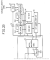
- Figure 2 is a block diagram comprising Figures 2A and 2B of a variable-length decoder according to a preferred embodiment of the present invention.
- Figures 3A through 3J are timing diagrams for explaining the operation of the Figure 2 apparatus.
- variable-length decoder decodes a variable-length codeword being variable-length-coded data into a prior-to-be-encoded state. More specifically, the variable-length decoder generates a level delayed by a run-length using variable-length-coded codeword of the video signal. Thus, the Figure 2 variable-length decoder outputs a shape of the data which can be used for an inverse transformation encoding operation.
- variable-length codewords are input to a first-in-first-out (FIFO) memory 11 in a pattern of a serial or parallel bitstream.
- FIFO memory 11 stores the input variable-length codewords, and outputs the firstly input N-bit data among the stored data to a latch 13, whenever a carry signal of "0" is applied thereto from an inverter 12.
- FIFO memory 11 outputs every N-bit among the bits input in the serial or parallel bitstream pattern in a parallel pattern of sequence. Accordingly, the most significant bit among the N-bit data output from FIFO memory 11 becomes the earliest bit among the identical N-bit data in the serial bitstream.
- the number of bits "N" is the number of bits having the longest length which the variable-length codewords can have.
- latch 13 latches the N-bit sequence output from FIFO memory 11
- latch 14 latches the data from latch 13
- latch 15 latches the data supplied from latch 13 individually.
- a first multiplexer 16 selects the output of latch 13 when the carry signal is "1”, and selects the output of latch 14 when the carry signal is zero, to supply the selected signal to a first barrel shifter 18.
- a second multiplexer 17 selects the output of latch 14 when the carry signal is "1", and selects the output of latch 15 when the carry signal is "0", to supply the selected signal to barrel shifter 18.
- Barrel shifter 18 outputs the N-bit data in the window shifted by the number of bits corresponding to the accumulated codeword length (ACL) among the 2N-bit sequence supplied from multiplexers 16 and 17, to a latch 21.
- the window shifting is performed by shifting the window by the ACL from the first bit of the N-bit sequence applied from the multiplexer 17.
- barrel shifter 18 when the ACL is "m", barrel shifter 18 outputs N-m bits except for m bits from the first bit in the N-bit sequence supplied from multiplexer 17 and m bits from the first bit in the N-bit sequence applied from multiplexer 16, to latch 21.
- Latch 21 latches the data supplied from barrel shifter 18 whenever a clock pulse is input thereto.
- Latch 22 latches the data supplied from second barrel shifter 23 which operates in the same way as that of barrel shifter 18 whenever a clock pulse is input thereto.
- Barrel shifter 23 outputs the N-bit sequence existing in the shifted window by a codeword length (CL) among the 2N-bit sequence supplied from latches 21 and 22, codeword length table 24 and latch 41.
- CL codeword length
- Codeword length table 24 outputs one of a first variable-length codeword length supplied from barrel shifter 23 according to state signal value and a codeword length corresponding to the state signal value, to an AND gate 25.
- the state data used in the preferred embodiment of the present invention is four-bit data.
- Codeword length table 24 is designed to output a codeword of "0" if the state signal value is “0”, outputs a codeword length obtained from the output data of barrel shifter 23 if the state signal value is between "1” and “14” and outputs a codeword of "N” if the state signal value is "15".
- the state signal value between "1” and "14” is used for discerning various codeword length tables.
- Such a state signal is supplied from an external apparatus (not shown) in an initial interval, that is, for a five clock pulses interval before the Figure 2 apparatus normal operation on the basis of the codeword length and the run-length obtained from the variable-length codeword.
- the state signal during the Figure 2 apparatus normal operation uses a codeword length obtained from codeword length table 24, or can be supplied from the external apparatus (not shown) in the same way as that of the initial interval.
- AND gate 25 supplies the codeword length from codeword length table 24 to a latch 26 during a run equivalent signal of "1" is applied from a first comparator 45, and supplies a value of "0" to a latch 26 during run equivalent of "0” is applied therefrom.
- Latch 26 latches the data supplied from AND gate 25 according to a clock pulse.
- Barrel shifter 23 shifts the window which determines the data output according to the codeword length from latch 26.
- the codeword length stored in latch 26 is supplied to accumulation operator 32.
- a latch 31 latches the accumulated codeword length output from accumulation operator 32 according to a clock pulse.
- Accumulation operator 32 adds the codeword length supplied from latch 26 to the accumulated codeword length supplied from latch 31. Also, accumulation operator 32 modulo-N-operates the added result value, and outputs the quotient as a carry signal and the residue as an accumulated codeword length.
- accumulation operator 32 outputs a carry signal of "1" and the accumulated codeword length being the reside resulting from the modulo-N-operation if a newly obtained accumulated codeword length is larger than or equal to "N"
- accumulation operator 32 outputs a carry signal of "0” and the accumulated codeword length being the residue resulting from the modulo-N-operation if a newly obtained accumulated codeword length is smaller than "N”.
- the accumulated codeword length output from accumulation operator 32 is supplied to latch 31 and barrel shifter 18, and the carry signal is supplied to inverter 12, latches 13, 14 and 15, and multiplexers 16 and 17.
- latches 22, 26 and 31 are cleared by an initial signals input to a low-edge trigger type clear end via inverter 6, respectively.
- Latch 41 is enabled according to a run equivalent signal applied from comparator 45, and latches the N-bit sequence supplied from barrel shifter 23 when a clock pulse is input thereto. That is, latch 41 latches the N-bit sequence from barrel shifter 23 according to a clock pulse input thereto, when the run equivalent signal is "1".
- Level table 42 outputs a level corresponding to a first variable-length codeword existing in the N-bit sequence supplied from latch 41. This level is supplied to latch 46, and the level latched in latch 46 is supplied to latch 48 when a clock pulse is input thereto.
- run table 43 outputs a run-length corresponding to a first variable-length codeword existing in the N-bit sequence supplied from latch 41.
- Comparator 45 compares the run-length from run table 43 with the counted value from a counter 44. Comparator 45 outputs a run equivalent signal of "1" if the run-length coincides with the counted value, while the comparator 45 outputs a run equivalent signal of "0" if not.
- the run equivalent signal being the output of comparator 45 is supplied to latches 41 and 47, gate circuit 52 and AND gate 25, respectively.
- Latch 47 latches the run equivalent signal from comparator 45 according to a clock pulse. The output of latch 47 is used as a clear signal of latch 48.
- latch 48 outputs a value of "0” if a value of "0” is applied from latch 47, and according to a clock pulse input, while latch 48 latches a level supplied from latch 46 if a value of "1" is applied thereto.
- a second comparator 51 compares the state signal with the block end signal (EOB) and outputs the comparison result to gate circuit 52.
- the comparator 51 outputs "1" if the EOB is equal to the state signal, and outputs "0" if not.
- the variable-length decoding with respect to a new block is normally performed by the output of comparator 51.
- Gate circuit 52 receives the inverted signal of the run equivalent signal, the inverted signal of the output of comparator 51 and the initial signal, logically multiplies the received signals by each other and outputs the result to counter 44.
- Counter 44 is an increment counter for counting the number of the clock pulse and is designed to receive the output signal of gate circuit 52 as a clear signal. Thus, counter 44 is cleared by run equivalent signal of "1" generated from comparator 45 when the run-length coincides with the counted value. Such a counter 44 counts the number of the clock pulses until the counted value coincides with the run length.
- An initial signal of Figure 3B has a high-level before a first clock pulse CLK1 is activated.
- the value of the state signal ( Figure 3C) is "15" when first clock pulse CLK1 through fourth clock pulse CLK4 are activated, is "0" when fifth clock pulse CLK5 is actiavted, and is varied according to the output of barrel shifter 23 after seventh clock pulse CLK7 is activated.
- FIFO memory 11 is defined so that the N-bit data is output in sequence of F1, F2, F3, F4, ... whenever the carry signal generated by accumulation operator 32 becomes “1", respectively.
- variable-length codeword of the serial bitstream is input and stored in FIFO memory 11 before the first clock pulse is activated.
- the initial signal of Figure 3B is applied to the Figure 2 apparatus via inverter 6.
- Latches 22, 26 and 31 are cleared by the initial signal, and gate circuit 52 outputs a value of "0" during a high-level interval of the initial signal.
- Counter 44 is cleared by a signal value of "0" from gate circuit 52.
- latch 26 outputs a codeword length of "0" as shown in Figure 3D.
- the output "0" of latch 26 is output to accumulation operator 32. Accumulation operator 32 adds the output of latch 31 cleared by the initial signal to the output of latch 26 and then performs a modulo-N-operation.
- latch 26 latches the codeword length "N” output from AND gate 25.
- Accumulation operator 32 adds the output "0” from latch 31 to the output "N” output from latch 26, and then outputs carry signal "1" by the modulo-N-operation of the result "N” and the accumulated codeword length "0".
- FIFO memory 11 outputs firstly input N-bit data "F1" among the stored data to latch 13 according to the carry signal inverted by inverter 12.
- the data latched in latches 13, 14, 15, 21, 22 and 41 are all "0” as shown in Figures 3E through 3J, respectively.
- comparator 45 outputs run equivalent signal "1” since a run-length is not supplied from run table 43.
- the run equivalent signal "1” is supplied to AND gate 25, which enables AND gate 25 to supply the output of codeword length table 24 to latch 26.
- the Figure 2 apparatus operates with respect to the second clock pulse CLK2 and third clock pulse CLK3. Then, if fifth clock pulse CLK5 is activated, latch 21 latches the data "F1" output from barrel shifter 18. Latch 15 latches the data "F1” output from latch 14. Latch 14 latches the data "F2” output from latch 13. Latch 13 latches the data "F3" output from FIFO memory 11.
- latch 26 since latch 26 latches the output "N" of AND gate 25, barrel shifter 23 outputs data the N-bit sequence in the window shifted by codeword length "N" output from latch 26, that is, data "F1" output from latch 21 to codeword length table 24 and latches 22 and 41, respectively.
- accumulation operator 32 outputs carry signal "1" and accumulated codeword length "0” according to the output "N” of latch 26 and the output "0" of latch 31.
- FIFO memory 11 outputs next N-bit data “F4" in response to carry signal "1” from accumulation operator 32.
- Multiplexer 16 supplies data “F3” from latch 13 to barrel shifter 18 in response to carry signal "1".
- Multiplexer 17 supplies data "F2” from latch 14 to barrel shifter 18 in response to carry signal "1".
- Barrel shifter 18 outputs data "F2” from multiplexer 17 to latch 21 in response to the accumulated codeword length "0” from accumulation operator 32.
- Codeword length table 24 outputs codeword length "0” according to the state signal value "0" when fourth clock pulse CLK4 is activated, to AND gate 25.
- AND gate 25 outputs codeword "0” to latch 26 according to run equivalent signal "1".
- latch 41 latches the data "F1" output from barrel shifter 23.
- Level table 42 outputs a level corresponding to a first variable-length codeword existing in the N-bit sequence "F1".
- Run table 43 receives data "F1" from latch 41 and outputs a run-length corresponding to a level output from level table 42 to comparator 45.
- Comparator 45 compares the run-length with the output "0" of counter 44, to thereby output run equivalent signal "1” if both are same, and to thereby output run equivalent signal "0” if not.
- a run-length corresponding to the level firstly output from level table 42 is defined as "0".
- comparator 45 outputs run equivalent signal "1".
- the run equivalent signal "1" is supplied to latches 41 and 47, gate circuit 52 and AND gate 25, respectively.
- latch 22 latches the data "F1" output from barrel shifter 23 according to fourth clock pulse CLK4.
- Latch 21 latches the data "F2" output from barrel shifter 18.
- Latch 15 latches the data "F2” output from latch 14.
- Latch 14 latches the data "F3” output from latch 13.
- Latch 13 latches the data "F4" output from FIFO memory 11.
- latch 26 since latch 26 latches the codeword length "0" output from AND gate 25, barrel shifter 23 outputs data "F1" output from latch 22 to codeword length table 24 and latches 22 and 41, respectively, in response to the output "0" of latch 26.
- codeword length table 24 outputs codeword length "X1" corresponding to the first variable-length codeword existing in the data "F1” applied from barrel shifter 23 as shown in Figure 3C.
- codeword length table 24 outputs codeword length "X1” corresponding to the first variable-length codeword existing in the data "F1".
- AND gate 25 outputs codeword "X1" from codeword length table 24 to latch 26 according to run equivalent signal "1" applied from comparator 45.
- Accumulation operator 32 performs an addition and a modulo-N-operation with respect to the output "0" of latch 26 and the output "0" of latch 31 according to the activation of fourth clock pulse CLK4, and outputs carry signal "0" and accumulated codeword length "0" according to the operation result.
- FIFO memory 11 does not output any data in response to carry signal "0".
- multiplexer 16 transfers the output "F3" of latch 14 to barrel shifter 18, while multiplexer 17 transfers the output "F2" of latch 15 to barrel shifter 18.
- Barrel shifter 18 outputs data "F2" output from latch 15 in response to accumulated codeword length "0".
- latch 46 latches the level output from level table 42, while latch 47 latches run equivalent signal "1" from comparator 45.
- Latch 41 latches data "F1" supplied from barrel shifter 23 in response to run equivalent signal "1".
- Level table 42 outputs a level corresponding to a first variable-length codeword existing in the data "F1”.
- Run table 43 receives data "F1” from latch 41 and outputs a run-length corresponding to a level output from level table 42 to comparator 45.
- Comparator 45 compares the run-length with the output "0" of counter 44, to thereby output run equivalent signal "1” according to the comparison result.
- the run equivalent signal "1" is supplied to latches 41 and 47, gate circuit 52 and AND gate 25, respectively.
- latch 22 latches the data "F1" output from barrel shifter 23 according to fifth clock pulse CLK5.
- Latch 21 latches the data "F2" output from barrel shifter 18.
- latch 15 has the data "F2” output from latch 14.
- Latch 14 has the data "F3” output from latch 13.
- Latch 13 has the data "F4" output from FIFO memory 11.
- FIFO memory 11 does not output any data since carry signal value is "0" when sixth clock pulse CLK6 is activated.
- barrel shifter 23 shifts the window by bits “X1” and outputs the N-bit data in the shifted window to codeword length table 24 and latches 22 and 41, respectively, in response to the output "X1" of latch 26.
- the output of barrel shifter 23 becomes bits from which the first variable-length codeword in the bitstream applied to FIFO memory 11 is excluded.
- the output of barrel shifter 23 is supplied to latches 22 and 41 and codeword length table 24.
- Codeword length table 245 outputs codeword length "X2" corresponding to the first variable-length codeword existing in the data output from barrel shifter 23.
- AND gate 25 outputs codeword "X2" output from codeword length table 24 to latch 26 in response to run equivalent signal "1".
- Accumulation operator 32 performs an addition and a modulo-N-operation with respect to the output "X1" of latch 26 and the output "0" of latch 31, and outputs the carry signal and the accumulated codeword length according to the operation result.
- the carry signal and accumulated codeword length output from accumulation operator 32 is determined by codeword "X1". If codeword length "X1" is larger than "N”, an accumulated codeword length being a residue obtained by dividing carry signal "1" and codeword length "X1" by "N”, is generated. On the other hand, if codeword length "X1" is smaller than “N”, the carry signal becomes “0” and codeword length "X1” becomes the accumulated codeword length output from accumulation operator 32.
- multiplexer 16 In response to the carry signal from accumulation operator 32, multiplexer 16 individually outputs the N-bit sequence from one of latches 13 and 14, while multiplexer 17 individually outputs the N-bit sequence from one of latches 14 and 15. Barrel shifter 18 shifts the window in response to the accumulated codeword length output from accumulation operator 32, and outputs the N-bit sequence in the shifted window to latch 21.
- latch 48 latches the level supplied from latch 46 in response to run equivalent signal "1" stored in latch 47.
- the data latched in latch 48 is a level corresponding to the first variable-length codeword in the bitstream applied to FIFO memory 11.
- Latch 46 latches again a level corresponding to the above-described first variable-length codeword.
- Latch 47 latches a run-length corresponding to the variable-length codeword.
- Latch 41 latches the N-bit data including bits from which the first variable-length codeword in the bitstream is excluded in response to run equivalent signal "1".
- the data latched in latch 41 is data corresponding to codeword "X2" output from codeword length table 24 by sixth clock pulse CLK6.
- Level table 42 outputs a level corresponding to the first variable-length codeword existing in the data output from latch 41.
- Run table 43 outputs a run-length corresponding to the level.
- the value supplied from counter 44 to comparator 45 becomes “0" since counter 44 is in the cleared state by previous run equivalent signal "1".
- Comparator 45 compares the output of run table 43 with the output of counter 44.
- Comparator 45 outputs a run equivalent signal of "1” or "0” according to the comparison result to latches 41 and 47, gate circuit 52 and AND gate 25.
- Comparator 45 outputs a run equivalent signal of "0" when the run-length output from run table 43 is not equal to the counted value output from counter 44.
- latch 41 maintains the data latched by the number of clock pulses corresponding to the run-length.
- Latch 22 also continuously has the data latched by the number of clock pulses corresponding to the run-length. If the run equivalent signal is "0", the data supplied to latch 26 becomes also "0". Thus, barrel shifters 18 and 23 have the data identical to the output data generated when the previous clock pulse is activated.
- the Figure 2 apparatus repeats the above-described procedures to decode the variable-length codewords existing in the bitstream. Thus, the operation of the Figure 2 apparatus will be apparent to a person having an ordinary skill in the art from the above-described embodiment.
- variable-length decoder can variable-length-decode the variable-length-coded codewords of the image signals at a high signal processing frequency.
- the variable-length decoder generates the data of "zeros" as many as the run-lengths and the following level, instead of generating a symbol corresponding to the variable-length codeword, thereby decoding the transformation-coded and variable-length-coded image signals at a signal processing frequency which is required in the HD-TV system, as well. Also, since the operation of the system should be delayed according to the run equivalent signal, a scope of the usable hardware which has been restricted by the signal processing frequency, can be broadened.
Abstract

Description
- The present invention relates to variable-length decoders for a data transmission system requiring a high signal processing frequency, and more particularly to variable-length decoders for decoding a variable-length-coded codeword of an image signal into a prior-to-be-encoded code.
- In a high-definition television (HD-TV), a high-definition video tape recorder (HD-VTR), a digital VTR, a digital camcoder or a multimedia system, both a video signal and an audio signal are converted into digital signals and the digitally converted signals are transmitted or stored in a recording medium, and then the transmitted or stored signals are decoded and reproduced. Such an encoding and decoding system requires a compression technology for compressing a greater amount of transmission data to maximize data transmission efficiency. There are a transformation encoding method, a differential pulse code modulation (DPCM) method, a vector quantization method, a variable-length coding method as generally-used methods for encoding video signals. These encoding methods are used to reduce a total amount of data by removing redundancy data included in digital signals.
- The variable-length encoding method among the above encoding methods includes a run-length encoding step and a modified Huffman encoding step. In the run-length encoding step, the number of continuous zeros is represented as run-lengths to reduce the number of the samples. The run-length being the number of the continuous zeros generated in the run-length encoding step and a magnitude or a level of a non-zero sample correspond to a signal codeword. For example, when certain data is input in sequence of "a, 0, 0, b, 0, 0, 0, 0, c, d, 0, e,..." where a, b, c, d and e are not equal to zero, the run-length encoded data is as follows: "[0, a], [2, b], [4, c] , [0, d] , [1, e], ...". Here, [0, a] represents that there is no zeros before the non-zero first level "a", and [2, b] represents that there are two zeros before the non-zero second level "b". As described above, the run-length encoded data is assigned with a short-length codeword in case of a high frequency of occurrence, and a long-length codeword in case of a low frequency of occurrence, according to a Huffman code table. Then, since it is not proper to lengthen the run-length without limitation, a variable-length coding is performed in units of a certain block. A bitstream of the variable-length-coded data includes a code for representing a start of a certain interval, a code for representing an end of a certain interval, a code for representing a video signal, a code for representing an end of block (EOB), a variety of control codes, and a state indication code. The state indication code represents what kind of property each code included in the bitstream has. That is, the state indication code is information for discerning the patterns of the codes constituting the bitstream with each other.
- Figure 1 shows a conventional variable-length decoder for decoding variable-length-coded data. The Figure 1 decoder is disclosed in more detail in "An Entropy Coding System for Digital HDTV Applications" (IEEE Transactions On Circuits And Systems For Video Technology, pp. 147-155, vol. 1 No. 1, March 1991, by Shaw-min Lei and Ming-Ting Sun). Thus, operation of the Figure 1 apparatus will be simply described below.
- In Figure 1, the variable-length-coded data is stored in a buffer (not shown). The buffer outputs N-bit data to a
first register 1 whenever a read signal is input thereto from acodeword length accumulator 5.First register 1 latches the N-bit variable-length-coded data output from the buffer whenever the read signal is input thereto fromcodeword length accumulator 5. Asecond register 2 latches the N-bit variable-length-coded data output fromfirst register 1. Abarrel shifter 3 receives the outputs of first andsecond registers codeword length accumulator 5. More specifically,barrel shifter 3 outputs the N-bit data stored in a window shifted by the codeword length accumulated incodeword length accumulator 5 to a programmable logic array (PLA) 4. PLA 4 decodes the N-bit variable-length-coded data output frombarrel shifter 3, and outputs a codeword length being the number of the bits used for decoding, tocodeword length accumulator 5.PLA 4 outputs a symbol and a code length of the symbol.Codeword length accumulator 5 adds the codeword length applied fromPLA 4 to the stored accumulated codeword length, and produces a newly accumulated codeword length.codeword length accumulator 5 generates a read signal if the newly produced accumulated codeword length is larger than or equal to N bits, and subtracts the number of bits N from the accumulated codeword length to calculate the accumulated codeword length to be supplied tobarrel shifter 3.Codeword length accumulator 5 outputs, however, the accumulated codeword length tobarrel shifter 3 if the accumulated codeword length is smaller than the N bits.Barrel shifter 3 outputs the data in a window shifted by the accumulated codeword length supplied fromcodeword length accumulator 5 among the 2 N-bit data supplied fromregisters PLA 4. The detailed descriptions of the Figure 1 apparatus including the operation ofbarrel shifter 3 appears in the above Shaw-min Lei and Ming-Ting Sun's reference. - On the other hand, U.S. Patent No. 5,245,338 to MinTing Sun issued on September 14, 1993 entitled "High-Speed Variable-Length Decoder" discloses a high-speed variable-length decoder capable of being used in a high-speed system such as a HD-TV.
- It is an aim of preferred embodiments of the present invention to provide a decoding apparatus for decoding variable-length-coded data having a different constitution from that of the disclosed prior art.
- According to the present invention, there is provided a variable-length decoder for image signals comprising:
a decoder for generating a run-length and level corresponding to a variable-length code starting at a first bit position in an N-bit sequence having the longest variable-length codeword of at least bit number N in a bitstream, generating a second run-length equivalent signal until the number of clock pulses coinciding with the run-length is input thereto, generating a first run equivalent signal if the number of the clock pulses coincides with the run-length, storing the generated level in response to the generated second run equivalent signal, and outputting the generated level in response to the generated first run equivalent signal, to thereby decode each variable-length codeword in the input bitstream based on a clock pulse generated according to a constant clock pulse rate;
first bit storage means coupled to the decoder so as to supply the stored N-bit sequence, for storing the N-bit input sequence for each clock pulse during an input of the first run equivalent signal from the decoder, and keeping the stored N-bit sequence for each clock pulse during an input of the second run equivalent signal;
codeword length generating means for receiving the N-bit sequence supplied from the first bit storage means and generating and outputting a codeword length corresponding to a variable-length codeword starting at a first bit position in the N-bit sequence for each clock pulse during an input of the first run equivalent signal from the decoder;
accumulation operation means for adding a previous accumulated codeword length to the codeword length supplied from the codeword length generation means, dividing the added result by the number of bits N, outputting an accumulated codeword length being a residue according to the divided result, and generating and outputting a carry signal if the quotient exists;
a buffer for storing the input bit stream, and sequentially outputting the N-bit sequence from the first bit position in the stored bitstream in response to the carry signal from the accumulation operation means;
second bit storage means for storing at least sequential 2N-bit sequence output from the buffer in response to the carry signal output from the accumulation operation means;
first shifter means for outputting an N-bit sequence starting at a bit position shifted by the accumulated codeword length starting at the first bit position among at least 2N-bit sequences stored in the second bit storage means in response to the carry signal and the accumulated codeword length;
third bit storage means for storing the N-bit sequence from the first shifter means for each clock pulse;
fourth bit storage means for storing the N-bit sequence supplied to the first storage means for each clock pulse; and
second shifter means for outputting an N-bit sequence having a first bit at a bit position shifted by a codeword length output from the codeword length generation means, from the first bit position among the 2N-bit sequences constructed so that the N-bit sequence stored in the fourth bit storage means is earlier than that of the N-bit sequence stored in the third bit storage means, to the first bit storage means, the fourth bit storage means and the codeword length generation means. - Suitably, said decoder comprises:
a level table for outputting a level corresponding to a variable-length codeword starting at the first bit position among the N-bit sequence from said first bit storage means;
a run table for receiving the N-bit sequence from said first bit storage means and outputting a run-length corresponding to the level output from said level table;
comparator means for generating a second run equivalent signal until a clock pulse coinciding with the run-length from said run table and generating a first run equivalent signal if a clock pulse coinciding with said run-length is applied thereto; and
an output portion for outputting the level from said level table if said first run equivalent signal is applied thereto, while the level from said level table is not output during said second run equivalent signal is applied thereto. - Suitably, said comparator means comprises:
a counter for counting for each clock pulse and outputting the counted value; and
a comparator for comparing the run-length from said run table with the counted value from said counter, wherein a first run equivalent signal is generated if both are equal to each other, and a second run equivalent signal is generated if both are not equal to each other, and wherein said first run equivalent signal is supplied as a clear signal of said counter. - Suitably, said comparator generates the first run equivalent signal for a five-clock pulse interval at the initial state.
- Suitably, said output portion comprises:
a first latch for storing the level from said level table for each clock pulse;
a second latch for storing the first and second run equivalent signals from said comparator means for each clock pulse; and
a third latch for storing and outputting the level supplied from said first latch for each clock pulse while the first run equivalent signal is applied thereto, while outputting a value of data "0" for each clock pulse while the second run equivalent signal is applied thereto. - Suitably, said codeword length generation means comprises:
a codeword length table for outputting a codeword length corresponding to a variable-length codeword starting at the first bit position among the N-bit sequence from said second shifter means;
a gate circuit for outputting the codeword length from said codeword length table while said first run equivalent signal is applied thereto; and
a fourth latch for storing the codeword length from said gate circuit for each clock pulse. - Suitably, said codeword length table for generating a codeword length so that the first N-bit sequence in the bitstream is stored in said third bit storage means within the five-clock pulse interval from the initial state.
- Suitably, said second bit storage means comprises:
a fifth latch for storing the N-bit sequence from said buffer for each clock pulse in response to the carry signal;
a sixth latch for storing the N-bit sequence from said fifth latch for each clock pulse in response to the carry signal; and
a seventh latch for storing the N-bit sequence from said sixth latch for each clock pulse in response to the carry signal, and
wherein said first shifter means comprises:
a first multiplexer for outputting the N-bit sequence from said fifth latch if the carry signal is applied from said accumulation operation means, and for outputting the N-bit sequence from said sixth latch if not;
a second multiplexer for outputting the N-bit sequence from said sixth latch if the carry signal is applied from said accumulation operation means, and for outputting the N-bit sequence from said seventh latch if not; and
a barrel shifter for receiving the 2N-bit sequence constructed so that the N-bit sequence from said second multiplexer is earlier than the N-bit sequence from said first multiplexer, from said first and second multiplexers, and outputting the N-bit sequence starting at a bit position shifted by the accumulated codeword length from said accumulation operation means at the first bit position among the 2N-bit sequence. - In the drawings:
- Figure 1 is a block diagram of a conventional variable-length decoder for decoding variable-length-coded data.
- Figure 2 is a block diagram comprising Figures 2A and 2B of a variable-length decoder according to a preferred embodiment of the present invention.
- Figures 3A through 3J are timing diagrams for explaining the operation of the Figure 2 apparatus.
- A preferred embodiment of the present invention will be described below in more detail, by way of example, with reference to the accompanying drawings Figures 2, and 3A through 3J.
- The Figure 2 variable-length decoder decodes a variable-length codeword being variable-length-coded data into a prior-to-be-encoded state. More specifically, the variable-length decoder generates a level delayed by a run-length using variable-length-coded codeword of the video signal. Thus, the Figure 2 variable-length decoder outputs a shape of the data which can be used for an inverse transformation encoding operation.
- The variable-length codewords are input to a first-in-first-out (FIFO) memory 11 in a pattern of a serial or parallel bitstream. FIFO memory 11 stores the input variable-length codewords, and outputs the firstly input N-bit data among the stored data to a
latch 13, whenever a carry signal of "0" is applied thereto from aninverter 12. FIFO memory 11 outputs every N-bit among the bits input in the serial or parallel bitstream pattern in a parallel pattern of sequence. Accordingly, the most significant bit among the N-bit data output from FIFO memory 11 becomes the earliest bit among the identical N-bit data in the serial bitstream. Here, the number of bits "N" is the number of bits having the longest length which the variable-length codewords can have. Thus, only one variable-length codeword or two variable-length codewords can exist in the N-bit sequence. With a clock pulse input, latch 13 latches the N-bit sequence output from FIFO memory 11, latch 14 latches the data fromlatch 13 and latch 15 latches the data supplied fromlatch 13 individually. These latches 13, 14 and 15 latch the supplied N-bit sequence according to a clock pulse input during an input of the carry signal of "1". Afirst multiplexer 16 selects the output oflatch 13 when the carry signal is "1", and selects the output oflatch 14 when the carry signal is zero, to supply the selected signal to afirst barrel shifter 18. A second multiplexer 17 selects the output oflatch 14 when the carry signal is "1", and selects the output oflatch 15 when the carry signal is "0", to supply the selected signal tobarrel shifter 18.Barrel shifter 18 outputs the N-bit data in the window shifted by the number of bits corresponding to the accumulated codeword length (ACL) among the 2N-bit sequence supplied frommultiplexers 16 and 17, to alatch 21. Here, the window shifting is performed by shifting the window by the ACL from the first bit of the N-bit sequence applied from the multiplexer 17. For example, when the ACL is "m",barrel shifter 18 outputs N-m bits except for m bits from the first bit in the N-bit sequence supplied from multiplexer 17 and m bits from the first bit in the N-bit sequence applied frommultiplexer 16, to latch 21.Latch 21 latches the data supplied frombarrel shifter 18 whenever a clock pulse is input thereto.Latch 22 latches the data supplied fromsecond barrel shifter 23 which operates in the same way as that ofbarrel shifter 18 whenever a clock pulse is input thereto.Barrel shifter 23 outputs the N-bit sequence existing in the shifted window by a codeword length (CL) among the 2N-bit sequence supplied fromlatches latch 41. - Codeword length table 24 outputs one of a first variable-length codeword length supplied from
barrel shifter 23 according to state signal value and a codeword length corresponding to the state signal value, to an ANDgate 25. The state data used in the preferred embodiment of the present invention is four-bit data. Codeword length table 24 is designed to output a codeword of "0" if the state signal value is "0", outputs a codeword length obtained from the output data ofbarrel shifter 23 if the state signal value is between "1" and "14" and outputs a codeword of "N" if the state signal value is "15". The state signal value between "1" and "14" is used for discerning various codeword length tables. Such a state signal is supplied from an external apparatus (not shown) in an initial interval, that is, for a five clock pulses interval before the Figure 2 apparatus normal operation on the basis of the codeword length and the run-length obtained from the variable-length codeword. Also, the state signal during the Figure 2 apparatus normal operation uses a codeword length obtained from codeword length table 24, or can be supplied from the external apparatus (not shown) in the same way as that of the initial interval. ANDgate 25 supplies the codeword length from codeword length table 24 to alatch 26 during a run equivalent signal of "1" is applied from afirst comparator 45, and supplies a value of "0" to alatch 26 during run equivalent of "0" is applied therefrom.Latch 26 latches the data supplied from ANDgate 25 according to a clock pulse.Barrel shifter 23 shifts the window which determines the data output according to the codeword length fromlatch 26. - The codeword length stored in
latch 26 is supplied toaccumulation operator 32. Alatch 31 latches the accumulated codeword length output fromaccumulation operator 32 according to a clock pulse.Accumulation operator 32 adds the codeword length supplied fromlatch 26 to the accumulated codeword length supplied fromlatch 31. Also,accumulation operator 32 modulo-N-operates the added result value, and outputs the quotient as a carry signal and the residue as an accumulated codeword length. That is,accumulation operator 32 outputs a carry signal of "1" and the accumulated codeword length being the reside resulting from the modulo-N-operation if a newly obtained accumulated codeword length is larger than or equal to "N", whereasaccumulation operator 32 outputs a carry signal of "0" and the accumulated codeword length being the residue resulting from the modulo-N-operation if a newly obtained accumulated codeword length is smaller than "N". The accumulated codeword length output fromaccumulation operator 32 is supplied to latch 31 andbarrel shifter 18, and the carry signal is supplied toinverter 12, latches 13, 14 and 15, andmultiplexers 16 and 17. On the other hand, latches 22, 26 and 31 are cleared by an initial signals input to a low-edge trigger type clear end viainverter 6, respectively. -
Latch 41 is enabled according to a run equivalent signal applied fromcomparator 45, and latches the N-bit sequence supplied frombarrel shifter 23 when a clock pulse is input thereto. That is,latch 41 latches the N-bit sequence frombarrel shifter 23 according to a clock pulse input thereto, when the run equivalent signal is "1". Level table 42 outputs a level corresponding to a first variable-length codeword existing in the N-bit sequence supplied fromlatch 41. This level is supplied to latch 46, and the level latched inlatch 46 is supplied to latch 48 when a clock pulse is input thereto. On the other hand, run table 43 outputs a run-length corresponding to a first variable-length codeword existing in the N-bit sequence supplied fromlatch 41.Comparator 45 compares the run-length from run table 43 with the counted value from acounter 44.Comparator 45 outputs a run equivalent signal of "1" if the run-length coincides with the counted value, while thecomparator 45 outputs a run equivalent signal of "0" if not. The run equivalent signal being the output ofcomparator 45 is supplied to latches 41 and 47,gate circuit 52 and ANDgate 25, respectively.Latch 47 latches the run equivalent signal fromcomparator 45 according to a clock pulse. The output oflatch 47 is used as a clear signal oflatch 48. Thus, latch 48 outputs a value of "0" if a value of "0" is applied fromlatch 47, and according to a clock pulse input, whilelatch 48 latches a level supplied fromlatch 46 if a value of "1" is applied thereto. - A
second comparator 51 compares the state signal with the block end signal (EOB) and outputs the comparison result togate circuit 52. Thecomparator 51 outputs "1" if the EOB is equal to the state signal, and outputs "0" if not. The variable-length decoding with respect to a new block is normally performed by the output ofcomparator 51.Gate circuit 52 receives the inverted signal of the run equivalent signal, the inverted signal of the output ofcomparator 51 and the initial signal, logically multiplies the received signals by each other and outputs the result to counter 44.Counter 44 is an increment counter for counting the number of the clock pulse and is designed to receive the output signal ofgate circuit 52 as a clear signal. Thus, counter 44 is cleared by run equivalent signal of "1" generated fromcomparator 45 when the run-length coincides with the counted value. Such a counter 44 counts the number of the clock pulses until the counted value coincides with the run length. - The operation of the Figure 2 apparatus having the above-described construction will be described below with reference to Figures 3A through 3J.
- An initial signal of Figure 3B has a high-level before a first clock pulse CLK1 is activated. The value of the state signal (Figure 3C) is "15" when first clock pulse CLK1 through fourth clock pulse CLK4 are activated, is "0" when fifth clock pulse CLK5 is actiavted, and is varied according to the output of
barrel shifter 23 after seventh clock pulse CLK7 is activated. For convenience, FIFO memory 11 is defined so that the N-bit data is output in sequence of F1, F2, F3, F4, ... whenever the carry signal generated byaccumulation operator 32 becomes "1", respectively. - The variable-length codeword of the serial bitstream is input and stored in FIFO memory 11 before the first clock pulse is activated. The initial signal of Figure 3B is applied to the Figure 2 apparatus via
inverter 6.Latches gate circuit 52 outputs a value of "0" during a high-level interval of the initial signal.Counter 44 is cleared by a signal value of "0" fromgate circuit 52. Accordingly, latch 26 outputs a codeword length of "0" as shown in Figure 3D. The output "0" oflatch 26 is output toaccumulation operator 32.Accumulation operator 32 adds the output oflatch 31 cleared by the initial signal to the output oflatch 26 and then performs a modulo-N-operation. In this case, since the output oflatch 31 is "0",accumulation operator 32 outputs carry signal "0" and the accumulated codeword length "0". FIFO memory 11 and latches 13, 14 and 15 do not operate by carry signal "0". The outputs oflatches comparator 45 outputs run equivalent signal "1" which is input to ANDgate 25. Here, the state signal has a value of "15" as shown in Figure 3C. Also, codeword length table 24 outputs codeword length "N" to ANDgate 25 in response to state signal "15". ANDgate 25 outputs codeword length "N" output from codeword length table 24 since the run equivalent signal output fromcomparator 45 is "1". - When first clock pulse CLK1 is activated, latch 26 latches the codeword length "N" output from AND
gate 25.Accumulation operator 32 adds the output "0" fromlatch 31 to the output "N" output fromlatch 26, and then outputs carry signal "1" by the modulo-N-operation of the result "N" and the accumulated codeword length "0". FIFO memory 11 outputs firstly input N-bit data "F1" among the stored data to latch 13 according to the carry signal inverted byinverter 12. After first clock pulse CLK1 is activated, the data latched inlatches comparator 45 outputs run equivalent signal "1" since a run-length is not supplied from run table 43. The run equivalent signal "1" is supplied to ANDgate 25, which enables ANDgate 25 to supply the output of codeword length table 24 to latch 26. - In this manner, the Figure 2 apparatus operates with respect to the second clock pulse CLK2 and third clock pulse CLK3. Then, if fifth clock pulse CLK5 is activated, latch 21 latches the data "F1" output from
barrel shifter 18.Latch 15 latches the data "F1" output fromlatch 14.Latch 14 latches the data "F2" output fromlatch 13.Latch 13 latches the data "F3" output from FIFO memory 11. Here, sincelatch 26 latches the output "N" of ANDgate 25,barrel shifter 23 outputs data the N-bit sequence in the window shifted by codeword length "N" output fromlatch 26, that is, data "F1" output fromlatch 21 to codeword length table 24 and latches 22 and 41, respectively. On the other hand,accumulation operator 32 outputs carry signal "1" and accumulated codeword length "0" according to the output "N" oflatch 26 and the output "0" oflatch 31. FIFO memory 11 outputs next N-bit data "F4" in response to carry signal "1" fromaccumulation operator 32.Multiplexer 16 supplies data "F3" fromlatch 13 tobarrel shifter 18 in response to carry signal "1". Multiplexer 17 supplies data "F2" fromlatch 14 tobarrel shifter 18 in response to carry signal "1".Barrel shifter 18 outputs data "F2" from multiplexer 17 to latch 21 in response to the accumulated codeword length "0" fromaccumulation operator 32. Codeword length table 24 outputs codeword length "0" according to the state signal value "0" when fourth clock pulse CLK4 is activated, to ANDgate 25. ANDgate 25 outputs codeword "0" to latch 26 according to run equivalent signal "1". - When fifth clock pulse CLK5 is activated, latch 41 latches the data "F1" output from
barrel shifter 23. Level table 42 outputs a level corresponding to a first variable-length codeword existing in the N-bit sequence "F1". Run table 43 receives data "F1" fromlatch 41 and outputs a run-length corresponding to a level output from level table 42 tocomparator 45.Comparator 45 compares the run-length with the output "0" ofcounter 44, to thereby output run equivalent signal "1" if both are same, and to thereby output run equivalent signal "0" if not. In the preferred embodiment of the present invention, a run-length corresponding to the level firstly output from level table 42 is defined as "0". Thus,comparator 45 outputs run equivalent signal "1". The run equivalent signal "1" is supplied to latches 41 and 47,gate circuit 52 and ANDgate 25, respectively. - On the other hand, latch 22 latches the data "F1" output from
barrel shifter 23 according to fourth clock pulse CLK4.Latch 21 latches the data "F2" output frombarrel shifter 18.Latch 15 latches the data "F2" output fromlatch 14.Latch 14 latches the data "F3" output fromlatch 13.Latch 13 latches the data "F4" output from FIFO memory 11. Here, sincelatch 26 latches the codeword length "0" output from ANDgate 25,barrel shifter 23 outputs data "F1" output fromlatch 22 to codeword length table 24 and latches 22 and 41, respectively, in response to the output "0" oflatch 26. Here, as the state signal, codeword length table 24 outputs codeword length "X1" corresponding to the first variable-length codeword existing in the data "F1" applied frombarrel shifter 23 as shown in Figure 3C. Thus, codeword length table 24 outputs codeword length "X1" corresponding to the first variable-length codeword existing in the data "F1". ANDgate 25 outputs codeword "X1" from codeword length table 24 to latch 26 according to run equivalent signal "1" applied fromcomparator 45. -
Accumulation operator 32 performs an addition and a modulo-N-operation with respect to the output "0" oflatch 26 and the output "0" oflatch 31 according to the activation of fourth clock pulse CLK4, and outputs carry signal "0" and accumulated codeword length "0" according to the operation result. Thus, FIFO memory 11 does not output any data in response to carry signal "0". Then, in response to carry signal "0",multiplexer 16 transfers the output "F3" oflatch 14 tobarrel shifter 18, while multiplexer 17 transfers the output "F2" oflatch 15 tobarrel shifter 18.Barrel shifter 18 outputs data "F2" output fromlatch 15 in response to accumulated codeword length "0". - When sixth clock pulse CLK6 is activated, latch 46 latches the level output from level table 42, while
latch 47 latches run equivalent signal "1" fromcomparator 45.Latch 41 latches data "F1" supplied frombarrel shifter 23 in response to run equivalent signal "1". Level table 42 outputs a level corresponding to a first variable-length codeword existing in the data "F1". Run table 43 receives data "F1" fromlatch 41 and outputs a run-length corresponding to a level output from level table 42 tocomparator 45.Comparator 45 compares the run-length with the output "0" ofcounter 44, to thereby output run equivalent signal "1" according to the comparison result. The run equivalent signal "1" is supplied to latches 41 and 47,gate circuit 52 and ANDgate 25, respectively. - On the other hand, latch 22 latches the data "F1" output from
barrel shifter 23 according to fifth clock pulse CLK5.Latch 21 latches the data "F2" output frombarrel shifter 18. Also, latch 15 has the data "F2" output fromlatch 14.Latch 14 has the data "F3" output fromlatch 13.Latch 13 has the data "F4" output from FIFO memory 11. Also, FIFO memory 11 does not output any data since carry signal value is "0" when sixth clock pulse CLK6 is activated. Sincelatch 26 latches the output "X1" from ANDgate 25 by the fifth clock pulse CLK5,barrel shifter 23 shifts the window by bits "X1" and outputs the N-bit data in the shifted window to codeword length table 24 and latches 22 and 41, respectively, in response to the output "X1" oflatch 26. Thus, in this case, the output ofbarrel shifter 23 becomes bits from which the first variable-length codeword in the bitstream applied to FIFO memory 11 is excluded. The output ofbarrel shifter 23 is supplied to latches 22 and 41 and codeword length table 24. Codeword length table 245 outputs codeword length "X2" corresponding to the first variable-length codeword existing in the data output frombarrel shifter 23. ANDgate 25 outputs codeword "X2" output from codeword length table 24 to latch 26 in response to run equivalent signal "1". -
Accumulation operator 32 performs an addition and a modulo-N-operation with respect to the output "X1" oflatch 26 and the output "0" oflatch 31, and outputs the carry signal and the accumulated codeword length according to the operation result. In this case, the carry signal and accumulated codeword length output fromaccumulation operator 32 is determined by codeword "X1". If codeword length "X1" is larger than "N", an accumulated codeword length being a residue obtained by dividing carry signal "1" and codeword length "X1" by "N", is generated. On the other hand, if codeword length "X1" is smaller than "N", the carry signal becomes "0" and codeword length "X1" becomes the accumulated codeword length output fromaccumulation operator 32. In response to the carry signal fromaccumulation operator 32,multiplexer 16 individually outputs the N-bit sequence from one oflatches latches Barrel shifter 18 shifts the window in response to the accumulated codeword length output fromaccumulation operator 32, and outputs the N-bit sequence in the shifted window to latch 21. - If a seventh clock pulse CLK7 is activated, latch 48 latches the level supplied from
latch 46 in response to run equivalent signal "1" stored inlatch 47. Here, the data latched inlatch 48 is a level corresponding to the first variable-length codeword in the bitstream applied to FIFO memory 11.Latch 46 latches again a level corresponding to the above-described first variable-length codeword.Latch 47 latches a run-length corresponding to the variable-length codeword.Latch 41 latches the N-bit data including bits from which the first variable-length codeword in the bitstream is excluded in response to run equivalent signal "1". The data latched inlatch 41 is data corresponding to codeword "X2" output from codeword length table 24 by sixth clock pulse CLK6. Level table 42 outputs a level corresponding to the first variable-length codeword existing in the data output fromlatch 41. Run table 43 outputs a run-length corresponding to the level. Here, the value supplied from counter 44 tocomparator 45 becomes "0" sincecounter 44 is in the cleared state by previous run equivalent signal "1".Comparator 45 compares the output of run table 43 with the output ofcounter 44.Comparator 45 outputs a run equivalent signal of "1" or "0" according to the comparison result tolatches gate circuit 52 and ANDgate 25.Comparator 45 outputs a run equivalent signal of "0" when the run-length output from run table 43 is not equal to the counted value output fromcounter 44. When the run-length corresponding to the level output from level table 42 is not "0" according to the run equivalent signal "0" output fromcomparator 45,latch 41 maintains the data latched by the number of clock pulses corresponding to the run-length.Latch 22 also continuously has the data latched by the number of clock pulses corresponding to the run-length. If the run equivalent signal is "0", the data supplied to latch 26 becomes also "0". Thus,barrel shifters - When the state signal equals block end signal EOB, the output of
comparator 51 clearscounter 44. The Figure 2 apparatus performs a normal decoding operation with respect to a new block according to the clear operation of thecounter 44. - The Figure 2 apparatus repeats the above-described procedures to decode the variable-length codewords existing in the bitstream. Thus, the operation of the Figure 2 apparatus will be apparent to a person having an ordinary skill in the art from the above-described embodiment.
- As described above, the variable-length decoder according to the present invention can variable-length-decode the variable-length-coded codewords of the image signals at a high signal processing frequency. The variable-length decoder generates the data of "zeros" as many as the run-lengths and the following level, instead of generating a symbol corresponding to the variable-length codeword, thereby decoding the transformation-coded and variable-length-coded image signals at a signal processing frequency which is required in the HD-TV system, as well. Also, since the operation of the system should be delayed according to the run equivalent signal, a scope of the usable hardware which has been restricted by the signal processing frequency, can be broadened.
- The reader's attention is directed to all papers and documents which are filed concurrently with or previous to this specification in connection with this application and which are open to public inspection with this specification, and the contents of all such papers and documents are incorporated herein by reference.
- All of the features disclosed in this specification (including any accompanying claims, abstract and drawings) , and/or all of the steps of any method or process so disclosed, may be combined in any combination, except combinations where at least some of such features and/or steps are mutually exclusive.
- Each feature disclosed in this specification (including any accompanying claims, abstract and drawings), may be replaced by alternative features serving the same, equivalent or similar purpose, unless expressly stated otherwise. Thus, unless expressly stated otherwise, each feature disclosed is one example only of a generic series of equivalent or similar features.
- The invention is not restricted to the details of the foregoing embodiment(s). The invention extends to any novel one, or any novel combination, of the features disclosed in this specification (including any accompanying claims, abstract and drawings), or to any novel one, or any novel combination, of the steps of any method or process so disclosed.
Claims (8)
- A variable-length decoder for image signals comprising:
a decoder (42-48) for generating a run-length and level corresponding to a variable-length code starting at a first bit position in an N-bit sequence having the longest variable-length codeword of at least bit number N in a bitstream, generating a second run-length equivalent signal until the number of clock pulses coinciding with the run-length is input thereto, generating a first run equivalent signal if the number of the clock pulses coincides with the run-length, storing the generated level in response to the generated second run equivalent signal, and outputting the generated level in response to the generated first run equivalent signal, to thereby decode each variable-length codeword in the input bitstream based on a clock pulse generated according to a constant clock pulse rate;
first bit storage means (41) coupled to the decoder (42-48) so as to supply the stored N-bit sequence, for storing the N-bit input sequence for each clock pulse during an input of the first run equivalent signal from the decoder (42-48), and keeping the stored N-bit sequence for each clock pulse during an input of the second run equivalent signal;
codeword length generating means (24, 25) for receiving the N-bit sequence supplied from the first bit storage means (41) and generating and outputting a codeword length corresponding to a variable-length codeword starting at a first bit position in the N-bit sequence for each clock pulse during an input of the first run equivalent signal from the decoder (42-48);
accumulation operation means (32) for adding a previous accumulated codeword length to the codeword length supplied from the codeword length generation means (24,25), dividing the added result by the number of bits N, outputting an accumulated codeword length being a residue according to the divided result, and generating and outputting a carry signal if the quotient exists;
a buffer (11) for storing the input bit stream, and sequentially outputting the N-bit sequence from the first bit position in the stored bitstream in response to the carry signal from the accumulation operation means (32);
second bit storage means (13, 14, 15) for storing at least sequential 2N-bit sequence output from the buffer (11) in response to the carry signal output from the accumulation operation means (32);
first shifter means (18) for outputting an N-bit sequence starting at a bit position shifted by the accumulated codeword length starting at the first bit position among at least 2N-bit sequences stored in the second bit storage means (13, 14, 15) in response to the carry signal and the accumulated codeword length;
third bit storage means (21) for storing the N-bit sequence from the first shifter means (18) for each clock pulse;
fourth bit storage means (22) for storing the N-bit sequence supplied to the first storage means (41) for each clock pulse; and
second shifter means (23) for outputting an N-bit sequence having a first bit at a bit position shifted by a codeword length output from the codeword length generation means (24, 25), from the first bit position among the 2N-bit sequences constructed so that the N-bit sequence stored in the fourth bit storage means (22) is earlier than that of the N-bit sequence stored in the third bit storage means (21), to the first bit storage means (41), the fourth bit storage means (22) and the codeword length generation means (24, 25). - A variable-length decoder (42-48) according to claim 1, wherein said decoder comprises:
a level table (42) for outputting a level corresponding to a variable-length codeword starting at the first bit position among the N-bit sequence from said first bit storage means (41);
a run table (43) for receiving the N-bit sequence from said first bit storage means (41) and outputting a run-length corresponding to the level output from said level table (42);
comparator means (44, 45) for generating a second run equivalent signal until a clock pulse coinciding with the run-length from said run table (43) and generating a first run equivalent signal if a clock pulse coinciding with said run-length is applied thereto; and
an output portion (46, 47, 48) for outputting the level from said level table if said first run equivalent signal is applied thereto, while the level from said level table (42) is not output during said second run equivalent signal is applied thereto. - A variable-length decoder according to claim 2, wherein said comparator means (44, 45) comprises:
a counter (44) for counting for each clock pulse and outputting the counted value; and
a comparator (45) for comparing the run-length from said run table (43) with the counted value from said counter (44), wherein a first run equivalent signal is generated if both are equal to each other, and a second run equivalent signal is generated if both are not equal to each other, and wherein said first run equivalent signal is supplied as a clear signal of said counter (44). - A variable-length decoder according to claim 3, wherein said comparator (44, 45) generates the first run equivalent signal for a five-clock pulse interval at the initial state.
- A variable-length decoder according to any one of claims 2 to 4, wherein said output portion (46, 47, 48) comprises:
a first latch (46) for storing the level from said level table (42) for each clock pulse;
a second latch (47) for storing the first and second run equivalent signals from said comparator means (44, 45) for each clock pulse; and
a third latch (48) for storing and outputting the level supplied from said first latch (46) for each clock pulse while the first run equivalent signal is applied thereto, while outputting a value of data "0" for each clock pulse while the second run equivalent signal is applied thereto. - A variable-length decoder according to any preceding claim, wherein said codeword length generation means (24, 25) comprises:
a codeword length table (24) for outputting a codeword length corresponding to a variable-length codeword starting at the first bit position among the N-bit sequence from said second shifter means (23);
a gate circuit (25) for outputting the codeword length from said codeword length table (24) while said first run equivalent signal is applied thereto; and
a fourth latch (26) for storing the codeword length from said gate circuit (25) for each clock pulse. - A variable-length decoder according to claim 6, wherein said codeword length table (24) for generating a codeword length so that the first N-bit sequence in the bitstream is stored in said third bit storage means (22) within the five-clock pulse interval from the initial state.
- A variable-length decoder according to any preceding claim, wherein said second bit storage means (13, 14, 15) comprises:
a fifth latch (13) for storing the N-bit sequence from said buffer (11) for each clock pulse in response to the carry signal;
a sixth latch (14) for storing the N-bit sequence from said fifth latch (13) for each clock pulse in response to the carry signal; and
a seventh latch (15) for storing the N-bit sequence from said sixth latch (14) for each clock pulse in response to the carry signal, and
wherein said first shifter means (16, 17, 18) comprises:
a first multiplexer (16) for outputting the N-bit sequence from said fifth latch (13) if the carry signal is applied from said accumulation operation means, and for outputting the N-bit sequence from said sixth latch (14) if not;
a second multiplexer (17) for outputting the N-bit sequence from said sixth latch (14) if the carry signal is applied from said accumulation operation means, and for outputting the N-bit sequence from said seventh latch (15) if not; and
a barrel shifter (18) for receiving the 2N-bit sequence constructed so that the N-bit sequence from said second multiplexer (17) is earlier than the N-bit sequence from said first multiplexer (16), from said first and second multiplexers (16, 17), and outputting the N-bit sequence starting at a bit position shifted by the accumulated codeword length from said accumulation operation means (32) at the first bit position among the 2N-bit sequence.
Applications Claiming Priority (2)
| Application Number | Priority Date | Filing Date | Title |
|---|---|---|---|
| KR1019940009922A KR0152032B1 (en) | 1994-05-06 | 1994-05-06 | Variable length decoder for image signal |
| KR9409922 | 1994-05-06 |
Publications (2)
| Publication Number | Publication Date |
|---|---|
| EP0681404A2 true EP0681404A2 (en) | 1995-11-08 |
| EP0681404A3 EP0681404A3 (en) | 1996-10-16 |
Family
ID=19382582
Family Applications (1)
| Application Number | Title | Priority Date | Filing Date |
|---|---|---|---|
| EP19950303102 Withdrawn EP0681404A3 (en) | 1994-05-06 | 1995-05-05 | Variable-length decoder. |
Country Status (5)
| Country | Link |
|---|---|
| US (1) | US5696506A (en) |
| EP (1) | EP0681404A3 (en) |
| JP (1) | JP3032134B2 (en) |
| KR (1) | KR0152032B1 (en) |
| CN (1) | CN1085009C (en) |
Cited By (4)
| Publication number | Priority date | Publication date | Assignee | Title |
|---|---|---|---|---|
| EP0769852A1 (en) * | 1995-10-19 | 1997-04-23 | Samsung Electronics Co., Ltd. | Variable length decoding using a FIFO |
| WO1997024810A1 (en) * | 1995-12-28 | 1997-07-10 | Philips Electronics N.V. | Variable length decoder |
| EP0802681A2 (en) * | 1996-03-25 | 1997-10-22 | Lg Electronics Inc. | Variable length code decoder |
| EP0862275A2 (en) * | 1997-02-27 | 1998-09-02 | Siemens Aktiengesellschaft | Decoder for variable length codes |
Families Citing this family (11)
| Publication number | Priority date | Publication date | Assignee | Title |
|---|---|---|---|---|
| KR0178201B1 (en) * | 1995-08-31 | 1999-05-01 | 배순훈 | Variable length decoding apparatus |
| US5835035A (en) * | 1995-12-28 | 1998-11-10 | Philips Electronics North America Corporation | High performance variable length decoder with two-word bit stream segmentation and related method |
| CN100521787C (en) * | 1996-05-28 | 2009-07-29 | 松下电器产业株式会社 | Image predicting and encoding method |
| JP3520670B2 (en) * | 1996-06-28 | 2004-04-19 | ソニー株式会社 | Variable length code processing device and image processing device |
| JPH11215008A (en) * | 1998-01-27 | 1999-08-06 | Oki Electric Ind Co Ltd | Decoding circuit |
| US6215424B1 (en) * | 1998-12-16 | 2001-04-10 | Thomson Licensing S.A. | System for variable length codeword processing suitable for video and other applications |
| JP4559652B2 (en) * | 2000-03-24 | 2010-10-13 | パナソニック株式会社 | Variable length decoding circuit |
| TWI245571B (en) * | 2004-11-05 | 2005-12-11 | Ali Corp | Variable-length decoding apparatus and method for the image format of a digital video camera |
| CN100466748C (en) * | 2004-11-12 | 2009-03-04 | 扬智科技股份有限公司 | Digital camera image format variable length decoding apparatus and method |
| KR20090117580A (en) * | 2008-05-08 | 2009-11-12 | 엘지전자 주식회사 | A method of generating codewords |
| CN105718402B (en) * | 2016-01-13 | 2021-04-20 | 福州瑞芯微电子股份有限公司 | Programmable timing generator |
Citations (10)
| Publication number | Priority date | Publication date | Assignee | Title |
|---|---|---|---|---|
| EP0384782A1 (en) * | 1989-02-24 | 1990-08-29 | General Electric Company | Non-destructive lossless image coder |
| EP0453113A1 (en) * | 1990-03-28 | 1991-10-23 | Sony Corporation | Coding and decoding apparatus of variable length date |
| US5173695A (en) * | 1990-06-29 | 1992-12-22 | Bell Communications Research, Inc. | High-speed flexible variable-length-code decoder |
| US5181031A (en) * | 1991-07-30 | 1993-01-19 | Lsi Logic Corporation | Method and apparatus for decoding huffman codes by detecting a special class |
| US5208593A (en) * | 1991-07-30 | 1993-05-04 | Lsi Logic Corporation | Method and structure for decoding Huffman codes using leading ones detection |
| EP0552908A2 (en) * | 1992-01-20 | 1993-07-28 | Canon Kabushiki Kaisha | Decoding apparatus |
| US5245338A (en) * | 1992-06-04 | 1993-09-14 | Bell Communications Research, Inc. | High-speed variable-length decoder |
| EP0562419A2 (en) * | 1992-03-26 | 1993-09-29 | General Instrument Corporation Of Delaware | Variable length code word decoder for use in digital communication systems |
| US5264847A (en) * | 1991-10-04 | 1993-11-23 | Sony United Kingdom Ltd. | Data decoder |
| US5369405A (en) * | 1992-05-19 | 1994-11-29 | Goldstar Co., Ltd. | Coefficient generation apparatus for variable length decoder |
Family Cites Families (1)
| Publication number | Priority date | Publication date | Assignee | Title |
|---|---|---|---|---|
| KR960003452B1 (en) * | 1992-12-31 | 1996-03-13 | 대우전자주식회사 | Vlc |
-
1994
- 1994-05-06 KR KR1019940009922A patent/KR0152032B1/en not_active IP Right Cessation
-
1995
- 1995-05-02 JP JP10865695A patent/JP3032134B2/en not_active Expired - Fee Related
- 1995-05-05 EP EP19950303102 patent/EP0681404A3/en not_active Withdrawn
- 1995-05-05 CN CN95106522A patent/CN1085009C/en not_active Expired - Fee Related
- 1995-05-08 US US08/436,866 patent/US5696506A/en not_active Expired - Fee Related
Patent Citations (10)
| Publication number | Priority date | Publication date | Assignee | Title |
|---|---|---|---|---|
| EP0384782A1 (en) * | 1989-02-24 | 1990-08-29 | General Electric Company | Non-destructive lossless image coder |
| EP0453113A1 (en) * | 1990-03-28 | 1991-10-23 | Sony Corporation | Coding and decoding apparatus of variable length date |
| US5173695A (en) * | 1990-06-29 | 1992-12-22 | Bell Communications Research, Inc. | High-speed flexible variable-length-code decoder |
| US5181031A (en) * | 1991-07-30 | 1993-01-19 | Lsi Logic Corporation | Method and apparatus for decoding huffman codes by detecting a special class |
| US5208593A (en) * | 1991-07-30 | 1993-05-04 | Lsi Logic Corporation | Method and structure for decoding Huffman codes using leading ones detection |
| US5264847A (en) * | 1991-10-04 | 1993-11-23 | Sony United Kingdom Ltd. | Data decoder |
| EP0552908A2 (en) * | 1992-01-20 | 1993-07-28 | Canon Kabushiki Kaisha | Decoding apparatus |
| EP0562419A2 (en) * | 1992-03-26 | 1993-09-29 | General Instrument Corporation Of Delaware | Variable length code word decoder for use in digital communication systems |
| US5369405A (en) * | 1992-05-19 | 1994-11-29 | Goldstar Co., Ltd. | Coefficient generation apparatus for variable length decoder |
| US5245338A (en) * | 1992-06-04 | 1993-09-14 | Bell Communications Research, Inc. | High-speed variable-length decoder |
Non-Patent Citations (1)
| Title |
|---|
| SIGNAL PROCESSING OF HDTV, 3, TURIN, SEPT. 4 - 6, 1991, no. WORKSHOP 4, 4 September 1991, YASUDA H;CHIARIGLIONE L, pages 547-554, XP000379993 STAMMNITZ P ET AL: "HARDWARE IMPLEMENTATION OF A CODEC FOR DIGITAL HDTV RECORDING" * |
Cited By (7)
| Publication number | Priority date | Publication date | Assignee | Title |
|---|---|---|---|---|
| EP0769852A1 (en) * | 1995-10-19 | 1997-04-23 | Samsung Electronics Co., Ltd. | Variable length decoding using a FIFO |
| US5892791A (en) * | 1995-10-19 | 1999-04-06 | Samsung Electronics Co., Ltd. | High-speed variable length decoding apparatus |
| WO1997024810A1 (en) * | 1995-12-28 | 1997-07-10 | Philips Electronics N.V. | Variable length decoder |
| EP0802681A2 (en) * | 1996-03-25 | 1997-10-22 | Lg Electronics Inc. | Variable length code decoder |
| EP0802681A3 (en) * | 1996-03-25 | 2002-04-10 | Lg Electronics Inc. | Variable length code decoder |
| EP0862275A2 (en) * | 1997-02-27 | 1998-09-02 | Siemens Aktiengesellschaft | Decoder for variable length codes |
| EP0862275A3 (en) * | 1997-02-27 | 1999-08-11 | Siemens Aktiengesellschaft | Decoder for variable length codes |
Also Published As
| Publication number | Publication date |
|---|---|
| JPH0879747A (en) | 1996-03-22 |
| EP0681404A3 (en) | 1996-10-16 |
| KR0152032B1 (en) | 1998-10-15 |
| CN1119813A (en) | 1996-04-03 |
| US5696506A (en) | 1997-12-09 |
| CN1085009C (en) | 2002-05-15 |
| JP3032134B2 (en) | 2000-04-10 |
| KR950035400A (en) | 1995-12-30 |
Similar Documents
| Publication | Publication Date | Title |
|---|---|---|
| US5627917A (en) | Variable length coding system having a zig-zag FIFO for selectively storing each data coefficient and zero-run count | |
| JP3007496B2 (en) | Variable length decoder | |
| US5696506A (en) | Apparatus for variable-length decoding image signals using a run equivalent signal | |
| US5162795A (en) | Coding and decoding apparatus of variable length data | |
| US5491480A (en) | Variable length decoder using serial and parallel processing | |
| US5436626A (en) | Variable-length codeword encoder | |
| JP3247804B2 (en) | Data compression method, data compression / decompression method, code word data number limiting device | |
| US5892791A (en) | High-speed variable length decoding apparatus | |
| US5706001A (en) | Run-length decoding apparatus for use in a video signal decoding system | |
| EP0655842A2 (en) | High speed variable length code decoding apparatus | |
| JP2831888B2 (en) | HDTV decoder | |
| EP0708565B1 (en) | Variable-length decoding apparatus using relative addressing | |
| US5313203A (en) | Coding apparatus and method for coding information symbol strings by assigning fixed length codes thereto | |
| US5663725A (en) | VLC decoder with sign bit masking | |
| EP0802681B1 (en) | Variable length code decoder | |
| US5432512A (en) | Apparatus for decoding variable length codes | |
| US6020835A (en) | Code decoding apparatus | |
| Rudberg et al. | New approaches to high speed Huffman decoding | |
| JPH08223055A (en) | Variable-length cord decoder | |
| KR0166721B1 (en) | Variable length decoder | |
| EP0703675B1 (en) | Variable length decoding method and apparatus | |
| US5736945A (en) | Circuit for zero-run developing RUN/LEVEL sets and method for zero-run developing the same | |
| US6115500A (en) | Method and device for compressing image data | |
| KR0125126B1 (en) | High-speed apparatus for decoding variable length code | |
| JP4466382B2 (en) | Codeword extraction apparatus and method, decoding apparatus, and image reproduction apparatus |
Legal Events
| Date | Code | Title | Description |
|---|---|---|---|
| PUAI | Public reference made under article 153(3) epc to a published international application that has entered the european phase |
Free format text: ORIGINAL CODE: 0009012 |
|
| 17P | Request for examination filed |
Effective date: 19950517 |
|
| AK | Designated contracting states |
Kind code of ref document: A2 Designated state(s): DE FR GB |
|
| PUAL | Search report despatched |
Free format text: ORIGINAL CODE: 0009013 |
|
| AK | Designated contracting states |
Kind code of ref document: A3 Designated state(s): DE FR GB |
|
| 17Q | First examination report despatched |
Effective date: 20010309 |
|
| STAA | Information on the status of an ep patent application or granted ep patent |
Free format text: STATUS: THE APPLICATION IS DEEMED TO BE WITHDRAWN |
|
| 18D | Application deemed to be withdrawn |
Effective date: 20030621 |