EP0682341A1 - Electronic apparatus using information memory medium - Google Patents
Electronic apparatus using information memory medium Download PDFInfo
- Publication number
- EP0682341A1 EP0682341A1 EP94925628A EP94925628A EP0682341A1 EP 0682341 A1 EP0682341 A1 EP 0682341A1 EP 94925628 A EP94925628 A EP 94925628A EP 94925628 A EP94925628 A EP 94925628A EP 0682341 A1 EP0682341 A1 EP 0682341A1
- Authority
- EP
- European Patent Office
- Prior art keywords
- information
- unit
- specific
- indication
- tracks
- Prior art date
- Legal status (The legal status is an assumption and is not a legal conclusion. Google has not performed a legal analysis and makes no representation as to the accuracy of the status listed.)
- Granted
Links
- 238000001514 detection method Methods 0.000 claims abstract description 20
- 238000003860 storage Methods 0.000 claims description 16
- 230000010365 information processing Effects 0.000 claims description 15
- 238000003672 processing method Methods 0.000 claims description 9
- 238000004220 aggregation Methods 0.000 claims description 2
- 230000002776 aggregation Effects 0.000 claims description 2
- 230000003287 optical effect Effects 0.000 description 15
- 238000003491 array Methods 0.000 description 10
- 201000004059 subependymal giant cell astrocytoma Diseases 0.000 description 8
- 239000000758 substrate Substances 0.000 description 5
- 239000004065 semiconductor Substances 0.000 description 4
- 229920003023 plastic Polymers 0.000 description 3
- 238000010586 diagram Methods 0.000 description 2
- 230000002093 peripheral effect Effects 0.000 description 2
- -1 acryl Chemical group 0.000 description 1
- 239000004411 aluminium Substances 0.000 description 1
- 229910052782 aluminium Inorganic materials 0.000 description 1
- XAGFODPZIPBFFR-UHFFFAOYSA-N aluminium Chemical compound [Al] XAGFODPZIPBFFR-UHFFFAOYSA-N 0.000 description 1
- 230000015572 biosynthetic process Effects 0.000 description 1
- 230000006835 compression Effects 0.000 description 1
- 238000007906 compression Methods 0.000 description 1
- 238000004590 computer program Methods 0.000 description 1
- 230000000694 effects Effects 0.000 description 1
- 238000004519 manufacturing process Methods 0.000 description 1
- 239000000463 material Substances 0.000 description 1
- 229910052751 metal Inorganic materials 0.000 description 1
- 239000002184 metal Substances 0.000 description 1
- 238000000034 method Methods 0.000 description 1
- 239000004033 plastic Substances 0.000 description 1
- 239000004417 polycarbonate Substances 0.000 description 1
- 229920000515 polycarbonate Polymers 0.000 description 1
- 230000002265 prevention Effects 0.000 description 1
- 230000005236 sound signal Effects 0.000 description 1
- 239000012780 transparent material Substances 0.000 description 1
- 125000000391 vinyl group Chemical group [H]C([*])=C([H])[H] 0.000 description 1
- 229920002554 vinyl polymer Polymers 0.000 description 1
Images


Classifications
-
- G—PHYSICS
- G06—COMPUTING; CALCULATING OR COUNTING
- G06F—ELECTRIC DIGITAL DATA PROCESSING
- G06F3/00—Input arrangements for transferring data to be processed into a form capable of being handled by the computer; Output arrangements for transferring data from processing unit to output unit, e.g. interface arrangements
- G06F3/05—Digital input using the sampling of an analogue quantity at regular intervals of time, input from a/d converter or output to d/a converter
-
- G—PHYSICS
- G11—INFORMATION STORAGE
- G11B—INFORMATION STORAGE BASED ON RELATIVE MOVEMENT BETWEEN RECORD CARRIER AND TRANSDUCER
- G11B23/00—Record carriers not specific to the method of recording or reproducing; Accessories, e.g. containers, specially adapted for co-operation with the recording or reproducing apparatus ; Intermediate mediums; Apparatus or processes specially adapted for their manufacture
- G11B23/28—Indicating or preventing prior or unauthorised use, e.g. cassettes with sealing or locking means, write-protect devices for discs
- G11B23/283—Security features, e.g. digital codes
-
- G—PHYSICS
- G11—INFORMATION STORAGE
- G11B—INFORMATION STORAGE BASED ON RELATIVE MOVEMENT BETWEEN RECORD CARRIER AND TRANSDUCER
- G11B20/00—Signal processing not specific to the method of recording or reproducing; Circuits therefor
- G11B20/00086—Circuits for prevention of unauthorised reproduction or copying, e.g. piracy
- G11B20/00876—Circuits for prevention of unauthorised reproduction or copying, e.g. piracy wherein physical copy protection means are attached to the medium, e.g. holograms, sensors, or additional semiconductor circuitry
-
- G—PHYSICS
- G11—INFORMATION STORAGE
- G11B—INFORMATION STORAGE BASED ON RELATIVE MOVEMENT BETWEEN RECORD CARRIER AND TRANSDUCER
- G11B23/00—Record carriers not specific to the method of recording or reproducing; Accessories, e.g. containers, specially adapted for co-operation with the recording or reproducing apparatus ; Intermediate mediums; Apparatus or processes specially adapted for their manufacture
- G11B23/38—Visual features other than those contained in record tracks or represented by sprocket holes the visual signals being auxiliary signals
- G11B23/40—Identifying or analogous means applied to or incorporated in the record carrier and not intended for visual display simultaneously with the playing-back of the record carrier, e.g. label, leader, photograph
-
- G—PHYSICS
- G11—INFORMATION STORAGE
- G11B—INFORMATION STORAGE BASED ON RELATIVE MOVEMENT BETWEEN RECORD CARRIER AND TRANSDUCER
- G11B7/00—Recording or reproducing by optical means, e.g. recording using a thermal beam of optical radiation by modifying optical properties or the physical structure, reproducing using an optical beam at lower power by sensing optical properties; Record carriers therefor
- G11B7/002—Recording, reproducing or erasing systems characterised by the shape or form of the carrier
- G11B7/0037—Recording, reproducing or erasing systems characterised by the shape or form of the carrier with discs
-
- G—PHYSICS
- G11—INFORMATION STORAGE
- G11B—INFORMATION STORAGE BASED ON RELATIVE MOVEMENT BETWEEN RECORD CARRIER AND TRANSDUCER
- G11B7/00—Recording or reproducing by optical means, e.g. recording using a thermal beam of optical radiation by modifying optical properties or the physical structure, reproducing using an optical beam at lower power by sensing optical properties; Record carriers therefor
- G11B7/004—Recording, reproducing or erasing methods; Read, write or erase circuits therefor
- G11B7/005—Reproducing
-
- G—PHYSICS
- G11—INFORMATION STORAGE
- G11B—INFORMATION STORAGE BASED ON RELATIVE MOVEMENT BETWEEN RECORD CARRIER AND TRANSDUCER
- G11B7/00—Recording or reproducing by optical means, e.g. recording using a thermal beam of optical radiation by modifying optical properties or the physical structure, reproducing using an optical beam at lower power by sensing optical properties; Record carriers therefor
- G11B7/24—Record carriers characterised by shape, structure or physical properties, or by the selection of the material
- G11B7/24094—Indication parts or information parts for identification
-
- A—HUMAN NECESSITIES
- A63—SPORTS; GAMES; AMUSEMENTS
- A63F—CARD, BOARD, OR ROULETTE GAMES; INDOOR GAMES USING SMALL MOVING PLAYING BODIES; VIDEO GAMES; GAMES NOT OTHERWISE PROVIDED FOR
- A63F2300/00—Features of games using an electronically generated display having two or more dimensions, e.g. on a television screen, showing representations related to the game
- A63F2300/20—Features of games using an electronically generated display having two or more dimensions, e.g. on a television screen, showing representations related to the game characterised by details of the game platform
- A63F2300/201—Playing authorisation given at platform level
-
- A—HUMAN NECESSITIES
- A63—SPORTS; GAMES; AMUSEMENTS
- A63F—CARD, BOARD, OR ROULETTE GAMES; INDOOR GAMES USING SMALL MOVING PLAYING BODIES; VIDEO GAMES; GAMES NOT OTHERWISE PROVIDED FOR
- A63F2300/00—Features of games using an electronically generated display having two or more dimensions, e.g. on a television screen, showing representations related to the game
- A63F2300/20—Features of games using an electronically generated display having two or more dimensions, e.g. on a television screen, showing representations related to the game characterised by details of the game platform
- A63F2300/206—Game information storage, e.g. cartridges, CD ROM's, DVD's, smart cards
Definitions
- the present invention relates to an electronic device for reading information stored in an information storage medium, particularly an information processing device for optically reading program information stored in a CD-ROM to play a game.
- a new security system for CD-ROMs are proposed in Japanese Patent Application No. Hei 05-185740/1993, and International Application PCT/JP 94/01243 filed based on the priority claimed from the Japanese patent application.
- This security system detects whether or not specific indications, such as trademarks or others, are indicated at predetermined parts of CD-ROM discs, whereby the discs are judged to be genuine products or counterfeits.
- One object of the present invention is to provide an electronic device with a new security system built in, which can effectively reject or exclude counterfeit products.
- Another object of the present invention is to provide an electronic device and an information processing method which can reduce a reading time of reading a specific security indication.
- Another object of the present invention is to provide an electronic device and an information processing method which make for counterfeiters to release security systems more difficult.
- Another object of the present invention is to provide an electronic device and an information processing method which can effectively expel or exclude counterfeit information storage medium from the market even when security systems are released.
- Still another object of the present invention is to provide an information processing method which can effectively reject or exclude use of counterfeit information storage medium.
- the electronic device comprises a medium mounting unit on which an information storage medium having visually recognizable indication information is to be mounted, a detection unit for detecting specific information selected out of unit information constituting the indication information, and an output unit having reference information corresponding to the indication information, said output unit comparing the specific information with comparison information in the reference information corresponding to the specific information and generating an output of the compared result.
- all of information of an indication for the security check is not required to be detected.
- information of a selected part of the indication is detected, whereby a reading time of information of the indication can be short.
- the electronic device is characterized in that said detection unit includes a selection unit selecting at random the specific information out of the unit information.
- the specific part to be selected from a unit information constituting the indication information is changed at random for every read out, so that when a counterfeiter makes an information storage medium agreeable or compatible to the electronic device of the present invention, he has to illegally use the same indication as indication information born by an authentic information storage medium. Counterfeits can be more effectively expelled.
- the CD-ROM device comprises a CD-ROM mounting unit on which a CD-ROM having visually recognizable indication information is to be mounted, a detection unit for detecting specific information selected at random out of unit information constituting the indication information, and an output unit having reference information corresponding to the indication information, said output unit comparing the specific information with comparison information in the reference information corresponding to the specific information and generating an output of the compared result.
- all of information of an indication for the security check born by a CD-ROM is not requested to be detected, but only a specific selected part of the indication is detected, whereby a time required for reading out the indication information can be made short. Furthermore, because a specific selected part to be read out of the indication is randomly changed by the detection unit for every reading out a counterfeiter, who wants to make a CD-ROM software compatible to an authentic CD-ROM player, should have to illegally use the same indication as that born on an authentic CD-ROM. Thus, counterfeits can be more effectively expelled.
- the electronic device comprises a disc mounting unit on which is to be mounted a disc having an information recording region with information recorded with pits and a predetermined region defined over a plurality of tracks, a detection unit for detecting information in specific tracks selected out of said plurality of tracks, a storing unit storing reference information corresponding to a specific indication, and a judging unit comparing information obtained from the specific tracks with the reference information to judge whether or not the specific indication is indicated in the predetermined region.
- a time required for reading out a specific indication can be shortened, because it is not required to detect all of a plurality of tracks defined for the security check, but required to detect only a selected few specific ones.
- the electronic device comprises a disc mounting unit on which is to be mounted a disc having a region with program information recorded with pits, a predetermined region defined over a plurality of tracks, and a region with a specific indication visually recognizably formed with an aggregation of pits within the predetermined region, a detection unit detecting information out of specific tracks selected from said plurality of tracks, a storing unit for storing reference information corresponding to the specific indication, and a comparison unit comparing information obtained from the specific tracks with the reference information.
- a specific indication for the security check is indicated over a plurality of tracks, but for the security check, information is detected from specific selected tracks, whereby a time required for reading the specific indication can be shortened.
- the electronic device is characterized in that said detecting unit includes a selection unit selecting at random the specific tracks out of said plurality of tracks.
- the information processing device comprises a storing unit storing reference information corresponding to a specific indication the use of which is legally prohibited to a person other than those authorized, a disc mounting unit on which is to be mounted a disc having an information recording region with information recorded with pits, and a predetermined region defined over a plurality of tracks, a selection unit selecting specific tracks at random out of said plurality of tracks, a detection unit optically detecting information recorded with pits in the specific tracks, a comparison unit comparing the information obtained from the specific tracks with the reference information, and a reading unit for reading the information in the information recording region in response to an output from the comparison unit when the information obtained from the specific tracks agrees to the information in the reference information corresponding to the specific tracks.
- information is detected only from specific tracks for the security check, whereby a time required for reading out a specific indication can be made shortened.
- specific tracks are changed at random for every security check, so that a counterfeiter should have to indicate the same indication as a specific indication born on the authentic discs. Illegal indication can be legally accused, whereby counterfeits can be very effectively expelled.
- the electronic device comprises a reference information storing unit for storing reference information, a disc mounting unit on which is to be mounted a disc having an information recording zone with information recorded with pits, an indication forming zone defined at part different from the information storing zone, and a plurality of indication regions defined in the indication forming zone, a selecting unit selecting at random a specific indication region out of the plurality of indication regions, a detection unit optically detecting indication information recorded with pits in the specific indication region selected at random, and a comparison unit comparing the indication information detected out of the specific indication region with the reference information, and a control unit operable in response to an output from the comparison unit.
- a plurality of indication regions of a disc are detected for the security check, so that the security is further ensured.
- a required detection time is made shortened while the security is further ensured, because it is not required to detect all of the plural indication regions, but required to detect only a specific indication region selected at random.
- the electronic device is characterized in that said selecting unit selects at random specific tracks out of a plurality of tracks forming the specific indication region, and said comparison unit compares the information detected from the specific track with the reference information.
- the information processing method comprises the steps of detecting specific information selected out of unit information which is visually recognizably indicated on an information storage medium, and comparing the selected specific information with reference information corresponding to said unit information.
- a time required for reading out the indication information can be shortened, because it is not required to detect all of information for the security check required to detect only but a selected specific part of information.
- the information processing method is characterized in that the detection of the specific information is conducted by selecting at random the specific information out of the unit information.
- a specific part to be selected from unit information of indication is changed at random for every read out.
- a counterfeiter who wants to make an information storage medium which can be read by the information processing method of the present invention, should have to illegally indicate the same indication as indicated on an authentic information storage medium. Counterfeiting can be further effectively expelled.
- FIG. 1 is a perspective view of a game machine incorporating the security check system according to the present invention.
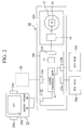
- FIG. 2 is a block diagram of the game machine incorporating the security check system according to the present invention.
- FIG. 3 is a plan view of a CD-ROM which the security check system according to the present invention is applied to.
- FIG. 4 is a view of one example of indications on the CD-ROM to be security-checked.
- FIG. 5 is a partial sectional view of the CD-ROM which the security check according to the present invention is applied to.
- FIGs. 6A - 6C are views detailing formation of an indication the security check according to the present invention is applied to.
- FIG. 7 is a block diagram of a reading unit for executing the security check according to the present invention.
- FIG. 8 is a view explaining an original data for checking as a reference for comparison.
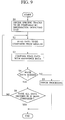
- FIG. 9 is a flow chart of the operation of the read unit for the security check according to the present invention.
- FIGs. 10A - 10D are plan views of other examples of the CD-ROM which the security check according to the present invention is applied to.
- a game machine 10 includes a control unit 10a and a CD-ROM control unit 10b.
- the control unit 10a includes a game control unit 21 for controlling a game, an output interface 22 for supplying audio signals and video signals, input interfaces 23a, 23b for receiving operational signals, and input/output interfaces 24a, 24b for receiving/supplying a game program and data.
- the output interface 22, the input interfaces 23a, 23b, and the input/output interfaces 24a, 24b are connected to the game control unit 21.
- control unit 10a is connected to a television unit 25 as a display unit for displaying contents of a game, and to various controllers, e.g., joy pads 26a, 26b, for manipulating proceeding of the game through the input interfaces 23a, 23b.
- controllers e.g., joy pads 26a, 26b
- the game machine comprises the game machine body 10, the television unit 25, the joy pads, etc.
- the numeral 10 refers herein to the main body of the game machine.
- the numeral 10 sometimes may refer in general to a game machine to which peripherals such as a joy stick are connected.
- the game machine 10 receives a game cartridge 28 in a cartridge receiver 29 of the control unit 10a and can conduct a game in accordance with a game program stored in a semiconductor ROM or RAM of the game cartridge 28.
- the game program stored in the semiconductor ROM or RAM is transmitted to the game control unit 21 through the input/output interface 24a.
- the CD-ROM control unit 10b includes a CD-ROM mount or drive unit 11 and an optical pickup 16.
- a CD-ROM 12 is mounted on the CD-ROM mount 11, so that program information stored in the CD-ROM 12 is detected by the optical pickup 16.
- the read game program information is supplied to the game control unit 21 through the input/output interface 24a, and the game is ready for conducting.
- the game cartridge 28 and the CD-ROM 12 function as information storing medium, and the cartridge port or receiver 29 and the CD-ROM mount unit 11 function as a medium port.
- the CD-ROM 12 is formed in a disk as shown in FIG. 3 of thin transparent plastics and has a center hole 12a formed in the center of the disc.
- the plastic substrate 13 of the CD-ROM 12 has a program region 14 with a game program information recorded with pits between a read-in region 14a and a read-out region 14b.
- the program region 14 which is an information recorded region has a trademark indication region 15 defined in a rectangular area over 100 - 200 tracks adjacent to the read-in region 14a without game program information recorded.
- the region 15 may be referred to as "trademark indication region", "indication region” or "predetermined region/part".
- data A to be compared which is a specific indication (see FIG. 4) is provided.
- the data A to be compared is formed with a set of pits and is recognized as pit array information when read by the optical pickup 16 provided in the CD-ROM control unit 10b.
- the data A to be compared is indication information stored in the trademark indication region 15 which is visually recognizable, and can be, in addition to a trademark, a mark, logotype, a pattern, character or others.
- the CD-ROM 12 stores image information in the form of a set of pits together with game program information in the form of a group of pits 35 in the upper side of the disc substrate 31 of transparent plastics, such as polycarbonate, acryl, vinyl polychloride or others.
- the upper side 33 with the pits 35 formed in is covered with a reflecting layer 36 which is a metal layer of aluminium or others, and is covered further with a protection layer 37, whereby an outer surface 38 is formed.
- the protection layer 37 is usually formed of an opaque material, and a title, a design and an author of a game software, and a trademark, etc. designated by a licenser in a case that production of the game software is licensed by a third party can be indicated in the outer surface 38.
- the information stored in the CD-ROM 12 is read by causing a laser beam to enter into the disc substrate 31 from the underside surface 34 thereof and reflect at the reflection layer 36 to be detected by the optical pickup 16 disposed facing the underside surface 34.
- a set of pits in the trademark indication region 15 is formed to be recognizable as a required shape visually from the underside surface 34, which is an optical detecting surface.
- a data A to be compared e.g., "SEGA” is formed in a set of pits as shown in FIG. 6A.
- the data A to be compared is visible (visually recognizable as a mark "SEGA") from the underside surface 34, the optical detecting surface, of the disc substrate 31, as shown in FIG. 5.
- Each dot making up the letters "SEGA” comprises a set of pit arrays enclosed by the broken line A in FIG. 6B, and the part with no letters comprises a set of pit arrays C in FIG. 6B.
- a region enclosed by the broken line A is formed in one visible dot by longitudinally 70 tracks and transversely 12 pit arrays.
- the pit arrays B provides a unit at which areas covered with pits are made a maximum as shown in FIG. 6C (A)
- the pit arrays C provides a unit at which areas covered with pits are made a minimum as shown in FIG. 6C (B).
- Such dots are arranged at required positions to form letters.
- the letters, e.g., "SEGA" in FIG. 6A are formed in the trademark indication region 15 defined over substantially 1000 tracks.
- an indication in the predetermined region 15 of the disc substrate 31 is formed visible (readable or recognizable) as letters from the underside surface 34 which is the optical detecting surface (see FIG. 5), but may be formed visible from the upper surface 38 opposite to the optical detecting surface (see FIG. 5).
- the protection layer 37 is formed of a transparent material so that a specific indication can be visible from the outer surface 38.
- the game machine 10 includes a reading unit 17.
- the unit 17 is connected to the optical pickup 16 through the input/output interface 24b.
- the unit 17 includes an information detecting unit 18, and a comparison unit 19.
- the information detecting unit 18 includes a random number generating circuit 20 which functions as a selection unit.
- the information detecting unit 18 controls reading positions of the optical pickup 16 with respect to the CD-ROM 12, and generates outputs of detection signals (a) commanding the optical pickup to read specific tracks which are located in the trademark indication region 15 and are to be compared.
- the specific tracks are selected at random out of a plurality of tracks which are composed of pit arrays forming comparison data A. The selection is determined by a random number generated by the random number generating circuit 20.
- the optical pickup 16 selects and reads specific pit arrays which are specific information out of pit arrays which indicates a plurality of unit information.
- the pit array information (b) read from the specific tracks are supplied to the comparison unit 19.
- Specific tracks to be read by the optical pickup 16 can be obtained by selecting several units at which one track is defined as a unit, and also may be obtained by selectively several units at which a plurality of tracks are defined as a unit.
- the comparison unit 19 stores base data D (see FIG. 8) as digital signals in a semiconductor ROM.
- the base data D is reference information or standard information for judging agreement of data A therewith.
- the base data D correspond to a reference indication such as the specific indication "SEGA" as shown in FIG. 8.
- the digital reference data corresponding to the specific indication "SEGA” are stored in a semiconductor ROM in which a reference unit is a set of data corresponding to each track consisting of a set of pits.
- the specific indication A is formed on the CD-ROM disc as the same group of pits as the reference indication D.
- the specific indication A to be compared is detected at its selected tracks in which a comparison unit is a respective track consisting of a set of pits.
- the comparison unit 19 generates comparison result information (c) as a comparison result.
- the comparison unit 19 functions as a storage for storing base or reference data corresponding to the specific indication D; as an output unit for comparing data to be compared, which are indicative of comparison pit array information of a specific indication A, with the reference data and generating an output based on the comparison result; and as a judging unit for judging whether or not the specific indication is displayed.
- the game machine 10 is powered on to start the checking operation.
- the information detecting unit 18 determines specific tracks to be compared (Step S1).
- the specific tracks to be compared for the data A are determined as, for example, Track 1, Track 2, etc. corresponding to random numbers generated by the random number generating circuit 20. Track numbers corresponding to a predetermined number of tracks are selected at random.
- Step 2 a part of the data to be compared is read by the optical pickup 16 from the CD-ROM 12 which is a medium to be checked.
- the optical pickup 16 is moved to a position corresponding to the specific tracks to read information out of pit arrays of the specific tracks.
- Step S3 The information read out of the pit arrays and the reference data D are compared by the comparison unit 19.
- the comparison unit 19 judges whether or not both data agree to each other (Step S4).
- the comparison unit 19 judges NO and conducts an error processing (Step S5). And the checking operation is over.
- Step S6 judges whether or not all the data determined in Step S1 have been compared.
- a judgement is YES after comparison of all the data to be compared, then the comparison operation is over.
- a judgement is NO, namely, all the steps of comparison have not been finished, then the step is returned to Step S2 to read data to be compared. This operation is repeated until all of information to be checked have been compared and judged.
- the information detecting unit 18 When both information agree to each other, the information detecting unit 18 reads program information in the program region 14. When both information disagree to each other, the information detecting unit 18 does not read the program information in the program region 14 or stops the game.
- track numbers to be checked are selected for each checking operation, and concurrently with selection of track numbers, a number of tracks to be checked, on a data amount to be checked, for each checking operation may be varied.
- the reading unit 17 selects at random specific tracks to be compared out of the tracks without checking all the tracks, whereby the checking can be conducted in a short period of time. Furthermore, such shortened time of the checking allows larger data of larger numbers of tracks or larger images to be set as data A to be compared, which improves the security effect.
- tracks to be checked are changed at the start of every checking operation, data A to be compared stored in the CD-ROM 12 as a medium to be checked must be complete data, i.e., a complete image.
- more accurate check is enabled by varying a number of specific tracks for every checking operation.
- a counterfeiter who wants to fabricate a CD-ROM acceptable in an electronic device or information processing device of an authentic game machine or others, is required to indicate at a predetermined position of the CD-ROM a designated specific indication as data A to be compared corresponding to base data D as a reference or reference information stored in the authentic electronic device or information processing device. If he does, he will be illegally accused as an infringer of a proprietary right.
- the designated specific indication is exemplified by a trademark, a logotype, and a tradename protected by Trademark Law, and a design, a mark, an image, etc. protected by Design Law. Designs, marks, images, etc. are protected in some states by Design and Patent Law, Copyright Law, etc.
- the reference data D is subjected to information compression processing to reduce a data amount, whereby the read unit 17 occupies a smaller area, and reduces costs.
- the region for a specific indication on a CD-ROM to be security-checked is not limited to the position as shown in FIG. 3 and can be varied.
- a zone 15a in which game program information is not written in is defined inside the program region 14, or an information recording zone, along an inner circumference of the disc, and the region 15 for indicating a specific indication with a set of pits may be formed in the zone 15a.
- a zone 15b in which game program information is not written in is defined outside the program region 14, or an information recording zone, along an outer circumference of the disc, and the region 15 for indicating a specific indication with a set of pits may be formed in the zone 15b.
- these zones 15a, 15b are defined as indication forming zones on parts other than the information recording zone, and the region 15 is defined as an indication region in the zone 15a or 15b.
- a plural number of the region 15 may be formed continuously or at a certain interval in the zone 15b.
- the same specific indication may be indicated in the respective regions 15, or two different indications may be indicated alternately in the respective regions 15.
- those of the regions 15 may be selected at random as data A to be compared for the checking out of the plural regions 15, based on random numbers generated by the random number generating circuit 20. Combination of the regions 15 at positions selected at random, and tracks in the selected regions selected at random can ensure the security.
- the zone 15b may be provided outside the read-out region 14b of the CD-ROM 12, so that the zone 15b can be set exactly separated from the program region 14 storing information, whereby controls for reading the information and for detecting a specific indication can be facilitated.
- a reference indication is able to hinder an unauthorized person from indicating the same.
- the reference indication may be owned, or its use may be granted by a license agreement.
- a plural number of the same indication may be used, or a combination of a plural number of different indications may be used.
- an indication formed in the region 15 of the CD-ROM 12 is formed in a visible size and shape, and may be formed in a sector along a peripheral edge of the CD-ROM 12.
- the present invention is applicable to security systems for electronic devices for reading information for use from information storage mediums storing game programs, musical softwares, dictionaries, computer programs, etc., especially applicable to security systems for information processing devices for optically reading program information stored in CD-ROMs to play games.
Abstract
Description
- The present invention relates to an electronic device for reading information stored in an information storage medium, particularly an information processing device for optically reading program information stored in a CD-ROM to play a game.
- Musical CDs and data information CD-ROMs can be reproduced by CD drives as long as they meet standards even if they are counterfeits. This does not cease counterfeit manufacturers. As a countermeasure to this, various security systems have been proposed for the prevention of unauthorized copying game softwares which have been developed as results of large investments of a large number of man powers and much time.
- A new security system for CD-ROMs are proposed in Japanese Patent Application No. Hei 05-185740/1993, and International Application PCT/JP 94/01243 filed based on the priority claimed from the Japanese patent application. This security system detects whether or not specific indications, such as trademarks or others, are indicated at predetermined parts of CD-ROM discs, whereby the discs are judged to be genuine products or counterfeits.
- In the security system proposed in the above-described applications, when a specific indication is read, the entire specific indication is read, which unavoidably requires a certain reading time. Especially in a case that a specific indication is visibly displayed on an information storage surface with using a group of pits over a plurality of tracks, all said tracks have to be read, which takes much reading time.
- One object of the present invention is to provide an electronic device with a new security system built in, which can effectively reject or exclude counterfeit products.
- Another object of the present invention is to provide an electronic device and an information processing method which can reduce a reading time of reading a specific security indication.
- Another object of the present invention is to provide an electronic device and an information processing method which make for counterfeiters to release security systems more difficult.
- Another object of the present invention is to provide an electronic device and an information processing method which can effectively expel or exclude counterfeit information storage medium from the market even when security systems are released.
- Still another object of the present invention is to provide an information processing method which can effectively reject or exclude use of counterfeit information storage medium.
- The electronic device according to one embodiment of the present invention comprises a medium mounting unit on which an information storage medium having visually recognizable indication information is to be mounted, a detection unit for detecting specific information selected out of unit information constituting the indication information, and an output unit having reference information corresponding to the indication information, said output unit comparing the specific information with comparison information in the reference information corresponding to the specific information and generating an output of the compared result.
- According to this embodiment, all of information of an indication for the security check is not required to be detected. Thereinstead, information of a selected part of the indication is detected, whereby a reading time of information of the indication can be short.
- The electronic device according to another embodiment of the present invention is characterized in that said detection unit includes a selection unit selecting at random the specific information out of the unit information.
- According to this embodiment, the specific part to be selected from a unit information constituting the indication information is changed at random for every read out, so that when a counterfeiter makes an information storage medium agreeable or compatible to the electronic device of the present invention, he has to illegally use the same indication as indication information born by an authentic information storage medium. Counterfeits can be more effectively expelled.
- The CD-ROM device according to still another embodiment of the present invention comprises a CD-ROM mounting unit on which a CD-ROM having visually recognizable indication information is to be mounted, a detection unit for detecting specific information selected at random out of unit information constituting the indication information, and an output unit having reference information corresponding to the indication information, said output unit comparing the specific information with comparison information in the reference information corresponding to the specific information and generating an output of the compared result.
- According to this embodiment, all of information of an indication for the security check born by a CD-ROM is not requested to be detected, but only a specific selected part of the indication is detected, whereby a time required for reading out the indication information can be made short. Furthermore, because a specific selected part to be read out of the indication is randomly changed by the detection unit for every reading out a counterfeiter, who wants to make a CD-ROM software compatible to an authentic CD-ROM player, should have to illegally use the same indication as that born on an authentic CD-ROM. Thus, counterfeits can be more effectively expelled.
- The electronic device according to still another embodiment of the present invention comprises a disc mounting unit on which is to be mounted a disc having an information recording region with information recorded with pits and a predetermined region defined over a plurality of tracks, a detection unit for detecting information in specific tracks selected out of said plurality of tracks, a storing unit storing reference information corresponding to a specific indication, and a judging unit comparing information obtained from the specific tracks with the reference information to judge whether or not the specific indication is indicated in the predetermined region.
- According to this embodiment, a time required for reading out a specific indication can be shortened, because it is not required to detect all of a plurality of tracks defined for the security check, but required to detect only a selected few specific ones.
- The electronic device according to still another embodiment of the present invention comprises a disc mounting unit on which is to be mounted a disc having a region with program information recorded with pits, a predetermined region defined over a plurality of tracks, and a region with a specific indication visually recognizably formed with an aggregation of pits within the predetermined region, a detection unit detecting information out of specific tracks selected from said plurality of tracks, a storing unit for storing reference information corresponding to the specific indication, and a comparison unit comparing information obtained from the specific tracks with the reference information.
- According to this embodiment, a specific indication for the security check is indicated over a plurality of tracks, but for the security check, information is detected from specific selected tracks, whereby a time required for reading the specific indication can be shortened.
- The electronic device according to still another embodiment of the present invention is characterized in that said detecting unit includes a selection unit selecting at random the specific tracks out of said plurality of tracks.
- According to this embodiment, because specific tracks to be detected for the security check are changed at random by the detecting unit for every reading out, a counterfeiter, who wants fabricate an information storage medium agreeable or compatible to the authentic electronic device, has to illegally indicate the same indication as the specific indication born or authentic information storage mediums.
- The information processing device according to still another embodiment of the present invention comprises a storing unit storing reference information corresponding to a specific indication the use of which is legally prohibited to a person other than those authorized, a disc mounting unit on which is to be mounted a disc having an information recording region with information recorded with pits, and a predetermined region defined over a plurality of tracks, a selection unit selecting specific tracks at random out of said plurality of tracks, a detection unit optically detecting information recorded with pits in the specific tracks, a comparison unit comparing the information obtained from the specific tracks with the reference information, and a reading unit for reading the information in the information recording region in response to an output from the comparison unit when the information obtained from the specific tracks agrees to the information in the reference information corresponding to the specific tracks.
- According to this embodiment, information is detected only from specific tracks for the security check, whereby a time required for reading out a specific indication can be made shortened. In addition, specific tracks are changed at random for every security check, so that a counterfeiter should have to indicate the same indication as a specific indication born on the authentic discs. Illegal indication can be legally accused, whereby counterfeits can be very effectively expelled.
- The electronic device according to still another embodiment of the present invention comprises a reference information storing unit for storing reference information, a disc mounting unit on which is to be mounted a disc having an information recording zone with information recorded with pits, an indication forming zone defined at part different from the information storing zone, and a plurality of indication regions defined in the indication forming zone, a selecting unit selecting at random a specific indication region out of the plurality of indication regions, a detection unit optically detecting indication information recorded with pits in the specific indication region selected at random, and a comparison unit comparing the indication information detected out of the specific indication region with the reference information, and a control unit operable in response to an output from the comparison unit.
- According to this embodiment, a plurality of indication regions of a disc are detected for the security check, so that the security is further ensured. In addition, a required detection time is made shortened while the security is further ensured, because it is not required to detect all of the plural indication regions, but required to detect only a specific indication region selected at random.
- The electronic device according to still another embodiment of the present invention is characterized in that said selecting unit selects at random specific tracks out of a plurality of tracks forming the specific indication region, and said comparison unit compares the information detected from the specific track with the reference information.
- According to this embodiment, because little data are detected for the security check out of selected specific tracks which are also selected from a selected specific indication region, increase of a read time is suppressed while the security is much improved, whereby counterfeits can be very effectively expelled.
- The information processing method according to one embodiment of the present invention comprises the steps of detecting specific information selected out of unit information which is visually recognizably indicated on an information storage medium, and comparing the selected specific information with reference information corresponding to said unit information.
- According to this embodiment, a time required for reading out the indication information can be shortened, because it is not required to detect all of information for the security check required to detect only but a selected specific part of information.
- The information processing method according to another embodiment of the present invention is characterized in that the detection of the specific information is conducted by selecting at random the specific information out of the unit information.
- According to this embodiment, a specific part to be selected from unit information of indication is changed at random for every read out. A counterfeiter, who wants to make an information storage medium which can be read by the information processing method of the present invention, should have to illegally indicate the same indication as indicated on an authentic information storage medium. Counterfeiting can be further effectively expelled.
- FIG. 1 is a perspective view of a game machine incorporating the security check system according to the present invention.
- FIG. 2 is a block diagram of the game machine incorporating the security check system according to the present invention.
- FIG. 3 is a plan view of a CD-ROM which the security check system according to the present invention is applied to.
- FIG. 4 is a view of one example of indications on the CD-ROM to be security-checked.
- FIG. 5 is a partial sectional view of the CD-ROM which the security check according to the present invention is applied to.
- FIGs. 6A - 6C are views detailing formation of an indication the security check according to the present invention is applied to.
- FIG. 7 is a block diagram of a reading unit for executing the security check according to the present invention.
- FIG. 8 is a view explaining an original data for checking as a reference for comparison.
- FIG. 9 is a flow chart of the operation of the read unit for the security check according to the present invention.
- FIGs. 10A - 10D are plan views of other examples of the CD-ROM which the security check according to the present invention is applied to.
- A game machine including the electronic device according to one embodiment of the present invention will be explained with reference to the drawings.
- As shown in FIGs. 1 and 2, a
game machine 10 includes acontrol unit 10a and a CD-ROM control unit 10b. Thecontrol unit 10a includes agame control unit 21 for controlling a game, anoutput interface 22 for supplying audio signals and video signals,input interfaces output interfaces - The
output interface 22, theinput interfaces output interfaces game control unit 21. - As shown in FIG. 2, the
control unit 10a is connected to atelevision unit 25 as a display unit for displaying contents of a game, and to various controllers, e.g.,joy pads input interfaces - Thus the game machine comprises the
game machine body 10, thetelevision unit 25, the joy pads, etc. The numeral 10 refers herein to the main body of the game machine. The numeral 10 sometimes may refer in general to a game machine to which peripherals such as a joy stick are connected. - The
game machine 10 receives agame cartridge 28 in acartridge receiver 29 of thecontrol unit 10a and can conduct a game in accordance with a game program stored in a semiconductor ROM or RAM of thegame cartridge 28. The game program stored in the semiconductor ROM or RAM is transmitted to thegame control unit 21 through the input/output interface 24a. - The CD-
ROM control unit 10b includes a CD-ROM mount or driveunit 11 and anoptical pickup 16. A CD-ROM 12 is mounted on the CD-ROM mount 11, so that program information stored in the CD-ROM 12 is detected by theoptical pickup 16. - When the program information recorded in the CD-
ROM 12 is a game program, the read game program information is supplied to thegame control unit 21 through the input/output interface 24a, and the game is ready for conducting. - The
game cartridge 28 and the CD-ROM 12 function as information storing medium, and the cartridge port orreceiver 29 and the CD-ROM mount unit 11 function as a medium port. - The CD-
ROM 12 is formed in a disk as shown in FIG. 3 of thin transparent plastics and has acenter hole 12a formed in the center of the disc. - The
plastic substrate 13 of the CD-ROM 12 has aprogram region 14 with a game program information recorded with pits between a read-inregion 14a and a read-outregion 14b. Theprogram region 14 which is an information recorded region has atrademark indication region 15 defined in a rectangular area over 100 - 200 tracks adjacent to the read-inregion 14a without game program information recorded. In this specification, theregion 15 may be referred to as "trademark indication region", "indication region" or "predetermined region/part". - In the
trademark indication region 15 data A to be compared which is a specific indication (see FIG. 4) is provided. The data A to be compared is formed with a set of pits and is recognized as pit array information when read by theoptical pickup 16 provided in the CD-ROM control unit 10b. - The data A to be compared is indication information stored in the
trademark indication region 15 which is visually recognizable, and can be, in addition to a trademark, a mark, logotype, a pattern, character or others. - As shown in FIG. 5, the CD-
ROM 12 stores image information in the form of a set of pits together with game program information in the form of a group ofpits 35 in the upper side of thedisc substrate 31 of transparent plastics, such as polycarbonate, acryl, vinyl polychloride or others. - The
upper side 33 with thepits 35 formed in is covered with a reflectinglayer 36 which is a metal layer of aluminium or others, and is covered further with aprotection layer 37, whereby anouter surface 38 is formed. Theprotection layer 37 is usually formed of an opaque material, and a title, a design and an author of a game software, and a trademark, etc. designated by a licenser in a case that production of the game software is licensed by a third party can be indicated in theouter surface 38. - The information stored in the CD-
ROM 12 is read by causing a laser beam to enter into thedisc substrate 31 from theunderside surface 34 thereof and reflect at thereflection layer 36 to be detected by theoptical pickup 16 disposed facing theunderside surface 34. A set of pits in thetrademark indication region 15 is formed to be recognizable as a required shape visually from theunderside surface 34, which is an optical detecting surface. - A method for forming data A to be compared using pits will be explained with reference to FIGs. 6A to 6C.
- A data A to be compared, e.g., "SEGA", is formed in a set of pits as shown in FIG. 6A. The data A to be compared is visible (visually recognizable as a mark "SEGA") from the
underside surface 34, the optical detecting surface, of thedisc substrate 31, as shown in FIG. 5. - Each dot making up the letters "SEGA" comprises a set of pit arrays enclosed by the broken line A in FIG. 6B, and the part with no letters comprises a set of pit arrays C in FIG. 6B. For example, a region enclosed by the broken line A is formed in one visible dot by longitudinally 70 tracks and transversely 12 pit arrays. For example, the pit arrays B provides a unit at which areas covered with pits are made a maximum as shown in FIG. 6C (A), and the pit arrays C provides a unit at which areas covered with pits are made a minimum as shown in FIG. 6C (B).
- Such dots are arranged at required positions to form letters. The letters, e.g., "SEGA" in FIG. 6A are formed in the
trademark indication region 15 defined over substantially 1000 tracks. - In FIGs. 6A to 6C, an indication in the
predetermined region 15 of thedisc substrate 31 is formed visible (readable or recognizable) as letters from theunderside surface 34 which is the optical detecting surface (see FIG. 5), but may be formed visible from theupper surface 38 opposite to the optical detecting surface (see FIG. 5). In FIG. 5, it is possible that theprotection layer 37 is formed of a transparent material so that a specific indication can be visible from theouter surface 38. - As shown in FIG. 2, the
game machine 10 includes areading unit 17. Theunit 17 is connected to theoptical pickup 16 through the input/output interface 24b. As shown in FIG. 7, theunit 17 includes aninformation detecting unit 18, and acomparison unit 19. Theinformation detecting unit 18 includes a randomnumber generating circuit 20 which functions as a selection unit. - The
information detecting unit 18 controls reading positions of theoptical pickup 16 with respect to the CD-ROM 12, and generates outputs of detection signals (a) commanding the optical pickup to read specific tracks which are located in thetrademark indication region 15 and are to be compared. The specific tracks are selected at random out of a plurality of tracks which are composed of pit arrays forming comparison data A. The selection is determined by a random number generated by the randomnumber generating circuit 20. - That is, the
optical pickup 16 selects and reads specific pit arrays which are specific information out of pit arrays which indicates a plurality of unit information. - The pit array information (b) read from the specific tracks are supplied to the
comparison unit 19. - Specific tracks to be read by the
optical pickup 16 can be obtained by selecting several units at which one track is defined as a unit, and also may be obtained by selectively several units at which a plurality of tracks are defined as a unit. - The
comparison unit 19 stores base data D (see FIG. 8) as digital signals in a semiconductor ROM. The base data D is reference information or standard information for judging agreement of data A therewith. The base data D correspond to a reference indication such as the specific indication "SEGA" as shown in FIG. 8. The digital reference data corresponding to the specific indication "SEGA" are stored in a semiconductor ROM in which a reference unit is a set of data corresponding to each track consisting of a set of pits. The specific indication A is formed on the CD-ROM disc as the same group of pits as the reference indication D. The specific indication A to be compared is detected at its selected tracks in which a comparison unit is a respective track consisting of a set of pits. - When the comparison has found that the data A to be compared and the reference data D agree with each other, it is judged that the specific indication is indicated in the region, and when the comparison has found that the data to be compared A and the reference data D disagree with each other, it is judged that the specific indication is not displayed in the predetermined region.
- The
comparison unit 19 generates comparison result information (c) as a comparison result. - That is, the
comparison unit 19 functions as a storage for storing base or reference data corresponding to the specific indication D; as an output unit for comparing data to be compared, which are indicative of comparison pit array information of a specific indication A, with the reference data and generating an output based on the comparison result; and as a judging unit for judging whether or not the specific indication is displayed. - Then the operation of the
read unit 17 will be explained with reference to the flow chart of FIG. 9. - The
game machine 10 is powered on to start the checking operation. - First the
information detecting unit 18 determines specific tracks to be compared (Step S1). The specific tracks to be compared for the data A are determined as, for example, Track 1, Track 2, etc. corresponding to random numbers generated by the randomnumber generating circuit 20. Track numbers corresponding to a predetermined number of tracks are selected at random. - Then, a part of the data to be compared is read by the
optical pickup 16 from the CD-ROM 12 which is a medium to be checked (Step 2). Theoptical pickup 16 is moved to a position corresponding to the specific tracks to read information out of pit arrays of the specific tracks. - Subsequently the read data and reference data are compared with each other (Step S3). The information read out of the pit arrays and the reference data D are compared by the
comparison unit 19. - Then the
comparison unit 19 judges whether or not both data agree to each other (Step S4). When thecomparison unit 19 has found disagreement between the read out information and the reference information, theunit 19 judges NO and conducts an error processing (Step S5). And the checking operation is over. - On the other hand, when the read out information and the reference information agree to each other, the
unit 19 judges YES, and judges whether or not all the data determined in Step S1 have been compared (Step S6). - A judgement is YES after comparison of all the data to be compared, then the comparison operation is over. A judgement is NO, namely, all the steps of comparison have not been finished, then the step is returned to Step S2 to read data to be compared. This operation is repeated until all of information to be checked have been compared and judged.
- When both information agree to each other, the
information detecting unit 18 reads program information in theprogram region 14. When both information disagree to each other, theinformation detecting unit 18 does not read the program information in theprogram region 14 or stops the game. - In the above-described checking operation, track numbers to be checked are selected for each checking operation, and concurrently with selection of track numbers, a number of tracks to be checked, on a data amount to be checked, for each checking operation may be varied.
- Thus, the
reading unit 17 selects at random specific tracks to be compared out of the tracks without checking all the tracks, whereby the checking can be conducted in a short period of time. Furthermore, such shortened time of the checking allows larger data of larger numbers of tracks or larger images to be set as data A to be compared, which improves the security effect. - Since tracks to be checked are changed at the start of every checking operation, data A to be compared stored in the CD-
ROM 12 as a medium to be checked must be complete data, i.e., a complete image. In addition, more accurate check is enabled by varying a number of specific tracks for every checking operation. - In a case that a counterfeiter, who wants to fabricate a CD-ROM acceptable in an electronic device or information processing device of an authentic game machine or others, is required to indicate at a predetermined position of the CD-ROM a designated specific indication as data A to be compared corresponding to base data D as a reference or reference information stored in the authentic electronic device or information processing device. If he does, he will be illegally accused as an infringer of a proprietary right.
- The designated specific indication is exemplified by a trademark, a logotype, and a tradename protected by Trademark Law, and a design, a mark, an image, etc. protected by Design Law. Designs, marks, images, etc. are protected in some states by Design and Patent Law, Copyright Law, etc.
- The reference data D is subjected to information compression processing to reduce a data amount, whereby the
read unit 17 occupies a smaller area, and reduces costs. - In the above-described embodiment the region for a specific indication on a CD-ROM to be security-checked is not limited to the position as shown in FIG. 3 and can be varied.
- As exemplified in FIG. 10A, a
zone 15a in which game program information is not written in is defined inside theprogram region 14, or an information recording zone, along an inner circumference of the disc, and theregion 15 for indicating a specific indication with a set of pits may be formed in thezone 15a. - As exemplified in FIG. 10B, a
zone 15b in which game program information is not written in is defined outside theprogram region 14, or an information recording zone, along an outer circumference of the disc, and theregion 15 for indicating a specific indication with a set of pits may be formed in thezone 15b. - That is, these
zones region 15 is defined as an indication region in thezone - In a variation of FIG. 10C, a plural number of the
region 15 may be formed continuously or at a certain interval in thezone 15b. The same specific indication may be indicated in therespective regions 15, or two different indications may be indicated alternately in therespective regions 15. - In this variation, those of the
regions 15 may be selected at random as data A to be compared for the checking out of theplural regions 15, based on random numbers generated by the randomnumber generating circuit 20. Combination of theregions 15 at positions selected at random, and tracks in the selected regions selected at random can ensure the security. - As exemplified in FIG. 10D, the
zone 15b may be provided outside the read-outregion 14b of the CD-ROM 12, so that thezone 15b can be set exactly separated from theprogram region 14 storing information, whereby controls for reading the information and for detecting a specific indication can be facilitated. - In the
zone 15b, as exemplified in FIG. 10D, images of "TRADE MARK 'SEGA'", "PRODUCED BY or UNDER LICENSE FROM SEGA ENTERPRISES, LTD." is formed with a set of pits. - As a specific indication for the above-described security check, in addition to various letters, pattern, etc., registered trademarks, registered designs, designs, such as characters, etc., protected by copyrights, tradenames, indication marks used by industrial groups, etc. may be used as long as they are identifiable and effectively exclusive. That is, it is preferred that a reference indication is able to hinder an unauthorized person from indicating the same. The reference indication may be owned, or its use may be granted by a license agreement. A plural number of the same indication may be used, or a combination of a plural number of different indications may be used.
- Furthermore, an indication formed in the
region 15 of the CD-ROM 12 is formed in a visible size and shape, and may be formed in a sector along a peripheral edge of the CD-ROM 12. - The present invention is applicable to security systems for electronic devices for reading information for use from information storage mediums storing game programs, musical softwares, dictionaries, computer programs, etc., especially applicable to security systems for information processing devices for optically reading program information stored in CD-ROMs to play games.
Claims (11)
- An electronic device comprising:
a medium mounting unit on which an information storage medium having visually recognizable indication information is to be mounted;
a detection unit detecting specific information selected out of unit information constituting said indication information; and
an output unit having reference information corresponding to said indication information, said output unit comparing said specific information with comparison information in the reference information corresponding to said specific information and generating an output of the compared result. - An electronic device according to claim 1, wherein said detection unit includes a selection unit selecting at random said specific information out of said unit information.
- A CD-ROM device comprising:
a CD-ROM mounting unit on which a CD-ROM having visually recognizable indication information is to be mounted;
a detection unit detecting specific information selected at random out of unit information constituting said indication information; and
an output unit having reference information corresponding to said indication information, said output unit comparing said specific information with comparison information in the reference information corresponding to said specific information and generating an output of the compared result. - An electronic device comprising:
a disc mounting unit on which is to be mounted a disc having an information recording region with information recorded with pits and a predetermined region defined over a plurality of tracks;
a detection unit detecting information in specific tracks selected out of said plurality of tracks;
a storing unit storing reference information corresponding to a specific indication; and
a judging unit comparing information obtained from the specific tracks with said reference information to judge whether or not the specific indication is indicated in the predetermined region. - An electronic device comprising:
a disc mounting unit on which is to be mounted a disc having a region with program information recorded with pits, a predetermined region defined over a plurality of tracks, and a region with a specific indication visually recognizably formed with an aggregation of pits within said predetermined region;
a detection unit detecting information out of specific tracks selected from said plurality of tracks;
a storing unit storing reference information corresponding to said specific indication; and
a comparison unit comparing information obtained from said specific tracks with said reference information. - An electronic device according to claim 4 or 5, wherein said detecting unit includes a selection unit selecting at random said specific tracks out of said plurality of tracks.
- An information processing device comprising:
a storing unit storing reference information corresponding to a specific indication the use of which is legally prohibited to a person other than those authorized;
a disc mounting unit on which is to be mounted a disc having an information recording region with information recorded with pits, and a predetermined region defined over a plurality of tracks;
a selection unit selecting specific tracks at random out of said plurality of tracks;
a detection unit optically detecting information recorded with pits in said specific tracks;
a comparison unit comparing the information obtained from said specific tracks with said reference information; and
a reading unit reading the information in said information recording region in response to an output from said comparison unit when the information obtained from said specific tracks agrees to the information in said reference information corresponding to said specific tracks. - An electronic device comprising:
a reference information storing unit storing reference information;
a disc mounting unit on which is to be mounted a disc having an information recording zone with information recorded with pits, an indication forming zone defined at part different from said information storing zone, and a plurality of indication regions defined in said indication forming zone;
a selecting unit selecting at random a specific indication region out of said plurality of indication regions;
a detection unit optically detecting indication information recorded with pits in said specific indication region selected at random;
a comparison unit comparing the indication information detected out of said specific indication region with said reference information; and
a control unit operable in response to an output from said comparison unit. - An electronic device according to claim 8, wherein
said selecting unit selects at random specific tracks out of a plurality of tracks forming said specific indication region; and
said comparison unit compares the information detected from said specific track with said reference information. - An information processing method comprising the steps of:
detecting specific information selected out of unit information which is visually recognizably indicated on an information storage medium; and
comparing the detected specific information with reference information corresponding to said unit information. - An information processing method according to claim 10, wherein the detection of said specific information is conducted by selecting at random the specific information out of said unit information.
Applications Claiming Priority (4)
| Application Number | Priority Date | Filing Date | Title |
|---|---|---|---|
| JP29872793 | 1993-11-29 | ||
| JP29872793 | 1993-11-29 | ||
| JP298727/93 | 1993-11-29 | ||
| PCT/JP1994/001463 WO1995014993A1 (en) | 1993-11-29 | 1994-09-05 | Electronic apparatus using information memory medium |
Publications (3)
| Publication Number | Publication Date |
|---|---|
| EP0682341A1 true EP0682341A1 (en) | 1995-11-15 |
| EP0682341A4 EP0682341A4 (en) | 1996-02-21 |
| EP0682341B1 EP0682341B1 (en) | 1999-12-15 |
Family
ID=17863498
Family Applications (1)
| Application Number | Title | Priority Date | Filing Date |
|---|---|---|---|
| EP94925628A Expired - Lifetime EP0682341B1 (en) | 1993-11-29 | 1994-09-05 | Electronic apparatus using information memory medium |
Country Status (12)
| Country | Link |
|---|---|
| US (1) | US5627895A (en) |
| EP (1) | EP0682341B1 (en) |
| JP (2) | JP2820536B2 (en) |
| KR (1) | KR100271243B1 (en) |
| CN (1) | CN1072382C (en) |
| BR (1) | BR9405387A (en) |
| DE (1) | DE69422156T2 (en) |
| ES (1) | ES2141835T3 (en) |
| RU (1) | RU2183358C2 (en) |
| TW (1) | TW525821U (en) |
| WO (1) | WO1995014993A1 (en) |
| ZA (1) | ZA949473B (en) |
Cited By (9)
| Publication number | Priority date | Publication date | Assignee | Title |
|---|---|---|---|---|
| WO1998041983A1 (en) * | 1997-03-20 | 1998-09-24 | Imation Corp. | Customized graphics for optical discs |
| EP0895242A1 (en) * | 1997-07-28 | 1999-02-03 | THOMSON multimedia | A method for personalizing a data storage medium |
| EP0896332A1 (en) * | 1997-07-28 | 1999-02-10 | THOMSON multimedia | A method for personalizing a data storage medium |
| US5946286A (en) * | 1997-03-20 | 1999-08-31 | Imation Corp. | Customized graphics for dual layer optical discs |
| EP1054395A1 (en) * | 1999-05-17 | 2000-11-22 | Sony Corporation | Optical disc recording apparatus, optical disc recording methods, and optical discs |
| ES2174667A1 (en) * | 1999-04-19 | 2002-11-01 | Garcia Antonio Elias Megido | Copy protection for programs in videogame consoles. |
| US6538961B2 (en) | 1999-05-18 | 2003-03-25 | Sony Corporation | Apparatus and method for recording an optical disc identification code |
| EP1494228A1 (en) * | 2002-04-10 | 2005-01-05 | Sony Corporation | Optical recording medium and production method therefor |
| EP1870891A1 (en) * | 2006-06-21 | 2007-12-26 | Adcom Production AG | Marking of optical data carriers |
Families Citing this family (51)
| Publication number | Priority date | Publication date | Assignee | Title |
|---|---|---|---|---|
| DE69424993T2 (en) * | 1993-07-28 | 2001-01-11 | Sega Enterprises Kk | DATA RECORDER AND ELECTRONIC DEVICE USING THE SAME |
| JPH09134310A (en) * | 1995-11-07 | 1997-05-20 | Fujitsu Ltd | Storage medium and method for storing data decoding algorithm |
| JPH1049986A (en) * | 1996-08-05 | 1998-02-20 | Sony Corp | Recording medium, recorder or reproducer or reproducing method |
| AU4080700A (en) | 1999-04-07 | 2000-10-23 | Blue Lake Products, Inc. | Identification of protective covers for medical imaging devices |
| JP3534646B2 (en) | 1999-04-21 | 2004-06-07 | 株式会社ソニー・コンピュータエンタテインメント | Disk-shaped recording medium, apparatus and method for reproducing this medium |
| US6424998B2 (en) | 1999-04-28 | 2002-07-23 | World Theatre, Inc. | System permitting the display of video or still image content on selected displays of an electronic display network according to customer dictates |
| US6430603B2 (en) * | 1999-04-28 | 2002-08-06 | World Theatre, Inc. | System for direct placement of commercial advertising, public service announcements and other content on electronic billboard displays |
| US7647618B1 (en) | 1999-08-27 | 2010-01-12 | Charles Eric Hunter | Video distribution system |
| US6647417B1 (en) | 2000-02-10 | 2003-11-11 | World Theatre, Inc. | Music distribution systems |
| US6952685B1 (en) | 1999-08-27 | 2005-10-04 | Ochoa Optics Llc | Music distribution system and associated antipiracy protection |
| US20060212908A1 (en) * | 1999-08-27 | 2006-09-21 | Ochoa Optics Llc | Video distribution system |
| US7370016B1 (en) | 1999-08-27 | 2008-05-06 | Ochoa Optics Llc | Music distribution systems |
| US7209900B2 (en) | 1999-08-27 | 2007-04-24 | Charles Eric Hunter | Music distribution systems |
| US8090619B1 (en) | 1999-08-27 | 2012-01-03 | Ochoa Optics Llc | Method and system for music distribution |
| US20020056118A1 (en) * | 1999-08-27 | 2002-05-09 | Hunter Charles Eric | Video and music distribution system |
| IL150220A0 (en) * | 1999-12-17 | 2002-12-01 | World Theatre Inc | Centralized telephone order and distribution system |
| US6850901B1 (en) | 1999-12-17 | 2005-02-01 | World Theatre, Inc. | System and method permitting customers to order products from multiple participating merchants |
| US9252898B2 (en) | 2000-01-28 | 2016-02-02 | Zarbaña Digital Fund Llc | Music distribution systems |
| US7054256B2 (en) * | 2000-10-20 | 2006-05-30 | Ochoa Optics Llc | High capacity digital data storage by transmission of radiant energy through arrays of small diameter holes |
| US7268794B2 (en) * | 2000-10-30 | 2007-09-11 | Yamaha Corporation | Method of printing label on optical disk, optical disk unit, and optical disk |
| US20020112235A1 (en) * | 2001-02-12 | 2002-08-15 | Ballou Bernard L. | Video distribution system |
| US8112311B2 (en) | 2001-02-12 | 2012-02-07 | Ochoa Optics Llc | Systems and methods for distribution of entertainment and advertising content |
| US7015875B2 (en) * | 2001-06-29 | 2006-03-21 | Novus Partners Llc | Dynamic device for billboard advertising |
| US7088352B2 (en) * | 2002-06-19 | 2006-08-08 | Novus Partners Llc | Dynamic device and method for dispensing machines |
| US7098870B2 (en) * | 2001-06-29 | 2006-08-29 | Novus Partners Llc | Advertising method for dynamic billboards |
| US7098869B2 (en) * | 2001-06-29 | 2006-08-29 | Novus Partners Llc | Business method for billboard advertising |
| US6650915B2 (en) * | 2001-09-13 | 2003-11-18 | Fovioptics, Inc. | Non-invasive measurement of blood analytes using photodynamics |
| US7960005B2 (en) | 2001-09-14 | 2011-06-14 | Ochoa Optics Llc | Broadcast distribution of content for storage on hardware protected optical storage media |
| US7233781B2 (en) | 2001-10-10 | 2007-06-19 | Ochoa Optics Llc | System and method for emergency notification content delivery |
| US20050010091A1 (en) * | 2003-06-10 | 2005-01-13 | Woods Joe W. | Non-invasive measurement of blood glucose using retinal imaging |
| JP3956756B2 (en) * | 2001-10-31 | 2007-08-08 | ヤマハ株式会社 | Optical disk recording device |
| JP4062976B2 (en) * | 2002-05-31 | 2008-03-19 | ヤマハ株式会社 | Image forming apparatus and image forming method for optical disc |
| JP3758614B2 (en) | 2002-06-28 | 2006-03-22 | ヤマハ株式会社 | Optical disc recording apparatus and image forming method for optical disc |
| US6895264B2 (en) * | 2002-08-26 | 2005-05-17 | Fovioptics Inc. | Non-invasive psychophysical measurement of glucose using photodynamics |
| US7671880B2 (en) * | 2003-01-17 | 2010-03-02 | Hewlett-Packard Development Company, L.P. | Optical disk labeling system and method |
| US20040141445A1 (en) * | 2003-01-17 | 2004-07-22 | Hanks Darwin Mitchel | Radial position registration for a trackless optical disc surface |
| US7196715B2 (en) * | 2003-01-17 | 2007-03-27 | Hewlett-Packard Development Company, L.P. | Speed control using drive current profile |
| US7219840B2 (en) * | 2003-01-17 | 2007-05-22 | Hewlett-Packard Development Company, L.P. | Calibrating fine actuator using a reference pattern |
| US6862033B2 (en) * | 2003-02-14 | 2005-03-01 | Hewlett-Packard Development Company, L.P. | Disc media marking |
| US6866354B2 (en) * | 2003-04-22 | 2005-03-15 | Hewlett-Packard Development Company, L.P. | Disk shape determining and labeling system |
| US20050058031A1 (en) * | 2003-09-12 | 2005-03-17 | Hanks Darwin Mitchel | Optical disk drive focusing apparatus |
| US7084894B2 (en) * | 2003-09-12 | 2006-08-01 | Hewlett-Packard Development Company, L.P. | Optical disc drive focusing apparatus |
| US20050058043A1 (en) * | 2003-09-12 | 2005-03-17 | Koegler John M. | Optical disk drive modified for speed and orientation tracking |
| US20050058044A1 (en) * | 2003-09-12 | 2005-03-17 | Koegler John M. | Optical disk modified for speed and orientation tracking |
| US7177246B2 (en) * | 2003-09-12 | 2007-02-13 | Hewlett-Packard Development Company, L.P. | Optical disk drive focusing apparatus using sum signal |
| US8144558B1 (en) | 2004-09-14 | 2012-03-27 | Doug Carson & Associates, Inc. | Hidden patterns on a data storage medium |
| US7324419B2 (en) | 2004-12-11 | 2008-01-29 | Hewlett-Packard Development Company, L.P. | Focus control via AC input signal |
| US7496026B2 (en) * | 2004-12-11 | 2009-02-24 | Hewlett-Packard Development Company, L.P. | Optical disc and method of printing optical disc |
| JP2006210512A (en) * | 2005-01-26 | 2006-08-10 | Toshiba Corp | Semiconductor device and its manufacturing method |
| JP5023793B2 (en) * | 2007-04-27 | 2012-09-12 | ヤマハ株式会社 | Optical disc recording apparatus, optical disc recording apparatus control method, and control program |
| AU2008252055B2 (en) | 2007-12-20 | 2012-04-19 | Aristocrat Technologies Australia Pty Limited | A method of gaming, a game controller and a gaming sytem |
Citations (7)
| Publication number | Priority date | Publication date | Assignee | Title |
|---|---|---|---|---|
| US4967286A (en) * | 1988-12-12 | 1990-10-30 | Disctronics Manufacturing, Inc. | Method and apparatus for forming a digital image on an optical recording disc |
| GB2250626A (en) * | 1990-11-17 | 1992-06-10 | Taiyo Yuden Kk | An optical information recording substrate and method of making thereof |
| NL9101358A (en) * | 1991-08-07 | 1993-03-01 | Homer Bv | Recording medium with authenticity feature |
| EP0545472A1 (en) * | 1991-12-02 | 1993-06-09 | Koninklijke Philips Electronics N.V. | Closed information system with physical copy protection |
| EP0553545A2 (en) * | 1992-01-31 | 1993-08-04 | Kabushiki Kaisha Sega Enterprises | CD-ROM disk and security check method for the same |
| EP0643391A1 (en) * | 1993-09-07 | 1995-03-15 | Hitachi, Ltd. | Information recording media, optical disc and playback system |
| EP0671730A1 (en) * | 1993-07-28 | 1995-09-13 | Sega Enterprises, Ltd. | Data recording medium and electronic device using this medium |
Family Cites Families (6)
| Publication number | Priority date | Publication date | Assignee | Title |
|---|---|---|---|---|
| US4785361A (en) * | 1982-11-08 | 1988-11-15 | Vault Corporation | Method and apparatus for frustrating the unauthorized copying of recorded data |
| US4851374A (en) * | 1987-05-29 | 1989-07-25 | Mobil Oil Corporation | Apparatus and method for regenerating coked fluid cracking catalyst |
| US5027396A (en) * | 1990-05-07 | 1991-06-25 | Xerox Corporation | Execution protection for floppy disks |
| JPH04259958A (en) * | 1991-02-14 | 1992-09-16 | Hitachi Micom Syst:Kk | Disk-shaped storage device |
| US5233436A (en) * | 1991-06-03 | 1993-08-03 | Oksman Henry C | Optical filter software copy protection |
| US5418852A (en) * | 1992-03-18 | 1995-05-23 | Fujitsu Limited | Unauthorized use prevention method for optical disks, optical disk having unauthorized use prevention function, and optical disk apparatus |
-
1994
- 1994-09-05 EP EP94925628A patent/EP0682341B1/en not_active Expired - Lifetime
- 1994-09-05 KR KR1019950700326A patent/KR100271243B1/en not_active IP Right Cessation
- 1994-09-05 DE DE69422156T patent/DE69422156T2/en not_active Expired - Fee Related
- 1994-09-05 JP JP7502659A patent/JP2820536B2/en not_active Expired - Fee Related
- 1994-09-05 BR BR9405387-1A patent/BR9405387A/en not_active IP Right Cessation
- 1994-09-05 US US08/360,812 patent/US5627895A/en not_active Expired - Lifetime
- 1994-09-05 WO PCT/JP1994/001463 patent/WO1995014993A1/en active IP Right Grant
- 1994-09-05 CN CN94190341A patent/CN1072382C/en not_active Expired - Fee Related
- 1994-09-05 ES ES94925628T patent/ES2141835T3/en not_active Expired - Lifetime
- 1994-09-09 TW TW090205806U patent/TW525821U/en not_active IP Right Cessation
- 1994-11-28 RU RU94042239/28A patent/RU2183358C2/en active
- 1994-11-29 ZA ZA949473A patent/ZA949473B/en unknown
-
1998
- 1998-01-05 JP JP10000409A patent/JPH10162495A/en active Pending
Patent Citations (7)
| Publication number | Priority date | Publication date | Assignee | Title |
|---|---|---|---|---|
| US4967286A (en) * | 1988-12-12 | 1990-10-30 | Disctronics Manufacturing, Inc. | Method and apparatus for forming a digital image on an optical recording disc |
| GB2250626A (en) * | 1990-11-17 | 1992-06-10 | Taiyo Yuden Kk | An optical information recording substrate and method of making thereof |
| NL9101358A (en) * | 1991-08-07 | 1993-03-01 | Homer Bv | Recording medium with authenticity feature |
| EP0545472A1 (en) * | 1991-12-02 | 1993-06-09 | Koninklijke Philips Electronics N.V. | Closed information system with physical copy protection |
| EP0553545A2 (en) * | 1992-01-31 | 1993-08-04 | Kabushiki Kaisha Sega Enterprises | CD-ROM disk and security check method for the same |
| EP0671730A1 (en) * | 1993-07-28 | 1995-09-13 | Sega Enterprises, Ltd. | Data recording medium and electronic device using this medium |
| EP0643391A1 (en) * | 1993-09-07 | 1995-03-15 | Hitachi, Ltd. | Information recording media, optical disc and playback system |
Non-Patent Citations (2)
| Title |
|---|
| DATABASE WPI Week 9312 Derwent Publications Ltd., London, GB; AN 93-098308 & NL-A-9 101 358 (HOMER) , 1 March 1993 * |
| See also references of WO9514993A1 * |
Cited By (14)
| Publication number | Priority date | Publication date | Assignee | Title |
|---|---|---|---|---|
| WO1998041983A1 (en) * | 1997-03-20 | 1998-09-24 | Imation Corp. | Customized graphics for optical discs |
| US5946286A (en) * | 1997-03-20 | 1999-08-31 | Imation Corp. | Customized graphics for dual layer optical discs |
| EP0895242A1 (en) * | 1997-07-28 | 1999-02-03 | THOMSON multimedia | A method for personalizing a data storage medium |
| EP0896332A1 (en) * | 1997-07-28 | 1999-02-10 | THOMSON multimedia | A method for personalizing a data storage medium |
| US6556234B1 (en) | 1997-07-28 | 2003-04-29 | Thomson Licensing S.A. | Method for personalizing a data storage medium |
| ES2174667A1 (en) * | 1999-04-19 | 2002-11-01 | Garcia Antonio Elias Megido | Copy protection for programs in videogame consoles. |
| US6414913B1 (en) | 1999-05-17 | 2002-07-02 | Sony Corporation | Apparatus and method for recording an optical disc identification code |
| EP1054395A1 (en) * | 1999-05-17 | 2000-11-22 | Sony Corporation | Optical disc recording apparatus, optical disc recording methods, and optical discs |
| US6538961B2 (en) | 1999-05-18 | 2003-03-25 | Sony Corporation | Apparatus and method for recording an optical disc identification code |
| EP1494228A1 (en) * | 2002-04-10 | 2005-01-05 | Sony Corporation | Optical recording medium and production method therefor |
| EP1494228A4 (en) * | 2002-04-10 | 2008-08-20 | Sony Corp | Optical recording medium and production method therefor |
| US7564772B2 (en) | 2002-04-10 | 2009-07-21 | Sony Corporation | High density optical disc having recorded characters visibly readable from a substrate side |
| US7964337B2 (en) | 2002-04-10 | 2011-06-21 | Sony Corporation | Optical recording medium and method of producing the same |
| EP1870891A1 (en) * | 2006-06-21 | 2007-12-26 | Adcom Production AG | Marking of optical data carriers |
Also Published As
| Publication number | Publication date |
|---|---|
| JPH10162495A (en) | 1998-06-19 |
| WO1995014993A1 (en) | 1995-06-01 |
| KR100271243B1 (en) | 2000-11-01 |
| ZA949473B (en) | 1995-08-11 |
| KR950703172A (en) | 1995-08-23 |
| RU94042239A (en) | 1996-09-27 |
| TW525821U (en) | 2003-03-21 |
| DE69422156D1 (en) | 2000-01-20 |
| BR9405387A (en) | 1999-09-08 |
| EP0682341B1 (en) | 1999-12-15 |
| CN1110487A (en) | 1995-10-18 |
| US5627895A (en) | 1997-05-06 |
| ES2141835T3 (en) | 2000-04-01 |
| RU2183358C2 (en) | 2002-06-10 |
| CN1072382C (en) | 2001-10-03 |
| JP2820536B2 (en) | 1998-11-05 |
| DE69422156T2 (en) | 2000-07-13 |
| EP0682341A4 (en) | 1996-02-21 |
Similar Documents
| Publication | Publication Date | Title |
|---|---|---|
| US5627895A (en) | Electronic device for detecting selected visually perceptible indication information on an information storage medium for security comparison | |
| EP0671730B1 (en) | Data recording medium and electronic device using this medium | |
| US6102800A (en) | Information storage medium and electronic device using the same | |
| US5688173A (en) | Information storage medium and electronic device using the same | |
| JP2942837B2 (en) | Security check method, game device, and information storage medium used for them | |
| KR100212367B1 (en) | Optical disk and information management system for the same | |
| EP0807929B1 (en) | Optical disk provided with bar code | |
| CA2163177C (en) | Digital compact disc player security system reproducing method and apparatus | |
| JPH05266576A (en) | Method for preventing copy of optical disk and device therefor | |
| KR20000023570A (en) | Method of providing an optical data carrier with identity information | |
| JP3741236B2 (en) | Optical disc and reproducing apparatus thereof | |
| KR20000068816A (en) | Optical disc type recording medium | |
| KR20040002893A (en) | Method for preventing unauthorized copy application program execution, its program, its program recording apparatus, and its program recording medium | |
| JP2587010B2 (en) | Information storage medium and electronic device using the same | |
| US6724693B1 (en) | Optical disk having readable information on both sides of the disk combination with an optical disk device | |
| JPH0831009A (en) | Cd-rom disk and reproduction device | |
| JPH08190480A (en) | Information storage medium and electronic device utilizing the same | |
| GB2208029A (en) | Data recording device with I.D. symbol | |
| JPH08106654A (en) | Cd-rom disk and reproducing device | |
| JPH0950373A (en) | Information storage medium | |
| KR20070007388A (en) | Spiral angle controlled information | |
| JP2003263829A (en) | Device and method for reproducing optical disk, and optical disk | |
| EP1758113A1 (en) | A copy-protected optical information carrier | |
| MXPA01010634A (en) | Disk recording medium, reproduction device and method for performing reproduction on disk recording medium | |
| JP2005032303A (en) | Copy protected optical disk and program therefor |
Legal Events
| Date | Code | Title | Description |
|---|---|---|---|
| PUAI | Public reference made under article 153(3) epc to a published international application that has entered the european phase |
Free format text: ORIGINAL CODE: 0009012 |
|
| 17P | Request for examination filed |
Effective date: 19950117 |
|
| AK | Designated contracting states |
Kind code of ref document: A1 Designated state(s): DE ES FR GB IT |
|
| A4 | Supplementary search report drawn up and despatched | ||
| AK | Designated contracting states |
Kind code of ref document: A4 Designated state(s): DE ES FR GB IT |
|
| 17Q | First examination report despatched |
Effective date: 19980618 |
|
| GRAG | Despatch of communication of intention to grant |
Free format text: ORIGINAL CODE: EPIDOS AGRA |
|
| GRAG | Despatch of communication of intention to grant |
Free format text: ORIGINAL CODE: EPIDOS AGRA |
|
| GRAH | Despatch of communication of intention to grant a patent |
Free format text: ORIGINAL CODE: EPIDOS IGRA |
|
| GRAH | Despatch of communication of intention to grant a patent |
Free format text: ORIGINAL CODE: EPIDOS IGRA |
|
| GRAA | (expected) grant |
Free format text: ORIGINAL CODE: 0009210 |
|
| AK | Designated contracting states |
Kind code of ref document: B1 Designated state(s): DE ES FR GB IT |
|
| REF | Corresponds to: |
Ref document number: 69422156 Country of ref document: DE Date of ref document: 20000120 |
|
| ITF | It: translation for a ep patent filed |
Owner name: MARCHI & PARTNERS S.R.L. |
|
| ET | Fr: translation filed | ||
| REG | Reference to a national code |
Ref country code: ES Ref legal event code: FG2A Ref document number: 2141835 Country of ref document: ES Kind code of ref document: T3 |
|
| PLBE | No opposition filed within time limit |
Free format text: ORIGINAL CODE: 0009261 |
|
| STAA | Information on the status of an ep patent application or granted ep patent |
Free format text: STATUS: NO OPPOSITION FILED WITHIN TIME LIMIT |
|
| 26N | No opposition filed | ||
| REG | Reference to a national code |
Ref country code: GB Ref legal event code: IF02 |
|
| PGFP | Annual fee paid to national office [announced via postgrant information from national office to epo] |
Ref country code: IT Payment date: 20080922 Year of fee payment: 15 Ref country code: FR Payment date: 20080912 Year of fee payment: 15 |
|
| PGFP | Annual fee paid to national office [announced via postgrant information from national office to epo] |
Ref country code: GB Payment date: 20080918 Year of fee payment: 15 |
|
| PGFP | Annual fee paid to national office [announced via postgrant information from national office to epo] |
Ref country code: DE Payment date: 20080919 Year of fee payment: 15 |
|
| PGFP | Annual fee paid to national office [announced via postgrant information from national office to epo] |
Ref country code: ES Payment date: 20080929 Year of fee payment: 15 |
|
| GBPC | Gb: european patent ceased through non-payment of renewal fee |
Effective date: 20090905 |
|
| REG | Reference to a national code |
Ref country code: FR Ref legal event code: ST Effective date: 20100531 |
|
| PG25 | Lapsed in a contracting state [announced via postgrant information from national office to epo] |
Ref country code: FR Free format text: LAPSE BECAUSE OF NON-PAYMENT OF DUE FEES Effective date: 20090930 Ref country code: DE Free format text: LAPSE BECAUSE OF NON-PAYMENT OF DUE FEES Effective date: 20100401 |
|
| PG25 | Lapsed in a contracting state [announced via postgrant information from national office to epo] |
Ref country code: GB Free format text: LAPSE BECAUSE OF NON-PAYMENT OF DUE FEES Effective date: 20090905 |
|
| PG25 | Lapsed in a contracting state [announced via postgrant information from national office to epo] |
Ref country code: IT Free format text: LAPSE BECAUSE OF NON-PAYMENT OF DUE FEES Effective date: 20090905 |
|
| REG | Reference to a national code |
Ref country code: ES Ref legal event code: FD2A Effective date: 20110718 |
|
| PG25 | Lapsed in a contracting state [announced via postgrant information from national office to epo] |
Ref country code: ES Free format text: LAPSE BECAUSE OF NON-PAYMENT OF DUE FEES Effective date: 20110706 |
|
| PG25 | Lapsed in a contracting state [announced via postgrant information from national office to epo] |
Ref country code: ES Free format text: LAPSE BECAUSE OF NON-PAYMENT OF DUE FEES Effective date: 20090906 |