EP0683589A2 - Method and apparatus for diverting a telephone connection - Google Patents
Method and apparatus for diverting a telephone connection Download PDFInfo
- Publication number
- EP0683589A2 EP0683589A2 EP95106351A EP95106351A EP0683589A2 EP 0683589 A2 EP0683589 A2 EP 0683589A2 EP 95106351 A EP95106351 A EP 95106351A EP 95106351 A EP95106351 A EP 95106351A EP 0683589 A2 EP0683589 A2 EP 0683589A2
- Authority
- EP
- European Patent Office
- Prior art keywords
- subscriber
- connection
- unit
- station
- mobile station
- Prior art date
- Legal status (The legal status is an assumption and is not a legal conclusion. Google has not performed a legal analysis and makes no representation as to the accuracy of the status listed.)
- Ceased
Links
Images

Classifications
-
- H—ELECTRICITY
- H04—ELECTRIC COMMUNICATION TECHNIQUE
- H04M—TELEPHONIC COMMUNICATION
- H04M1/00—Substation equipment, e.g. for use by subscribers
- H04M1/006—Call diverting means
-
- H—ELECTRICITY
- H04—ELECTRIC COMMUNICATION TECHNIQUE
- H04M—TELEPHONIC COMMUNICATION
- H04M3/00—Automatic or semi-automatic exchanges
- H04M3/42—Systems providing special services or facilities to subscribers
- H04M3/54—Arrangements for diverting calls for one subscriber to another predetermined subscriber
-
- H—ELECTRICITY
- H04—ELECTRIC COMMUNICATION TECHNIQUE
- H04M—TELEPHONIC COMMUNICATION
- H04M7/00—Arrangements for interconnection between switching centres
Definitions
- the invention relates to a method and an arrangement for rerouting a telephone connection.
- the invention is particularly suitable for the diversion of a call arriving via the wired telephone network to a subscriber station of a mobile radio network.
- the reverse route namely to forward a call arriving at a subscriber station of the wired telephone network to a mobile station.
- One of the reasons for this is that in this case the relatively high fees for participating in the mobile radio system could be incurred by the calling subscriber. These charges are unexpectedly high, for example, if the calling subscriber intends to make a local call and to the called party Participant of this local call is then redirected to the mobile radio system.
- the invention is based on the object of specifying a method and an arrangement for rerouting telephone connections which can be implemented without intervention in the telephone network and in the mobile radio system and which, when used, result in no additional costs for the calling subscriber.
- the method and the arrangement according to the invention have the advantage that they can be easily installed by a subscriber.
- the arrangement can be plugged into conventional outlets for subscriber stations known, for example, under the name TAE, and it requires relatively little effort, so that it can be produced inexpensively.
- a first subscriber is connected to a wired one Telephone network (Public Switched Telephone Network) PSTN connected subscriber station T1 wants to transmit information to a subscriber T2 also connected to the telephone network PSTN of a second subscriber.
- the information can be, for example, a conversation, data or a facsimile.
- the call from the subscriber station T1 arrives in a known manner via the telephone network PSTN and via the telephone line F1 to the connection unit A1 of the second subscriber.
- This connection unit A1 is designed, for example, like the known TAE socket.
- the subscriber station T2 is normally connected directly to the connection unit A1. In the present case, however, it is connected via a diversion unit U1.
- the diverting unit U1 contains a switch which connects the telephone line F1 either to the subscriber station T2 or to a control unit provided in the diverting unit U1. If the subscriber can be reached at the subscriber station T2, this is connected to the telephone line F1 via the changeover switch and the connection unit A1. However, if the subscriber is on the move and can be reached via his mobile station MS2, the call arrives at the control unit in the diversion unit U1. This automatically establishes a connection to the cellular network (Public Land Mobile Network) PLMN and reaches the mobile station MS2 via this cellular network PLMN.
- Public Land Mobile Network Public Land Mobile Network
- the mobile radio system is designed, for example, on the basis of an electronic switching system in accordance with the well-known digital cellular pan-European mobile radio system GSM (Global System for Mobile Communication). It contains a switching system which is formed from a plurality of switching centers MSC connected to the telephone network PSTN. A radio system is connected to each switching center MSC and is formed from a plurality of base station controls B and base radio stations BTS connected to them, of which only the base station controls B1 and B2 or the base radio stations BTS 1 and BTS 2 are shown in FIG. 1.
- GSM Global System for Mobile Communication
- the data from mobile stations registered there are stored in the home file HLR, and the visitor file VLR contains the information about those mobile stations that are currently in the respective visitor file area.
- a mobile radio system is described, for example, in a brochure "D900 Mobile Communication System” SYD from Siemens AG.
- the diversion unit U1 contains the essential components of a mobile station, such as, for example, a transmitter / receiver unit connected to an antenna and the units required for billing, since the diversion unit U1 acts like a mobile station with respect to the PLMN mobile radio system.
- the diversion unit U1 In the event of a call arriving from the subscriber station T1 via the trunk line F1, the diversion unit U1 automatically establishes a connection to the mobile radio network PLMN at the subscriber station T2, either immediately or, for example, after the third ring.
- the redirection unit U1 When the redirection unit U1 is switched on, it has logged into the mobile radio system like a mobile station, and its data are stored in the home location file HLR.
- an automatic dialing device in the control unit ST establishes a connection to the switching center MSC via the base radio station BTS1 and the base station controller B1. This determines where the MS2 mobile station is currently located.
- the switching center MSC If it is in the radio area for which the switching center MSC is responsible, it forwards the call via the base station controller B2 and the base radio station BTS2 to the mobile station MS2 and establishes the telephone connection. If the mobile station MS2 is in the radio range of another switching center, the switching center MSC establishes a connection to this switching center and via the telephone network PSTN via a corresponding base station controller and a corresponding base radio station to the mobile station MS2.
- a call of the first subscriber is diverted in a corresponding manner if the call does not originate from the subscriber station T1 but from a mobile station MS1 assigned to the first subscriber and reaches the subscriber station T2 via the telephone network PSTN.
- a text stored in the diversion unit U1 can be sent to the subscriber station T1, which informs the subscriber there that the desired subscriber is being called via the mobile radio system or pause music is being sent.
- the switch U is connected to the telephone line F1, which connects the telephone line F1 either to the subscriber station T2 or to the control unit ST.
- the switch U is controlled by a call detection unit RE, which, similar to an answering machine, brings the switch U into the position shown in dashed lines, for example after the third ring, and then connects the trunk line F1 to the control unit ST.
- the control unit ST contains an automatic selection device which is designed in a known manner. In the present case, it establishes a connection to the corresponding base radio station BTS1 via a transceiver SE and an antenna AN.
- the call number of the mobile station MS2 is stored in a memory S1 and can either be permanently installed or, in the event of a possible diversion to different mobile stations, entered using a keyboard T.
- the keyboard T can also be used to enter whether the connection to the mobile station MS2 is over immediately after the arrival of a call the telephone line F1 is to take place or only after a certain number of ringing signals.
- the diversion unit U1 is a mobile station, and thus the billing is also carried out, as with a conventional mobile station, at the expense of the owner of the diversion unit U1 and not at the expense of the subscriber calling via the subscriber station T1.
- the time delay that may exist when establishing a connection and the corresponding text that may be transmitted it is irrelevant for the calling subscriber whether the call arrives at the subscriber station T2 or the mobile station MS2.
- the called subscriber it is advantageous that he can always be reached under a single telephone number, which is particularly important in business dealings.
- the call arriving from the subscriber station T1 or MS1 is diverted to the mobile station MS2 using the telephone network PSTN.
- a connection unit A2 connected to a second telephone line F2 is additionally provided for subscriber T2. This is also designed, for example, like the well-known TAE box. If a call from the subscriber station T1 reaches the diversion unit U2 via the telephone line F1 and the subscriber does not accept the call at the subscriber station T2, a connection is established in the diversion unit U2 via the telephone line F2 to the mobile station MS2. The connection is established as with a normal call from a subscriber connected to the wired telephone network PSTN to a mobile station.
- a connection to the corresponding switching center MSC of the cellular network PLMN is established, and the call is forwarded to the mobile station MS2 in the manner described above. If the called subscriber can be reached via the mobile station MS2, the connection between the two telephone lines F1 and F2 is established in the diversion unit U2, so that the subscriber to the mobile station MS2 can accept the call from the subscriber station T1 via the diversion unit U2.
- the diverting unit U2 shown in FIG. 3 differs from the diverting unit U1 shown in FIG. 2 essentially in that the units required for the connection to the cellular network PLMN are replaced by the units required for a connection to the telephone network PSTN.
- the diverting unit U2 is like a conventional subscriber station with an automatic dialing device.
- text or pause music stored in the memory S2 can be transmitted to the subscriber station T1 during the establishment of the connection to the mobile station MS2.
- the call number of the desired mobile station MS2 can also be entered into the memory S1 using the keyboard T.
- this diversion unit U2 can also be used to enter any number of a subscriber connected to the wired telephone network PSTN.
- the diversion units U1 and U2 can also be parts of private branch exchanges to which further subscriber stations are connected directly.
- the mobile station MS2 can then be called by means of a further subscriber station T3 connected to the diversion unit U2.
Abstract
Description
Die Erfindung bezieht sich auf ein Verfahren und eine Anordnung zum Umleiten einer Fernsprechverbindung. Die Erfindung eignet sich insbesondere für die Umleitung eines über das drahtgebundene Fernsprechnetz ankommenden Rufs zu einer Teilnehmerstation eines Mobilfunknetzes.The invention relates to a method and an arrangement for rerouting a telephone connection. The invention is particularly suitable for the diversion of a call arriving via the wired telephone network to a subscriber station of a mobile radio network.
Es ist allgemein bekannt, einen bei einer an einem drahtgebundenen Fernsprechnetz angeschlossenen Teilnehmerstation ankommenden Ruf zu einer anderen am drahtgebundenen Fernsprechnetz angeschlossenen Teilnehmerstation umzuleiten. Üblicherweise wird hierzu an einer Teilnehmerstation die Rufnummer derjenigen Teilnehmerstation eingegeben, zu der die Verbindung umgeleitet werden soll. Die Umleitung kann auch bei an einer Nebenstellenanlage angeschlossenen Fernsprechstationen durchgeführt werden. Weiterhin ist es allgemein bekannt, einen bei einer Mobilstation eines Mobilfunknetzes ankommenden Ruf zu einer Teilnehmerstation des drahtgebundenen Fernsprechnetzes umzuleiten. Beispielsweise kann ein Teilnehmer, solange er nicht unterwegs ist, die an seiner Mobilstation ankommenden Rufe zur am drahtgebundenen Fernsprechnetz angeschlossenen Teilnehmerstation in seinem Büro umleiten.It is generally known to redirect a call arriving at a subscriber station connected to a wired telephone network to another subscriber station connected to the wired telephone network. Usually the call number of the subscriber station to which the connection is to be redirected is entered at a subscriber station. The diversion can also be carried out with telephone stations connected to a private branch exchange. Furthermore, it is generally known to redirect a call arriving at a mobile station of a mobile radio network to a subscriber station of the wired telephone network. For example, as long as he is not on the move, a subscriber can divert the calls arriving at his mobile station to the subscriber station connected to the wired telephone network in his office.
Der umgekehrte Weg, nämlich einen bei einer Teilnehmerstation des drahtgebundenen Fernsprechnetzes ankommenden Ruf zu einer Mobilstation umzuleiten, ist nicht vorgesehen. Einer der Gründe hierfür ist, daß in diesem Fall die verhältnismäßig hohen Gebühren für die Teilnahme am Mobilfunksystem für den anrufenden Teilnehmer anfallen könnten. Diese Gebühren sind beispielsweise dann unerwartet hoch, wenn der anrufende Teilnehmer beabsichtigt, ein Ortsgespräch zu führen und beim angerufenen Teilnehmer dieses Ortsgespräch dann in das Mobilfunksystem umgeleitet wird.The reverse route, namely to forward a call arriving at a subscriber station of the wired telephone network to a mobile station, is not provided. One of the reasons for this is that in this case the relatively high fees for participating in the mobile radio system could be incurred by the calling subscriber. These charges are unexpectedly high, for example, if the calling subscriber intends to make a local call and to the called party Participant of this local call is then redirected to the mobile radio system.
Der Erfindung liegt die Aufgabe zugrunde, ein Verfahren und eine Anordnung zum Umleiten von Fernsprechverbindungen anzugeben, die ohne Eingriff in das Fernsprechnetz und in das Mobilfunksystem realisierbar sind und bei deren Verwendung für den anrufenden Teilnehmer keine zusätzlichen Kosten entstehen.The invention is based on the object of specifying a method and an arrangement for rerouting telephone connections which can be implemented without intervention in the telephone network and in the mobile radio system and which, when used, result in no additional costs for the calling subscriber.
Erfindungsgemäß wird die Aufgabe bei dem Verfahren und der Anordnung der eingangs genannten Art durch die im Patentanspruch 1 bzw. 11 angegebenen Merkmale gelöst.According to the invention, the object is achieved in the method and the arrangement of the type mentioned at the outset by the features specified in
Das Verfahren und die Anordnung gemäß der Erfindung haben den Vorteil, daß sie auf einfache Weise von einem Teilnehmer installierbar sind. Die Anordnung kann an üblichen, beispielsweise unter der Bezeichnung TAE bekannten Anschlußdosen für Teilnehmerstationen angesteckt werden, und sie erfordert einen verhältnismäßig geringen Aufwand, so daß sie kostengünstig hergestellt werden kann.The method and the arrangement according to the invention have the advantage that they can be easily installed by a subscriber. The arrangement can be plugged into conventional outlets for subscriber stations known, for example, under the name TAE, and it requires relatively little effort, so that it can be produced inexpensively.
Ausführungsbeispiele der Erfindung werden im folgenden anhand von Zeichnungen näher erläutert. Es zeigen
- Fig. 1
- eine Durchführung einer ersten Ausführungsform der Erfindung, bei der eine drahtlose Verbindung zu einem Mobilfunknetz herstellt wird,
- Fig. 2
- ein Bockschaltbild einer ersten Ausführungsform einer Umleiteinheit,
- Fig. 3
- eine Durchführung einer zweiten Ausführungsform der Erfindung, bei der die Verbindung zum Mobilfunknetz drahtgebunden erfolgt, und
- Fig. 4
- ein Blockschaltbild einer zweiten Ausführungsform der Umleiteinheit.
- Fig. 1
- an implementation of a first embodiment of the invention, in which a wireless connection is established to a mobile radio network,
- Fig. 2
- 2 shows a block diagram of a first embodiment of a diversion unit,
- Fig. 3
- an implementation of a second embodiment of the invention, in which the connection to the mobile radio network is made by wire, and
- Fig. 4
- a block diagram of a second embodiment of the diversion unit.
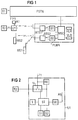
Bei der Darstellung in Fig. 1 wird davon ausgegangen, daß ein erster Teilnehmer mittels einer an einem drahtgebundenen Fernsprechnetz (Public Switched Telephone Network) PSTN angeschlossenen Teilnehmerstation T1 Informationen zu einer ebenfalls am Fernsprechnetz PSTN angeschlossenen Teilnehmer T2 eines zweiten Teilnehmers übertragen will. Die Informationen können beispielsweise ein Gespräch, Daten oder ein Faksimile sein. Der Ruf von der Teilnehmerstation T1 gelangt in bekannter Weise über das Fernsprechnetz PSTN und über die Fernsprechleitung F1 zur Anschlußeinheit A1 des zweiten Teilnehmers. Diese Anschlußeinheit A1 ist beispielsweise wie die bekannte TAE-Dose ausgebildet. Normalerweise ist an der Anschlußeinheit A1 die Teilnehmerstation T2 direkt angeschlossen. Im vorliegenden Fall ist sie jedoch über eine Umleiteinheit U1 angeschlossen. Die Umleiteinheit U1 enthält einen Umschalter, der die Fernsprechleitung F1 wahlweise mit der Teilnehmerstation T2 oder mit einer in der Umleiteinheit U1 vorgesehenen Steuereinheit verbindet. Wenn der Teilnehmer an der Teilnehmerstation T2 zu erreichen ist, ist diese über den Umschalter und die Anschlußeinheit A1 mit der Fernsprechleitung F1 verbunden. Falls der Teilnehmer jedoch unterwegs ist und über seine Mobilstation MS2 zu erreichen ist, gelangt der Ruf zur Steuereinheit in der Umleiteinheit U1. Diese stellt selbsttätig eine Verbindung zum Mobilfunknetz (Public Land Mobile Network) PLMN her und erreicht über dieses Mobilfunknetz PLMN die Mobilstation MS2.In the illustration in FIG. 1 it is assumed that a first subscriber is connected to a wired one Telephone network (Public Switched Telephone Network) PSTN connected subscriber station T1 wants to transmit information to a subscriber T2 also connected to the telephone network PSTN of a second subscriber. The information can be, for example, a conversation, data or a facsimile. The call from the subscriber station T1 arrives in a known manner via the telephone network PSTN and via the telephone line F1 to the connection unit A1 of the second subscriber. This connection unit A1 is designed, for example, like the known TAE socket. The subscriber station T2 is normally connected directly to the connection unit A1. In the present case, however, it is connected via a diversion unit U1. The diverting unit U1 contains a switch which connects the telephone line F1 either to the subscriber station T2 or to a control unit provided in the diverting unit U1. If the subscriber can be reached at the subscriber station T2, this is connected to the telephone line F1 via the changeover switch and the connection unit A1. However, if the subscriber is on the move and can be reached via his mobile station MS2, the call arrives at the control unit in the diversion unit U1. This automatically establishes a connection to the cellular network (Public Land Mobile Network) PLMN and reaches the mobile station MS2 via this cellular network PLMN.
Das Mobilfunksystem ist beispielsweise auf der Basis eines elektronischen Vermittlungssystems entsprechend dem bekannten digitalen zellularen paneuropäischen Mobilfunksystem GSM (Global System for Mobile Communication) ausgebildet. Es enthält ein Vermittlungssystem, das aus einer Mehrzahl von an dem Fernsprechnetz PSTN angeschlossenen Vermittlungsstellen MSC gebildet wird. An jeder Vermittlungsstelle MSC ist ein Funksystem angeschlossen, das aus mehreren Basisstationssteuerungen B und an diesen angeschlossenen Basisfunkstationen BTS gebildet wird, wovon in Fig. 1 nur die Basisstationssteuerungen B1 und B2 bzw. die Basisfunkstationen BTS 1 und BTS 2 dargestellt sind. An der Vermittlungsstelle MSC sind neben einem nicht dargestellten Bedien- und Wartungssystem und neben einem nicht dargestellten Geräteidentifizierungsregister eine Heimatdatei HLR und eine Besucherdatei VLR angeschlossen. In der Heimatdatei HLR sind die Daten von dort registrierten Mobilstationen gespeichert, und die Besucherdatei VLR enthält die Informationen über diejenigen Mobilstationen, die sich gerade in der jeweiligen Besucherdateifläche befinden. Ein derartiges Mobilfunksystem ist beispielsweise in einer Broschüre "D900 Mobile Communication System" SYD der Siemens AG beschrieben.The mobile radio system is designed, for example, on the basis of an electronic switching system in accordance with the well-known digital cellular pan-European mobile radio system GSM (Global System for Mobile Communication). It contains a switching system which is formed from a plurality of switching centers MSC connected to the telephone network PSTN. A radio system is connected to each switching center MSC and is formed from a plurality of base station controls B and base radio stations BTS connected to them, of which only the base station controls B1 and B2 or the base radio stations BTS 1 and BTS 2 are shown in FIG. 1. Are at the exchange MSC In addition to an operating and maintenance system (not shown) and a device identification register (not shown), a home file HLR and a visitor file VLR are connected. The data from mobile stations registered there are stored in the home file HLR, and the visitor file VLR contains the information about those mobile stations that are currently in the respective visitor file area. Such a mobile radio system is described, for example, in a brochure "D900 Mobile Communication System" SYD from Siemens AG.
Die Umleiteinheit U1 enthält neben dem Umschalter und der Steuereinheit die wesentlichen Baueinheiten einer Mobilstation, wie beispielsweise eine mit einer Antenne verbundene Sende-/Empfangseinheit und die für die Gebührenabrechnung erforderlichen Einheiten, da die Umleiteinheit U1 gegenüber dem Mobilfunksystem PLMN wie eine Mobilstation auftritt.In addition to the changeover switch and the control unit, the diversion unit U1 contains the essential components of a mobile station, such as, for example, a transmitter / receiver unit connected to an antenna and the units required for billing, since the diversion unit U1 acts like a mobile station with respect to the PLMN mobile radio system.
Bei einem von der Teilnehmerstation T1 über die Fernleitung F1 ankommenden Ruf stellt die Umleiteinheit U1, entweder sofort oder beispielsweise nach dem dritten Läuten, an der Teilnehmerstation T2 selbsttätig eine Verbindung zum Mobilfunknetz PLMN her. Beim Einschalten der Umleiteinheit U1 hat sich diese wie eine Mobilstation im Mobilfunksystem eingebucht, und ihre Daten sind in der Heimatdatei HLR gespeichert. Bei dem ankommenden Ruf stellt eine automatische Wähleinrichtung in der Steuereinheit ST über die Basisfunkstation BTS1 und die Basisstationssteuerung B1 eine Verbindung zur Vermittlungsstelle MSC her. Diese stellt fest, wo sich die Mobilstation MS2 gerade aufhält. Falls sie sich in dem Funkbereich aufhält, für den die Vermittlungsstelle MSC zuständig ist, leitet sie den Ruf über die Basisstationssteuerung B2 und die Basisfunkstation BTS2 zur Mobilstation MS2 weiter und stellt die Fernsprechverbindung her. Falls sich die Mobilstation MS2 im Funkbereich einer anderen Vermittlungsstelle aufhält, stellt die Vermittlungsstelle MSC über das Fernsprechnetz PSTN eine Verbindung zu dieser Vermittlungsstelle und über eine entsprechende Basisstationsteuerung und eine entsprechende Basisfunkstation zur Mobilstation MS2 her.In the event of a call arriving from the subscriber station T1 via the trunk line F1, the diversion unit U1 automatically establishes a connection to the mobile radio network PLMN at the subscriber station T2, either immediately or, for example, after the third ring. When the redirection unit U1 is switched on, it has logged into the mobile radio system like a mobile station, and its data are stored in the home location file HLR. For the incoming call, an automatic dialing device in the control unit ST establishes a connection to the switching center MSC via the base radio station BTS1 and the base station controller B1. This determines where the MS2 mobile station is currently located. If it is in the radio area for which the switching center MSC is responsible, it forwards the call via the base station controller B2 and the base radio station BTS2 to the mobile station MS2 and establishes the telephone connection. If the mobile station MS2 is in the radio range of another switching center, the switching center MSC establishes a connection to this switching center and via the telephone network PSTN via a corresponding base station controller and a corresponding base radio station to the mobile station MS2.
In ganz entsprechender Weise wird ein Ruf des ersten Teilnehmers umgeleitet, wenn dieser nicht von der Teilnehmerstation T1, sondern von einer dem ersten Teilnehmer zugeordneten Mobilstation MS1 ausgeht und über das Fernsprechnetz PSTN zur Teilnehmerstation T2 gelangt.A call of the first subscriber is diverted in a corresponding manner if the call does not originate from the subscriber station T1 but from a mobile station MS1 assigned to the first subscriber and reaches the subscriber station T2 via the telephone network PSTN.
Da der Verbindungsaufbau über das Mobilfunksystem PLMN eine gewisse Zeit erfordert, kann in der Zwischenzeit an die Teilnehmerstation T1 ein in der Umleiteinheit U1 gespeicherter Text, der dem dortigen Teilnehmer mitteilt, daß der gewünschte Teilnehmer über das Mobilfunksystem gerufen wird oder Pausenmusik gesendet werden.Since the connection establishment via the mobile radio system PLMN requires a certain amount of time, a text stored in the diversion unit U1 can be sent to the subscriber station T1, which informs the subscriber there that the desired subscriber is being called via the mobile radio system or pause music is being sent.
Bei der in Fig. 2 dargestellten Umleiteinheit U1 ist an der Fernsprechleitung F1 der Umschalter U angeschlossen, der die Fernsprechleitung F1 entweder mit der Teilnehmerstation T2 oder mit der Steuereinheit ST verbindet. Der Umschalter U wird durch eine Ruferkennungseinheit RE gesteuert, die, ähnlich wie bei einem Anrufbeantworter, beispielsweise nach dem dritten Läuten den Umschalter U in die gestrichelt dargestellte Position bringt und dann die Fernleitung F1 mit der Steuereinheit ST verbindet. Die Steuereinheit ST enthält eine automatische Wähleinrichtung, die in bekannter Weise ausgebildet ist. Sie stellt im vorliegenden Fall über eine Sende/Empfangseinrichtung SE und eine Antenne AN eine Verbindung zur entsprechenden Basisfunkstation BTS1 her.In the diversion unit U1 shown in FIG. 2, the switch U is connected to the telephone line F1, which connects the telephone line F1 either to the subscriber station T2 or to the control unit ST. The switch U is controlled by a call detection unit RE, which, similar to an answering machine, brings the switch U into the position shown in dashed lines, for example after the third ring, and then connects the trunk line F1 to the control unit ST. The control unit ST contains an automatic selection device which is designed in a known manner. In the present case, it establishes a connection to the corresponding base radio station BTS1 via a transceiver SE and an antenna AN.
Die Rufnummer der Mobilstation MS2 ist in einem Speicher S1 gespeichert und kann entweder fest installiert sein oder, bei einer möglichen Umleitung zu unterschiedlichen Mobilstationen, mittels einer Tastatur T eingegeben werden. Mittels der Tastatur T kann auch eingegeben werden, ob die Verbindung zur Mobilstation MS2 sofort nach dem Eintreffen eines Rufs über die Fernsprechleitung F1 erfolgen soll oder erst nach einer bestimmten Anzahl von Rufsignalen.The call number of the mobile station MS2 is stored in a memory S1 and can either be permanently installed or, in the event of a possible diversion to different mobile stations, entered using a keyboard T. The keyboard T can also be used to enter whether the connection to the mobile station MS2 is over immediately after the arrival of a call the telephone line F1 is to take place or only after a certain number of ringing signals.
Da, wie bereits erwähnt, der Verbindungsaufbau im Mobilfunksystem eine gewisse Zeit erfordert, kann zwischenzeitlich ein in einem Speicher S2 gespeicherter Text oder Pausenmusik zur Teilnehmerstation T1 übertragen werden.Since, as already mentioned, establishing the connection in the mobile radio system requires a certain amount of time, a text or pause music stored in a memory S2 can be transmitted to the subscriber station T1 in the meantime.
Gegenüber dem Mobilfunknetz PLMN stellt die Umleiteinheit U1 eine Mobilstation dar, und somit erfolgt auch die Gebührenabrechnung, wie bei einer üblichen Mobilstation zu Lasten des Inhabers der Umleiteinheit U1 und nicht zu Lasten des über die Teilnehmerstation T1 anrufenden Teilnehmers. Außer der gegebenenfalls vorhandenen zeitlichen Verzögerung beim Verbindungsaufbau und dem gegebenenfalls übertragenen entsprechenden Text ist es für den rufenden Teilnehmer unerheblich, ob der Ruf bei der Teilnehmerstation T2 oder der Mobilstation MS2 ankommt. Seitens des gerufenen Teilnehmers ist es jedoch vorteilhaft, daß er immer unter einer einzigen Telefonnummer zu erreichen ist, was insbesondere im geschäftlichen Verkehr von Bedeutung ist.Compared to the mobile radio network PLMN, the diversion unit U1 is a mobile station, and thus the billing is also carried out, as with a conventional mobile station, at the expense of the owner of the diversion unit U1 and not at the expense of the subscriber calling via the subscriber station T1. In addition to the time delay that may exist when establishing a connection and the corresponding text that may be transmitted, it is irrelevant for the calling subscriber whether the call arrives at the subscriber station T2 or the mobile station MS2. On the part of the called subscriber, however, it is advantageous that he can always be reached under a single telephone number, which is particularly important in business dealings.
Bei der Darstellung in Fig. 3 erfolgt die Umleitung des von der Teilnehmerstation T1 bzw. MS1 ankommenden Rufs zur Mobilstation MS2 unter Verwendung des Fernsprechnetzes PSTN. Hierzu ist beim Teilnehmer T2 zusätzlich eine an einer zweiten Fernsprechleitung F2 angeschlossene Anschlußeinheit A2 vorgesehen. Diese ist beispielsweise ebenfalls wie die bekannte TAE-Dose ausgebildet. Wenn ein Ruf von der Teilnehmerstation T1 über die Fernsprechleitung F1 zur Umleiteinheit U2 gelangt und der Teilnehmer den Ruf an der Teilnehmerstation T2 nicht entgegennimmt, erfolgt in der Umleiteinheit U2 über die Fernsprechleitung F2 ein Verbindungsaufbau zur Mobilstation MS2. Der Verbindungsaufbau erfolgt wie bei einem üblichen Ruf von einem am drahtgebundenen Fernsprechnetz PSTN angeschlossene Teilnehmer zu einer Mobilstation. Nach dem Wählen der Rufnummer der Mobilstation MS2 wird über das Fernsprechnetz PSTN eine Verbindung zur entsprechenden Vermittlungsstelle MSC des Mobilfunknetzes PLMN hergestellt, und der Ruf wird in der oben beschriebenen Weise zur Mobilstation MS2 weitergeleitet. Wenn der gerufene Teilnehmer über die Mobilstation MS2 erreichbar ist, wird in der Umleiteinheit U2 die Verbindung zwischen den beiden Fernsprechleitungen F1 und F2 hergestellt, so daß der Teilnehmer der Mobilstation MS2 den Ruf von der Teilnehmerstation T1 über die Umleiteinheit U2 entgegennehmen kann.In the illustration in FIG. 3, the call arriving from the subscriber station T1 or MS1 is diverted to the mobile station MS2 using the telephone network PSTN. For this purpose, a connection unit A2 connected to a second telephone line F2 is additionally provided for subscriber T2. This is also designed, for example, like the well-known TAE box. If a call from the subscriber station T1 reaches the diversion unit U2 via the telephone line F1 and the subscriber does not accept the call at the subscriber station T2, a connection is established in the diversion unit U2 via the telephone line F2 to the mobile station MS2. The connection is established as with a normal call from a subscriber connected to the wired telephone network PSTN to a mobile station. After dialing the number of the mobile station MS2 via the telephone network PSTN a connection to the corresponding switching center MSC of the cellular network PLMN is established, and the call is forwarded to the mobile station MS2 in the manner described above. If the called subscriber can be reached via the mobile station MS2, the connection between the two telephone lines F1 and F2 is established in the diversion unit U2, so that the subscriber to the mobile station MS2 can accept the call from the subscriber station T1 via the diversion unit U2.
Die in Fig. 3 dargestellte Umleiteinheit U2 unterscheidet sich von der in Fig. 2 dargestellten Umleiteinheit U1 im wesentlichen dadurch, daß die für die Verbindung zum Mobilfunknetz PLMN erforderlichen Baueinheiten durch die für eine Verbindung zum Fernsprechnetz PSTN erforderlichen Baueinheiten ersetzt sind. Gegenüber dem Fernsprechnetz PSTN stellt sich die Umleiteinheit U2 wie eine übliche Teilnehmerstation mit einer automatischen Wähleinrichtung dar. Auch hier kann während des Verbindungsaufbaus zur Mobilstation MS2 ein im Speicher S2 gespeicherter Text oder Pausenmusik zur Teilnehmerstation T1 übertragen werden. Weiterhin kann ebenfalls mittels der Tastatur T die Rufnummer der gewünschten Mobilstation MS2 in den Speicher S1 eingegeben werden. Darüber hinaus ist es möglich, mit dieser Umleiteinheit U2 auch eine beliebige Rufnummer eines am drahtgebundenen Fernsprechnetz PSTN angeschlossenen Teilnehmers einzugeben.The diverting unit U2 shown in FIG. 3 differs from the diverting unit U1 shown in FIG. 2 essentially in that the units required for the connection to the cellular network PLMN are replaced by the units required for a connection to the telephone network PSTN. Compared to the telephone network PSTN, the diverting unit U2 is like a conventional subscriber station with an automatic dialing device. Here too, text or pause music stored in the memory S2 can be transmitted to the subscriber station T1 during the establishment of the connection to the mobile station MS2. Furthermore, the call number of the desired mobile station MS2 can also be entered into the memory S1 using the keyboard T. In addition, this diversion unit U2 can also be used to enter any number of a subscriber connected to the wired telephone network PSTN.
Die Umleiteinheiten U1 und U2 können auch Teile von Nebenstellenanlagen sein, an denen weitere Teilnehmerstationen direkt angeschlossen sind. Beispielsweise kann dann mittels einer an der Umleiteinheit U2 angeschlossenen weiteren Teilnehmerstation T3 die Mobilstation MS2 gerufen werden.The diversion units U1 and U2 can also be parts of private branch exchanges to which further subscriber stations are connected directly. For example, the mobile station MS2 can then be called by means of a further subscriber station T3 connected to the diversion unit U2.
Claims (21)
dadurch gekennzeichnet,
daß die Fernsprechverbindung von der ersten Teilnehmerstation (T1, MS1) über eine am Fernsprechnetz (PSTN) angeschlossene, mit der zweiten Teilnehmerstation (T2) verbundene Umleiteinheit (U1, U2) zu einer einem Mobilfunknetz (PLMN) zugeordneten Mobilstation (MS2) umgeleitet wird.Method for rerouting a telephone connection from a first subscriber station (T1, MS1) of a first subscriber to a second subscriber, the subscriber station (T2) connected to a wired telephone network (PSTN) being assigned to the second subscriber,
characterized,
that the telephone connection is diverted from the first subscriber station (T1, MS1) via a redirection unit (U1, U2) connected to the telephone network (PSTN) and connected to the second subscriber station (T2) to a mobile station (MS2) assigned to a mobile radio network (PLMN).
dadurch gekennzeichnet,
daß die Umleitung der Fernsprechverbindung von der Umleiteinheit (U1) drahtlos zum Mobilfunknetz (PLMN) und über dieses zur Mobilstation (MS2) erfolgt.Method according to claim 1,
characterized,
that the redirection of the telephone connection from the redirection unit (U1) takes place wirelessly to the mobile radio network (PLMN) and via this to the mobile station (MS2).
dadurch gekennzeichnet,
daß die Umleitung der Fernsprechverbindung von der Umleiteinheit (U2) über das drahtgebundene Fernsprechnetz (PSTN) zum Mobilfunknetz (PLMN) und über dieses zur Mobilstation (MS2) erfolgt.Method according to claim 1,
characterized,
that the diversion of the telephone connection from the diversion unit (U2) via the wired telephone network (PSTN) to the mobile network (PLMN) and via this to the mobile station (MS2).
dadurch gekennzeichnet,
daß das Mobilfunknetz (PLMN) als Teil des an sich bekannten GSM-Mobilfunksystems ausgebildet ist.Method according to one of the preceding claims,
characterized,
that the mobile radio network (PLMN) is designed as part of the known GSM mobile radio system.
dadurch gekennzeichnet,
daß die Umleiteinheit (U1, U2) als Teil einer Nebenstellenanlage ausgebildet ist.Method according to one of the preceding claims,
characterized,
that the diversion unit (U1, U2) is designed as part of a private branch exchange.
dadurch gekennzeichnet,
daß die Umleiteinheit (U1, U2) nach einer vorgegebenen Anzahl von Rufsignalen selbsttätig die Verbindung zur Mobilstation (MS2) veranlaßt.Method according to one of the preceding claims,
characterized,
that the diversion unit (U1, U2) automatically initiates the connection to the mobile station (MS2) after a predetermined number of ring signals.
dadurch gekennzeichnet,
daß die Umleiteinheit (U1, U2) bei einem ankommenden Rufsignal sofort selbsttätig die Verbindung zur Mobilstation (MS2) veranlaßt.Method according to one of claims 1 to 5,
characterized,
that the diversion unit (U1, U2) automatically initiates the connection to the mobile station (MS2) when an incoming call signal is received.
dadurch gekennzeichnet,
daß die Umleiteinheit (U1, U2) die Verbindung zu einer Mobilstation (MS2) herstellt, deren Rufnummer in einem ersten Speicher (S1) speicherbar ist.Method according to one of the preceding claims,
characterized,
that the redirection unit (U1, U2) establishes the connection to a mobile station (MS2), the call number of which can be stored in a first memory (S1).
dadurch gekennzeichnet,
daß die Rufnummer mittels einer Tastatur (T) in den ersten Speicher (S1) eingebbar ist.A method according to claim 8,
characterized,
that the number can be entered into the first memory (S1) using a keyboard (T).
dadurch gekennzeichnet,
daß die Umleiteinheit (U1, U2) während des Herstellens der Verbindung zur Mobilstation (MS2) in einem zweiten Speicher (S2) gespeicherte Information zum anrufenden Teilnehmer (T1) überträgt.Method according to one of the preceding claims,
characterized,
that the diverting unit (U1, U2) transmits information stored in a second memory (S2) to the calling subscriber (T1) during the establishment of the connection to the mobile station (MS2).
dadurch gekennzeichnet,
daß eine am Fernsprechnetz (PSTN) angeschlossene, mit der zweiten Teilnehmerstation (T2) verbundene Umleiteinheit (U1, U2) vorgesehen ist, die eine Fernsprechverbindung von der ersten Teilnehmerstation (T1, MS1) zur zweiten Teilnehmerstation (T2) zu einer vorgegebenen Mobilstation (MS2) eines Mobilfunknetzes (PLMN) umleitet.Arrangement for rerouting a telephone connection from a first subscriber station (T1, MS1) of a first subscriber to a second subscriber, the subscriber station (T2) connected to a wired telephone network (PSTN) being assigned to the second subscriber,
characterized,
that a diverting unit (U1, U2) connected to the telephone network (PSTN) and connected to the second subscriber station (T2) is provided, which has a telephone connection from the first subscriber station (T1, MS1) to the second subscriber station (T2) to a predetermined mobile station (MS2 ) of a cellular network (PLMN).
dadurch gekennzeichnet,
daß die Umleiteinheit (U1) eine drahtlose Verbindung zum Mobilfunknetz (PLMN) herstellt.Arrangement according to claim 11,
characterized,
that the diversion unit (U1) establishes a wireless connection to the mobile radio network (PLMN).
dadurch gekennzeichnet,
daß die Umleiteinheit (U2) eine Verbindung zum Mobilfunknetz (PLMN) über das drahtgebundene Fernsprechnetz (PSTN) herstellt.Arrangement according to claim 11,
characterized,
that the diversion unit (U2) establishes a connection to the mobile radio network (PLMN) via the wired telephone network (PSTN).
dadurch gekennzeichnet,
daß das Mobilfunknetz (PLMN) als Teil des an sich bekannten GSM-Mobilfunksystems ausgebildet ist.Arrangement according to one of claims 11 to 13,
characterized,
that the mobile radio network (PLMN) is designed as part of the known GSM mobile radio system.
dadurch gekennzeichnet,
daß die Umleiteinheit (U1, U2) als Teil einer Nebenstellenanlage ausgebildet ist.Arrangement according to one of claims 11 to 14,
characterized,
that the diversion unit (U1, U2) is designed as part of a private branch exchange.
dadurch gekennzeichnet,
daß die Umleiteinheit (U1, U2) eine Ruferkennungseinheit (RE) enthält, die nach einer vorgegebenen Anzahl von Rufsignalen selbsttätig die Verbindung zur Mobilstation (MS2) veranlaßt.Arrangement according to one of claims 11 to 15,
characterized,
that the diversion unit (U1, U2) contains a call recognition unit (RE) which automatically initiates the connection to the mobile station (MS2) after a predetermined number of ring signals.
dadurch gekennzeichnet,
daß die Umleiteinheit (U1, U2) eine Ruferkennungseinheit (RE) enthält, die unmittelbar nach dem Empfang eines Rufsignals selbsttätig die Verbindung zur Mobilstation (MS2) veranlaßt.Arrangement according to one of claims 11 to 15,
characterized,
that the diversion unit (U1, U2) contains a call detection unit (RE) which automatically initiates the connection to the mobile station (MS2) immediately after receiving a call signal.
dadurch gekennzeichnet,
daß die Umleiteinheit (U1, U2) über eine Anschlußeinheit (A1, A2), die als eine an sich bekannte TAE-Dose ausgebildet ist, an der Fernsprechleitung (F1, F2) angeschlossen ist.Arrangement according to one of claims 11 to 17,
characterized,
that the diversion unit (U1, U2) is connected to the telephone line (F1, F2) via a connection unit (A1, A2), which is designed as a TAE socket known per se.
dadurch gekennzeichnet,
daß die Umleiteinheit (U1, U2) einen ersten Speicher (S1) enthält, in dem die Rufnummer der zu rufenden Mobilstation(MS2) gespeichert ist.Arrangement according to one of claims 11 to 18,
characterized,
that the diversion unit (U1, U2) contains a first memory (S1) in which the call number of the mobile station (MS2) to be called is stored.
dadurch gekennzeichnet,
daß die Umleiteinheit (U1, U2) eine Tastatur (T) enthält, mitttels der die Rufnummer der zu rufenden Mobilstation(MS2) in den ersten Speicher (S1) einspeicherbar ist.Arrangement according to claim 19,
characterized,
that the diversion unit (U1, U2) contains a keyboard (T) by means of which the call number of the mobile station (MS2) to be called can be stored in the first memory (S1).
dadurch gekennzeichnet,
daß die Umleiteinheit (U1, U2) einen zweiten Speicher (S2) enthält, in dem Information gespeichert ist, die während des Herstellens der Verbindung zur Mobilstation (MS2) zum anrufenden Teilnehmer (T1) übertragbar ist.Arrangement according to one of claims 11 to 20,
characterized,
that the diversion unit (U1, U2) contains a second memory (S2) in which information is stored which can be transferred to the calling subscriber (T1) during the establishment of the connection to the mobile station (MS2).
Applications Claiming Priority (2)
| Application Number | Priority Date | Filing Date | Title |
|---|---|---|---|
| DE4416715 | 1994-05-11 | ||
| DE4416715 | 1994-05-11 |
Publications (2)
| Publication Number | Publication Date |
|---|---|
| EP0683589A2 true EP0683589A2 (en) | 1995-11-22 |
| EP0683589A3 EP0683589A3 (en) | 1999-08-25 |
Family
ID=6517925
Family Applications (1)
| Application Number | Title | Priority Date | Filing Date |
|---|---|---|---|
| EP95106351A Ceased EP0683589A3 (en) | 1994-05-11 | 1995-04-27 | Method and apparatus for diverting a telephone connection |
Country Status (2)
| Country | Link |
|---|---|
| EP (1) | EP0683589A3 (en) |
| FI (1) | FI952291A (en) |
Cited By (3)
| Publication number | Priority date | Publication date | Assignee | Title |
|---|---|---|---|---|
| DE19631327A1 (en) * | 1996-08-02 | 1998-02-05 | Deutsche Telephonwerk Kabel | Call forwarding method for ISDN mobile terminals |
| EP0841798A2 (en) * | 1996-11-07 | 1998-05-13 | Nokia Mobile Phones Ltd. | Call diversion |
| WO1998021900A1 (en) * | 1996-11-08 | 1998-05-22 | Telefonaktiebolaget Lm Ericsson (Publ) | Method and arrangement for call forwarding in intelligent network |
Citations (5)
| Publication number | Priority date | Publication date | Assignee | Title |
|---|---|---|---|---|
| FR2533386A1 (en) * | 1982-09-21 | 1984-03-23 | Sedeca | Method of managing calls in a telephone communications network. |
| JPS61171297A (en) * | 1985-01-25 | 1986-08-01 | Fujitsu Ltd | Outside line transfer system |
| US5222123A (en) * | 1990-01-08 | 1993-06-22 | Motorola, Inc. | Registration and automatic call redirecting for cordless telephone systems |
| EP0588510A1 (en) * | 1992-08-31 | 1994-03-23 | AT&T Corp. | Call routing scheme with verification of called party presence |
| US5329578A (en) * | 1992-05-26 | 1994-07-12 | Northern Telecom Limited | Personal communication service with mobility manager |
-
1995
- 1995-04-27 EP EP95106351A patent/EP0683589A3/en not_active Ceased
- 1995-05-11 FI FI952291A patent/FI952291A/en not_active Application Discontinuation
Patent Citations (5)
| Publication number | Priority date | Publication date | Assignee | Title |
|---|---|---|---|---|
| FR2533386A1 (en) * | 1982-09-21 | 1984-03-23 | Sedeca | Method of managing calls in a telephone communications network. |
| JPS61171297A (en) * | 1985-01-25 | 1986-08-01 | Fujitsu Ltd | Outside line transfer system |
| US5222123A (en) * | 1990-01-08 | 1993-06-22 | Motorola, Inc. | Registration and automatic call redirecting for cordless telephone systems |
| US5329578A (en) * | 1992-05-26 | 1994-07-12 | Northern Telecom Limited | Personal communication service with mobility manager |
| EP0588510A1 (en) * | 1992-08-31 | 1994-03-23 | AT&T Corp. | Call routing scheme with verification of called party presence |
Non-Patent Citations (1)
| Title |
|---|
| PATENT ABSTRACTS OF JAPAN vol. 010, no. 379 (E-465), 18. Dezember 1986 & JP 61 171297 A (FUJITSU LTD), 1. August 1986 * |
Cited By (5)
| Publication number | Priority date | Publication date | Assignee | Title |
|---|---|---|---|---|
| DE19631327A1 (en) * | 1996-08-02 | 1998-02-05 | Deutsche Telephonwerk Kabel | Call forwarding method for ISDN mobile terminals |
| DE19631327B4 (en) * | 1996-08-02 | 2005-04-14 | Detewe Deutsche Telephonwerke Aktiengesellschaft & Co. Kg | Call forwarding procedure |
| EP0841798A2 (en) * | 1996-11-07 | 1998-05-13 | Nokia Mobile Phones Ltd. | Call diversion |
| EP0841798A3 (en) * | 1996-11-07 | 2002-08-28 | Nokia Corporation | Call diversion |
| WO1998021900A1 (en) * | 1996-11-08 | 1998-05-22 | Telefonaktiebolaget Lm Ericsson (Publ) | Method and arrangement for call forwarding in intelligent network |
Also Published As
| Publication number | Publication date |
|---|---|
| EP0683589A3 (en) | 1999-08-25 |
| FI952291A0 (en) | 1995-05-11 |
| FI952291A (en) | 1995-11-12 |
Similar Documents
| Publication | Publication Date | Title |
|---|---|---|
| DE69735770T2 (en) | PROVIDING A PLACE-BASED CALL FORCED IN A MOBILE TELECOMMUNICATIONS NETWORK | |
| EP0760192B1 (en) | Process for subscriber data transmission when changing the radiocommunication system | |
| DE69732519T2 (en) | Mobility management system in a personal communication system | |
| EP0893933B1 (en) | Method for controlling the routing of calls | |
| EP0896782B1 (en) | Process for integrating cordless telephone networks into cellular mobile telephone networks | |
| EP0920147A2 (en) | Method, system and network for establishing a telephonic connection towards persons in closed places, like transportation systems | |
| EP0518344A2 (en) | Connection set-up between networked mobile subscriber terminals | |
| EP0693848A2 (en) | Communication system | |
| DE4105884A1 (en) | RADIO TELEPHONE SWITCHING NETWORK | |
| EP1068744B1 (en) | Method for setting up a connection between a mobile radio network and a destination call number in a private communication network | |
| EP0676905B1 (en) | Method of establishing a connection with a subscriber over a first network with service processor, switching device and terminal | |
| DE69934498T2 (en) | HOME ZONE EXTENSION PHONE SERVICE | |
| EP0456128A2 (en) | Method for diverting or forwarding calls in telephone exchanges | |
| DE2848931C2 (en) | Circuit arrangement for subscriber stations | |
| EP0683589A2 (en) | Method and apparatus for diverting a telephone connection | |
| DE69823916T2 (en) | Method and system for access to a telecommunications network | |
| DE3843870A1 (en) | Radio network | |
| EP2237581B1 (en) | Method and assembly for transferring predefined information for mobile connections | |
| DE69733569T2 (en) | CONSTRUCTION OF A TELECOMMUNICATIONS CONNECTION | |
| AT406215B (en) | TELEPHONE SYSTEM | |
| EP0760588B1 (en) | Method and device for establishing telecommunication connections | |
| DE19628426C2 (en) | Method of linking communication networks | |
| EP1108341B1 (en) | Method and mobile communication system for controlling a connection setup | |
| DE4411119C1 (en) | Digital cellular telephone network system | |
| DE3445470A1 (en) | AUTOMATIC RADIO TELEPHONE SYSTEM WITH LOCAL TRANSMITTER RECEIVER STATIONS |
Legal Events
| Date | Code | Title | Description |
|---|---|---|---|
| PUAI | Public reference made under article 153(3) epc to a published international application that has entered the european phase |
Free format text: ORIGINAL CODE: 0009012 |
|
| AK | Designated contracting states |
Kind code of ref document: A2 Designated state(s): DE ES FR GB IT SE |
|
| PUAL | Search report despatched |
Free format text: ORIGINAL CODE: 0009013 |
|
| AK | Designated contracting states |
Kind code of ref document: A3 Designated state(s): DE ES FR GB IT SE |
|
| RIC1 | Information provided on ipc code assigned before grant |
Free format text: 6H 04M 3/54 A, 6H 04Q 7/22 B, 6H 04M 1/65 B, 6H 04Q 7/38 B |
|
| 17P | Request for examination filed |
Effective date: 20000224 |
|
| 17Q | First examination report despatched |
Effective date: 20001127 |
|
| GRAG | Despatch of communication of intention to grant |
Free format text: ORIGINAL CODE: EPIDOS AGRA |
|
| STAA | Information on the status of an ep patent application or granted ep patent |
Free format text: STATUS: THE APPLICATION HAS BEEN REFUSED |
|
| 18R | Application refused |
Effective date: 20020826 |