EP0685572A2 - Coated hard-alloy blade member - Google Patents
Coated hard-alloy blade member Download PDFInfo
- Publication number
- EP0685572A2 EP0685572A2 EP95103339A EP95103339A EP0685572A2 EP 0685572 A2 EP0685572 A2 EP 0685572A2 EP 95103339 A EP95103339 A EP 95103339A EP 95103339 A EP95103339 A EP 95103339A EP 0685572 A2 EP0685572 A2 EP 0685572A2
- Authority
- EP
- European Patent Office
- Prior art keywords
- ticn
- coated
- weight
- blade member
- cutting
- Prior art date
- Legal status (The legal status is an assumption and is not a legal conclusion. Google has not performed a legal analysis and makes no representation as to the accuracy of the status listed.)
- Granted
Links
Images
Classifications
-
- C—CHEMISTRY; METALLURGY
- C23—COATING METALLIC MATERIAL; COATING MATERIAL WITH METALLIC MATERIAL; CHEMICAL SURFACE TREATMENT; DIFFUSION TREATMENT OF METALLIC MATERIAL; COATING BY VACUUM EVAPORATION, BY SPUTTERING, BY ION IMPLANTATION OR BY CHEMICAL VAPOUR DEPOSITION, IN GENERAL; INHIBITING CORROSION OF METALLIC MATERIAL OR INCRUSTATION IN GENERAL
- C23C—COATING METALLIC MATERIAL; COATING MATERIAL WITH METALLIC MATERIAL; SURFACE TREATMENT OF METALLIC MATERIAL BY DIFFUSION INTO THE SURFACE, BY CHEMICAL CONVERSION OR SUBSTITUTION; COATING BY VACUUM EVAPORATION, BY SPUTTERING, BY ION IMPLANTATION OR BY CHEMICAL VAPOUR DEPOSITION, IN GENERAL
- C23C16/00—Chemical coating by decomposition of gaseous compounds, without leaving reaction products of surface material in the coating, i.e. chemical vapour deposition [CVD] processes
- C23C16/22—Chemical coating by decomposition of gaseous compounds, without leaving reaction products of surface material in the coating, i.e. chemical vapour deposition [CVD] processes characterised by the deposition of inorganic material, other than metallic material
- C23C16/30—Deposition of compounds, mixtures or solid solutions, e.g. borides, carbides, nitrides
- C23C16/36—Carbonitrides
-
- C—CHEMISTRY; METALLURGY
- C23—COATING METALLIC MATERIAL; COATING MATERIAL WITH METALLIC MATERIAL; CHEMICAL SURFACE TREATMENT; DIFFUSION TREATMENT OF METALLIC MATERIAL; COATING BY VACUUM EVAPORATION, BY SPUTTERING, BY ION IMPLANTATION OR BY CHEMICAL VAPOUR DEPOSITION, IN GENERAL; INHIBITING CORROSION OF METALLIC MATERIAL OR INCRUSTATION IN GENERAL
- C23C—COATING METALLIC MATERIAL; COATING MATERIAL WITH METALLIC MATERIAL; SURFACE TREATMENT OF METALLIC MATERIAL BY DIFFUSION INTO THE SURFACE, BY CHEMICAL CONVERSION OR SUBSTITUTION; COATING BY VACUUM EVAPORATION, BY SPUTTERING, BY ION IMPLANTATION OR BY CHEMICAL VAPOUR DEPOSITION, IN GENERAL
- C23C16/00—Chemical coating by decomposition of gaseous compounds, without leaving reaction products of surface material in the coating, i.e. chemical vapour deposition [CVD] processes
- C23C16/22—Chemical coating by decomposition of gaseous compounds, without leaving reaction products of surface material in the coating, i.e. chemical vapour deposition [CVD] processes characterised by the deposition of inorganic material, other than metallic material
- C23C16/30—Deposition of compounds, mixtures or solid solutions, e.g. borides, carbides, nitrides
- C23C16/40—Oxides
- C23C16/403—Oxides of aluminium, magnesium or beryllium
-
- C—CHEMISTRY; METALLURGY
- C23—COATING METALLIC MATERIAL; COATING MATERIAL WITH METALLIC MATERIAL; CHEMICAL SURFACE TREATMENT; DIFFUSION TREATMENT OF METALLIC MATERIAL; COATING BY VACUUM EVAPORATION, BY SPUTTERING, BY ION IMPLANTATION OR BY CHEMICAL VAPOUR DEPOSITION, IN GENERAL; INHIBITING CORROSION OF METALLIC MATERIAL OR INCRUSTATION IN GENERAL
- C23C—COATING METALLIC MATERIAL; COATING MATERIAL WITH METALLIC MATERIAL; SURFACE TREATMENT OF METALLIC MATERIAL BY DIFFUSION INTO THE SURFACE, BY CHEMICAL CONVERSION OR SUBSTITUTION; COATING BY VACUUM EVAPORATION, BY SPUTTERING, BY ION IMPLANTATION OR BY CHEMICAL VAPOUR DEPOSITION, IN GENERAL
- C23C30/00—Coating with metallic material characterised only by the composition of the metallic material, i.e. not characterised by the coating process
- C23C30/005—Coating with metallic material characterised only by the composition of the metallic material, i.e. not characterised by the coating process on hard metal substrates
-
- Y—GENERAL TAGGING OF NEW TECHNOLOGICAL DEVELOPMENTS; GENERAL TAGGING OF CROSS-SECTIONAL TECHNOLOGIES SPANNING OVER SEVERAL SECTIONS OF THE IPC; TECHNICAL SUBJECTS COVERED BY FORMER USPC CROSS-REFERENCE ART COLLECTIONS [XRACs] AND DIGESTS
- Y10—TECHNICAL SUBJECTS COVERED BY FORMER USPC
- Y10T—TECHNICAL SUBJECTS COVERED BY FORMER US CLASSIFICATION
- Y10T428/00—Stock material or miscellaneous articles
- Y10T428/12—All metal or with adjacent metals
- Y10T428/12014—All metal or with adjacent metals having metal particles
- Y10T428/12028—Composite; i.e., plural, adjacent, spatially distinct metal components [e.g., layers, etc.]
- Y10T428/12049—Nonmetal component
-
- Y—GENERAL TAGGING OF NEW TECHNOLOGICAL DEVELOPMENTS; GENERAL TAGGING OF CROSS-SECTIONAL TECHNOLOGIES SPANNING OVER SEVERAL SECTIONS OF THE IPC; TECHNICAL SUBJECTS COVERED BY FORMER USPC CROSS-REFERENCE ART COLLECTIONS [XRACs] AND DIGESTS
- Y10—TECHNICAL SUBJECTS COVERED BY FORMER USPC
- Y10T—TECHNICAL SUBJECTS COVERED BY FORMER US CLASSIFICATION
- Y10T428/00—Stock material or miscellaneous articles
- Y10T428/24—Structurally defined web or sheet [e.g., overall dimension, etc.]
- Y10T428/24942—Structurally defined web or sheet [e.g., overall dimension, etc.] including components having same physical characteristic in differing degree
Definitions
- the present invention relates to coated hard alloy blade members or cutting tools having exceptional steel and cast iron cutting ability for both continuous and interrupted cutting.
- a coated cemented carbide cutting tool made by using either chemical vapor deposition or physical vapor deposition to apply a coating layer of an average thickness of 0.5-20 ⁇ m comprised of either multiple layers or a single layer of one or more of titanium carbide, titanium nitride, titanium carbonitride, titanium oxycarbide titanium oxycarbonitride, and aluminum oxide (hereafter indicated by TiC, TiN, TiCN, TiCO, TiCNO, and Al2O3) onto a WC-based cemented carbide substrate for cutting steel or cast iron has been widely recognized.
- Japanese Patent Application No. 2-156663 shows that a coated cemented carbide having a coating layer wherein the TiC has a strong (111) orientation and the Al2O3 is of the ⁇ -type has the features that there is less spalling of the coating layer and has a long life.
- Japanese Patent Application No. 50-16171 discloses that coating is possible with the use of organic gas for a portion of the reaction gas, at a relatively low temperature.
- the crystal structure of the coating layer is not described, and furthermore, the crystal structure may have a granular form, or the crystals may grow in one direction (elongated crystals) depending on the coating conditions.
- the coating layer is made up of only TiCN, and Al2O3 is not disclosed. Additionally, this TiCN had a low bonding strength with the substrate.
- the coated hard alloy blade member in accordance with the present invention comprises a substrate formed of a hard alloy selected from the group consisting of a WC-based cemented carbide and a TiCN-based cermet, and a hard coating deposited on said substrate, the hard coating including an inner layer of TiCN having unilaterally grown crystals of an elongated shape and an outer layer of Al2O3 having a crystal form ⁇ or ⁇ + ⁇ wherein ⁇ > ⁇ .
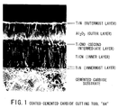
- FIG. 1 is a photograph of a coated cemented carbide blade member in accordance with the present invention as taken by a scanning electron microscope.
- coated hard alloy blade member or cutting tool in accordance with the present invention will now be described in detail.
- the coated hard alloy blade member in accordance with the present invention comprises a substrate formed of a hard alloy selected from the group consisting of a WC-based cemented carbide and a TiCN-based cermet, and a hard coating deposited on said substrate, the hard coating including an inner layer of TiCN having unilaterally grown crystals of an elongated shape and an outer layer of Al2O3 having a crystal form ⁇ or ⁇ + ⁇ wherein ⁇ > ⁇ .
- the substrate it is first necessary to coat the substrate with elongated crystal TiCN having high bonding strength. If the conditions are such that, for example, during the coating of the TiCN, the percentages of the respective volumes are: TiCl4: 1-10%, CH3CN: 0.1-5%, N2: 0-35%, H2: the rest, the reaction temperature is 800-950 °C, the pressure is 30-500 Torr, and furthermore, the CH3CN gas is decreased to 0.01-0.1% at the beginning of the coating as a first coating reaction for 1-120 minutes, then the CH3CN gas is increased to 0.1-1% as a second coating reaction, then elongated crystal TiCN having high bonding strength can be obtained.
- the thickness of the TiCN coating layer should preferably be 1-20 ⁇ m. This is because at less than 1 ⁇ m the wear resistance worsens, and at more than 20 ⁇ m the fracture resistance worsens.
- the (200) plane component of the X-ray diffraction pattern of the TiCN becomes weaker than the (111) and (220) plane components, the bonding strength with the Al2O3 in the upper layer which has ⁇ as its main form increases, and the wear resistance goes up.
- Al2O3 of ⁇ form or ⁇ + ⁇ form wherein form ⁇ > ⁇ is coated.
- the conditions should be such that, for example, the reaction gas is made up of the following volume percentages in the first 1-120 minutes: AlCl3: 1-20%, HCl: 1-20% and/or H2S: 0.05-5% as needed, and H2: the rest, and a first reaction be performed, then afterwards, a second reaction is performed in which AlCl3: 1-20%, CO2: 0.5-30%, HCl: 1-20% and/or H2S: 0.05-5% as needed, and H2: the rest, with the conditions of a reaction temperature of 850-1000 °C and pressure of 30-500 Torr.
- the thickness of this Al2O3 coating layer should preferably be 0.1-10 ⁇ m. At less than 0.1 ⁇ m the wear resistance worsens, while at over 10 ⁇ m the fracturing resistance worsens.
- the combined thickness of the first TiCN layer and the second Al2O3 layer should preferably be 2-30 ⁇ m.
- the K ratio of the ⁇ + ⁇ Al2O3 of the present invention uses a peak from Cu- ⁇ X-ray diffraction, and is determined the following equation, wherein if ⁇ > ⁇ then the ⁇ ratio is over 50%.
- either one or both of TiN or TiCN may be coated on the outer Al2O3 layer.
- the reason for this coating layer is to discriminate between areas of use, and a thickness of 0.1-2 ⁇ m is preferable.
- either one or more of TiN, TiC, or TiCN (granular form) may be coated underneath the inner TiCN layer. By coating with this innermost layer, the bonding strength of the elongated crystal TiCN improves and the wear resistance improves. The most preferable thickness for this coating is 0.1-5 ⁇ m.
- first intermediate layer Between the inner TiCN layer and the outer Al2O3 layer, either one or more of TiN, TiC, or TiCN (granular form) may be coated as a first intermediate layer.
- This first intermediate layer improves the wear resistance during low speed cutting. However, during high speed cutting, it worsens the wear resistance.
- the most preferable thickness for this first intermediate layer is 1-7 ⁇ m.
- TiCO Between the inner TiCN layer and the outer Al2O3 layer, either one or both of TiCO, TiCNO is coated as a second intermediate layer.
- This second intermediate layer increases the bonding strength between the elongated crystal TiCN and the ⁇ or ⁇ + ⁇ form Al2O3.
- the most preferable thickness of this second intermediate layer is 0. 1-2 ⁇ m.
- the inner layer coated with elongated crystal TiCN may be divided by one or more TiN layers to define a divided TiCN layer. This divided TiCN layer is less susceptible to chipping, and the fracture resistance improves.
- the most preferable composition of the WC-based cemented carbide substrate is, by the percentage of weight, as follows: Co: 4-12% Ti: 0-7% Ta: 0-7% Nb: 0-4% Cr: 0-2% N: 0-1% W and C: the rest Unavoidable impurities such as O, Fe, Ni, and Mo are also included.
- the cemented carbide for lathe turning of steel, it is preferable that the cemented carbide be such that the amount of Co or Co + Cr in the surface portion (the highest value from the surface to within 100 ⁇ m) be 1.5 to 5 times the amount in the interior (1 mm from the surface), and for lathe turning of cast iron, it is preferable that there is no enrichment of the Co or Co + Cr, and that the amount of Co or Co + Cr be small. Furthermore, in the case of steel milling, cemented carbide in which there has been no enrichment of the Co or Co + Cr, and the amount of Co or Co + Cr is large, is preferable.
- the most preferable composition of the TiCN-based cermet substrate is, by the percentage of weight, as follows: Co: 2-14% Ni: 2-12% Ta: 2-20% Nb: 0.1-10% W: 5-30% Mo: 5-20% N: 2-8% Ti and C: the rest Cr, V, Zr, Hf: 0-5% Unavoidable impurities such as O and Fe are included.
- the substrate surface layer (the largest value within 100 ⁇ m of the surface) should be 5% or more harder than the interior (1 mm from the surface) or there should be no difference between the hardnesses of the surface layer and the interior.
- Tables 4-7 The results of the above tests are shown in Tables 4-7. As is able to be seen from Tables 4-7, all of the coated cemented carbide cutting tools and coated cermet cutting tools of the present invention demonstrate the properties that it is difficult to fracture or chip the cutting blades and spalling of the coating layers is rare, in addition to exhibiting superior wear and fracture resistance.
- Example 1 Using the same cemented carbide substrates A-E, E' and cermet substrates F and G as Example 1, under the same coating conditions as shown in Tables 3(a) and 3(b) in Example 1, by forming coating layers of the composition, crystal structures, and average thicknesses shown in Tables 8 and 9, the coated cemented carbide cutting tools of the present invention 29-40, the coated cermet cutting tools of the present invention 41 and 42, the coated cemented carbide cutting tools of the prior art 29-40. and the coated cermet cutting tools 41 and 42 of the prior art were produced.
- a mild steel continuous cutting test was performed under the following conditions, Workpiece: mild steel round bar Cutting Speed: 300 m/min Feed: 0.27 mm/rev Depth of Cut: 1 mm Cutting Time: 20 min and an appraisal identical to that of Example 1 was made. Furthermore, an interrupted cutting test was performed under the following conditions, Workpiece: mild steel round bar with groove Cutting Speed: 280 m/min Feed: 0.22 mm/rev Depth of Cut: 1 mm Cutting Time: 20 min and an appraisal identical to that of Example 1 was made.
- Example 1 Using the same cemented carbide substrates A-E, E' and cermet substrates F and G as Example 1, under the same coating conditions as shown in Tables 3(a) and 3(b) in Example 1, by forming coating layers of the composition, crystal structures, and average thickness shown in Tables 10-13, the coated cemented carbide cutting tools of the present invention 43-54 and 57-68, the coated cermet cutting tools of the present invention 55, 56, 69 and 70, the coated cemented carbide cutting tools of the prior art 43-54 and 57-68, and the coated cermet cutting tools 55, 56, 69 and 70 of the prior art were produced.
- Figure 1 shows a photograph of the surface layer of the coated cemented carbide cutting tool of the present invention as taken by a scanning electron microscope.
- a mild steel continuous cutting test was performed under the following conditions, Workpiece: mild steel round bar Cutting Speed: 330 m/min Feed: 0.23 mm/rev Depth of Cut: 1 mm Cutting Time: 20 min and an appraisal identical to that of Example 1 was made. Furthermore, an interrupted cutting test was performed under the following conditions, Workpiece: mild steel round bar with groove Cutting Speed: 310 m/min Feed: 0.18 mm/rev Depth of Cut: 1 mm Cutting Time: 20 min and an appraisal identical to that of Example 1 was made.
- Example 1 Using the same cemented carbide substrates A-E, E' and cermet substrates F and G as Example 1, under the same coating conditions as shown in Tables 3(a) and 3(b) in Example 1, by forming coating layers of the composition, crystal structures, and average thicknesses shown in Tables 14-17, the coated cemented carbide cutting tools of the present invention 71-82 and 85-96, the coated cermet cutting tools of the present invention 83, 84, 97 and 98, the coated cemented carbide cutting tools of the prior art 71-82 and 85-96, and the coated cermet cutting tools 83, 84, 97 and 98 of the prior art were produced.
- a mild steel continuous cutting test was performed under the following conditions, Workpiece: mild steel round bar Cutting Speed: 310 m/min Feed: 0.26 mm/rev Depth of Cut: 1 mm Cutting Time: 20 min and an appraisal identical to that of Example 1 was made. Furthermore, an interrupted cutting test was performed under the following conditions, Workpiece: mild steel round bar with groove Cutting Speed: 290 m/min Feed: 0.21 mm/rev Depth of Cut: 1 mm Cutting Time: 20 min and an appraisal identical to that of Example 1 was made.
- Example 1 Using the same cemented carbide substrates A-E, E' and cermet substrates F and G as Example 1, under the same coating conditions as shown in Tables 3(a) and 3(b) in Example 1, by forming coating layers of the composition, crystal structures, and average thicknesses shown in Tables 18-21, the coated cemented carbide cutting tools of the present invention 99-112 and 122-126, the coated cermet cutting tools of the present invention 113-121, the coated cemented carbide cutting tools of the prior art 99-112 and 122-126, and the coated cermet cutting tools 113-121 of the prior art were produced.
- a mild steel continuous cutting test was performed under the following conditions, Workpiece: mild steel round bar Cutting Speed: 340 m/min Feed: 0.22 mm/rev Depth of Cut: 1 mm Cutting Time: 20 min and an appraisal identical to that of Example 1 was made. Furthermore, an interrupted cutting test was performed under the following conditions, Workpiece: mild steel round bar with groove Cutting Speed: 320 m/min Feed: 0.17 mm/rev Depth of Cut: 1 mm Cutting Time: 20 min and an appraisal identical to that of Example 1 was made.
Abstract
Description
- The present invention relates to coated hard alloy blade members or cutting tools having exceptional steel and cast iron cutting ability for both continuous and interrupted cutting.
- Until now, the use of a coated cemented carbide cutting tool made by using either chemical vapor deposition or physical vapor deposition to apply a coating layer of an average thickness of 0.5-20 µm comprised of either multiple layers or a single layer of one or more of titanium carbide, titanium nitride, titanium carbonitride, titanium oxycarbide titanium oxycarbonitride, and aluminum oxide (hereafter indicated by TiC, TiN, TiCN, TiCO, TiCNO, and Al₂O₃) onto a WC-based cemented carbide substrate for cutting steel or cast iron has been widely recognized.
- The most important technological advance that led to the wide usage of the above-mentioned coated cemented carbide cutting tool was, as described in Japanese Patent Application No. 52-46347 and Japanese Patent Application No. 51-27171, the development of an exceptionally tough substrate wherein the surface layer of a WC-based cemented carbide substrate included a lot of Co, a binder metal, in comparison with the interior, whereby the fracture resistance of the coated cemented carbide cutting tool rapidly improved.
- In addition, as disclosed in Japanese Patent Application No. 52-156303 and Japanese Patent Application No. 54-83745, the confirmation that, by sintering the WC-based cemented carbide containing nitrogen in a denitrifying atmosphere such as a vacuum, the surface layer of the WC-based cemented carbide substrate can be made from WC-Co which does not include a hard dispersed phase having a B-1 type crystal structure, whereby it is possible to cheaply produce WC-based cemented carbide having more Co in its surface layer than in the interior, was also important.
- Concerning the advancement of the coating layer, coated cemented carbides having coating layers wherein the X-ray diffraction peaks of the Ti compounds such as TiC, TiN, and TiCN have a strong (200) orientation and the Al₂O₃ has an α-type crystal structure such as described in Japanese Patent Application No. 61-231416 and coated cemented carbides having coating layers wherein the X-ray diffraction peaks of the Ti compounds such as TiC, TiN, and TiCN have a strong (220) orientation and the Al₂O₃ has a κ-type crystal structure such as described in Japanese Patent Application No. 62-29263 have little variation in the tool life.
- Furthermore, Japanese Patent Application No. 2-156663 shows that a coated cemented carbide having a coating layer wherein the TiC has a strong (111) orientation and the Al₂O₃ is of the κ-type has the features that there is less spalling of the coating layer and has a long life.
- However, since the Ti compounds such as TiC of Japanese Patent Application No. 61-231416, Japanese Patent Application No. 62-29263, and Japanese Patent Application No. 2-156663 are coated by the normal CVD method, the crystal structure is in a granular form identical to the coating layers of the past, and the cutting ability was not always satisfactory.
- Additionally, Japanese Patent Application No. 50-16171 discloses that coating is possible with the use of organic gas for a portion of the reaction gas, at a relatively low temperature. In this patent, the crystal structure of the coating layer is not described, and furthermore, the crystal structure may have a granular form, or the crystals may grow in one direction (elongated crystals) depending on the coating conditions. Moreover, in the references given in this patent, the coating layer is made up of only TiCN, and Al₂O₃ is not disclosed. Additionally, this TiCN had a low bonding strength with the substrate.
- In recent years cutting technology has shown remarkable progress towards unmanned, high speed processes. Therefore, tools which are highly resistant to wear and fracturing are required. Consequently, the present inventors conducted research to develop a coated cemented carbide cutting tool having cutting ability of a higher level.
- It was discovered that by coating the surface of a WC-based cemented carbide substrate and a TiCN-based cermet substrate with TiCN having crystals growing in one direction (elongated crystals) as an inner layer, and coating with Al₂O₃ having a crystal structure κ or κ + α wherein κ > α as an outer layer, remarkable steel and cast iron cutting ability was shown for both continuous cutting and interrupted cutting.
- Thus, the coated hard alloy blade member in accordance with the present invention comprises a substrate formed of a hard alloy selected from the group consisting of a WC-based cemented carbide and a TiCN-based cermet, and a hard coating deposited on said substrate, the hard coating including an inner layer of TiCN having unilaterally grown crystals of an elongated shape and an outer layer of Al₂O₃ having a crystal form κ or κ + α wherein κ > α.
- FIG. 1 is a photograph of a coated cemented carbide blade member in accordance with the present invention as taken by a scanning electron microscope.
- The coated hard alloy blade member or cutting tool in accordance with the present invention will now be described in detail.
- As mentioned before, the coated hard alloy blade member in accordance with the present invention comprises a substrate formed of a hard alloy selected from the group consisting of a WC-based cemented carbide and a TiCN-based cermet, and a hard coating deposited on said substrate, the hard coating including an inner layer of TiCN having unilaterally grown crystals of an elongated shape and an outer layer of Al₂O₃ having a crystal form κ or κ + α wherein κ > α.
- In order to practicalize the present invention, it is first necessary to coat the substrate with elongated crystal TiCN having high bonding strength. If the conditions are such that, for example, during the coating of the TiCN, the percentages of the respective volumes are: TiCl4: 1-10%, CH₃CN: 0.1-5%, N₂: 0-35%, H₂: the rest, the reaction temperature is 800-950 °C, the pressure is 30-500 Torr, and furthermore, the CH₃CN gas is decreased to 0.01-0.1% at the beginning of the coating as a first coating reaction for 1-120 minutes, then the CH₃CN gas is increased to 0.1-1% as a second coating reaction, then elongated crystal TiCN having high bonding strength can be obtained. The thickness of the TiCN coating layer should preferably be 1-20 µm. This is because at less than 1 µm the wear resistance worsens, and at more than 20 µm the fracture resistance worsens.
- Furthermore, during the coating of the TiCN, if the reaction temperature or the amount of CH₃CN is increased, the (200) plane component of the X-ray diffraction pattern of the TiCN becomes weaker than the (111) and (220) plane components, the bonding strength with the Al₂O₃ in the upper layer which has κ as its main form increases, and the wear resistance goes up.
- Next, Al₂O₃ of κ form or κ + α form wherein form κ > α is coated. For coating Al₂O₃ which has κ as its principal form, the conditions should be such that, for example, the reaction gas is made up of the following volume percentages in the first 1-120 minutes: AlCl₃: 1-20%, HCl: 1-20% and/or H₂S: 0.05-5% as needed, and H₂: the rest, and a first reaction be performed, then afterwards, a second reaction is performed in which AlCl₃: 1-20%, CO₂: 0.5-30%, HCl: 1-20% and/or H₂S: 0.05-5% as needed, and H₂: the rest, with the conditions of a reaction temperature of 850-1000 °C and pressure of 30-500 Torr.
- The thickness of this Al₂O₃ coating layer should preferably be 0.1-10 µm. At less than 0.1 µm the wear resistance worsens, while at over 10 µm the fracturing resistance worsens.
- The combined thickness of the first TiCN layer and the second Al₂O₃ layer should preferably be 2-30 µm.
- The K ratio of the κ + α Al₂O₃ of the present invention uses a peak from Cu-κα X-ray diffraction, and is determined the following equation, wherein if κ > α then the κ ratio is over 50%.

wherein - Iκ2.79:
- The height of the X-ray diffraction peak for ASTM No. 4-0878 with a plane index spacing of d = 2.79
- Iκ1.43:
- The height of the X-ray diffraction peak for ASTM No. 4-0878 with a plane index spacing of d = 1.43
- Iα2.085:
- The height of the X-ray diffraction peak for ASTM No. 10-173 with a plane index spacing of d = 2.085 (the (113) plane)
- Iα1.601:
- The height of the X-ray diffraction peak for ASTM No. 10-173 with a plane index spacing of d = 1.601 (the (116) plane)
- As further modified embodiments of the present invention, the following are included.
(1) As an outermost layer, either one or both of TiN or TiCN may be coated on the outer Al₂O₃ layer. The reason for this coating layer is to discriminate between areas of use, and a thickness of 0.1-2 µm is preferable.
(2) As an innermost layer, either one or more of TiN, TiC, or TiCN (granular form) may be coated underneath the inner TiCN layer. By coating with this innermost layer, the bonding strength of the elongated crystal TiCN improves and the wear resistance improves. The most preferable thickness for this coating is 0.1-5 µm.
(3) Between the inner TiCN layer and the outer Al₂O₃ layer, either one or more of TiN, TiC, or TiCN (granular form) may be coated as a first intermediate layer. This first intermediate layer improves the wear resistance during low speed cutting. However, during high speed cutting, it worsens the wear resistance. The most preferable thickness for this first intermediate layer is 1-7 µm.
(4) Between the inner TiCN layer and the outer Al₂O₃ layer, either one or both of TiCO, TiCNO is coated as a second intermediate layer. This second intermediate layer increases the bonding strength between the elongated crystal TiCN and the κ or κ + α form Al₂O₃. The most preferable thickness of this second intermediate layer is 0. 1-2µm.
(5) It is possible to combine the above-mentioned (1)-(4) as appropriate.
(6) The inner layer coated with elongated crystal TiCN may be divided by one or more TiN layers to define a divided TiCN layer. This divided TiCN layer is less susceptible to chipping, and the fracture resistance improves.
(7) With the divided elongated TiCN described above and the κ or κ + α form Al₂O₃, it is possible to coat with an outermost layer of one or both of TiN or TiCN as in (1) above, coat with an innermost layer of one or more of TiN, TiC, or TiCN as in (2) above, coat with a first intermediate layer of one or more of TiC, TiN, or TiCN as in (3) above, coat with a second intermediate layer of one or both of TiCO or TiCNO as in (4) above, or to take a combination of them.
(8) The most preferable composition of the WC-based cemented carbide substrate is, by the percentage of weight, as follows:Co: 4-12% Ti: 0-7% Ta: 0-7% Nb: 0-4% Cr: 0-2% N: 0-1% W and C: the rest
(9) For the WC-based cemented carbide of the present invention, for lathe turning of steel, it is preferable that the cemented carbide be such that the amount of Co or Co + Cr in the surface portion (the highest value from the surface to within 100 µm) be 1.5 to 5 times the amount in the interior (1 mm from the surface), and for lathe turning of cast iron, it is preferable that there is no enrichment of the Co or Co + Cr, and that the amount of Co or Co + Cr be small. Furthermore, in the case of steel milling, cemented carbide in which there has been no enrichment of the Co or Co + Cr, and the amount of Co or Co + Cr is large, is preferable.
(10) The most preferable composition of the TiCN-based cermet substrate is, by the percentage of weight, as follows:Co: 2-14% Ni: 2-12% Ta: 2-20% Nb: 0.1-10% W: 5-30% Mo: 5-20% N: 2-8% Ti and C: the rest Cr, V, Zr, Hf: 0-5%
(11) In the TiCN-based cermet of the present invention, the substrate surface layer (the largest value within 100 µm of the surface) should be 5% or more harder than the interior (1 mm from the surface) or there should be no difference between the hardnesses of the surface layer and the interior. - The present invention will be explained in more detail by way of the following examples.
- As the raw materials, medium grain WC powder having an average particle size of 3 µm, 5 µm coarse grain WC powder, 1.5 µm (Ti, W)C (by weight ratio, TiC/WC = 30/70) powder 1.2 µm (Ti, W)(C, N) (TiC/TiN/WC = 24/20/56) powder, 1.5 µm Ti(C, N) (TiC/TiN = 50/50) powder, 1.6 µm (Ta, Nb)C (TaC/NbC=90/10) powder, 1.8 µm TaC powder, 1.1 µm Mo₂C powder, 1.7 µm ZrC powder, 1.8 µm Cr₃C₂ powder, 2.0 µm Ni powder, 2.2 µm NiAl (Al: 31% by weight) powder, and 1.2 µm Co powder were prepared, then these raw material powders were blended in the compositions shown in Table 1 and wet-mixed in a ball mill for 72 hours. After drying, they were press-shaped into green compacts of the form of ISO CNMG 120408 (cemented carbide substrates A-D, cermet substrates F-G) and SEEN 42 AFTN 1 (cemented carbide substrates E and E'), then these green compacts were sintered under the conditions described in Table 1, thus resulting in the production of cemented carbide substrates A-E, E' and cermet substrates F-G.
- Experimental values taken at over 1 mm from the surface of the sintered compacts of the cemented carbide substrates A-E, E' and the cermet substrates F-G are as shown in Table 2.
- Furthermore, in the case of the above cemented carbide substrate B, after maintenance in an atmosphere of CH₄ gas at 100 torr and a temperature of 1400 °C for 1 hour, a gradually cooling carburizing procedure was run, then, by removing the carbon and Co attached to the substrate surface using acid and barrel polishing, a Co-rich region 40 µm deep was formed in the substrate surface layer wherein, at a position 10 µm from the surface the maximum Co content was 15% by weight.
- Additionally, in the case of cemented carbide substrates A and D above, while sintered, a Co-rich region 20 µm deep was formed wherein, at a position 15 µm from the surface, the maximum Co content was 11% and 9% by weight, respectively, and in the remaining cemented carbide substrates C, E and E', no Co-rich region was formed, and they had similar compositions over their entirety.
- In the above cermet substrates F and G, in the sintered state, a surface layer harder than the interior existed. The hardnesses at the surface and 1 mm below the surface for the cermet substrates F and G are shown in Table 2.
- Next, after honing the surfaces of the cemented carbide substrates A-E, E' and cermet substrates F and G, by forming coating layers under the special coating conditions shown in Tables 3(a) and 3(b) and having the compositions, crystal structures, orientation of TiCN (shown, starting from the left, in the order of the intensity of the corresponding X-ray diffraction peak) and average thicknesses shown in Table 4 by using a chemical vapor deposition apparatus, the coated cemented carbide cutting tools of the present invention 1-12 and 15-26, the coated cermet cutting tools of the present invention 13, 14, 27, and 28, the coated cemented carbide cutting tools of the prior art 1-12 and 15-26, and the coated cermet cutting tools 13, 14, 27, and 28 of the prior art were produced.
- Then, for the coated cemented carbide cutting tools of the present invention 1-10 and 15-24, and the coated cemented carbide cutting tools of the prior art 1-10 and 15-24, a mild steel continuous cutting test was performed under the following conditions,
Workpiece: mild steel round bar
Cutting Speed: 270 m/min
Feed: 0.25 mm/rev
Depth of Cut: 2 mm
Cutting Time: 30 min
in which a determination was made whether or not the cutting failed due to tears made in the workpiece because of chipping of the cutting blade or spalling of the coating layer. Then, for those which were able to cut for the set period of time, the amount of flank wear was measured. Furthermore, an interrupted cutting test was performed under the following conditions,
Workpiece: mild steel round bar with groove
Cutting Speed: 250 m/min
Feed: 0.25 mm/rev
Depth of Cut: 1.5 mm
Cutting Time: 40 min
in which a determination was made whether or not the cutting failed due to trouble such as fracturing or chipping of the cutting blade. Then, for those which were able to cut for the set period of time, the amount of flank wear was measured. - For the coated cemented carbide cutting tools of the present invention 11, 12, 25 and 26, and the coated cemented carbide cutting tools of the prior art 11, 12, 25 and 26, a mild steel milling test was performed under the following conditions,
Workpiece: mild steel square block
Cutting Speed: 250 m/min
Feed: 0.35 mm/tooth
Depth of Cut: 2.5 mm
Cutting Time: 40 min
in which a determination was made whether or not the milling failed due to trouble such as chipping of the cutting blade. Then, for those which were able to cut for the set period of time, the amount of flank wear was measured. - For the coated cermet cutting tools of the present invention 13, 14, 27 and 28, and the coated cermet cutting tools of the prior art 13, 14, 27 and 28, a mild steel continuous cutting test was performed under the following conditions,
Workpiece: mild steel round bar
Cutting Speed: 320 m/min
Feed: 0.25 mm/rev
Depth of Cut: 1 mm
Cutting Time: 20 min
in which a determination was made whether or not the cutting failed due to chipping or fracturing of the cutting blade. Then, for those which were able to cut for the set period of time, the amount of flank wear was measured. Furthermore, an interrupted cutting test was performed under the following conditions,
Workpiece: mild steel round bar with groove
Cutting Speed: 300 m/min
Feed: 0.20 mm/rev
Depth of Cut: 1 mm
Cutting Time: 20 min
in which a determination was made whether or not the cutting failed due to trouble such as chipping of the cutting blade. Then, for those which were able to cut for the set period of time, the amount of flank wear was measured. - The results of the above tests are shown in Tables 4-7. As is able to be seen from Tables 4-7, all of the coated cemented carbide cutting tools and coated cermet cutting tools of the present invention demonstrate the properties that it is difficult to fracture or chip the cutting blades and spalling of the coating layers is rare, in addition to exhibiting superior wear and fracture resistance.
- Using the same cemented carbide substrates A-E, E' and cermet substrates F and G as Example 1, under the same coating conditions as shown in Tables 3(a) and 3(b) in Example 1, by forming coating layers of the composition, crystal structures, and average thicknesses shown in Tables 8 and 9, the coated cemented carbide cutting tools of the present invention 29-40, the coated cermet cutting tools of the present invention 41 and 42, the coated cemented carbide cutting tools of the prior art 29-40. and the coated cermet cutting tools 41 and 42 of the prior art were produced.
- Then, for the coated cemented carbide cutting tools of the present invention 29-38, and the coated cemented carbide cutting tools of the prior art 29-38, a mild steel continuous cutting test was performed under the following conditions,
Workpiece: mild steel round bar
Cutting Speed: 250 m/min
Feed: 0.27 mm/rev
Depth of Cut: 2 mm
Cutting Time: 30 min
and an appraisal identical to that of Example 1 was made. Furthermore, an interrupted cutting test was performed under the following conditions,
Workpiece: mild steel round bar with groove
Cutting Speed: 230 m/min
Feed: 0.27 mm/rev
Depth of Cut: 1.5 mm
Cutting Time: 40 min
and an appraisal identical to that of Example 1 was made. - For the coated cemented carbide cutting tools of the present invention 39 and 40, and the coated cemented carbide cutting tools of the prior art 39 and 40, a mild steel milling test was performed under the following conditions,
Workpiece: mild steel square block
Cutting Speed: 230 m/min
Feed: 0.37 mm/tooth
Depth of Cut: 2.5 mm
Cutting Time: 40 min
and an appraisal identical to that of Example 1 was made. - For the coated cermet cutting tools of the present invention 41 and 42, and the coated cermet cutting tools of the prior art 41 and 42, a mild steel continuous cutting test was performed under the following conditions,
Workpiece: mild steel round bar
Cutting Speed: 300 m/min
Feed: 0.27 mm/rev
Depth of Cut: 1 mm
Cutting Time: 20 min
and an appraisal identical to that of Example 1 was made. Furthermore, an interrupted cutting test was performed under the following conditions,
Workpiece: mild steel round bar with groove
Cutting Speed: 280 m/min
Feed: 0.22 mm/rev
Depth of Cut: 1 mm
Cutting Time: 20 min
and an appraisal identical to that of Example 1 was made. - The results of the above tests are shown in Tables 8, 9(a) and 9(b). As is able to be seen from Tables 8, 9(a) and 9(b), all of the coated cemented carbide cutting tools and coated cermet cutting tools of the present invention demonstrate the properties that it is difficult to fracture or chip the cutting blades and spalling of the coating layers is rare, in addition to exhibiting superior wear and fracture resistance.
- Using the same cemented carbide substrates A-E, E' and cermet substrates F and G as Example 1, under the same coating conditions as shown in Tables 3(a) and 3(b) in Example 1, by forming coating layers of the composition, crystal structures, and average thickness shown in Tables 10-13, the coated cemented carbide cutting tools of the present invention 43-54 and 57-68, the coated cermet cutting tools of the present invention 55, 56, 69 and 70, the coated cemented carbide cutting tools of the prior art 43-54 and 57-68, and the coated cermet cutting tools 55, 56, 69 and 70 of the prior art were produced. Figure 1 shows a photograph of the surface layer of the coated cemented carbide cutting tool of the present invention as taken by a scanning electron microscope.
- Then, for the coated cemented carbide cutting tools of the present invention 43-52 and 57-66, and the coated cemented carbide cutting tools of the prior art 43-52 and 57-66, a mild steel continuous cutting test was performed under the following conditions.
Workpiece: mild steel round bar
Cutting Speed: 280 m/min
Feed: 0.23 mm/rev
Depth of Cut: 2 mm
Cutting Time: 30 min
and an appraisal identical to that of Example 1 was made. Furthermore, an interrupted cutting test was performed under the following conditions,
Workpiece: mild steel round bar with groove
Cutting Speed: 260 m/min
Feed: 0.23 mm/rev
Depth of Cut: 1.5 mm
Cutting Time: 40 min
and an appraisal identical to that of Example 1 was made. - For the coated cemented carbide cutting tools of the present invention 53, 54, 67 and 68, and the coated cemented carbide cutting tools of the prior art 53, 54, 67 and 68, a mild steel milling test was performed under the following conditions,
Workpiece: mild steel square block
Cutting Speed: 260 m/min
Feed: 0.33 mm/tooth
Depth of Cut: 2.5 mm
Cutting Time: 40 min
and an appraisal identical to that of Example 1 was made. - For the coated cermet cutting tools of the present invention 55, 56, 69 and 70, and the coated cermet cutting tools of the prior art 55, 56, 69 and 70, a mild steel continuous cutting test was performed under the following conditions,
Workpiece: mild steel round bar
Cutting Speed: 330 m/min
Feed: 0.23 mm/rev
Depth of Cut: 1 mm
Cutting Time: 20 min
and an appraisal identical to that of Example 1 was made. Furthermore, an interrupted cutting test was performed under the following conditions,
Workpiece: mild steel round bar with groove
Cutting Speed: 310 m/min
Feed: 0.18 mm/rev
Depth of Cut: 1 mm
Cutting Time: 20 min
and an appraisal identical to that of Example 1 was made. - The results of the above tests are shown in Tables 10-13. As is able to be seen from Tables 10-13, all of the coated cemented carbide cutting tools and coated cermet cutting tools of the present invention demonstrate the properties that it is difficult to fracture or chip the cutting blades and spalling of the coating layers is rare, in addition to exhibiting superior wear and fracture resistance.
- Using the same cemented carbide substrates A-E, E' and cermet substrates F and G as Example 1, under the same coating conditions as shown in Tables 3(a) and 3(b) in Example 1, by forming coating layers of the composition, crystal structures, and average thicknesses shown in Tables 14-17, the coated cemented carbide cutting tools of the present invention 71-82 and 85-96, the coated cermet cutting tools of the present invention 83, 84, 97 and 98, the coated cemented carbide cutting tools of the prior art 71-82 and 85-96, and the coated cermet cutting tools 83, 84, 97 and 98 of the prior art were produced.
- Then, for the coated cemented carbide cutting tools of the present invention 71-80 and 85-94, and the coated cemented carbide cutting tools of the prior art 71-80 and 85-94, a mild steel continuous cutting test was performed under the following conditions,
Workpiece: mild steel round bar
Cutting Speed: 260 m/min
Feed: 0.26 mm/rev
Depth of Cut: 2 mm
Cutting Time: 30 min
and an appraisal identical to that of Example 1 was made. Furthermore, an interrupted cutting test was performed under the following conditions,
Workpiece: mild steel round bar with groove
Cutting Speed: 240 m/min
Feed: 0.26 mm/rev
Depth of Cut: 1.5 mm
Cutting Time: 40 min
and an appraisal identical to that of Example 1 was made. - For the coated cemented carbide cutting tools of the present invention 81, 82, 95 and 96, and the coated cemented carbide cutting tools of the prior art 81, 82, 95 and 96, a mild steel milling test was performed under the following conditions,
Workpiece: mild steel square block
Cutting Speed: 240 m/min
Feed: 0.36 mm/tooth
Depth of Cut: 2.5 mm
Cutting Time: 40 min
and an appraisal identical to that of Example 1 was made. - For the coated cermet cutting tools of the present invention 83, 84, 97 and 98, and the coated cermet cutting tools of the prior art 83, 84, 97 and 98, a mild steel continuous cutting test was performed under the following conditions,
Workpiece: mild steel round bar
Cutting Speed: 310 m/min
Feed: 0.26 mm/rev
Depth of Cut: 1 mm
Cutting Time: 20 min
and an appraisal identical to that of Example 1 was made. Furthermore, an interrupted cutting test was performed under the following conditions,
Workpiece: mild steel round bar with groove
Cutting Speed: 290 m/min
Feed: 0.21 mm/rev
Depth of Cut: 1 mm
Cutting Time: 20 min
and an appraisal identical to that of Example 1 was made. - The results of the above tests are shown in Tables 14-17. As is able to be seen from Tables 14-17, all of the coated cemented carbide cutting tools and coated cermet cutting tools of the present invention demonstrate the properties that it is difficult to fracture or chip the cutting blades and spalling of the coating layers is rare, in addition to exhibiting superior wear and fracture resistance.
- Using the same cemented carbide substrates A-E, E' and cermet substrates F and G as Example 1, under the same coating conditions as shown in Tables 3(a) and 3(b) in Example 1, by forming coating layers of the composition, crystal structures, and average thicknesses shown in Tables 18-21, the coated cemented carbide cutting tools of the present invention 99-112 and 122-126, the coated cermet cutting tools of the present invention 113-121, the coated cemented carbide cutting tools of the prior art 99-112 and 122-126, and the coated cermet cutting tools 113-121 of the prior art were produced.
- Then, for the coated cemented carbide cutting tools of the present invention 99-112, and the coated cemented carbide cutting tools of the prior art 99-112, a mild steel high-feed continuous cutting test was performed under the following conditions,
Workpiece: mild steel round bar
Cutting Speed: 210 m/min
Feed: 0.38 mm/rev
Depth of Cut: 2 mm
Cutting Time: 30 min
and an appraisal identical to that of Example 1 was made. Furthermore, a deep cut interrupted cutting test was performed under the following conditions,
Workpiece: mild steel round bar
Cutting Speed: 210 m/min
Feed: 0.23 mm/rev
Depth of Cut: 4 mm
Cutting Time: 40 min
and an appraisal identical to that of Example 1 was made. - For the coated cemented carbide cutting tools of the present invention 122-126, and the coated cemented carbide cutting tools of the prior art 122-126, a mild steel milling test was performed under the following conditions,
Workpiece: mild steel square block
Cutting Speed: 260 m/min
Feed: 0.33 mm/tooth
Depth of Cut: 3 mm
Cutting Time: 40 min
and an appraisal identical to that of Example 1 was made. - For the coated cermet cutting tools of the present invention 113-121, and the coated cermet cutting tools of the prior art 113-121, a mild steel continuous cutting test was performed under the following conditions,
Workpiece: mild steel round bar
Cutting Speed: 340 m/min
Feed: 0.22 mm/rev
Depth of Cut: 1 mm
Cutting Time: 20 min
and an appraisal identical to that of Example 1 was made. Furthermore, an interrupted cutting test was performed under the following conditions,
Workpiece: mild steel round bar with groove
Cutting Speed: 320 m/min
Feed: 0.17 mm/rev
Depth of Cut: 1 mm
Cutting Time: 20 min
and an appraisal identical to that of Example 1 was made. - The results of the above tests are shown in Tables 18-21. As is able to be seen from Tables 18-21, all of the coated cemented carbide cutting tools and coated cermet cutting tools of the present invention demonstrate the properties that it is difficult to fracture or chip the cutting blades and spalling of the coating layers is rare, in addition to exhibiting superior wear and fracture resistance.


Claims (12)
- A coated hard alloy blade member comprising a substrate formed of a hard alloy selected from the group consisting of a WC-based cemented carbide and a TiCN-based cermet, and a hard coating deposited on said substrate, characterized in that said hard coating includes an inner layer of TiCN having unilaterally grown crystals of an elongated shape and an outer layer of Al₂O₃ having a crystal form κ or κ + α wherein κ > α.
- A coated hard alloy blade member according to claim 1, wherein the TiCN in said elongated crystals of said inner layer has X-ray diffraction peaks such that strength at (200) plane is weak compared to strengths at (111) and (220) planes.
- A coated hard alloy blade member according to claim 1 or claim 2, wherein said hard coating further includes an innermost layer of one or more of granular TiN, TiC, or TiCN formed underneath said inner layer.
- A coated hard alloy blade member according to any one of the preceding claims, wherein said hard coating further includes an outermost layer of one or both of granular TiN or TiCN formed on said outer layer of Al₂O₃.
- A coated hard alloy blade member according to any one of the preceding claims, wherein said hard coating further includes a first intermediate layer of one or more of granular TiC, TiN, or TiCN formed between said inner layer of TiCN and said outer layer of Al₂O₃.
- A coated hard alloy blade member according to any one of the preceding claims, wherein said hard coating further includes a second intermediate layer of one or both of TiCO or TiCNO formed between said inner layer of TiCN and said outer layer of Al₂O₃.
- A coated hard alloy blade member according to any one of the preceding claims, wherein said inner layer of TiCN further includes one or more layers of TiN such that the inner layer is divided by the layers of TiN.
- A coated hard alloy blade member according to any one of the preceding claims, wherein said WC-based cemented carbide consists essentially of 4 - 12 % by weight of Co, 0 - 7 % by weight of Ti, 0 - 7 % by weight of Ta, 0 - 4 % by weight of Nb, 0 - 2 % by weight of Cr, 0 - 1 % by weight of N, and balance W and C.
- A coated hard alloy blade member according to claim 8, wherein the maximum amount of Co in a surface layer of the substrate ranging up to 100 µm depth from a surface thereof is 1.5 to 5 times as much as the amount of Co in an interior 1 mm deep from the surface.
- A coated hard alloy blade member according to any one of the preceding claims, wherein said TiCN-based cermet consists essentially of 2 - 14 % by weight of Co, 2 - 12 % by weight of Ni, 2 - 20 % by weight of Ta, 0.1 - 10 % by weight of Nb, 5 - 30 % by weight of W, 5 - 20 % by weight of Mo, 2 - 8 % by weight of N, optionally no greater than 5 % by weight of at least one of Cr, V, Zr or Hf, and balance Ti and C.
- A coated hard alloy blade member according to claim 10, wherein hardness in a surface layer of the substrate ranging up to 100 µm depth from a surface thereof is more than 5% harder than hardness of an interior 1 mm deep from the surface.
- The use of a hard coated blade member according to any one of the preceding claims in cutting tools.
Applications Claiming Priority (27)
| Application Number | Priority Date | Filing Date | Title |
|---|---|---|---|
| JP14110094A JP2606137B2 (en) | 1994-05-31 | 1994-05-31 | Surface coated tungsten carbide based cemented carbide cutting tool with excellent interlayer adhesion with hard coating layer |
| JP6141101A JP2927181B2 (en) | 1994-05-31 | 1994-05-31 | Surface coated tungsten carbide based cemented carbide cutting tool with excellent interlayer adhesion with hard coating layer |
| JP141122/94 | 1994-05-31 | ||
| JP141101/94 | 1994-05-31 | ||
| JP6141122A JP2927182B2 (en) | 1994-05-31 | 1994-05-31 | Surface coated tungsten carbide based cemented carbide cutting tool with excellent interlayer adhesion with hard coating layer |
| JP141100/94 | 1994-05-31 | ||
| JP141123/94 | 1994-05-31 | ||
| JP14112394 | 1994-05-31 | ||
| JP06141123A JP3119414B2 (en) | 1994-05-31 | 1994-05-31 | Surface coated tungsten carbide based cemented carbide cutting tool with excellent interlayer adhesion with hard coating layer |
| JP14110194 | 1994-05-31 | ||
| JP14110094 | 1994-05-31 | ||
| JP14112294 | 1994-05-31 | ||
| JP15684394A JP3230373B2 (en) | 1994-06-15 | 1994-06-15 | Surface-coated tungsten carbide-based cemented carbide cutting tool with excellent interlayer adhesion and fracture resistance with a hard coating layer |
| JP156843/94 | 1994-06-15 | ||
| JP15684294A JP3230372B2 (en) | 1994-06-15 | 1994-06-15 | Surface-coated tungsten carbide-based cemented carbide cutting tool with excellent interlayer adhesion and fracture resistance with a hard coating layer |
| JP15684394 | 1994-06-15 | ||
| JP15684294 | 1994-06-15 | ||
| JP15684594 | 1994-06-15 | ||
| JP156845/94 | 1994-06-15 | ||
| JP15684494A JP3230374B2 (en) | 1994-06-15 | 1994-06-15 | Surface-coated tungsten carbide-based cemented carbide cutting tool with excellent interlayer adhesion and fracture resistance with a hard coating layer |
| JP15684494 | 1994-06-15 | ||
| JP156842/94 | 1994-06-15 | ||
| JP156844/94 | 1994-06-15 | ||
| JP15684594A JP3230375B2 (en) | 1994-06-15 | 1994-06-15 | Surface-coated tungsten carbide-based cemented carbide cutting tool with excellent interlayer adhesion and fracture resistance with a hard coating layer |
| JP6249945A JPH0890311A (en) | 1994-09-19 | 1994-09-19 | Composite head layer surface coat cutting tool |
| JP249945/94 | 1994-09-19 | ||
| JP24994594 | 1994-09-19 |
Publications (3)
| Publication Number | Publication Date |
|---|---|
| EP0685572A2 true EP0685572A2 (en) | 1995-12-06 |
| EP0685572A3 EP0685572A3 (en) | 1996-09-04 |
| EP0685572B1 EP0685572B1 (en) | 2000-07-19 |
Family
ID=27577449
Family Applications (1)
| Application Number | Title | Priority Date | Filing Date |
|---|---|---|---|
| EP95103339A Expired - Lifetime EP0685572B1 (en) | 1994-05-31 | 1995-03-08 | Coated hard-alloy blade member |
Country Status (5)
| Country | Link |
|---|---|
| US (2) | US5920760A (en) |
| EP (1) | EP0685572B1 (en) |
| KR (1) | KR0163654B1 (en) |
| CN (1) | CN1070540C (en) |
| DE (1) | DE69518039T2 (en) |
Cited By (28)
| Publication number | Priority date | Publication date | Assignee | Title |
|---|---|---|---|---|
| EP0753603A2 (en) * | 1995-07-14 | 1997-01-15 | Sandvik Aktiebolag | Coated cutting insert |
| WO1997009463A1 (en) * | 1995-09-01 | 1997-03-13 | Sandvik Ab (Publ) | Coated turning insert |
| EP0709483A3 (en) * | 1994-10-28 | 1997-04-23 | Sumitomo Electric Industries | Multilayer material |
| WO1997020081A1 (en) * | 1995-11-30 | 1997-06-05 | Sandvik Ab, (Publ) | Coated milling insert and method of making it |
| WO1997020083A1 (en) * | 1995-11-30 | 1997-06-05 | Sandvik Ab (Publ) | Coated cutting insert and method of making it |
| WO1997020082A1 (en) * | 1995-11-30 | 1997-06-05 | Sandvik Ab, (Publ) | Coated turning insert and method of making it |
| EP0816531A1 (en) * | 1996-07-03 | 1998-01-07 | Hitachi Metals, Ltd. | Alumina coated tool and production method thereof |
| WO1998010120A1 (en) * | 1996-09-03 | 1998-03-12 | Balzers Aktiengesellschaft | Workpiece with wear-protective coating |
| WO1998010119A1 (en) * | 1996-09-06 | 1998-03-12 | Sandvik Aktiebolag | Coated cutting insert |
| US5912051A (en) * | 1995-04-05 | 1999-06-15 | Sandvik Ab | Coated cutting insert |
| WO2000003062A1 (en) * | 1998-07-09 | 2000-01-20 | Sandvik Ab (Publ) | Coated grooving or parting insert |
| EP1008673A1 (en) * | 1998-12-09 | 2000-06-14 | Seco Tools Ab | Improved coating for cutting tool applied for cast iron |
| EP1010775A1 (en) * | 1998-12-09 | 2000-06-21 | Seco Tools Ab | Improved coating for cutting tool used for steel |
| WO2000052225A1 (en) * | 1999-03-02 | 2000-09-08 | Kennametal Inc. | A tool having a multilayer coating comprising multiple mtcvd layers |
| WO2002004156A1 (en) * | 2000-07-12 | 2002-01-17 | Sumitomo Electric Industries, Ltd. | Coated cutting tool |
| US6344265B1 (en) | 1999-04-26 | 2002-02-05 | Sandvik A.B. | Coated cutting insert |
| US6554548B1 (en) | 2000-08-11 | 2003-04-29 | Kennametal Inc. | Chromium-containing cemented carbide body having a surface zone of binder enrichment |
| US6575671B1 (en) | 2000-08-11 | 2003-06-10 | Kennametal Inc. | Chromium-containing cemented tungsten carbide body |
| US6612787B1 (en) | 2000-08-11 | 2003-09-02 | Kennametal Inc. | Chromium-containing cemented tungsten carbide coated cutting insert |
| EP1348779A1 (en) * | 2002-03-22 | 2003-10-01 | Sandvik Aktiebolag | Coated cutting tool for turning of steel |
| EP1655390A1 (en) * | 2004-11-08 | 2006-05-10 | Sandvik Intellectual Property AB | Coated inserts for wet milling |
| USRE40005E1 (en) | 1996-09-06 | 2008-01-15 | Sandvik Intellectual Property Ab | Coated cutting insert |
| US7431977B2 (en) | 2004-11-08 | 2008-10-07 | Sandvik Intellectual Property Ab | Coated inserts for dry milling |
| US7754350B2 (en) | 2006-05-02 | 2010-07-13 | United Technologies Corporation | Wear-resistant coating |
| WO2011041804A1 (en) * | 2009-10-05 | 2011-04-14 | Ceratizit Austria Gesellschaft M.B.H. | Cutting tool for processing metal materials |
| US8530050B2 (en) | 2007-05-22 | 2013-09-10 | United Technologies Corporation | Wear resistant coating |
| EP2614905A4 (en) * | 2010-09-07 | 2016-06-01 | Sumitomo Elec Hardmetal Corp | Surface-coated cutting tool |
| DE102012016485B4 (en) | 2011-08-29 | 2019-03-28 | Kennametal Inc. | Cutting insert with a titanium oxycarbonitride coating and method of making the same |
Families Citing this family (46)
| Publication number | Priority date | Publication date | Assignee | Title |
|---|---|---|---|---|
| DE69802035T2 (en) * | 1997-05-12 | 2002-03-21 | Mitsubishi Materials Corp | Coated cutting tool |
| US6447890B1 (en) * | 1997-06-16 | 2002-09-10 | Ati Properties, Inc. | Coatings for cutting tools |
| DE10017909B4 (en) * | 1999-04-13 | 2009-07-23 | Mitsubishi Materials Corp. | Coated cemented carbide cutting tool element |
| DE60012850T2 (en) * | 1999-11-25 | 2005-02-03 | Seco Tools Ab | Coated cutting insert for milling and turning applications |
| US6638571B2 (en) | 2000-05-31 | 2003-10-28 | Mitsubishi Materials Corporation | Coated cemented carbide cutting tool member and process for producing the same |
| ATE380890T1 (en) * | 2000-05-31 | 2007-12-15 | Mitsubishi Materials Corp | COATED CEMENTED CARBIDE CUTTING TOOL AND METHOD FOR PRODUCING THE SAME |
| EP1266980B1 (en) * | 2001-06-11 | 2005-11-02 | Mitsubishi Materials Corporation | Surface-coated carbide alloy tool |
| US7264668B2 (en) | 2001-10-16 | 2007-09-04 | The Chinese University Of Hong Kong | Decorative hard coating and method for manufacture |
| SE523827C2 (en) * | 2002-03-20 | 2004-05-25 | Seco Tools Ab | Coated cutting insert for high speed machining of low and medium alloy steels, ways of making a cutting insert and use of the cutting insert |
| JP4022865B2 (en) * | 2002-09-27 | 2007-12-19 | 住友電工ハードメタル株式会社 | Coated cutting tool |
| JP2004284003A (en) | 2003-02-28 | 2004-10-14 | Mitsubishi Materials Corp | Surface-coated cermet cutting tool exhibiting excellent chipping resistance in hard coated layer |
| CN100365166C (en) * | 2003-03-18 | 2008-01-30 | 浙江工业大学 | Cutter and its processing method |
| SE527349C2 (en) * | 2003-04-24 | 2006-02-14 | Seco Tools Ab | Cutter with coating of layers of MTCVD-Ti (C, N) with controlled grain size and morphology and method of coating the cutter |
| CN100445023C (en) * | 2003-12-22 | 2008-12-24 | 三菱综合材料株式会社 | Surface-coated cermet cutting tool with hard coating layer having excellend chipping resistance |
| CN100431756C (en) * | 2004-01-30 | 2008-11-12 | 三菱麻铁里亚尔株式会社 | Cutting tool made of surface-coated super hard alloy, and method for manufacture thereof |
| US7455918B2 (en) * | 2004-03-12 | 2008-11-25 | Kennametal Inc. | Alumina coating, coated product and method of making the same |
| US7581906B2 (en) * | 2004-05-19 | 2009-09-01 | Tdy Industries, Inc. | Al2O3 ceramic tools with diffusion bonding enhanced layer |
| JP4466841B2 (en) † | 2004-06-30 | 2010-05-26 | 三菱マテリアル株式会社 | A surface-coated cermet cutting tool that exhibits excellent chipping resistance with a hard coating layer in high-speed intermittent cutting |
| SE528929C2 (en) * | 2005-04-18 | 2007-03-20 | Sandvik Intellectual Property | Cut coated with a layer system and method of making this |
| US7896848B2 (en) | 2005-06-29 | 2011-03-01 | Samvel Artavazovich Charukhchian | Ostomy tube device, ostomy placement kit and method for an ostomy tube placement |
| US8080312B2 (en) * | 2006-06-22 | 2011-12-20 | Kennametal Inc. | CVD coating scheme including alumina and/or titanium-containing materials and method of making the same |
| KR101386384B1 (en) * | 2006-08-31 | 2014-04-16 | 스미또모 덴꼬오 하드메탈 가부시끼가이샤 | Surface-coated cutting tool |
| EP1897970B2 (en) * | 2006-09-05 | 2016-06-15 | Tungaloy Corporation | Coated cutting tool and method for producing the same |
| US8080323B2 (en) * | 2007-06-28 | 2011-12-20 | Kennametal Inc. | Cutting insert with a wear-resistant coating scheme exhibiting wear indication and method of making the same |
| KR100920835B1 (en) * | 2007-12-20 | 2009-10-08 | 주식회사 하이닉스반도체 | Semiconductor memory device |
| CN101959631B (en) * | 2008-02-27 | 2012-09-26 | 京瓷株式会社 | Surface coated member and cutting tool |
| JP5496205B2 (en) | 2008-08-28 | 2014-05-21 | コーニング インコーポレイテッド | Abrasion resistant coating for tool dies |
| CN101879611B (en) * | 2010-06-28 | 2012-01-18 | 株洲钻石切削刀具股份有限公司 | Hard alloy coated blade for stainless steel turning |
| US8734070B2 (en) | 2010-10-20 | 2014-05-27 | Kennametal Inc. | Toolholder with externally-mounted dynamic absorber |
| CN102463358B (en) * | 2010-11-12 | 2016-01-06 | 三菱综合材料株式会社 | Hard coating layer plays the excellent resistance to surface-coated cutting tool collapsing cutter |
| JP5636971B2 (en) * | 2011-01-11 | 2014-12-10 | 三菱マテリアル株式会社 | Surface coated cutting tool with excellent toughness and chipping resistance due to hard coating layer |
| US8409734B2 (en) | 2011-03-04 | 2013-04-02 | Kennametal Inc. | Coated substrates and methods of making same |
| AT510963B1 (en) * | 2011-03-18 | 2012-08-15 | Boehlerit Gmbh & Co Kg | COATED BODY AND METHOD FOR THE PRODUCTION THEREOF |
| JP5214075B1 (en) * | 2011-08-29 | 2013-06-19 | 京セラ株式会社 | Cutting tools |
| JP5850402B2 (en) * | 2012-02-16 | 2016-02-03 | 三菱マテリアル株式会社 | Surface coated cutting tool with excellent chipping resistance due to hard coating layer |
| JP5831704B2 (en) * | 2012-03-06 | 2015-12-09 | 三菱マテリアル株式会社 | Surface coated cutting tool with excellent chipping resistance and chipping resistance with excellent hard coating layer |
| US9067282B2 (en) * | 2013-05-14 | 2015-06-30 | Caterpillar Inc. | Remanufacturing cast iron component with steel outer layer and remanufactured component |
| CN104985209A (en) * | 2015-08-10 | 2015-10-21 | 江苏塞维斯数控科技有限公司 | Superhard structure tool for numerical control equipment |
| CN105385983B (en) * | 2015-11-09 | 2017-10-24 | 中国矿业大学 | A kind of hard coat preparation method of thermal diffusion using nano-carbon material as pretreatment |
| EP3263738B1 (en) * | 2016-07-01 | 2018-12-05 | Walter Ag | Cutting tool with textured alumina layer |
| CN106583731B (en) * | 2016-12-13 | 2018-03-30 | 成都邦普切削刀具股份有限公司 | A kind of preparation method of coated cutting tool for the processing of train wheel hub |
| CN109699176B (en) * | 2017-08-22 | 2020-06-26 | 住友电工硬质合金株式会社 | Rotary cutting tool and method for manufacturing same |
| CN107695638B (en) * | 2017-09-27 | 2020-10-09 | 安徽日升机械制造有限公司 | Manufacturing method of composite material hot shearing blade |
| WO2019181792A1 (en) * | 2018-03-20 | 2019-09-26 | 京セラ株式会社 | Insert and cutting tool provided with same |
| CN110331380B (en) * | 2019-08-06 | 2020-05-15 | 株洲华锐精密工具股份有限公司 | Coating on blade substrate and preparation method thereof |
| JP6916472B2 (en) * | 2019-08-30 | 2021-08-11 | 株式会社タンガロイ | Cover cutting tool |
Citations (4)
| Publication number | Priority date | Publication date | Assignee | Title |
|---|---|---|---|---|
| JPS63195268A (en) * | 1987-02-10 | 1988-08-12 | Mitsubishi Metal Corp | Cutting tool made of surface coated sintered hard alloy |
| EP0408535A1 (en) * | 1989-07-13 | 1991-01-16 | Seco Tools Ab | Multi-oxide coated carbide body and method of producing the same |
| JPH06108254A (en) * | 1992-09-28 | 1994-04-19 | Mitsubishi Materials Corp | Cutting tool made of surface-coated wc-base sintered hard alloy |
| EP0594875A1 (en) * | 1992-10-22 | 1994-05-04 | Mitsubishi Materials Corporation | Multilayer coated hard alloy cutting tool |
Family Cites Families (16)
| Publication number | Priority date | Publication date | Assignee | Title |
|---|---|---|---|---|
| US34180A (en) * | 1862-01-14 | Improvement in mowing-machines | ||
| JPS56156767A (en) * | 1980-05-02 | 1981-12-03 | Sumitomo Electric Ind Ltd | Highly hard substance covering material |
| USRE34180E (en) | 1981-03-27 | 1993-02-16 | Kennametal Inc. | Preferentially binder enriched cemented carbide bodies and method of manufacture |
| JPS5858273A (en) * | 1981-10-01 | 1983-04-06 | Sumitomo Electric Ind Ltd | Coated sintered hard alloy |
| JPS60238481A (en) * | 1984-05-14 | 1985-11-27 | Sumitomo Electric Ind Ltd | Multilayered coated hard metal |
| JPH0732961B2 (en) * | 1986-10-03 | 1995-04-12 | 三菱マテリアル株式会社 | Surface coated tungsten carbide based cemented carbide cutting tool |
| JPS63169356A (en) * | 1987-01-05 | 1988-07-13 | Toshiba Tungaloy Co Ltd | Surface-tempered sintered alloy and its production |
| JP2684721B2 (en) * | 1988-10-31 | 1997-12-03 | 三菱マテリアル株式会社 | Surface-coated tungsten carbide-based cemented carbide cutting tool and its manufacturing method |
| US5066553A (en) * | 1989-04-12 | 1991-11-19 | Mitsubishi Metal Corporation | Surface-coated tool member of tungsten carbide based cemented carbide |
| SE464818B (en) * | 1989-06-16 | 1991-06-17 | Sandvik Ab | COVERED SHOULD BE CUTTING |
| US5436071A (en) * | 1990-01-31 | 1995-07-25 | Mitsubishi Materials Corporation | Cermet cutting tool and process for producing the same |
| JP2985300B2 (en) * | 1990-12-25 | 1999-11-29 | 三菱マテリアル株式会社 | Hard layer coated cermet |
| DE69310568T2 (en) * | 1992-02-20 | 1998-01-22 | Mitsubishi Materials Corp | Carbide alloy |
| US5374471A (en) * | 1992-11-27 | 1994-12-20 | Mitsubishi Materials Corporation | Multilayer coated hard alloy cutting tool |
| SE501527C2 (en) * | 1992-12-18 | 1995-03-06 | Sandvik Ab | Methods and articles when coating a cutting tool with an alumina layer |
| JP2746036B2 (en) * | 1992-12-22 | 1998-04-28 | 三菱マテリアル株式会社 | Surface coated cutting tool |
-
1995
- 1995-03-06 US US08/398,533 patent/US5920760A/en not_active Expired - Lifetime
- 1995-03-08 DE DE69518039T patent/DE69518039T2/en not_active Expired - Lifetime
- 1995-03-08 EP EP95103339A patent/EP0685572B1/en not_active Expired - Lifetime
- 1995-03-24 KR KR1019950006333A patent/KR0163654B1/en not_active IP Right Cessation
- 1995-04-06 CN CN95103640A patent/CN1070540C/en not_active Expired - Lifetime
-
1998
- 1998-12-14 US US09/210,460 patent/US6093479A/en not_active Expired - Lifetime
Patent Citations (4)
| Publication number | Priority date | Publication date | Assignee | Title |
|---|---|---|---|---|
| JPS63195268A (en) * | 1987-02-10 | 1988-08-12 | Mitsubishi Metal Corp | Cutting tool made of surface coated sintered hard alloy |
| EP0408535A1 (en) * | 1989-07-13 | 1991-01-16 | Seco Tools Ab | Multi-oxide coated carbide body and method of producing the same |
| JPH06108254A (en) * | 1992-09-28 | 1994-04-19 | Mitsubishi Materials Corp | Cutting tool made of surface-coated wc-base sintered hard alloy |
| EP0594875A1 (en) * | 1992-10-22 | 1994-05-04 | Mitsubishi Materials Corporation | Multilayer coated hard alloy cutting tool |
Non-Patent Citations (4)
| Title |
|---|
| C W WEGST: "Stahlschl}ssel" P.120, , VERLAG STAHLSCHL]SSEL WEGST, MARBACH/DE * |
| DATABASE WPI Section Ch, Week 9432 Derwent Publications Ltd., London, GB; Class L02, AN 94-259893 XP002007194 & JP-A-06 190 605 (MITSUBISHI MATERIALS CORP) , 12 July 1994 * |
| PATENT ABSTRACTS OF JAPAN vol. 012, no. 479 (C-552), 14 December 1988 & JP-A-63 195268 (MITSUBISHI METAL CORP), 12 August 1988, * |
| PATENT ABSTRACTS OF JAPAN vol. 018, no. 392 (C-1228), 22 July 1994 & JP-A-06 108254 (MITSUBISHI MATERIALS CORP), 19 April 1994, * |
Cited By (56)
| Publication number | Priority date | Publication date | Assignee | Title |
|---|---|---|---|---|
| EP0709483A3 (en) * | 1994-10-28 | 1997-04-23 | Sumitomo Electric Industries | Multilayer material |
| US6333098B1 (en) | 1995-04-05 | 2001-12-25 | Sandvik Ab | Coated cutting insert |
| US5912051A (en) * | 1995-04-05 | 1999-06-15 | Sandvik Ab | Coated cutting insert |
| EP0753603A3 (en) * | 1995-07-14 | 1997-05-14 | Sandvik Ab | Coated cutting insert |
| EP0753603A2 (en) * | 1995-07-14 | 1997-01-15 | Sandvik Aktiebolag | Coated cutting insert |
| US5863640A (en) * | 1995-07-14 | 1999-01-26 | Sandvik Ab | Coated cutting insert and method of manufacture thereof |
| US5786069A (en) * | 1995-09-01 | 1998-07-28 | Sandvik Ab | Coated turning insert |
| WO1997009463A1 (en) * | 1995-09-01 | 1997-03-13 | Sandvik Ab (Publ) | Coated turning insert |
| USRE39987E1 (en) | 1995-09-01 | 2008-01-01 | Sandvik Intellectual Property Ab | Coated turning insert |
| WO1997020082A1 (en) * | 1995-11-30 | 1997-06-05 | Sandvik Ab, (Publ) | Coated turning insert and method of making it |
| US6200671B1 (en) | 1995-11-30 | 2001-03-13 | Sandvik Ab | Coated turning insert and method of making it |
| WO1997020081A1 (en) * | 1995-11-30 | 1997-06-05 | Sandvik Ab, (Publ) | Coated milling insert and method of making it |
| WO1997020083A1 (en) * | 1995-11-30 | 1997-06-05 | Sandvik Ab (Publ) | Coated cutting insert and method of making it |
| KR100430360B1 (en) * | 1995-11-30 | 2004-07-16 | 산드빅 악티에볼라그 | Coated cutting insert and method of making it |
| USRE39999E1 (en) | 1995-11-30 | 2008-01-08 | Sandvik Intellectual Property Ab | Coated turning insert and method of making it |
| USRE39884E1 (en) | 1995-11-30 | 2007-10-16 | Sandvik Intellectual Property Ab | Coated milling insert and method of making it |
| US6062776A (en) * | 1995-11-30 | 2000-05-16 | Sandvik Ab | Coated cutting insert and method of making it |
| US6177178B1 (en) | 1995-11-30 | 2001-01-23 | Sandvik Ab | Coated milling insert and method of making it |
| KR100432108B1 (en) * | 1995-11-30 | 2004-11-16 | 산드빅 악티에볼라그 | Coated turning insert and method of making it |
| KR100430361B1 (en) * | 1995-11-30 | 2004-07-19 | 산드빅 악티에볼라그 | Coated cutting insert and method of making it |
| US6156383A (en) * | 1996-07-03 | 2000-12-05 | Hitachi Metals, Ltd. | Alumina coated tool and production method thereof |
| US5972495A (en) * | 1996-07-03 | 1999-10-26 | Hitachi Metals, Ltd. | Alumina coated tool and production method thereof |
| EP0816531A1 (en) * | 1996-07-03 | 1998-01-07 | Hitachi Metals, Ltd. | Alumina coated tool and production method thereof |
| KR100512269B1 (en) * | 1996-09-03 | 2005-09-05 | 어낵시스 발처스 악티엔게젤샤프트 | Workpiece coated for wearing protection |
| US6395379B1 (en) | 1996-09-03 | 2002-05-28 | Balzers Aktiengesellschaft | Workpiece with wear-protective coating |
| WO1998010120A1 (en) * | 1996-09-03 | 1998-03-12 | Balzers Aktiengesellschaft | Workpiece with wear-protective coating |
| CN1103381C (en) * | 1996-09-06 | 2003-03-19 | 桑德维克公司 | Coated cutting insert |
| USRE40005E1 (en) | 1996-09-06 | 2008-01-15 | Sandvik Intellectual Property Ab | Coated cutting insert |
| WO1998010119A1 (en) * | 1996-09-06 | 1998-03-12 | Sandvik Aktiebolag | Coated cutting insert |
| US5945207A (en) * | 1996-09-06 | 1999-08-31 | Sandvik Ab | Coated cutting insert |
| US6261673B1 (en) | 1998-07-09 | 2001-07-17 | Sandvik Ab | Coated grooving or parting insert |
| WO2000003062A1 (en) * | 1998-07-09 | 2000-01-20 | Sandvik Ab (Publ) | Coated grooving or parting insert |
| EP1008673A1 (en) * | 1998-12-09 | 2000-06-14 | Seco Tools Ab | Improved coating for cutting tool applied for cast iron |
| CN1110581C (en) * | 1998-12-09 | 2003-06-04 | 塞科机床公司 | Improved hard alloy body for working cast-iron |
| US6221469B1 (en) | 1998-12-09 | 2001-04-24 | Seco Tools Ab | Grade for steel |
| EP1010775A1 (en) * | 1998-12-09 | 2000-06-21 | Seco Tools Ab | Improved coating for cutting tool used for steel |
| WO2000052225A1 (en) * | 1999-03-02 | 2000-09-08 | Kennametal Inc. | A tool having a multilayer coating comprising multiple mtcvd layers |
| US6344265B1 (en) | 1999-04-26 | 2002-02-05 | Sandvik A.B. | Coated cutting insert |
| US6706327B2 (en) | 1999-04-26 | 2004-03-16 | Sandvik Ab | Method of making cemented carbide body |
| US7090914B2 (en) | 2000-07-12 | 2006-08-15 | Sumitomo Electric Industries, Ltd. | Coated cutting tool |
| WO2002004156A1 (en) * | 2000-07-12 | 2002-01-17 | Sumitomo Electric Industries, Ltd. | Coated cutting tool |
| US6866921B2 (en) | 2000-08-11 | 2005-03-15 | Kennametal Inc. | Chromium-containing cemented carbide body having a surface zone of binder enrichment |
| US6612787B1 (en) | 2000-08-11 | 2003-09-02 | Kennametal Inc. | Chromium-containing cemented tungsten carbide coated cutting insert |
| US6575671B1 (en) | 2000-08-11 | 2003-06-10 | Kennametal Inc. | Chromium-containing cemented tungsten carbide body |
| US6554548B1 (en) | 2000-08-11 | 2003-04-29 | Kennametal Inc. | Chromium-containing cemented carbide body having a surface zone of binder enrichment |
| EP1348779A1 (en) * | 2002-03-22 | 2003-10-01 | Sandvik Aktiebolag | Coated cutting tool for turning of steel |
| US7648736B2 (en) | 2002-03-22 | 2010-01-19 | Seco Tools Ab | Coated cutting tool for turning of steel |
| US7192637B2 (en) | 2002-03-22 | 2007-03-20 | Seco Tools Ab | Coated cutting tool for turning of steel |
| EP1655390A1 (en) * | 2004-11-08 | 2006-05-10 | Sandvik Intellectual Property AB | Coated inserts for wet milling |
| US7431977B2 (en) | 2004-11-08 | 2008-10-07 | Sandvik Intellectual Property Ab | Coated inserts for dry milling |
| US7754350B2 (en) | 2006-05-02 | 2010-07-13 | United Technologies Corporation | Wear-resistant coating |
| US8530050B2 (en) | 2007-05-22 | 2013-09-10 | United Technologies Corporation | Wear resistant coating |
| WO2011041804A1 (en) * | 2009-10-05 | 2011-04-14 | Ceratizit Austria Gesellschaft M.B.H. | Cutting tool for processing metal materials |
| US8828563B2 (en) | 2009-10-05 | 2014-09-09 | Ceratizit Austria Gesellschaft Mbh | Cutting tool for machining metallic materials |
| EP2614905A4 (en) * | 2010-09-07 | 2016-06-01 | Sumitomo Elec Hardmetal Corp | Surface-coated cutting tool |
| DE102012016485B4 (en) | 2011-08-29 | 2019-03-28 | Kennametal Inc. | Cutting insert with a titanium oxycarbonitride coating and method of making the same |
Also Published As
| Publication number | Publication date |
|---|---|
| EP0685572A3 (en) | 1996-09-04 |
| CN1070540C (en) | 2001-09-05 |
| DE69518039T2 (en) | 2001-03-22 |
| US5920760A (en) | 1999-07-06 |
| KR950032708A (en) | 1995-12-22 |
| US6093479A (en) | 2000-07-25 |
| KR0163654B1 (en) | 1999-01-15 |
| DE69518039D1 (en) | 2000-08-24 |
| EP0685572B1 (en) | 2000-07-19 |
| CN1121537A (en) | 1996-05-01 |
Similar Documents
| Publication | Publication Date | Title |
|---|---|---|
| EP0685572B1 (en) | Coated hard-alloy blade member | |
| US5652045A (en) | Coated tungsten carbide-based cemented carbide blade member | |
| EP1953258B1 (en) | Texture-hardened alpha-alumina coated tool | |
| EP0953065B1 (en) | Coated cutting insert | |
| EP0874919B1 (en) | Coated turning insert and method of making it | |
| JP3052586B2 (en) | Surface-coated tungsten carbide based cemented carbide cutting tool with excellent chipping resistance | |
| EP1103635B1 (en) | Coated cutting insert for milling and turning applications | |
| EP0653499A1 (en) | Coated cutting tool and method for producing the same | |
| US5436071A (en) | Cermet cutting tool and process for producing the same | |
| JPH08281503A (en) | Cutting insert and production thereof | |
| JP2867803B2 (en) | Surface-coated tungsten carbide based cemented carbide cutting tool with excellent chipping resistance | |
| EP1352697B1 (en) | Coated cutting tool insert | |
| JP3250414B2 (en) | Method for producing cutting tool coated with titanium carbonitride layer surface | |
| JPH10204639A (en) | Cutting tool made of surface-coated cemented carbide in which hard coating layer has excellent chipping resistance | |
| JP2927181B2 (en) | Surface coated tungsten carbide based cemented carbide cutting tool with excellent interlayer adhesion with hard coating layer | |
| JP2800571B2 (en) | Surface-coated tungsten carbide based cemented carbide cutting tool with excellent chipping resistance | |
| JP3230372B2 (en) | Surface-coated tungsten carbide-based cemented carbide cutting tool with excellent interlayer adhesion and fracture resistance with a hard coating layer | |
| JPH1076406A (en) | Cemented carbide cutting tool covered with hard covering layer excellent in anti-chipping property | |
| JP3119414B2 (en) | Surface coated tungsten carbide based cemented carbide cutting tool with excellent interlayer adhesion with hard coating layer | |
| JP3230375B2 (en) | Surface-coated tungsten carbide-based cemented carbide cutting tool with excellent interlayer adhesion and fracture resistance with a hard coating layer | |
| JP2927182B2 (en) | Surface coated tungsten carbide based cemented carbide cutting tool with excellent interlayer adhesion with hard coating layer | |
| JPH0649646A (en) | Cutting tool made of surface coated titanium carbon nitride base cermet excellent in chipping resistance and wear resistance | |
| JPH09277103A (en) | Cutting tool made of surface-coated cemented carbide excellent in chipping resistance | |
| JP3230373B2 (en) | Surface-coated tungsten carbide-based cemented carbide cutting tool with excellent interlayer adhesion and fracture resistance with a hard coating layer | |
| JP3230374B2 (en) | Surface-coated tungsten carbide-based cemented carbide cutting tool with excellent interlayer adhesion and fracture resistance with a hard coating layer |
Legal Events
| Date | Code | Title | Description |
|---|---|---|---|
| PUAI | Public reference made under article 153(3) epc to a published international application that has entered the european phase |
Free format text: ORIGINAL CODE: 0009012 |
|
| AK | Designated contracting states |
Kind code of ref document: A2 Designated state(s): DE FR GB IT |
|
| RIN1 | Information on inventor provided before grant (corrected) |
Inventor name: HAMAGUCHI, YUUKI, C/O TSUKUBA-SEISAKUSHO Inventor name: SUGAWARA, JUN, C/O TSUKUBA-SEISAKUSHO Inventor name: OSHIKA, TAKATOSHI, C/O TSUKUBA-SEISAKUSHO Inventor name: UNOU, KENICHI, C/O TSUKUBA-SEISAKUSHO Inventor name: OSADA, AKIRA, C/O TSUKUBA-SEISAKUSHO Inventor name: YOSHIMURA, HIRONORI, C/O TSUKUBA-SEISAKUSHO |
|
| PUAL | Search report despatched |
Free format text: ORIGINAL CODE: 0009013 |
|
| AK | Designated contracting states |
Kind code of ref document: A3 Designated state(s): DE FR GB IT |
|
| 17P | Request for examination filed |
Effective date: 19970110 |
|
| RIN1 | Information on inventor provided before grant (corrected) |
Inventor name: HAMAGUCHI, YUUKI, C/O Inventor name: SUGAWARA, JUN, C/O Inventor name: OSHIKA, TAKATOSHI, C/O Inventor name: UNOU, KENICHI, C/O Inventor name: OSADA, AKIRA, C/O Inventor name: YOSHIMURA, HIRONORI, C/O |
|
| 17Q | First examination report despatched |
Effective date: 19971223 |
|
| GRAG | Despatch of communication of intention to grant |
Free format text: ORIGINAL CODE: EPIDOS AGRA |
|
| RAP1 | Party data changed (applicant data changed or rights of an application transferred) |
Owner name: MITSUBISHI MATERIALS CORPORATION |
|
| GRAG | Despatch of communication of intention to grant |
Free format text: ORIGINAL CODE: EPIDOS AGRA |
|
| GRAH | Despatch of communication of intention to grant a patent |
Free format text: ORIGINAL CODE: EPIDOS IGRA |
|
| GRAH | Despatch of communication of intention to grant a patent |
Free format text: ORIGINAL CODE: EPIDOS IGRA |
|
| GRAA | (expected) grant |
Free format text: ORIGINAL CODE: 0009210 |
|
| AK | Designated contracting states |
Kind code of ref document: B1 Designated state(s): DE FR GB IT |
|
| REF | Corresponds to: |
Ref document number: 69518039 Country of ref document: DE Date of ref document: 20000824 |
|
| ET | Fr: translation filed | ||
| ITF | It: translation for a ep patent filed |
Owner name: DRAGOTTI & ASSOCIATI S.R.L. |
|
| PLBE | No opposition filed within time limit |
Free format text: ORIGINAL CODE: 0009261 |
|
| STAA | Information on the status of an ep patent application or granted ep patent |
Free format text: STATUS: NO OPPOSITION FILED WITHIN TIME LIMIT |
|
| 26N | No opposition filed | ||
| REG | Reference to a national code |
Ref country code: GB Ref legal event code: IF02 |
|
| PGFP | Annual fee paid to national office [announced via postgrant information from national office to epo] |
Ref country code: DE Payment date: 20140328 Year of fee payment: 20 |
|
| PGFP | Annual fee paid to national office [announced via postgrant information from national office to epo] |
Ref country code: FR Payment date: 20140319 Year of fee payment: 20 Ref country code: IT Payment date: 20140326 Year of fee payment: 20 |
|
| PGFP | Annual fee paid to national office [announced via postgrant information from national office to epo] |
Ref country code: GB Payment date: 20140319 Year of fee payment: 20 |
|
| REG | Reference to a national code |
Ref country code: DE Ref legal event code: R071 Ref document number: 69518039 Country of ref document: DE |
|
| REG | Reference to a national code |
Ref country code: GB Ref legal event code: PE20 Expiry date: 20150307 |
|
| PG25 | Lapsed in a contracting state [announced via postgrant information from national office to epo] |
Ref country code: GB Free format text: LAPSE BECAUSE OF EXPIRATION OF PROTECTION Effective date: 20150307 |