EP0689161A2 - Identification system - Google Patents
Identification system Download PDFInfo
- Publication number
- EP0689161A2 EP0689161A2 EP95304408A EP95304408A EP0689161A2 EP 0689161 A2 EP0689161 A2 EP 0689161A2 EP 95304408 A EP95304408 A EP 95304408A EP 95304408 A EP95304408 A EP 95304408A EP 0689161 A2 EP0689161 A2 EP 0689161A2
- Authority
- EP
- European Patent Office
- Prior art keywords
- signal
- interrogation signal
- reader
- interrogation
- response
- Prior art date
- Legal status (The legal status is an assumption and is not a legal conclusion. Google has not performed a legal analysis and makes no representation as to the accuracy of the status listed.)
- Withdrawn
Links
Images

Classifications
-
- G—PHYSICS
- G06—COMPUTING; CALCULATING OR COUNTING
- G06K—GRAPHICAL DATA READING; PRESENTATION OF DATA; RECORD CARRIERS; HANDLING RECORD CARRIERS
- G06K7/00—Methods or arrangements for sensing record carriers, e.g. for reading patterns
- G06K7/10—Methods or arrangements for sensing record carriers, e.g. for reading patterns by electromagnetic radiation, e.g. optical sensing; by corpuscular radiation
- G06K7/10009—Methods or arrangements for sensing record carriers, e.g. for reading patterns by electromagnetic radiation, e.g. optical sensing; by corpuscular radiation sensing by radiation using wavelengths larger than 0.1 mm, e.g. radio-waves or microwaves
- G06K7/10019—Methods or arrangements for sensing record carriers, e.g. for reading patterns by electromagnetic radiation, e.g. optical sensing; by corpuscular radiation sensing by radiation using wavelengths larger than 0.1 mm, e.g. radio-waves or microwaves resolving collision on the communication channels between simultaneously or concurrently interrogated record carriers.
- G06K7/10079—Methods or arrangements for sensing record carriers, e.g. for reading patterns by electromagnetic radiation, e.g. optical sensing; by corpuscular radiation sensing by radiation using wavelengths larger than 0.1 mm, e.g. radio-waves or microwaves resolving collision on the communication channels between simultaneously or concurrently interrogated record carriers. the collision being resolved in the spatial domain, e.g. temporary shields for blindfolding the interrogator in specific directions
-
- G—PHYSICS
- G06—COMPUTING; CALCULATING OR COUNTING
- G06K—GRAPHICAL DATA READING; PRESENTATION OF DATA; RECORD CARRIERS; HANDLING RECORD CARRIERS
- G06K7/00—Methods or arrangements for sensing record carriers, e.g. for reading patterns
- G06K7/0008—General problems related to the reading of electronic memory record carriers, independent of its reading method, e.g. power transfer
Definitions
- This invention generally relates to identification systems and more specifically to a system and method for reading multiple RF-ID transponders.
- identifications which are uniquely assigned to an object. These identifications could be stored in the device or apparatus so that, for example, the object may be identified. A determination may also be made as to whether or not a particular object exists within a given reading range.
- physical parameters such as temperature or pressure can be interrogated directly even when direct contact to the object is not possible.
- a device or apparatus of the type desired can, for example, be attached to an animal which can then always be identified at an interrogation point without direct contact.
- a further example of a case in which such a device is needed is the computer controlled industrial production in which, without the intervention of operating personnel, components are taken from a store, transported to a production location and there assembled to give a finished product.
- a device is required which can be attached to the individual components so that the components can be specifically detected in the spares store and taken therefrom.
- transponder arrangements have been developed.
- One such transponder arrangement is described in U.S. Patent No. 5,053,774 issued to Schuermann et al. on October 1, 1991, incorporated herein by reference.
- This patent describes a transponder unit which has a low energy requirement and does not need its own power source.
- Another transponder arrangement is disclosed by Meier et al. (TI-16688) European Patent Application No. 93118996.3.
- TI-16688 European Patent Application No. 93118996.3
- another transponder arrangement which may be updated in a contactless manner subsequent to its manufacture is described.
- a system and method for communicating between an identification reader and a transponder unit is disclosed herein.
- a first interrogation signal is transmitted from the reader. This first interrogation signal has a first read range.
- the reader then receives first response signal and transmits a second interrogation signal.
- the second interrogation signal has a second read range which is different than the first read range.
- the read range can be varied by varying either the amplitude or duration of the power level of the interrogation signal.
- a second (or third or fourth etc.) response signal is then received at the reader. These responses are compared to determine a correct response signal which can be displayed. In this manner, a correct response from the strongest transponder can be obtained and incorrect indications which can result from multiple simultaneous responses avoided.
- the reader distance relative to the transponder moves during the interrogation and the interrogation cycles are short compared to the moving speed of the reader (which may be a hand held reader or in a fixed position where the reader is stationary and the object moves as in baggage on a conveyor belt).
- the reader can measure and associate the strength of the signal from the transponder to the data received from subsequent signals to determine the transponder(s) to be identified, e.g., with majority voting/validating algorithms.
- the present invention has a number of advantages.
- Prior art systems often must touch the identification unit to be read. This creates a great inconvenience, especially if the items are arranged in an arbitrary pile or even if they are stacked.
- Other systems such as bar codes, require a line-of-sight reading.
- the transponder In the system of the present invention, on the other hand, there is no requirement that the transponder be visible to the interrogation unit. In fact, in some products which are to be tracked, the transponder can be embedded in the actual product. An example of this embodiment relating to tyres is described (TI-17510) European Patent Application No. 94106583.1.
- the present invention also provides for the identification of individual but adjacent transponders.
- One example relating to the TI-17510 case is stacked tyres.
- the present invention can be utilized to read each of the identification codes attached to each tyre in a stack of tyres.
- the present invention can also be used with other products such as baggage, laundry as well as in many other identification applications.
- the present invention can be utilized with a number of identification systems. A simplified example of just one of these systems will be described with respect to Figure 1. The details of the electronics of one such system are described in U.S. Patent No. 5,053,774 (issued October 1, 1991) and incorporated herein by reference. Another transponder arrangement is disclosed in TI-16688 mentioned above. Although the basic system may be known, the method of using the system is novel, and the known system can be modified to facilitate the present invention as will be described herein.
- a transponder 10 is provided.
- the transponder 10 can be attached to or embedded in an object (not shown).
- This object can be almost anything imaginable including a tyre, baggage, laundry, a trash container, a vehicle, a security badge, or even a living animal.
- Information stored in the transponder can be accessed by a reader (or interrogation unit) 12.
- a reader antenna 14 and optionally to a computer 16 are coupled to the reader 12.
- the reader 12 sends out a power burst to the transponder 10 via the antenna 14.
- the power burst charges up the passive (e.g., battery free) transponder in about 50 milliseconds.
- the transponder 10 returns a signal that carries the data that is stored within it.
- the data is a unique programmed bit code.
- the data comprises the contents of a memory included within the transponder 10. Accordingly, the present invention can be used in a half duplex system. In a typical application, the entire read cycle can be performed in about 70 milliseconds.
- the data collected from the transponder 10 can either be sent directly to a computer 16 (e.g., through standard interfaces), or it can be stored in a portable reader and later uploaded to a computer or other system.
- This data is picked up by the reader antenna 14 and decoded by the reader 12. Once all data has been sent, the storage capacitor 22 can be discharged thereby resetting the transponder 10 to make it ready for the next read cycle.
- the period between transmission pulses can be referred to as the "sync time" and will last as long as the system set up.
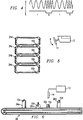
- the timing of the storage capacitor voltage is illustrated in Figure 3.
- Figure 3 illustrates two transmitted signals each of which has a different duration from the power pulse. Varying the duration of the power pulse will advantageously vary the read range and the interrogation speed as discussed below.
- the transmission technique used between the transponder 10 and the reader 12 is frequency shift keying (FSK).
- FSK frequency shift keying
- An FSK signal is illustrated in Figure 4. This approach has comparatively good resistance to noise while also being very cost effective to implement. It should be noted, however, the system of the present invention is not restricted to FM systems or systems operating in sequential power/read modes. It can also be applied to parallel or full duplex systems if power level reduction techniques are being used.
- the identification system described herein overcomes some of the limitations of other systems because it does not require line-of-sight between the transponder and the reader. This means that the system can work effectively in environments with excessive dirt, dust, moisture, and poor visibility. In addition, because it can be designed to work at relatively low frequencies, the system can also work through most nonmetallic materials.
- the method and system of the present invention are most useful when used with applications with multiple non-line-of-sight transponders which are disposed near to one another. Since there is no line-of-sight requirement for a transponder to be read, several transponders which are near to one another may each respond to a single interrogation signal. The interrogation unit must then distinguish between the possible multiple return signals which may interfere.
- each of the transponders 10a-10d is embedded in a respective tyre 24a-24d. As described above, each of the transponders 10a-10d stores an identification code which is to be supplied to the reader 12 in response to an interrogation pulse.
- One method of incorporating a transponder in a tyre is described in TI-17510. See above.
- the reader 12 is preferably a hand held interrogation unit (HHU).
- HHU hand held interrogation unit
- the reader 12 can move while the transponders either move or remain still.
- the tyres 24a-d are stacked or otherwise piled while an individual moves the reader 12 near the pile.
- the reader 12 is stationary and the transponders 10a-d are moved back and forth in the vicinity of the reader 12. It is not critical whether the transponders 10a-d or the reader 12 are moved so long as the distance between them is varied.
- the position of neither the transponder nor the reader is changed, but the reader reads by changing the read range. This embodiment is less preferred because the closest transponder may still dominate all responses.
- Figures 6 and 7 illustrate two of these applications.
- Figure 6 illustrates an application where transponders 10a-d are used to track luggage 26a-d, for example in an airport.
- Each of the transponders 10a-d is disposed near one of the pieces of luggage 26a-d which are illustrated on a conveyor belt 28.
- the luggage 26a-d passes near reader antenna 14 which is coupled to reader 12.
- FIG 7 illustrates an application where each of the transponders 10a-c is associated with a piece of laundry 30a-c.
- the transponders 10a-c can be attached, for example, to shirt collars and pant waistbands under a heat-sealed garment label.
- the garments 30a-30c are illustrated on a rack 32 (which can be a conveyor or a stationary rack).
- the transponders 30a-30c can be read at any one of the laundry process steps by reader 12 through antenna 14.
- the reader starts with a low number of interrogations at medium or large reading range followed by a series of shorter range interrogations.
- An interrogation is the act of transmitting an interrogation signal to effect a response from a transponder 10.
- the read range is a measure of how far apart the transponder 10 and the reader 12 may be and still be able to communicate.
- the read range can be increased by increasing the duration of the power pulse (see Figure 3).
- An example of three input pulses with varying read ranges is illustrated in Figure 9. In this example, the duration of the power pulse is varied between 50 msec, 20 msec and 10 msec. In each case, a time 20 msec is allocated for the data transmit (see Figure 3).
- a high range interrogation signal is transmitted from the interrogation unit 12.
- the interrogation unit 12 receives a first response signal and then transmits a medium range interrogation signal.
- a second response signal is then received at the reader 12.
- these response signals have been generated by one of the transponders 10.
- a long range interrogation signal with a duration of 50 msec may typically provide a read range on the order of 0.5 meters.
- a medium range interrogation signal with a duration of 20 msec may typically provide a read range on the order of 0.3 meters and a short range interrogation signal with a duration of 10 msec may typically provide a read range on the order of 0.15 meters. It should be understood, however, these read ranges are provided strictly as examples and will vary depending upon the system and the application.
- the read range can be increased by increasing the power transmitted by the reader.
- the H-field excitation or power level will be varied between about 68 and 130 dB ⁇ A/m. (referenced to a measurement distance of one meter). Combinations of varying duration and power can also be utilized.
- the reader 12 may transmit one or more of each read range signal before beginning transmission of a different range signal.
- the sequence for transmitting signals comprises transmitting about 2-3 long range signals, followed by about 1-4 medium range signals, and then followed by about 1-6 short range signals. This sequence is preferably repeated about 2-4 times.
- the results from the data received from the long, medium and short range pulses are compared. If unanimous reading results are obtained, the chances are very high the read was successful and the data is displayed in a timely fashion when the reader passes the location or position of the object to be determined. If, however, the results are not unanimous but the high and medium range results are consistent, the number can also be displayed. If a higher degree of accuracy is required, the transponders can be rescanned.
- the medium range result is inconsistent, successively shorter ranges at higher interrogation speed are triggered. If these results are consistent, the results are displayed. If, however, the results are inconsistent, a message can be displayed asking the operator of the reader to scan again to confirm the indicated result.
- the reader 12 or a conveyor belt 28 as in Figure 6 or a pallet car which is not shown
- each transponder 10 will be read many times.
- the system described herein will vary the read range and the operator can vary the distance between the reader 12 and the transponders 10. This act of moving the reader and the algorithm of varying the power will combine to maximize the chance of obtaining a correct reading.
- the present invention can be utilized in applications which do more than simply identify an object.
- One of these other advantageous embodiments is utilized with transponders having Read/Write capability. A certain sequence or other data can be written into the transponder. This data can then be used to identify specific components or objects at a later time or in different regrouped configurations. In other words, the present invention can be used in a half duplex system.
Abstract
Description
- This invention generally relates to identification systems and more specifically to a system and method for reading multiple RF-ID transponders.
- There is a great need for devices or apparatuses which make it possible to identify or detect objects in contactless manner and over a certain distance. In addition, a need exists to be able to change the data stored in, or operating characteristics of, these devices or apparatuses (e.g., "program" the devices or apparatuses).
- It is, for example, desirable to contactlessly request, over a certain distance, identifications which are uniquely assigned to an object. These identifications could be stored in the device or apparatus so that, for example, the object may be identified. A determination may also be made as to whether or not a particular object exists within a given reading range.
- As another example, physical parameters such as temperature or pressure can be interrogated directly even when direct contact to the object is not possible. A device or apparatus of the type desired can, for example, be attached to an animal which can then always be identified at an interrogation point without direct contact.
- There is also a need for a device which, when carried by a person, permits access checking whereby only persons whose responder unit returns certain identification data to the interrogation unit are allowed access to a specific area. In this case the safeguarding of the data transfer is a very essential factor in the production of such devices.
- A further example of a case in which such a device is needed is the computer controlled industrial production in which, without the intervention of operating personnel, components are taken from a store, transported to a production location and there assembled to give a finished product. In this case a device is required which can be attached to the individual components so that the components can be specifically detected in the spares store and taken therefrom.
- Several transponder arrangements have been developed. One such transponder arrangement is described in U.S. Patent No. 5,053,774 issued to Schuermann et al. on October 1, 1991, incorporated herein by reference. This patent describes a transponder unit which has a low energy requirement and does not need its own power source. Another transponder arrangement is disclosed by Meier et al. (TI-16688) European Patent Application No. 93118996.3. In this application, another transponder arrangement which may be updated in a contactless manner subsequent to its manufacture is described.
- A problem arises when multiple non-line-of-sight transponders are disposed near to one another. Since there is no line-of-sight requirement before a transponder to be read, several transponders which are near to one another may each respond to a single interrogation signal. The interrogation unit must then distinguish between the possible multiple return signals which may interfere and associate the identification number with the object's position.
- The solution of this problem, as well as other advantages, are accomplished by the present invention which provides a low cost system and method for reading multiple RF-ID transponders without the need for any particular transponder "anti-collision" protocol.
- A system and method for communicating between an identification reader and a transponder unit is disclosed herein. A first interrogation signal is transmitted from the reader. This first interrogation signal has a first read range. The reader then receives first response signal and transmits a second interrogation signal. The second interrogation signal has a second read range which is different than the first read range. The read range can be varied by varying either the amplitude or duration of the power level of the interrogation signal. A second (or third or fourth etc.) response signal is then received at the reader. These responses are compared to determine a correct response signal which can be displayed. In this manner, a correct response from the strongest transponder can be obtained and incorrect indications which can result from multiple simultaneous responses avoided. It is assumed that the reader distance relative to the transponder moves during the interrogation and the interrogation cycles are short compared to the moving speed of the reader (which may be a hand held reader or in a fixed position where the reader is stationary and the object moves as in baggage on a conveyor belt).
- In addition, the reader can measure and associate the strength of the signal from the transponder to the data received from subsequent signals to determine the transponder(s) to be identified, e.g., with majority voting/validating algorithms.
- The present invention has a number of advantages. Prior art systems often must touch the identification unit to be read. This creates a great inconvenience, especially if the items are arranged in an arbitrary pile or even if they are stacked. Other systems, such as bar codes, require a line-of-sight reading. In the system of the present invention, on the other hand, there is no requirement that the transponder be visible to the interrogation unit. In fact, in some products which are to be tracked, the transponder can be embedded in the actual product. An example of this embodiment relating to tyres is described (TI-17510) European Patent Application No. 94106583.1.
- The present invention also provides for the identification of individual but adjacent transponders. One example relating to the TI-17510 case is stacked tyres. In other words, the present invention can be utilized to read each of the identification codes attached to each tyre in a stack of tyres. Of course, the present invention can also be used with other products such as baggage, laundry as well as in many other identification applications.
- The above features of the present invention will be more clearly understood from consideration of the following descriptions in connection with accompanying drawings in which:
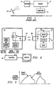
- Figure 1 illustrates a block diagram of an identification system;
- Figure 2 illustrates a schematic diagram of an example of the system of Figure 1;
- Figure 3 illustrates a storage capacitor voltage during an interrogation cycle;
- Figure 4 illustrates a diagram of the signal levels for an frequency shift keyed signal;
- Figure 5 illustrates an exemplary application for the use of the method and system of the present invention;
- Figure 6 illustrates a second exemplary application where the method and system are used to identify baggage;
- Figure 7 illustrates a third exemplary application where the method and system are used to identify laundry;
- Figure 8 illustrates a block diagram of a method of the present invention; and
- Figure 9 illustrates a series of signals with varying read ranges.
- Corresponding numerals and symbols in the different figures refer to corresponding parts unless otherwise indicated.
- The making and use of the presently preferred embodiments are discussed below in detail. However, it should be appreciated that the present invention provides many applicable inventive concepts which can be embodied in a wide variety of specific contexts. The specific embodiments discussed are merely illustrative of specific ways to make and use the invention, and do not limit the scope of the invention.
- The following is a description of a system and method of the present invention. A simplified example of one system will first be described. A preferred embodiment will then be described in the context of an application where each transponder is embedded in a tyre (although many other applications can also utilize the invention).
- The present invention can be utilized with a number of identification systems. A simplified example of just one of these systems will be described with respect to Figure 1. The details of the electronics of one such system are described in U.S. Patent No. 5,053,774 (issued October 1, 1991) and incorporated herein by reference. Another transponder arrangement is disclosed in TI-16688 mentioned above. Although the basic system may be known, the method of using the system is novel, and the known system can be modified to facilitate the present invention as will be described herein.
- Referring now to Figure 1, a
transponder 10 is provided. Thetransponder 10 can be attached to or embedded in an object (not shown). This object can be almost anything imaginable including a tyre, baggage, laundry, a trash container, a vehicle, a security badge, or even a living animal. Information stored in the transponder can be accessed by a reader (or interrogation unit) 12. Areader antenna 14 and optionally to acomputer 16 are coupled to thereader 12. - To interrogate the
transponder 10, thereader 12 sends out a power burst to thetransponder 10 via theantenna 14. In one application, the power burst charges up the passive (e.g., battery free) transponder in about 50 milliseconds. Thetransponder 10 returns a signal that carries the data that is stored within it. In the case of a read only transponder the data is a unique programmed bit code. In read/write applications, the data comprises the contents of a memory included within thetransponder 10. Accordingly, the present invention can be used in a half duplex system. In a typical application, the entire read cycle can be performed in about 70 milliseconds. The data collected from thetransponder 10 can either be sent directly to a computer 16 (e.g., through standard interfaces), or it can be stored in a portable reader and later uploaded to a computer or other system. - The operation of an exemplary system will be described with reference to Figures 2-4. Reference should first be made to Figure 2. When the
transponder 10 is to be read, thereader 12 sends out a power pulse to thereader antenna 14. A portion of the field generated is "collected" by thetransponder antenna 18 coupled totransponder 10. Theantennas capacitor 22 within thetransponder 10. When the power pulse has finished, thetransponder 10 immediately transmits back its data code, using the energy stored within itscapacitor 22 as the power source. - This data is picked up by the
reader antenna 14 and decoded by thereader 12. Once all data has been sent, thestorage capacitor 22 can be discharged thereby resetting thetransponder 10 to make it ready for the next read cycle. The period between transmission pulses can be referred to as the "sync time" and will last as long as the system set up. The timing of the storage capacitor voltage is illustrated in Figure 3. Figure 3 illustrates two transmitted signals each of which has a different duration from the power pulse. Varying the duration of the power pulse will advantageously vary the read range and the interrogation speed as discussed below. - In the preferred embodiment, the transmission technique used between the
transponder 10 and thereader 12 is frequency shift keying (FSK). An FSK signal is illustrated in Figure 4. This approach has comparatively good resistance to noise while also being very cost effective to implement. It should be noted, however, the system of the present invention is not restricted to FM systems or systems operating in sequential power/read modes. It can also be applied to parallel or full duplex systems if power level reduction techniques are being used. - Although the present invention can be utilized with any number of systems, the identification system described herein overcomes some of the limitations of other systems because it does not require line-of-sight between the transponder and the reader. This means that the system can work effectively in environments with excessive dirt, dust, moisture, and poor visibility. In addition, because it can be designed to work at relatively low frequencies, the system can also work through most nonmetallic materials.
- The method and system of the present invention are most useful when used with applications with multiple non-line-of-sight transponders which are disposed near to one another. Since there is no line-of-sight requirement for a transponder to be read, several transponders which are near to one another may each respond to a single interrogation signal. The interrogation unit must then distinguish between the possible multiple return signals which may interfere.
- The preferred embodiment of the present invention will now be described in the context of an application where each transponder is embedded in a tyre. Although described in the context of tyres, the present invention will work equally as well in a large number of applications. This particular application has only been chosen to simplify the illustration of a more general principle.
- Referring now to Figure 5, a
reader 12 and plurality of transponders 10a-10d are illustrated. Each of the transponders 10a-10d is embedded in a respective tyre 24a-24d. As described above, each of the transponders 10a-10d stores an identification code which is to be supplied to thereader 12 in response to an interrogation pulse. One method of incorporating a transponder in a tyre is described in TI-17510. See above. - In this embodiment, the
reader 12 is preferably a hand held interrogation unit (HHU). In other words, thereader 12 can move while the transponders either move or remain still. In the illustrative embodiment, the tyres 24a-d are stacked or otherwise piled while an individual moves thereader 12 near the pile. - In other applications, the
reader 12 is stationary and the transponders 10a-d are moved back and forth in the vicinity of thereader 12. It is not critical whether the transponders 10a-d or thereader 12 are moved so long as the distance between them is varied. - In another embodiment, the position of neither the transponder nor the reader is changed, but the reader reads by changing the read range. This embodiment is less preferred because the closest transponder may still dominate all responses.
- As noted above, the present invention can be utilized with a number of applications besides tyres. Figures 6 and 7 illustrate two of these applications. Figure 6 illustrates an application where transponders 10a-d are used to track luggage 26a-d, for example in an airport. Each of the transponders 10a-d is disposed near one of the pieces of luggage 26a-d which are illustrated on a
conveyor belt 28. The luggage 26a-d passes nearreader antenna 14 which is coupled toreader 12. - Figure 7 illustrates an application where each of the transponders 10a-c is associated with a piece of
laundry 30a-c. The transponders 10a-c can be attached, for example, to shirt collars and pant waistbands under a heat-sealed garment label. Thegarments 30a-30c are illustrated on a rack 32 (which can be a conveyor or a stationary rack). Thetransponders 30a-30c can be read at any one of the laundry process steps byreader 12 throughantenna 14. - Although only three embodiments have been illustrated, it should be understood that the present invention can be utilized with many other applications.
- A novel method of reading each of the transponders will now be described with reference to Figures 8 and 9 as well as Figure 5. The
reader 12 is moved so that it can read each of thetransponders 10 in the stack of tyres 24a-d. When two transponders are both in field (i.e., within range to be read by reader 12), both will return a signal. If one of these signals is slightly stronger, thereader 12 will read the dominating signal and will suppress the slightly weaker signal. A ratio of only a few decibels (dB) between the two signals will suffice. This fact demonstrates one of the advantages an FSK system has over an ASK (amplitude shift keying) system where a 20-30 dB difference is normally required to differentiate signals. - The reader starts with a low number of interrogations at medium or large reading range followed by a series of shorter range interrogations. An interrogation is the act of transmitting an interrogation signal to effect a response from a
transponder 10. The read range is a measure of how far apart thetransponder 10 and thereader 12 may be and still be able to communicate. The read range can be increased by increasing the duration of the power pulse (see Figure 3). An example of three input pulses with varying read ranges is illustrated in Figure 9. In this example, the duration of the power pulse is varied between 50 msec, 20 msec and 10 msec. In each case, atime 20 msec is allocated for the data transmit (see Figure 3). In other words, in this example, a high range interrogation signal is transmitted from theinterrogation unit 12. Theinterrogation unit 12 receives a first response signal and then transmits a medium range interrogation signal. A second response signal is then received at thereader 12. Of course, these response signals have been generated by one of thetransponders 10. - A long range interrogation signal with a duration of 50 msec may typically provide a read range on the order of 0.5 meters. In this same system, a medium range interrogation signal with a duration of 20 msec may typically provide a read range on the order of 0.3 meters and a short range interrogation signal with a duration of 10 msec may typically provide a read range on the order of 0.15 meters. It should be understood, however, these read ranges are provided strictly as examples and will vary depending upon the system and the application.
- Alternatively, the read range can be increased by increasing the power transmitted by the reader. In typical embodiments, the H-field excitation or power level will be varied between about 68 and 130 dBµA/m. (referenced to a measurement distance of one meter). Combinations of varying duration and power can also be utilized.
- The
reader 12 may transmit one or more of each read range signal before beginning transmission of a different range signal. In the preferred embodiment, the sequence for transmitting signals comprises transmitting about 2-3 long range signals, followed by about 1-4 medium range signals, and then followed by about 1-6 short range signals. This sequence is preferably repeated about 2-4 times. - Returning to Figure 8, the results from the data received from the long, medium and short range pulses are compared. If unanimous reading results are obtained, the chances are very high the read was successful and the data is displayed in a timely fashion when the reader passes the location or position of the object to be determined. If, however, the results are not unanimous but the high and medium range results are consistent, the number can also be displayed. If a higher degree of accuracy is required, the transponders can be rescanned.
- If the medium range result is inconsistent, successively shorter ranges at higher interrogation speed are triggered. If these results are consistent, the results are displayed. If, however, the results are inconsistent, a message can be displayed asking the operator of the reader to scan again to confirm the indicated result. In an automatic moving identification environment, the reader 12 (or a
conveyor belt 28 as in Figure 6 or a pallet car which is not shown) can be moved back and forth. - As the
reader 12 is moved near the pile of tyres 24a-d, eachtransponder 10 will be read many times. The system described herein will vary the read range and the operator can vary the distance between thereader 12 and thetransponders 10. This act of moving the reader and the algorithm of varying the power will combine to maximize the chance of obtaining a correct reading. - The present invention can be utilized in applications which do more than simply identify an object. One of these other advantageous embodiments is utilized with transponders having Read/Write capability. A certain sequence or other data can be written into the transponder. This data can then be used to identify specific components or objects at a later time or in different regrouped configurations. In other words, the present invention can be used in a half duplex system.
- While this invention has been described with reference to illustrative embodiments, this description is not intended to be construed in a limiting sense. Various modifications and combinations of the illustrative embodiments, as well as other embodiments of the invention, will be apparent to persons skilled in the art upon reference to the description. It is therefore intended that the appended claims encompass any such modifications or embodiments.
Claims (18)
- A method of communicating between an identification reader and a transponder unit, said method comprising the steps of:
transmitting a first interrogation signal from said reader, said first interrogation signal having a first read range;
receiving a first response signal at said reader;
transmitting a second interrogation signal from said reader, said second interrogation signal having a second read range which is different than said first read range;
receiving a second response signal at said reader; and
comparing said first response signal to said second response signal to determine a correct response signal. - The method of claim 1, further comprising the step of varying the distance between the reader and the transponder unit.
- The method of claim 1 or claim 2, further comprising the step of displaying an output based upon said correct response if said first and second response signals match.
- The method of any preceding claim, further comprising repeating said steps of transmitting a first interrogation signal, receiving a first response signal, transmitting a second interrogation signal, receiving a second response signal, and comparing said first and second response signals if said first and second response signals do not match.
- The method of any preceding claim, further comprising the steps of:
transmitting a third interrogation signal from said reader, said third interrogation signal having a third read range;
receiving a third response signal at said reader; and
comparing said third response signal to said first and second response signals to determine a correct response signal. - The method of claim 5, wherein:
said step of transmitting a first interrogation signal comprises transmitting said first interrogation signal two to three times;
said step of transmitting a second interrogation signal comprises transmitting said second interrogation signal one to four times; and
said step of transmitting a first interrogation signal comprises transmitting said first interrogation signal one to six times. - The method of any preceding claims, wherein said first interrogation signal has a first duration and said second interrogation signal has a second duration different than said first duration.
- The method of claim 7, further comprising producing said first duration to be longer than said second duration.
- The method of claim 7 or claim 8, further comprising providing said first interrogation signal having a duration of about 50 msec.
- The method of claim 7 or 8, further comprising providing said first interrogation signal having a duration of about 20 msec.
- The method of claim 7 or claim 8, further comprising providing said first interrogation signal having a duration of about 10 msec.
- The method of any preceding claims, wherein said first interrogation signal has a first power level and said second interrogation signal has a second power level different than said first duration.
- The method of any preceding claims, further comprising providing said first read range higher than said second read range and transmitting said first interrogation signal before the second interrogation signal.
- The method of any preceding claim, wherein said step of transmitting a first interrogation signal comprises transmitting more than one interrogation signal.
- The method of any preceding claim, further comprising providing said reader as a hand held interrogation unit.
- The method of any preceding claim, further comprising providing said first and second interrogation signals as FSK signals.
- A method for identifying each object within a plurality of objects, said method comprising:
providing a plurality of transponders
associating one of said transponders with each object such that each of said transponders is disposed near one of said objects;
directing a first interrogation signal toward at least two of said plurality of objects, said first interrogation signal having a first read range;
transmitting a first response signal from at least one of said transponders in response to said first interrogation signal;
receiving said first response signal at a reader;
transmitting a second interrogation signal from said reader, said second interrogation signal having a second read range which is different than said first read range;
directing a second interrogation signal toward at least two of said plurality of objects, said second interrogation signal having a second read range;
transmitting a second response signal from at least one transponders in response to said second interrogation signal;
receiving said second response signal at said reader; and
comparing said first response signal to said second response signal to determine a correct response signal. - An interogation unit comprising a transponder unit and an identification reader wherein a first interrogation signal is transmitted from said reader, the first interrogation signal having a first read range;
a second interrogation signal is transmitted from said reader, said second interrogation signal having a second read range which is different than said first read range;
the first and seond response signal are received at said reader; and
wherein said first response signal is compared to said second response signal to determne a correct response signal.
Applications Claiming Priority (2)
| Application Number | Priority Date | Filing Date | Title |
|---|---|---|---|
| US265545 | 1994-06-24 | ||
| US08/265,545 US5500651A (en) | 1994-06-24 | 1994-06-24 | System and method for reading multiple RF-ID transponders |
Publications (2)
| Publication Number | Publication Date |
|---|---|
| EP0689161A2 true EP0689161A2 (en) | 1995-12-27 |
| EP0689161A3 EP0689161A3 (en) | 1998-12-23 |
Family
ID=23010904
Family Applications (1)
| Application Number | Title | Priority Date | Filing Date |
|---|---|---|---|
| EP95304408A Withdrawn EP0689161A3 (en) | 1994-06-24 | 1995-06-23 | Identification system |
Country Status (3)
| Country | Link |
|---|---|
| US (1) | US5500651A (en) |
| EP (1) | EP0689161A3 (en) |
| JP (1) | JP3745794B2 (en) |
Cited By (13)
| Publication number | Priority date | Publication date | Assignee | Title |
|---|---|---|---|---|
| EP0944015A2 (en) * | 1998-03-17 | 1999-09-22 | Supersensor (Proprietary) Limited | Interrogator with variable maximum output power |
| FR2780585A1 (en) * | 1998-06-30 | 1999-12-31 | Alessandro Manneschi | APPARATUS AND METHOD FOR DETECTION AND READING OF IDENTIFICATION RESPONDERS IN A CONTROLLED PASS |
| FR2790622A1 (en) * | 1999-03-05 | 2000-09-08 | Berner Fachhochschule Hochschu | TRANSPONDER AND ARCHIVE MANAGER USING SUCH TRANSPONDERS |
| WO2001037202A1 (en) * | 1999-11-08 | 2001-05-25 | Tagmaster Ab | Interference protection |
| WO2002048955A1 (en) * | 2000-12-12 | 2002-06-20 | 3M Innovative Properties Company | Object tracking and management system and method using radio-frequency identification tags |
| EP0722094B1 (en) * | 1995-01-11 | 2002-11-27 | Sony Chemicals Corporation | Transmitter-receiver for non-contact IC card system |
| FR2834398A1 (en) * | 2001-12-27 | 2003-07-04 | Siemens Vdo Automotive | METHOD FOR ISSUING A REQUEST TO A BADGE |
| US6671599B2 (en) | 2001-02-02 | 2003-12-30 | Siemens Vdo Automotive | Process for monitoring the state of a safety facility |
| US6669089B2 (en) | 2001-11-12 | 2003-12-30 | 3M Innovative Properties Co | Radio frequency identification systems for asset tracking |
| US6768419B2 (en) | 1998-08-14 | 2004-07-27 | 3M Innovative Properties Company | Applications for radio frequency identification systems |
| WO2007018840A2 (en) | 2005-07-20 | 2007-02-15 | Intelleflex Corporation | Ramped interrogation power levels |
| US7447251B2 (en) | 2003-03-31 | 2008-11-04 | Intermec Ip Corp. | Frequency hopping spread spectrum scheme for RFID reader |
| US8006902B2 (en) | 1998-08-14 | 2011-08-30 | 3M Innovative Properties Company | Radio frequency identification systems applications |
Families Citing this family (142)
| Publication number | Priority date | Publication date | Assignee | Title |
|---|---|---|---|---|
| US6097301A (en) | 1996-04-04 | 2000-08-01 | Micron Communications, Inc. | RF identification system with restricted range |
| US20050040961A1 (en) * | 1995-04-11 | 2005-02-24 | Tuttle John R. | RF identification system with restricted range |
| US6249212B1 (en) * | 1994-10-05 | 2001-06-19 | Avid Marketing, Inc. | Universal electronic identification tag |
| JPH08307308A (en) * | 1995-01-12 | 1996-11-22 | Texas Instr Deutschland Gmbh | Charging capacitor discharge controller in transponder |
| US7079044B1 (en) * | 1995-01-27 | 2006-07-18 | Steelcase Development Corporation | Electronic system, components and method for tracking files |
| US5793324A (en) * | 1996-01-19 | 1998-08-11 | Texas Instruments Incorporated | Transponder signal collision avoidance system |
| US5864301A (en) * | 1996-05-13 | 1999-01-26 | Jackson; Jerome D. | Systems and methods employing a plurality of signal amplitudes to identify an object |
| JPH09318478A (en) * | 1996-05-27 | 1997-12-12 | Yokohama Rubber Co Ltd:The | Internal pressure detector of pneumatic fender material |
| KR100489716B1 (en) * | 1996-11-05 | 2005-09-12 | 코닌클리케 필립스 일렉트로닉스 엔.브이. | Contactless data transmitter and receiver with synchronous demodulator |
| US6118367A (en) | 1996-11-29 | 2000-09-12 | Yoshikawa Rf Systems Co., Ltd. | Data carrier system |
| FR2781587B1 (en) * | 1998-07-21 | 2000-09-08 | Dassault Electronique | ADVANCED READER FOR NON-CONTACT BADGES |
| US6087940A (en) * | 1998-07-28 | 2000-07-11 | Novavision, Inc. | Article surveillance device and method for forming |
| AU5917899A (en) * | 1998-09-11 | 2000-04-03 | Motorola, Inc. | A contactless capacitive data transmission system and method |
| US8538801B2 (en) | 1999-02-19 | 2013-09-17 | Exxonmobile Research & Engineering Company | System and method for processing financial transactions |
| JP2003500975A (en) | 1999-05-21 | 2003-01-07 | ケーナー,ラルフ・ジェイ | Identification system for monitoring the presence / absence of members of a defined set |
| US6784789B2 (en) * | 1999-07-08 | 2004-08-31 | Intermec Ip Corp. | Method and apparatus for verifying RFID tags |
| US6714121B1 (en) | 1999-08-09 | 2004-03-30 | Micron Technology, Inc. | RFID material tracking method and apparatus |
| US7239226B2 (en) | 2001-07-10 | 2007-07-03 | American Express Travel Related Services Company, Inc. | System and method for payment using radio frequency identification in contact and contactless transactions |
| US7070112B2 (en) | 1999-09-07 | 2006-07-04 | American Express Travel Related Services Company, Inc. | Transparent transaction device |
| US7837116B2 (en) | 1999-09-07 | 2010-11-23 | American Express Travel Related Services Company, Inc. | Transaction card |
| US7889052B2 (en) | 2001-07-10 | 2011-02-15 | Xatra Fund Mx, Llc | Authorizing payment subsequent to RF transactions |
| US7093767B2 (en) * | 1999-09-07 | 2006-08-22 | American Express Travel Related Services Company, Inc. | System and method for manufacturing a punch-out RFID transaction device |
| US6963270B1 (en) * | 1999-10-27 | 2005-11-08 | Checkpoint Systems, Inc. | Anticollision protocol with fast read request and additional schemes for reading multiple transponders in an RFID system |
| US7172112B2 (en) | 2000-01-21 | 2007-02-06 | American Express Travel Related Services Company, Inc. | Public/private dual card system and method |
| US8543423B2 (en) | 2002-07-16 | 2013-09-24 | American Express Travel Related Services Company, Inc. | Method and apparatus for enrolling with multiple transaction environments |
| US8429041B2 (en) | 2003-05-09 | 2013-04-23 | American Express Travel Related Services Company, Inc. | Systems and methods for managing account information lifecycles |
| US7268668B2 (en) * | 2003-05-09 | 2007-09-11 | American Express Travel Related Services Company, Inc. | Systems and methods for managing multiple accounts on a RF transaction instrument |
| US6377203B1 (en) | 2000-02-01 | 2002-04-23 | 3M Innovative Properties Company | Collision arbitration method and apparatus for reading multiple radio frequency identification tags |
| AU2001243473A1 (en) | 2000-03-07 | 2001-09-17 | American Express Travel Related Services Company, Inc. | System for facilitating a transaction |
| FR2817684B1 (en) * | 2000-12-05 | 2006-03-17 | Gemplus Card Int | ANTENNA DEVICE FOR READING ELECTRONIC LABELS AND SYSTEM INCLUDING SUCH A DEVICE |
| US20040069851A1 (en) * | 2001-03-13 | 2004-04-15 | Grunes Mitchell B. | Radio frequency identification reader with removable media |
| US7725427B2 (en) * | 2001-05-25 | 2010-05-25 | Fred Bishop | Recurrent billing maintenance with radio frequency payment devices |
| US7650314B1 (en) | 2001-05-25 | 2010-01-19 | American Express Travel Related Services Company, Inc. | System and method for securing a recurrent billing transaction |
| US7542942B2 (en) | 2001-07-10 | 2009-06-02 | American Express Travel Related Services Company, Inc. | System and method for securing sensitive information during completion of a transaction |
| US20050032151A1 (en) * | 2001-06-05 | 2005-02-10 | Eisenberg Peter M. | Methods of managing the transfer and use of data |
| US7588185B2 (en) * | 2001-06-07 | 2009-09-15 | 3M Innovative Properties Company | RFID data collection and use |
| US20040232222A1 (en) * | 2001-07-10 | 2004-11-25 | American Express Travel Related Services Company, Inc. | Method and system for signature recognition biometrics on a fob |
| US20040233037A1 (en) * | 2001-07-10 | 2004-11-25 | American Express Travel Related Services Company, Inc. | Method and system for iris scan recognition biometrics on a fob |
| US20050160003A1 (en) * | 2001-07-10 | 2005-07-21 | American Express Travel Related Services Company, Inc. | System and method for incenting rfid transaction device usage at a merchant location |
| US7493288B2 (en) * | 2001-07-10 | 2009-02-17 | Xatra Fund Mx, Llc | RF payment via a mobile device |
| US8548927B2 (en) | 2001-07-10 | 2013-10-01 | Xatra Fund Mx, Llc | Biometric registration for facilitating an RF transaction |
| US20040233039A1 (en) * | 2001-07-10 | 2004-11-25 | American Express Travel Related Services Company, Inc. | System for registering a biometric for use with a transponder |
| US20040232221A1 (en) * | 2001-07-10 | 2004-11-25 | American Express Travel Related Services Company, Inc. | Method and system for voice recognition biometrics on a fob |
| US8294552B2 (en) | 2001-07-10 | 2012-10-23 | Xatra Fund Mx, Llc | Facial scan biometrics on a payment device |
| US7827106B2 (en) * | 2001-07-10 | 2010-11-02 | American Express Travel Related Services Company, Inc. | System and method for manufacturing a punch-out RFID transaction device |
| US20040239480A1 (en) * | 2001-07-10 | 2004-12-02 | American Express Travel Related Services Company, Inc. | Method for biometric security using a transponder |
| US20050033687A1 (en) * | 2001-07-10 | 2005-02-10 | American Express Travel Related Services Company, Inc. | Method and system for auditory emissions recognition biometrics on a fob |
| US20040239481A1 (en) * | 2001-07-10 | 2004-12-02 | American Express Travel Related Services Company, Inc. | Method and system for facial recognition biometrics on a fob |
| US20050116810A1 (en) * | 2001-07-10 | 2005-06-02 | American Express Travel Related Services Company, Inc. | Method and system for vascular pattern recognition biometrics on a fob |
| US7228155B2 (en) * | 2001-07-10 | 2007-06-05 | American Express Travel Related Services Company, Inc. | System and method for remotely initializing a RF transaction |
| US8960535B2 (en) | 2001-07-10 | 2015-02-24 | Iii Holdings 1, Llc | Method and system for resource management and evaluation |
| US7668750B2 (en) | 2001-07-10 | 2010-02-23 | David S Bonalle | Securing RF transactions using a transactions counter |
| US7805378B2 (en) * | 2001-07-10 | 2010-09-28 | American Express Travel Related Servicex Company, Inc. | System and method for encoding information in magnetic stripe format for use in radio frequency identification transactions |
| US7463133B2 (en) * | 2001-07-10 | 2008-12-09 | American Express Travel Related Services Company, Inc. | Systems and methods for providing a RF transaction device operable to store multiple distinct calling card accounts |
| US7154375B2 (en) * | 2001-07-10 | 2006-12-26 | American Express Travel Related Services Company, Inc. | Biometric safeguard method with a fob |
| US9031880B2 (en) | 2001-07-10 | 2015-05-12 | Iii Holdings 1, Llc | Systems and methods for non-traditional payment using biometric data |
| US7249112B2 (en) * | 2002-07-09 | 2007-07-24 | American Express Travel Related Services Company, Inc. | System and method for assigning a funding source for a radio frequency identification device |
| US7925535B2 (en) * | 2001-07-10 | 2011-04-12 | American Express Travel Related Services Company, Inc. | System and method for securing RF transactions using a radio frequency identification device including a random number generator |
| US7762457B2 (en) * | 2001-07-10 | 2010-07-27 | American Express Travel Related Services Company, Inc. | System and method for dynamic fob synchronization and personalization |
| US7312707B1 (en) | 2001-07-10 | 2007-12-25 | American Express Travel Related Services Company, Inc. | System and method for authenticating a RF transaction using a transaction account routing number |
| US8284025B2 (en) * | 2001-07-10 | 2012-10-09 | Xatra Fund Mx, Llc | Method and system for auditory recognition biometrics on a FOB |
| US7059531B2 (en) * | 2001-07-10 | 2006-06-13 | American Express Travel Related Services Company, Inc. | Method and system for smellprint recognition biometrics on a fob |
| US7996324B2 (en) | 2001-07-10 | 2011-08-09 | American Express Travel Related Services Company, Inc. | Systems and methods for managing multiple accounts on a RF transaction device using secondary identification indicia |
| US20040238621A1 (en) * | 2001-07-10 | 2004-12-02 | American Express Travel Related Services Company, Inc. | Method and system for fingerprint biometrics on a fob |
| US7503480B2 (en) | 2001-07-10 | 2009-03-17 | American Express Travel Related Services Company, Inc. | Method and system for tracking user performance |
| US7746215B1 (en) | 2001-07-10 | 2010-06-29 | Fred Bishop | RF transactions using a wireless reader grid |
| US20040233038A1 (en) * | 2001-07-10 | 2004-11-25 | American Express Travel Related Services Company, Inc. | Method and system for retinal scan recognition biometrics on a fob |
| US8538863B1 (en) | 2001-07-10 | 2013-09-17 | American Express Travel Related Services Company, Inc. | System and method for facilitating a transaction using a revolving use account associated with a primary account |
| US20040236699A1 (en) | 2001-07-10 | 2004-11-25 | American Express Travel Related Services Company, Inc. | Method and system for hand geometry recognition biometrics on a fob |
| US7121471B2 (en) * | 2001-07-10 | 2006-10-17 | American Express Travel Related Services Company, Inc. | Method and system for DNA recognition biometrics on a fob |
| US8001054B1 (en) | 2001-07-10 | 2011-08-16 | American Express Travel Related Services Company, Inc. | System and method for generating an unpredictable number using a seeded algorithm |
| US9454752B2 (en) | 2001-07-10 | 2016-09-27 | Chartoleaux Kg Limited Liability Company | Reload protocol at a transaction processing entity |
| US8635131B1 (en) | 2001-07-10 | 2014-01-21 | American Express Travel Related Services Company, Inc. | System and method for managing a transaction protocol |
| US7360689B2 (en) | 2001-07-10 | 2008-04-22 | American Express Travel Related Services Company, Inc. | Method and system for proffering multiple biometrics for use with a FOB |
| US7429927B2 (en) | 2001-07-10 | 2008-09-30 | American Express Travel Related Services Company, Inc. | System and method for providing and RFID transaction device |
| US20040236700A1 (en) * | 2001-07-10 | 2004-11-25 | American Express Travel Related Services Company, Inc. | Method and system for keystroke scan recognition biometrics on a fob |
| US7119659B2 (en) | 2001-07-10 | 2006-10-10 | American Express Travel Related Services Company, Inc. | Systems and methods for providing a RF transaction device for use in a private label transaction |
| US20040257197A1 (en) * | 2001-07-10 | 2004-12-23 | American Express Travel Related Services Company, Inc. | Method for biometric security using a transponder-reader |
| US9024719B1 (en) | 2001-07-10 | 2015-05-05 | Xatra Fund Mx, Llc | RF transaction system and method for storing user personal data |
| US7303120B2 (en) | 2001-07-10 | 2007-12-04 | American Express Travel Related Services Company, Inc. | System for biometric security using a FOB |
| US7705732B2 (en) | 2001-07-10 | 2010-04-27 | Fred Bishop | Authenticating an RF transaction using a transaction counter |
| AU2002326417A1 (en) * | 2001-07-20 | 2003-03-03 | Hill-Rom Services, Inc. | Badge for a locating and tracking system |
| US7706765B2 (en) * | 2001-10-17 | 2010-04-27 | Motorola, Inc. | Method and device for enabling and disabling group transmissions |
| US7587756B2 (en) * | 2002-07-09 | 2009-09-08 | American Express Travel Related Services Company, Inc. | Methods and apparatus for a secure proximity integrated circuit card transactions |
| US6805287B2 (en) | 2002-09-12 | 2004-10-19 | American Express Travel Related Services Company, Inc. | System and method for converting a stored value card to a credit card |
| US7495544B2 (en) * | 2003-02-03 | 2009-02-24 | Ingrid, Inc. | Component diversity in a RFID security network |
| US7042353B2 (en) | 2003-02-03 | 2006-05-09 | Ingrid, Inc. | Cordless telephone system |
| US7283048B2 (en) | 2003-02-03 | 2007-10-16 | Ingrid, Inc. | Multi-level meshed security network |
| US7079020B2 (en) * | 2003-02-03 | 2006-07-18 | Ingrid, Inc. | Multi-controller security network |
| US7119658B2 (en) | 2003-02-03 | 2006-10-10 | Ingrid, Inc. | Device enrollment in a security system |
| US7079034B2 (en) * | 2003-02-03 | 2006-07-18 | Ingrid, Inc. | RFID transponder for a security system |
| US7057512B2 (en) * | 2003-02-03 | 2006-06-06 | Ingrid, Inc. | RFID reader for a security system |
| US7532114B2 (en) * | 2003-02-03 | 2009-05-12 | Ingrid, Inc. | Fixed part-portable part communications network for a security network |
| US7511614B2 (en) * | 2003-02-03 | 2009-03-31 | Ingrid, Inc. | Portable telephone in a security network |
| US20060132302A1 (en) * | 2003-02-03 | 2006-06-22 | Stilp Louis A | Power management of transponders and sensors in an RFID security network |
| US7091827B2 (en) * | 2003-02-03 | 2006-08-15 | Ingrid, Inc. | Communications control in a security system |
| US8542717B2 (en) * | 2003-03-03 | 2013-09-24 | Veroscan, Inc. | Interrogator and interrogation system employing the same |
| US7268667B2 (en) * | 2003-05-09 | 2007-09-11 | American Express Travel Related Services Company, Inc. | Systems and methods for providing a RF transaction device operable to store multiple distinct accounts |
| US20050003839A1 (en) * | 2003-05-13 | 2005-01-06 | Tripp Jeffrey William | Decision influence data system |
| US20040230487A1 (en) * | 2003-05-13 | 2004-11-18 | Tripp Jeffrey William | Local data access system |
| DE10331316A1 (en) * | 2003-07-10 | 2005-02-10 | Siemens Ag | ferrite |
| JP4304035B2 (en) * | 2003-09-29 | 2009-07-29 | 株式会社ジクシス | Counterfeit product prevention system |
| CA2490015C (en) * | 2003-12-10 | 2015-10-13 | Barry Allen | Method and apparatus for resolving rfid-based object traffic transactions to a single container in the presence of a plurality of containers |
| US7298264B1 (en) * | 2004-01-20 | 2007-11-20 | Charles A. Eldering | RFID tag filtering and monitoring |
| US7420458B1 (en) | 2004-01-20 | 2008-09-02 | Charles A. Eldering | Secondary card reader |
| JPWO2005081420A1 (en) * | 2004-02-19 | 2008-06-19 | 株式会社アンプレット | CDMA-RFID |
| US8407097B2 (en) * | 2004-04-15 | 2013-03-26 | Hand Held Products, Inc. | Proximity transaction apparatus and methods of use thereof |
| US7318550B2 (en) | 2004-07-01 | 2008-01-15 | American Express Travel Related Services Company, Inc. | Biometric safeguard method for use with a smartcard |
| CA2582382A1 (en) * | 2004-10-07 | 2006-04-20 | West Pharmaceutical Services, Inc. | Closure for a container |
| JP2008521101A (en) * | 2004-11-18 | 2008-06-19 | レーン、ロバート | Vehicle transfer method |
| US8049594B1 (en) | 2004-11-30 | 2011-11-01 | Xatra Fund Mx, Llc | Enhanced RFID instrument security |
| US7327257B2 (en) * | 2004-12-17 | 2008-02-05 | Intel Corporation | RFID tag with modifiable and reversible read range |
| JP4208855B2 (en) * | 2005-04-08 | 2009-01-14 | キヤノン株式会社 | Sheet conveying apparatus and image forming apparatus |
| JP4843249B2 (en) * | 2005-05-10 | 2011-12-21 | 富士通株式会社 | Tag information management device and IC tag |
| GB0515523D0 (en) * | 2005-07-28 | 2005-12-07 | Bae Systems Plc | Transponder |
| JPWO2007034543A1 (en) * | 2005-09-21 | 2009-03-19 | パナソニック株式会社 | Tag reader |
| JP4676324B2 (en) * | 2005-11-29 | 2011-04-27 | 株式会社日本コンラックス | Terminal device for communicating with non-contact IC media and communication method therefor |
| FI119453B (en) * | 2006-01-30 | 2008-11-14 | Voyantic Oy | Apparatus and method for radio frequency systems |
| US9087226B2 (en) * | 2006-06-09 | 2015-07-21 | Intelleflex Corporation | System, method and computer program product for calibrating interrogator signal strength and/or tag response range setting |
| AU2007286652B2 (en) * | 2006-08-23 | 2011-05-26 | Hunter Douglas Inc. | Dual control system and method |
| US20090322582A1 (en) * | 2006-09-05 | 2009-12-31 | Hunter Douglas Inc. | System and method for dual media control of remote devices |
| US8519823B2 (en) * | 2006-10-31 | 2013-08-27 | Symbol Technologies, Inc. | Radio frequency identification (RFID) tag location systems and methods |
| US7791453B2 (en) * | 2006-11-21 | 2010-09-07 | International Business Machines Corporation | System and method for varying response amplitude of radio transponders |
| US20080212303A1 (en) * | 2007-03-02 | 2008-09-04 | Warren Farnworth | Device for reducing or preventing exchange of information |
| US20090001941A1 (en) * | 2007-06-29 | 2009-01-01 | Microsoft Corporation | Inductive Powering Surface for Powering Portable Devices |
| KR101396430B1 (en) * | 2007-10-31 | 2014-05-20 | 삼성전자주식회사 | Apparatus and method for anti-collision tag in radio frequency identification system |
| US8355962B2 (en) * | 2008-08-21 | 2013-01-15 | Pickpoint Corporation | Product storage and retrieval system |
| US9619777B2 (en) | 2008-08-21 | 2017-04-11 | Maxor National Pharmacy Services Corp. | Modular hangers for product storage and retrieval system |
| US9043234B2 (en) | 2008-08-21 | 2015-05-26 | Maxor National Pharmacy Services Corp. | Modular hangers for product storage and retrieval system |
| TWI407376B (en) * | 2009-02-13 | 2013-09-01 | Ind Tech Res Inst | Method and system for testing rfid tags |
| US8717145B2 (en) * | 2009-08-25 | 2014-05-06 | Tyco Fire & Security Services GmbH | RFID portal system with RFID tags having various read ranges |
| WO2011093937A2 (en) * | 2009-11-13 | 2011-08-04 | Solstice Medical, Inc. | Method of operating an rfid reader in an rfid system |
| JP5548496B2 (en) * | 2010-03-25 | 2014-07-16 | シスメックス株式会社 | Sample analyzer |
| EP2367013B1 (en) * | 2010-03-18 | 2022-06-22 | Sysmex Corporation | Sample analyzer |
| EP2367014B1 (en) * | 2010-03-18 | 2020-10-14 | Sysmex Corporation | Sample analyzer and reagent information obtaining method |
| GB2478167B (en) * | 2010-06-18 | 2012-02-01 | Friendly Technologies Ltd | Selectively addressing transponders |
| WO2012166090A1 (en) * | 2011-05-27 | 2012-12-06 | Michelin Recherche Et Technique, S.A. | Rfid passive reflector for hidden tags |
| EP2642423B1 (en) * | 2012-03-22 | 2015-06-10 | Nxp B.V. | Combined multifunctional RFID communication device |
| US8963688B2 (en) * | 2012-08-20 | 2015-02-24 | The Goodyear Tire & Rubber Company | Stacked tire RFID reader system and method |
| US9578469B2 (en) | 2014-10-02 | 2017-02-21 | Motorola Solutions, Inc. | Method and system for direct mode communication within a talkgroup |
| WO2019086178A1 (en) | 2017-11-03 | 2019-05-09 | Telefonaktiebolaget Lm Ericsson (Publ) | Receiver, communication apparatus, method and computer program for receiving binary information |
| US10734110B2 (en) | 2018-12-05 | 2020-08-04 | Hill-Rom Services, Inc. | Caregiver locating tag having advanced functionality |
Citations (1)
| Publication number | Priority date | Publication date | Assignee | Title |
|---|---|---|---|---|
| US5053774A (en) | 1987-07-31 | 1991-10-01 | Texas Instruments Deutschland Gmbh | Transponder arrangement |
Family Cites Families (13)
| Publication number | Priority date | Publication date | Assignee | Title |
|---|---|---|---|---|
| US3969616A (en) * | 1965-06-29 | 1976-07-13 | General Dynamics Corporation | Digital range computer systems for air navigation systems such as tacan |
| US3870994A (en) * | 1972-12-22 | 1975-03-11 | Bendix Corp | Geographic addressing by interrogation for controlling airport ground traffic |
| US3882497A (en) * | 1973-07-02 | 1975-05-06 | Honeywell Inc | Synchronizing techniques for an aircraft collision avoidance system |
| US3936823A (en) * | 1974-08-01 | 1976-02-03 | Rockwell International Corporation | Fast search and lock-on means for distance measuring equipment |
| GB1572903A (en) * | 1976-06-30 | 1980-08-06 | Mcgeoch I | Method and appratus for identifying radar targets |
| US4124850A (en) * | 1977-06-07 | 1978-11-07 | The Bendix Corporation | Video processor for distance measuring equipment |
| US4229737A (en) * | 1978-02-06 | 1980-10-21 | Cubic Western Data | Ranging system and method for determining the range of a vehicle from a plurality of reference points |
| US4633251A (en) * | 1982-09-18 | 1986-12-30 | Mcgeoch Ian L M | Method and apparatus for identifying radar targets |
| ATE110480T1 (en) * | 1987-03-31 | 1994-09-15 | Identec Ltd | ACCESS CONTROL DEVICE. |
| JP2533800B2 (en) * | 1989-06-02 | 1996-09-11 | 山武ハネウエル株式会社 | Microwave response device |
| KR100251666B1 (en) * | 1992-04-29 | 2000-04-15 | 윌리엄 비. 켐플러 | Method of remotely sensing an environmental condition |
| US5294931A (en) * | 1992-04-29 | 1994-03-15 | Texas Instruments Deutschland Gmbh | Method of interrogating a plurality of transponders arranged in the transmission range of an interrogating device and transponders for use in the said method |
| US5367303A (en) * | 1993-09-17 | 1994-11-22 | Alliedsignal Inc. | Parallel observer spatial evaluator |
-
1994
- 1994-06-24 US US08/265,545 patent/US5500651A/en not_active Expired - Lifetime
-
1995
- 1995-06-23 EP EP95304408A patent/EP0689161A3/en not_active Withdrawn
- 1995-06-26 JP JP15957395A patent/JP3745794B2/en not_active Expired - Lifetime
Patent Citations (1)
| Publication number | Priority date | Publication date | Assignee | Title |
|---|---|---|---|---|
| US5053774A (en) | 1987-07-31 | 1991-10-01 | Texas Instruments Deutschland Gmbh | Transponder arrangement |
Cited By (27)
| Publication number | Priority date | Publication date | Assignee | Title |
|---|---|---|---|---|
| EP0722094B1 (en) * | 1995-01-11 | 2002-11-27 | Sony Chemicals Corporation | Transmitter-receiver for non-contact IC card system |
| EP0944015A2 (en) * | 1998-03-17 | 1999-09-22 | Supersensor (Proprietary) Limited | Interrogator with variable maximum output power |
| EP0944015A3 (en) * | 1998-03-17 | 2000-03-01 | Supersensor (Proprietary) Limited | Interrogator with variable maximum output power |
| FR2780585A1 (en) * | 1998-06-30 | 1999-12-31 | Alessandro Manneschi | APPARATUS AND METHOD FOR DETECTION AND READING OF IDENTIFICATION RESPONDERS IN A CONTROLLED PASS |
| GB2339115A (en) * | 1998-06-30 | 2000-01-12 | Alessandro Manneschi | Apparatus for detecting and reading transponders in a controlled passageway |
| ES2150873A1 (en) * | 1998-06-30 | 2000-12-01 | Alessandro Manneschi | Apparatus and operative method for detection and reading of transponders in a controlled passage |
| GB2339115B (en) * | 1998-06-30 | 2003-06-25 | Alessandro Manneschi | Apparatus and operative method for detection and reading of transponders in a controlled passage |
| EP2259239A3 (en) * | 1998-08-14 | 2011-01-26 | 3M Innovative Properties Company | Applications for radio frequency identification systems |
| US7728732B2 (en) | 1998-08-14 | 2010-06-01 | 3M Innovative Properties Company | Applications for radio frequency identification systems |
| US8006902B2 (en) | 1998-08-14 | 2011-08-30 | 3M Innovative Properties Company | Radio frequency identification systems applications |
| US6768419B2 (en) | 1998-08-14 | 2004-07-27 | 3M Innovative Properties Company | Applications for radio frequency identification systems |
| US8502673B2 (en) | 1998-08-14 | 2013-08-06 | 3M Innovative Properties Company | Applications for radio frequency identification systems |
| WO2000054209A1 (en) | 1999-03-05 | 2000-09-14 | Berner Fachhochschule Hochschule Fur Technik Und Arcitektur Biel | Transponder and archive manager using same |
| FR2790622A1 (en) * | 1999-03-05 | 2000-09-08 | Berner Fachhochschule Hochschu | TRANSPONDER AND ARCHIVE MANAGER USING SUCH TRANSPONDERS |
| WO2001037202A1 (en) * | 1999-11-08 | 2001-05-25 | Tagmaster Ab | Interference protection |
| US7239657B1 (en) | 1999-11-08 | 2007-07-03 | Tagmaster Ag | Interference protection |
| US6600418B2 (en) | 2000-12-12 | 2003-07-29 | 3M Innovative Properties Company | Object tracking and management system and method using radio-frequency identification tags |
| WO2002048955A1 (en) * | 2000-12-12 | 2002-06-20 | 3M Innovative Properties Company | Object tracking and management system and method using radio-frequency identification tags |
| AU2001259116B2 (en) * | 2000-12-12 | 2007-12-13 | 3M Innovative Properties Company | Object tracking and management system and method using radio-frequency identification tags |
| US6671599B2 (en) | 2001-02-02 | 2003-12-30 | Siemens Vdo Automotive | Process for monitoring the state of a safety facility |
| US6669089B2 (en) | 2001-11-12 | 2003-12-30 | 3M Innovative Properties Co | Radio frequency identification systems for asset tracking |
| EP1326195A1 (en) * | 2001-12-27 | 2003-07-09 | Siemens VDO Automotive S.A.S. | Method for transmitting a query to a tag |
| FR2834398A1 (en) * | 2001-12-27 | 2003-07-04 | Siemens Vdo Automotive | METHOD FOR ISSUING A REQUEST TO A BADGE |
| US7447251B2 (en) | 2003-03-31 | 2008-11-04 | Intermec Ip Corp. | Frequency hopping spread spectrum scheme for RFID reader |
| WO2007018840A3 (en) * | 2005-07-20 | 2007-06-07 | Intelleflex Corp | Ramped interrogation power levels |
| WO2007018840A2 (en) | 2005-07-20 | 2007-02-15 | Intelleflex Corporation | Ramped interrogation power levels |
| US8872633B2 (en) | 2005-07-20 | 2014-10-28 | Intelleflex Corporation | Ramped interrogation power levels |
Also Published As
| Publication number | Publication date |
|---|---|
| EP0689161A3 (en) | 1998-12-23 |
| US5500651A (en) | 1996-03-19 |
| JP3745794B2 (en) | 2006-02-15 |
| JPH08180152A (en) | 1996-07-12 |
Similar Documents
| Publication | Publication Date | Title |
|---|---|---|
| US5500651A (en) | System and method for reading multiple RF-ID transponders | |
| US5602538A (en) | Apparatus and method for identifying multiple transponders | |
| EP0696011B1 (en) | Apparatus and method for identifying multiple transponders | |
| KR101037883B1 (en) | Ic tag location recognition device and method | |
| US7295108B2 (en) | Active RFID tag utilizing a secondary communication mode | |
| US20080042838A1 (en) | Identification and location of RF tagged articles | |
| US5764138A (en) | RF identification system for providing static data and one bit of variable data representative of an external stimulus | |
| CN101517594B (en) | Method and system for standing wave detection for radio frequency identification marker readers | |
| CA1314610C (en) | Electromagnetic identification and location system | |
| US6995655B2 (en) | Method of simultaneously reading multiple radio frequency tags, RF tags, and RF reader | |
| JP5204067B2 (en) | Wireless identification system and protocol | |
| US5099226A (en) | Intelligent security system | |
| US7034685B2 (en) | Garment incorporating antenna for identifying articles to be sorted | |
| EP3339882A1 (en) | Radio frequency identification system with doppler detector | |
| US20140197991A1 (en) | Spatial recognition of rfid tag placement using antenna multiplexing | |
| CN102667819A (en) | Rfid system | |
| EP1342382B1 (en) | Method for reading multiple transponders in an rfid system | |
| CA2490015A1 (en) | Method and apparatus for resolving rfid-based object traffic transactions to a single container in the presence of a plurality of containers | |
| Narayanan et al. | Implementing RFID in library: methodologies, advantages and disadvantages | |
| CN102792318A (en) | Assessment device, assessment system, assessment method and computer program | |
| JP2008523416A (en) | Method for measuring transponder position based on backscattering | |
| EP2312490B1 (en) | A method of and apparatus for identifying associated objects | |
| CA2969008A1 (en) | Identification and location of radio-frequency tagged articles | |
| GB2568915A (en) | Reshaping interrogation range | |
| CA2266337C (en) | Tag system with anti-collision features |
Legal Events
| Date | Code | Title | Description |
|---|---|---|---|
| PUAI | Public reference made under article 153(3) epc to a published international application that has entered the european phase |
Free format text: ORIGINAL CODE: 0009012 |
|
| AK | Designated contracting states |
Kind code of ref document: A2 Designated state(s): DE FR GB IT NL |
|
| PUAL | Search report despatched |
Free format text: ORIGINAL CODE: 0009013 |
|
| AK | Designated contracting states |
Kind code of ref document: A3 Designated state(s): DE FR GB IT NL |
|
| 17P | Request for examination filed |
Effective date: 19990623 |
|
| 17Q | First examination report despatched |
Effective date: 20000321 |
|
| STAA | Information on the status of an ep patent application or granted ep patent |
Free format text: STATUS: THE APPLICATION IS DEEMED TO BE WITHDRAWN |
|
| 18D | Application deemed to be withdrawn |
Effective date: 20001002 |