EP0689806A2 - Implantable tubular prosthesis having cuffs - Google Patents
Implantable tubular prosthesis having cuffs Download PDFInfo
- Publication number
- EP0689806A2 EP0689806A2 EP95303233A EP95303233A EP0689806A2 EP 0689806 A2 EP0689806 A2 EP 0689806A2 EP 95303233 A EP95303233 A EP 95303233A EP 95303233 A EP95303233 A EP 95303233A EP 0689806 A2 EP0689806 A2 EP 0689806A2
- Authority
- EP
- European Patent Office
- Prior art keywords
- prosthesis
- stent
- tubular
- tubular conduit
- stents
- Prior art date
- Legal status (The legal status is an assumption and is not a legal conclusion. Google has not performed a legal analysis and makes no representation as to the accuracy of the status listed.)
- Granted
Links
Images

Classifications
-
- A—HUMAN NECESSITIES
- A61—MEDICAL OR VETERINARY SCIENCE; HYGIENE
- A61F—FILTERS IMPLANTABLE INTO BLOOD VESSELS; PROSTHESES; DEVICES PROVIDING PATENCY TO, OR PREVENTING COLLAPSING OF, TUBULAR STRUCTURES OF THE BODY, e.g. STENTS; ORTHOPAEDIC, NURSING OR CONTRACEPTIVE DEVICES; FOMENTATION; TREATMENT OR PROTECTION OF EYES OR EARS; BANDAGES, DRESSINGS OR ABSORBENT PADS; FIRST-AID KITS
- A61F2/00—Filters implantable into blood vessels; Prostheses, i.e. artificial substitutes or replacements for parts of the body; Appliances for connecting them with the body; Devices providing patency to, or preventing collapsing of, tubular structures of the body, e.g. stents
- A61F2/02—Prostheses implantable into the body
- A61F2/04—Hollow or tubular parts of organs, e.g. bladders, tracheae, bronchi or bile ducts
- A61F2/06—Blood vessels
- A61F2/07—Stent-grafts
-
- A—HUMAN NECESSITIES
- A61—MEDICAL OR VETERINARY SCIENCE; HYGIENE
- A61F—FILTERS IMPLANTABLE INTO BLOOD VESSELS; PROSTHESES; DEVICES PROVIDING PATENCY TO, OR PREVENTING COLLAPSING OF, TUBULAR STRUCTURES OF THE BODY, e.g. STENTS; ORTHOPAEDIC, NURSING OR CONTRACEPTIVE DEVICES; FOMENTATION; TREATMENT OR PROTECTION OF EYES OR EARS; BANDAGES, DRESSINGS OR ABSORBENT PADS; FIRST-AID KITS
- A61F2/00—Filters implantable into blood vessels; Prostheses, i.e. artificial substitutes or replacements for parts of the body; Appliances for connecting them with the body; Devices providing patency to, or preventing collapsing of, tubular structures of the body, e.g. stents
- A61F2/82—Devices providing patency to, or preventing collapsing of, tubular structures of the body, e.g. stents
- A61F2/86—Stents in a form characterised by the wire-like elements; Stents in the form characterised by a net-like or mesh-like structure
- A61F2/89—Stents in a form characterised by the wire-like elements; Stents in the form characterised by a net-like or mesh-like structure the wire-like elements comprising two or more adjacent rings flexibly connected by separate members
-
- A—HUMAN NECESSITIES
- A61—MEDICAL OR VETERINARY SCIENCE; HYGIENE
- A61F—FILTERS IMPLANTABLE INTO BLOOD VESSELS; PROSTHESES; DEVICES PROVIDING PATENCY TO, OR PREVENTING COLLAPSING OF, TUBULAR STRUCTURES OF THE BODY, e.g. STENTS; ORTHOPAEDIC, NURSING OR CONTRACEPTIVE DEVICES; FOMENTATION; TREATMENT OR PROTECTION OF EYES OR EARS; BANDAGES, DRESSINGS OR ABSORBENT PADS; FIRST-AID KITS
- A61F2/00—Filters implantable into blood vessels; Prostheses, i.e. artificial substitutes or replacements for parts of the body; Appliances for connecting them with the body; Devices providing patency to, or preventing collapsing of, tubular structures of the body, e.g. stents
- A61F2/82—Devices providing patency to, or preventing collapsing of, tubular structures of the body, e.g. stents
- A61F2/86—Stents in a form characterised by the wire-like elements; Stents in the form characterised by a net-like or mesh-like structure
- A61F2/90—Stents in a form characterised by the wire-like elements; Stents in the form characterised by a net-like or mesh-like structure characterised by a net-like or mesh-like structure
-
- A—HUMAN NECESSITIES
- A61—MEDICAL OR VETERINARY SCIENCE; HYGIENE
- A61F—FILTERS IMPLANTABLE INTO BLOOD VESSELS; PROSTHESES; DEVICES PROVIDING PATENCY TO, OR PREVENTING COLLAPSING OF, TUBULAR STRUCTURES OF THE BODY, e.g. STENTS; ORTHOPAEDIC, NURSING OR CONTRACEPTIVE DEVICES; FOMENTATION; TREATMENT OR PROTECTION OF EYES OR EARS; BANDAGES, DRESSINGS OR ABSORBENT PADS; FIRST-AID KITS
- A61F2/00—Filters implantable into blood vessels; Prostheses, i.e. artificial substitutes or replacements for parts of the body; Appliances for connecting them with the body; Devices providing patency to, or preventing collapsing of, tubular structures of the body, e.g. stents
- A61F2/02—Prostheses implantable into the body
- A61F2/04—Hollow or tubular parts of organs, e.g. bladders, tracheae, bronchi or bile ducts
- A61F2/06—Blood vessels
- A61F2/07—Stent-grafts
- A61F2002/072—Encapsulated stents, e.g. wire or whole stent embedded in lining
-
- A—HUMAN NECESSITIES
- A61—MEDICAL OR VETERINARY SCIENCE; HYGIENE
- A61F—FILTERS IMPLANTABLE INTO BLOOD VESSELS; PROSTHESES; DEVICES PROVIDING PATENCY TO, OR PREVENTING COLLAPSING OF, TUBULAR STRUCTURES OF THE BODY, e.g. STENTS; ORTHOPAEDIC, NURSING OR CONTRACEPTIVE DEVICES; FOMENTATION; TREATMENT OR PROTECTION OF EYES OR EARS; BANDAGES, DRESSINGS OR ABSORBENT PADS; FIRST-AID KITS
- A61F2230/00—Geometry of prostheses classified in groups A61F2/00 - A61F2/26 or A61F2/82 or A61F9/00 or A61F11/00 or subgroups thereof
- A61F2230/0002—Two-dimensional shapes, e.g. cross-sections
- A61F2230/0028—Shapes in the form of latin or greek characters
- A61F2230/005—Rosette-shaped, e.g. star-shaped
Definitions
- the present invention relates generally to an implantable tubular prosthesis. More particularly the present invention relates to an implantable tubular prosthesis adapted to accommodate stents for supporting the prosthesis.
- Synthetic tubular prostheses include grafts as well as endoprosthetic devices.
- Tubular prosthesis such as grafts
- grafts are typically implanted by surgical techniques. The surgeon would suture the graft in place in the blood vessel or other body passageway.
- Other endoprosthetic devices may be implanted intraluminally. These devices may be inserted percutaneously by use of a delivery catheter. Obviously, percutaneous catheter delivery permits implantation of a prosthesis without the need for major surgical intervention and the risks inherent therewith. The art therefore is moving toward the increased use of intraluminal implantation of various prosthetic devices. It has been found that under certain conditions, grafts as well as endoprosthetic devices may be implanted by means of a delivery catheter.
- stents in combination with grafts and various other prostheses to support and secure a prosthesis in place in the body passageway after implantation.
- Stents are typically radially expandable and/or contractible support members which are positioned inside of the graft or other tubular prosthesis and once the tubular prosthesis is properly positioned, the stent would be expanded to anchor the prosthesis within the body passageway.
- stents to anchor prostheses is not without problems. Stents sometimes migrate with the flow of body fluid within a vessel if undersized or underexpanded. Also, thrombosis or fibrin buildup may occur within the stent diminishing patency of the intraluminal passageway when the stent is in direct contact with the blood.
- U.S. Patent No. 5,151,105 discloses an implantable, collapsible tubular prosthesis, i.e., graft, for surgical implantation within a vascular organ.
- the ends of the prosthesis include collapsible circular stents or annular balloons affixed thereto.
- the stents expand to seal the ends of the endo-vascular prosthesis to the inner luminal surface of the blood vessel into which the prosthesis is implanted.
- the stents may be sutured to the interior wall such that they are in direct contact with the body fluid therein, or may be placed within annular pockets. Because of the nature of the placement of the stent within the annular pocket, the insertion must take place before implantation. If problems arise surrounding the size of the stent, the tubular prosthesis into which the stent has been sealed must be replaced with a more closely fitting stent.
- U.S. Patent No. 4,728,328 discloses an implantable tubular prosthetic graft having prosthesis cuffs formed on distal ends of the graft.
- the cuffs are formed by folding the edges of the graft back over itself and bonding the turned back edges to the graft body. These cuffs are then used to suture the graft to the host vessel.
- grafts require greater support than that afforded by merely suturing through cuffs positioned at opposite ends of such graft. Also, the need for suturing would preclude catheter delivery.
- an implantable prosthesis comprising: a tubular conduit having an elongate body and opposed open ends, the conduit being capable of radial diametrical change between a first diameter and a second diameter; an elongate cuff formed at one end region of the body; and a variable diameter generally annular stent supported by the cuff.
- a prosthesis for implantation within a body lumen comprising: an elongate radially expandable tubular body; a pair of cuffs, one cuff formed at each end region of the body; and a pair of radially expandable stents, one stent being resident in each cuff of the pair of cuffs.
- the or each cuff defines a partial enclosure with the body for enclosing the stent(s).
- the or each cuff has a closed end and an open end, thereby defining a slot for insertable accommodation of the stent.
- the tubular conduit includes a plurality of longitudinal ribs to permit radial contraction from the first diameter to the second diameter, to provide for intraluminal deployment.
- the variable diameter stent is radially collapsible to permit intraluminal deployment thereof.
- tubular conduit is radially expandable from the second diameter to the first diameter after the intraluminal deployment, and the stent is radially expandable after the intraluminal deployment.
- the tubular conduit may be formed of a textile fabric; or may be formed from polytetrafluoroethylene.
- the stent may be formed of a wire mesh.
- the cuff is integrally formed with the tubular conduit, preferably with one or each end region of the tubular conduit being folded back, preferably externally, upon the body to form the cuff(s).
- the cuff is compliant to accommodate a stent within a range of different stent sizes.
- the present invention may include an implantable tubular prosthetic graft or may include an endoprosthetic or intraluminal device.
- the prosthesis of the present invention may be used in a method of implanting a prosthesis in a body vessel, comprising: providing an elongate tubular conduit having a cuff at one end thereof; implanting the tubular conduit in the body vessel; inserting the stent in the cuff; and expanding the stent within the cuff to anchor the one end of the tubular conduit in the body vessel.
- the prosthesis of the present invention may be used in a method of repairing a damaged location of a body vessel, comprising the steps of: providing an elongate tubular conduit having cuffs at the ends thereof; providing a pair of expandable stents; implanting the tubular conduit in the body vessel whereby the tubular conduit spans the damaged location; inserting the stents in the cuffs; and expanding the stents within the cuffs to anchor the tubular conduit in the body vessel adjacent each side of the damaged location.
- the implanting step may include intraluminally delivering the tubular conduit.
- the inserting step may include intraluminally delivering the stent(s) to the cuff(s), and the inserting step may precede the implanting step, or the implanting step may precede the inserting step.
- the method may, wherein the tubular conduit is radially expandable, further include the step of radially expanding the tubular conduit.
- the method may further include, prior to the delivery step, collapsing the conduit.
- the implantable tubular prosthesis having integral cuffs of this invention may be used as an intraluminal conduit or endoprosthesis for percutaneous implantation within a diseased or damaged blood vessel or other like vessel to provide reinforcement and support to the vessel.
- the implantable tubular prosthesis may also be used as a vascular graft to replace damaged or diseased portions of blood vessels or like fluid passageways.
- the present invention contemplates catheter delivery of the prosthesis, however the invention is not limited thereto.
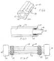
- Prosthesis 10 includes tubular conduit 12 having first and second ends 14 and 16 and a tubular channel 15 therebetween.
- Tubular prosthesis 10 may be a textile member formed from braided, knitted or woven synthetic yarns. Additionally, extruded tubes made from polytetrafluoroethylene (PTFE) and the like may also be used.
- PTFE polytetrafluoroethylene
- the prosthesis 10 may be formed from a polymer material such as polypropylene. While the above-described materials are examples of materials used to form tubular prosthesis 10, it is of course understood that the present invention may be formed of any suitable material.
- tubular prosthesis 10 may be radially compressed from the structure shown in Figure 1 so as to permit insertion into a delivery catheter for implantation within a body passageway such as a blood vessel, whereupon the prosthesis is expanded to its original form for secure deployment therein.
- tubular prosthesis 10 may be constructed to be of expandable material so that it is catheter-insertable in its original state and once positioned within the body passageway may be radially expanded (or radially self-expanded) for deployment in the vessel.
- Stent 28 is generally an annular member capable of radial expansion between a first diameter and a second diameter different from the first diameter.
- Stents such as these are well known in the art may be formed from materials such as stainless steel or other metals or alloys, polymeric materials or composites of polymers and metal and may be shaped in the form of springs, helically-wound coil springs, wire mesh or other structures and configurations. Coil springs and the like may also be manufactured from any expandable heat-sensitive material.
- U.S. Patent No. 4,655,771 discloses an expandable device made from woven stainless steel wire.
- Another example of an expandable stent is disclosed in U.S. Patent No. 3,868,956.
- the stent disclosed therein that is formed with a specific type of metal alloy displaying a memory function. That is, the alloy with which the stent is formed has the ability when compressed to recover its initial non-compressed shape upon heating.
- Such a stent can be compressed, inserted into and transported within a blood vessel to a desired position. Once in position, the stent can be heated for expansion to its original non-compressed state.
- a wire mesh stent is shown.
- the stent 28 is capable of being radially compressed from the condition shown in Figures 2 and 3 so that it may be intraluminally deployed along with or subsequent to insertion of tubular prosthesis 10. While a compressible stent is shown, it is contemplated that a stent which is radially expandable from an original state may also be employed.
- tubular prosthesis 10 includes longitudinally extending ribs 18 ( Figure 5) to permit folding or radial contraction thereof for insertion of the prosthesis 10 into a blood vessel or other bodily passageway using a catheter, not shown.
- the tubular conduit 12 may also be formed with one or more longitudinal crimps, creases or the like to enable folding for insertion of the prosthesis into a blood vessel via a catheter.
- tubular prosthesis 10 includes a pair of cuffs 20 and 22 disposed respectively adjacent ends 14 and 16.
- the cuffs 20 and 22 may be free standing cuffs, formed by folding the ends of the tubular conduit 12 back externally over itself. It is also contemplated that the cuffs may be formed by turning inwardly the ends of conduit 12.
- the cuffs 20 and 22 may also be formed of separate, distinct portions of synthetic material which may be glued or sutured onto tubular conduit 12. Further, the cuffs may comprise a material, such as an elastomeric material that is different than the material comprising the conduit.
- Cuffs 20 and 22 include inwardly directed open ends 20a and 22a respectively which are wholly unobstructed for stent insertion.
- Open ended slots 24 and 26 are defined between the external surface of tubular conduit 12 and the internal surface of cuffs 20 and 22.
- the slots 24 and 26 house one or more stents, such as stent 28, used by the device to both support and seal the body vessel into which the tubular prosthesis 10 is inserted.
- the stents 28 may be used whether the present invention is used as an implantable prosthetic graft or an endoprosthesis.
- stents 28 within the slots 24 and 26 of tubular prosthesis 10 helps assure patency of the lumen of a blood vessel or other body passageway into which the prosthesis 10 is inserted at the exact place at which support is required.
- the prosthesis/stent combination assures a secure anchor of the prosthesis 10 to the inner lumen surface of the blood vessel due to the radially expansive properties of stent 28.
- Stent 28 provides more than means for improved support and anchoring properties for the invention. Stent 28 also provides a support structure that is never in direct contact with a body fluid passing through the intraluminal passageway into which it is installed. Accordingly, fibrin and thrombotic deposits, common in prior art support structures which are in direct contact with the blood after implantation, are minimized.
- the stent 28 may be inserted and positioned within either or both of cuffs 20 and 22 of prosthesis 10 before implantation. Alternatively, the stent may be inserted into the prosthesis via catheter after the prosthesis 10 has been implanted. If stents 28 are positioned within cuffs 20 and 22 prior to implantation then the stents may be radially compressed along with tubular conduit 12 for catheter deployment. However, as above mentioned, tubular body 12 with cuffs 20 and 22 may be intraluminally deployed first and then stents 28 may be inserted in a subsequent procedure. It is still further contemplated that in certain situations, the stents may be disposed over tubular conduit 12 such as shown in Figure 5, and then once deployed the stents may be inserted into cuffs 20 and 22.
- implantable tubular intraluminal prosthesis 10 may include longitudinal ribs 18 which permit prosthesis 10 to be in partially folded or radially collapsed as shown in Figure 6.
- Other techniques for collapsing prosthesis 10 may also be employed.
- the intraluminal prosthesis 10 In the radially collapsed state, where the tubular conduit 12 as well as cuffs 20 and 22 are collapsed, the intraluminal prosthesis 10 can negotiate curves or bends of a blood vessel or other body passageway in which it is implanted and transported.
- the device may be inserted percutaneously (in its collapsed state) by use of a delivery catheter (not shown) and directed to a target area by any means or method known to those skilled in the art.
- conduit 12 and stents 28 When positioned, stent 28 and tubular conduit 12 are then radially expanded to return to the condition shown in Figures 4 and 5. Radial expansion of both conduit 12 and stents 28 may be accomplished with assistance of, for example, an expandable catheter balloon. It is also contemplated that the conduit 12 as well as stents 28 may be constructed to be radially self-expanding after deployment.
- the prosthesis As stents 28 are contained within the slots 24 and 26 outside the lumen of intraluminal prosthesis 10, the prosthesis has an almost infinitely variable and adjustable diameter in the ranges between the minimum and maximum diameter of the tubular conduit 12. Thus, the inner diameter of the lumen of the vessel in which the device is inserted need not be exactly known or predetermined.
- stent 28 is designed to radially expand with the force sufficient enough to anchor prosthesis 10 within a lumen 32 of a vessel 34 to form a liquid seal therein without placing disruptive force or undue pressure on the intraluminal walls. If it is determined that a more appropriately sized stent is necessary for a proper seal after insertion, the stent can be easily removed and replaced within the cuff by a better fitting stent without first excising the prosthesis. As the cuffs are generally flexible and complaint, they may accommodate a range of stent sizes as may be dictated by the particular application.
- Stent 28 is shown clearly supported in slot 24. Because the stent is enclosed between the prosthesis material of tubular body 12 and cuff material 20, the stent 28 is never in direct contact with either blood flowing through lumen 32 or the tissue of the walls of vessel 34. This is a marked improvement over conventional methods of using stents, normally attached using hooks or sutures directly to the luminal walls.
- the preferred embodiment of the present invention shows an endoprosthesis which is used to reinforce or buttress a body lumen
- the present invention may be practiced with a tubular graft which may be used to replace a missing section of a body lumen such as a blood vessel.
Abstract
Description
- The present invention relates generally to an implantable tubular prosthesis. More particularly the present invention relates to an implantable tubular prosthesis adapted to accommodate stents for supporting the prosthesis.
- The implantation of synthetic tubular prostheses to replace or buttress damaged or diseased vascular vessels or other luminal passageways within the human body is known. Synthetic tubular prostheses include grafts as well as endoprosthetic devices.
- Tubular prosthesis such as grafts, are typically implanted by surgical techniques. The surgeon would suture the graft in place in the blood vessel or other body passageway. Other endoprosthetic devices may be implanted intraluminally. These devices may be inserted percutaneously by use of a delivery catheter. Obviously, percutaneous catheter delivery permits implantation of a prosthesis without the need for major surgical intervention and the risks inherent therewith. The art therefore is moving toward the increased use of intraluminal implantation of various prosthetic devices. It has been found that under certain conditions, grafts as well as endoprosthetic devices may be implanted by means of a delivery catheter.
- With respect to grafts and other prostheses which may be traditionally surgically implanted, means other than suturing must be found to secure these prostheses in place in the body passageway in order to effectively permit intraluminal implantation. It has been known to employ stents in combination with grafts and various other prostheses to support and secure a prosthesis in place in the body passageway after implantation. Stents are typically radially expandable and/or contractible support members which are positioned inside of the graft or other tubular prosthesis and once the tubular prosthesis is properly positioned, the stent would be expanded to anchor the prosthesis within the body passageway.
- However, the use of stents to anchor prostheses is not without problems. Stents sometimes migrate with the flow of body fluid within a vessel if undersized or underexpanded. Also, thrombosis or fibrin buildup may occur within the stent diminishing patency of the intraluminal passageway when the stent is in direct contact with the blood.
- U.S. Patent No. 5,151,105 discloses an implantable, collapsible tubular prosthesis, i.e., graft, for surgical implantation within a vascular organ. The ends of the prosthesis include collapsible circular stents or annular balloons affixed thereto. The stents expand to seal the ends of the endo-vascular prosthesis to the inner luminal surface of the blood vessel into which the prosthesis is implanted. The stents may be sutured to the interior wall such that they are in direct contact with the body fluid therein, or may be placed within annular pockets. Because of the nature of the placement of the stent within the annular pocket, the insertion must take place before implantation. If problems arise surrounding the size of the stent, the tubular prosthesis into which the stent has been sealed must be replaced with a more closely fitting stent.
- U.S. Patent No. 4,728,328 discloses an implantable tubular prosthetic graft having prosthesis cuffs formed on distal ends of the graft. The cuffs are formed by folding the edges of the graft back over itself and bonding the turned back edges to the graft body. These cuffs are then used to suture the graft to the host vessel. Under certain conditions, however, grafts require greater support than that afforded by merely suturing through cuffs positioned at opposite ends of such graft. Also, the need for suturing would preclude catheter delivery.
- Accordingly, there is a need for an implantable tubular prosthesis which overcomes the aforementioned shortcomings of the prior art and provides a universal fitting means for cooperatively employing a stent in combination with the tubular prosthesis.
- According to one aspect of the present invention, there is provided an implantable prosthesis comprising:
a tubular conduit having an elongate body and opposed open ends, the conduit being capable of radial diametrical change between a first diameter and a second diameter;
an elongate cuff formed at one end region of the body; and
a variable diameter generally annular stent supported by the cuff. - According to another aspect of the present invention, there is provided a prosthesis for implantation within a body lumen comprising:
an elongate radially expandable tubular body;
a pair of cuffs, one cuff formed at each end region of the body; and
a pair of radially expandable stents, one stent being resident in each cuff of the pair of cuffs. - Preferably the or each cuff defines a partial enclosure with the body for enclosing the stent(s). Conveniently, the or each cuff has a closed end and an open end, thereby defining a slot for insertable accommodation of the stent.
- If desired, the tubular conduit includes a plurality of longitudinal ribs to permit radial contraction from the first diameter to the second diameter, to provide for intraluminal deployment. Moreover, conveniently the variable diameter stent is radially collapsible to permit intraluminal deployment thereof.
- Preferably the tubular conduit is radially expandable from the second diameter to the first diameter after the intraluminal deployment, and the stent is radially expandable after the intraluminal deployment.
- The tubular conduit may be formed of a textile fabric; or may be formed from polytetrafluoroethylene.
- The stent may be formed of a wire mesh.
- Conveniently the cuff is integrally formed with the tubular conduit, preferably with one or each end region of the tubular conduit being folded back, preferably externally, upon the body to form the cuff(s).
- Preferably the cuff is compliant to accommodate a stent within a range of different stent sizes.
- The present invention may include an implantable tubular prosthetic graft or may include an endoprosthetic or intraluminal device.
- The prosthesis of the present invention may be used in a method of implanting a prosthesis in a body vessel, comprising:
providing an elongate tubular conduit having a cuff at one end thereof;
implanting the tubular conduit in the body vessel;
inserting the stent in the cuff; and
expanding the stent within the cuff to anchor the one end of the tubular conduit in the body vessel. - The prosthesis of the present invention may be used in a method of repairing a damaged location of a body vessel, comprising the steps of:
providing an elongate tubular conduit having cuffs at the ends thereof;
providing a pair of expandable stents;
implanting the tubular conduit in the body vessel whereby the tubular conduit spans the damaged location;
inserting the stents in the cuffs; and
expanding the stents within the cuffs to anchor the tubular conduit in the body vessel adjacent each side of the damaged location. - The implanting step may include intraluminally delivering the tubular conduit.
- The inserting step may include intraluminally delivering the stent(s) to the cuff(s), and the inserting step may precede the implanting step, or the implanting step may precede the inserting step.
- The method may, wherein the tubular conduit is radially expandable, further include the step of radially expanding the tubular conduit.
- The method may further include, prior to the delivery step, collapsing the conduit.
- For a better understanding of the present invention and to show how the same may be carried into effect, reference will now be made, by way of example, to the accompanying drawings, in which:-
- Figure 1 is a perspective showing of a synthetic tubular prosthesis;
- Figures 2 and 3 are side elevational and front views respectively of a stent used in accordance with the present invention;
- Figure 4 shows in longitudinal cross-section the tubular prosthesis of figure 1 supporting a pair of stents shown in Figures 2 and 3;
- Figure 5 is a side elevational view of the combination shown in Figure 4;
- Figure 6 is a partial perspective showing of the prosthesis of Figures 4 and 5 shown in a partially collapsed condition; and
- Figure 7 is a partial sectional showing of the tubular prosthesis of the present invention implanted within a body vessel.
- The implantable tubular prosthesis having integral cuffs of this invention may be used as an intraluminal conduit or endoprosthesis for percutaneous implantation within a diseased or damaged blood vessel or other like vessel to provide reinforcement and support to the vessel. The implantable tubular prosthesis may also be used as a vascular graft to replace damaged or diseased portions of blood vessels or like fluid passageways. The present invention contemplates catheter delivery of the prosthesis, however the invention is not limited thereto.
- Referring to Figure 1, an implantable
tubular prosthesis 10 is shown.Prosthesis 10 includestubular conduit 12 having first and second ends 14 and 16 and atubular channel 15 therebetween.Tubular prosthesis 10 may be a textile member formed from braided, knitted or woven synthetic yarns. Additionally, extruded tubes made from polytetrafluoroethylene (PTFE) and the like may also be used. Preferably theprosthesis 10 may be formed from a polymer material such as polypropylene. While the above-described materials are examples of materials used to formtubular prosthesis 10, it is of course understood that the present invention may be formed of any suitable material. As will be described in further detail hereinbelow,tubular prosthesis 10 may be radially compressed from the structure shown in Figure 1 so as to permit insertion into a delivery catheter for implantation within a body passageway such as a blood vessel, whereupon the prosthesis is expanded to its original form for secure deployment therein. Alternatively,tubular prosthesis 10 may be constructed to be of expandable material so that it is catheter-insertable in its original state and once positioned within the body passageway may be radially expanded (or radially self-expanded) for deployment in the vessel. - Referring now to Figures 2 and 3, a
stent 28 is shown.Stent 28 is generally an annular member capable of radial expansion between a first diameter and a second diameter different from the first diameter. Stents such as these are well known in the art may be formed from materials such as stainless steel or other metals or alloys, polymeric materials or composites of polymers and metal and may be shaped in the form of springs, helically-wound coil springs, wire mesh or other structures and configurations. Coil springs and the like may also be manufactured from any expandable heat-sensitive material. - For example, U.S. Patent No. 4,655,771 discloses an expandable device made from woven stainless steel wire. Another example of an expandable stent is disclosed in U.S. Patent No. 3,868,956. The stent disclosed therein that is formed with a specific type of metal alloy displaying a memory function. That is, the alloy with which the stent is formed has the ability when compressed to recover its initial non-compressed shape upon heating. Such a stent can be compressed, inserted into and transported within a blood vessel to a desired position. Once in position, the stent can be heated for expansion to its original non-compressed state.
- In the present illustrative embodiment, a wire mesh stent is shown. The
stent 28 is capable of being radially compressed from the condition shown in Figures 2 and 3 so that it may be intraluminally deployed along with or subsequent to insertion oftubular prosthesis 10. While a compressible stent is shown, it is contemplated that a stent which is radially expandable from an original state may also be employed. - In the preferred embodiment of the present invention
tubular prosthesis 10 includes longitudinally extending ribs 18 (Figure 5) to permit folding or radial contraction thereof for insertion of theprosthesis 10 into a blood vessel or other bodily passageway using a catheter, not shown. Although not shown in Figure 1, thetubular conduit 12 may also be formed with one or more longitudinal crimps, creases or the like to enable folding for insertion of the prosthesis into a blood vessel via a catheter. - Referring now to Figures 4 and 5, in accordance with the present invention
tubular prosthesis 10 includes a pair ofcuffs cuffs tubular conduit 12 back externally over itself. It is also contemplated that the cuffs may be formed by turning inwardly the ends ofconduit 12. Thecuffs tubular conduit 12. Further, the cuffs may comprise a material, such as an elastomeric material that is different than the material comprising the conduit.Cuffs open ends 20a and 22a respectively which are wholly unobstructed for stent insertion. Open endedslots 24 and 26 are defined between the external surface oftubular conduit 12 and the internal surface ofcuffs slots 24 and 26 house one or more stents, such asstent 28, used by the device to both support and seal the body vessel into which thetubular prosthesis 10 is inserted. Thestents 28 may be used whether the present invention is used as an implantable prosthetic graft or an endoprosthesis. - The accommodation of
stents 28 within theslots 24 and 26 oftubular prosthesis 10 helps assure patency of the lumen of a blood vessel or other body passageway into which theprosthesis 10 is inserted at the exact place at which support is required. The prosthesis/stent combination assures a secure anchor of theprosthesis 10 to the inner lumen surface of the blood vessel due to the radially expansive properties ofstent 28. -
Stent 28 provides more than means for improved support and anchoring properties for the invention.Stent 28 also provides a support structure that is never in direct contact with a body fluid passing through the intraluminal passageway into which it is installed. Accordingly, fibrin and thrombotic deposits, common in prior art support structures which are in direct contact with the blood after implantation, are minimized. - The
stent 28 may be inserted and positioned within either or both ofcuffs prosthesis 10 before implantation. Alternatively, the stent may be inserted into the prosthesis via catheter after theprosthesis 10 has been implanted. Ifstents 28 are positioned withincuffs tubular conduit 12 for catheter deployment. However, as above mentioned,tubular body 12 withcuffs stents 28 may be inserted in a subsequent procedure. It is still further contemplated that in certain situations, the stents may be disposed overtubular conduit 12 such as shown in Figure 5, and then once deployed the stents may be inserted intocuffs - As mentioned above, implantable tubular
intraluminal prosthesis 10 may includelongitudinal ribs 18 which permitprosthesis 10 to be in partially folded or radially collapsed as shown in Figure 6. Other techniques for collapsingprosthesis 10 may also be employed. In the radially collapsed state, where thetubular conduit 12 as well ascuffs intraluminal prosthesis 10 can negotiate curves or bends of a blood vessel or other body passageway in which it is implanted and transported. The device may be inserted percutaneously (in its collapsed state) by use of a delivery catheter (not shown) and directed to a target area by any means or method known to those skilled in the art. When positioned,stent 28 andtubular conduit 12 are then radially expanded to return to the condition shown in Figures 4 and 5. Radial expansion of bothconduit 12 andstents 28 may be accomplished with assistance of, for example, an expandable catheter balloon. It is also contemplated that theconduit 12 as well asstents 28 may be constructed to be radially self-expanding after deployment. - As
stents 28 are contained within theslots 24 and 26 outside the lumen ofintraluminal prosthesis 10, the prosthesis has an almost infinitely variable and adjustable diameter in the ranges between the minimum and maximum diameter of thetubular conduit 12. Thus, the inner diameter of the lumen of the vessel in which the device is inserted need not be exactly known or predetermined. - Referring to Figure 7,
stent 28 is designed to radially expand with the force sufficient enough to anchorprosthesis 10 within alumen 32 of avessel 34 to form a liquid seal therein without placing disruptive force or undue pressure on the intraluminal walls. If it is determined that a more appropriately sized stent is necessary for a proper seal after insertion, the stent can be easily removed and replaced within the cuff by a better fitting stent without first excising the prosthesis. As the cuffs are generally flexible and complaint, they may accommodate a range of stent sizes as may be dictated by the particular application. -
Stent 28 is shown clearly supported inslot 24. Because the stent is enclosed between the prosthesis material oftubular body 12 andcuff material 20, thestent 28 is never in direct contact with either blood flowing throughlumen 32 or the tissue of the walls ofvessel 34. This is a marked improvement over conventional methods of using stents, normally attached using hooks or sutures directly to the luminal walls. - As mentioned above, while the preferred embodiment of the present invention shows an endoprosthesis which is used to reinforce or buttress a body lumen, it is also contemplated that the present invention may be practiced with a tubular graft which may be used to replace a missing section of a body lumen such as a blood vessel.
- Thus, while the above embodiments have been disclosed, other and further manifestations of the present invention will become apparent to those skilled in the art. It is intended to claim all such changes and modifications which come within the true scope and spirit of the present invention.
Claims (10)
- An implantable prosthesis comprising:
a tubular conduit having an elongate body and opposed open ends, the conduit being capable of radial diametrical change between a first diameter and a second diameter;
an elongate cuff formed at one end region of the body; and
a variable diameter generally annular stent supported by the cuff. - An implantable prosthesis according to claim 1, wherein the cuff defines a partial enclosure with the body for enclosing the stent.
- An implantable prosthesis according to claim 1 or 2, wherein the cuff has a closed end and an open end, thereby defining a slot for insertable accommodation of the stent.
- An implantable prosthesis according to claim 1, 2 or 3, wherein the tubular conduit includes a plurality of longitudinal ribs to permit radial contraction from the first diameter to the second diameter, in order to provide for intraluminal deployment.
- An implantable prosthesis according to any preceding claims, wherein the tubular conduit is formed of a textile fabric.
- An implantable prosthesis according to any one of claims 1 to 4, wherein the tubular conduit is formed from polytetrafluoroethylene.
- An implantable prosthesis according to any preceding claim, wherein the cuff is integrally formed with the tubular conduit.
- An implantable prosthesis according to claim 7, wherein the one end of the tubular conduit is folded externally over the body.
- An implantable prosthesis according to claim 7 wherein the one end of the tubular conduit is folded externally over the body.
- An implantable prosthesis according to any preceding claim, wherein the other end of the tubular conduit includes a cuff.
Applications Claiming Priority (2)
| Application Number | Priority Date | Filing Date | Title |
|---|---|---|---|
| US267468 | 1994-06-28 | ||
| US08/267,468 US5522881A (en) | 1994-06-28 | 1994-06-28 | Implantable tubular prosthesis having integral cuffs |
Publications (3)
| Publication Number | Publication Date |
|---|---|
| EP0689806A2 true EP0689806A2 (en) | 1996-01-03 |
| EP0689806A3 EP0689806A3 (en) | 1997-06-25 |
| EP0689806B1 EP0689806B1 (en) | 2003-08-27 |
Family
ID=23018906
Family Applications (1)
| Application Number | Title | Priority Date | Filing Date |
|---|---|---|---|
| EP95303233A Expired - Lifetime EP0689806B1 (en) | 1994-06-28 | 1995-05-12 | Implantable tubular prosthesis having cuffs |
Country Status (7)
| Country | Link |
|---|---|
| US (1) | US5522881A (en) |
| EP (1) | EP0689806B1 (en) |
| JP (1) | JP3686704B2 (en) |
| AU (1) | AU685579B2 (en) |
| CA (1) | CA2146057C (en) |
| DE (1) | DE69531573T2 (en) |
| FI (1) | FI953185A (en) |
Cited By (34)
| Publication number | Priority date | Publication date | Assignee | Title |
|---|---|---|---|---|
| WO1996027347A1 (en) * | 1995-03-08 | 1996-09-12 | Board Of Governers Of Wayne State University | Composite intraluminal graft |
| US5709713A (en) * | 1995-03-31 | 1998-01-20 | Cardiovascular Concepts, Inc. | Radially expansible vascular prosthesis having reversible and other locking structures |
| US5769882A (en) * | 1995-09-08 | 1998-06-23 | Medtronic, Inc. | Methods and apparatus for conformably sealing prostheses within body lumens |
| WO1998027895A1 (en) * | 1996-12-23 | 1998-07-02 | Prograft Medical, Inc. | Endolumenal stent-graft with leak-resistant seal |
| US5824037A (en) * | 1995-10-03 | 1998-10-20 | Medtronic, Inc. | Modular intraluminal prostheses construction and methods |
| US5843158A (en) * | 1996-01-05 | 1998-12-01 | Medtronic, Inc. | Limited expansion endoluminal prostheses and methods for their use |
| WO1999039662A1 (en) * | 1998-02-09 | 1999-08-12 | Triad Vascular Systems, Inc. | Endovascular graft |
| US6110198A (en) * | 1995-10-03 | 2000-08-29 | Medtronic Inc. | Method for deploying cuff prostheses |
| US6176875B1 (en) | 1996-01-05 | 2001-01-23 | Medtronic, Inc. | Limited expansion endoluminal prostheses and methods for their use |
| US6327772B1 (en) | 1996-01-30 | 2001-12-11 | Medtronic, Inc. | Method for fabricating a planar eversible lattice which forms a stent when everted |
| EP1175875A2 (en) * | 1994-10-04 | 2002-01-30 | Surgical Innovations V.o.f. | Assembly for treating blood vessels |
| US6352561B1 (en) | 1996-12-23 | 2002-03-05 | W. L. Gore & Associates | Implant deployment apparatus |
| WO2003003945A3 (en) * | 2001-07-03 | 2003-06-19 | Scimed Life Systems Inc | Implant having means for fixation to a body lumen and method for implanting the same |
| EP1363560A2 (en) * | 2001-01-19 | 2003-11-26 | Walid Najib Aboul-Hosn | Apparatus and method for maintaining flow through a vessel or duct |
| EP1584304A1 (en) * | 2004-04-08 | 2005-10-12 | KRAUTH medical KG (GmbH & Co.) | A conduit for introducing into a blood vessel |
| WO2006002386A1 (en) * | 2004-06-24 | 2006-01-05 | Boston Scientific Scimed, Inc. | Implantable prosthesis having reinforced attachment sites |
| WO2008069648A1 (en) * | 2006-10-26 | 2008-06-12 | Vascu-Snap B.V. | Vascular prosthesis |
| US7682380B2 (en) | 1996-12-23 | 2010-03-23 | Gore Enterprise Holdings, Inc. | Kink-resistant bifurcated prosthesis |
| US7766954B2 (en) | 2001-12-20 | 2010-08-03 | Trivascular2, Inc. | Advanced endovascular graft |
| US7803178B2 (en) | 2004-01-30 | 2010-09-28 | Trivascular, Inc. | Inflatable porous implants and methods for drug delivery |
| US8157940B2 (en) | 1995-03-10 | 2012-04-17 | Bard Peripheral Vascular, Inc. | Methods for making a supported graft |
| US8236040B2 (en) | 2008-04-11 | 2012-08-07 | Endologix, Inc. | Bifurcated graft deployment systems and methods |
| US8617441B2 (en) | 1995-03-10 | 2013-12-31 | Bard Peripheral Vascular, Inc. | Methods for making an encapsulated stent |
| US8617337B2 (en) | 1999-02-02 | 2013-12-31 | Bard Peripheral Vascular, Inc. | Partial encapsulation of stents |
| US8623065B2 (en) | 1994-08-31 | 2014-01-07 | W. L. Gore & Associates, Inc. | Exterior supported self-expanding stent-graft |
| US9687374B2 (en) | 2011-03-01 | 2017-06-27 | Endologix, Inc. | Catheter system and methods of using same |
| US9700701B2 (en) | 2008-07-01 | 2017-07-11 | Endologix, Inc. | Catheter system and methods of using same |
| US9757262B2 (en) | 2009-07-15 | 2017-09-12 | Endologix, Inc. | Stent graft |
| US9907642B2 (en) | 2009-07-27 | 2018-03-06 | Endologix, Inc. | Stent graft |
| EP2578249A3 (en) * | 2010-07-02 | 2018-03-07 | Nikkiso Co., Ltd. | Artificial blood vessel and access port of artificial blood vessel |
| US10245166B2 (en) | 2008-02-22 | 2019-04-02 | Endologix, Inc. | Apparatus and method of placement of a graft or graft system |
| US10772717B2 (en) | 2009-05-01 | 2020-09-15 | Endologix, Inc. | Percutaneous method and device to treat dissections |
| US11129737B2 (en) | 2015-06-30 | 2021-09-28 | Endologix Llc | Locking assembly for coupling guidewire to delivery system |
| US11406518B2 (en) | 2010-11-02 | 2022-08-09 | Endologix Llc | Apparatus and method of placement of a graft or graft system |
Families Citing this family (251)
| Publication number | Priority date | Publication date | Assignee | Title |
|---|---|---|---|---|
| US5632772A (en) * | 1993-10-21 | 1997-05-27 | Corvita Corporation | Expandable supportive branched endoluminal grafts |
| US6165210A (en) | 1994-04-01 | 2000-12-26 | Gore Enterprise Holdings, Inc. | Self-expandable helical intravascular stent and stent-graft |
| US6001123A (en) | 1994-04-01 | 1999-12-14 | Gore Enterprise Holdings Inc. | Folding self-expandable intravascular stent-graft |
| US6015429A (en) | 1994-09-08 | 2000-01-18 | Gore Enterprise Holdings, Inc. | Procedures for introducing stents and stent-grafts |
| US5702419A (en) * | 1994-09-21 | 1997-12-30 | Wake Forest University | Expandable, intraluminal stents |
| US5755770A (en) * | 1995-01-31 | 1998-05-26 | Boston Scientific Corporatiion | Endovascular aortic graft |
| US6579314B1 (en) | 1995-03-10 | 2003-06-17 | C.R. Bard, Inc. | Covered stent with encapsulated ends |
| US5728131A (en) * | 1995-06-12 | 1998-03-17 | Endotex Interventional Systems, Inc. | Coupling device and method of use |
| EP0866677A4 (en) | 1995-12-14 | 1999-10-27 | Prograft Medical Inc | Stent-graft deployment apparatus and method |
| US6042605A (en) | 1995-12-14 | 2000-03-28 | Gore Enterprose Holdings, Inc. | Kink resistant stent-graft |
| US5928279A (en) | 1996-07-03 | 1999-07-27 | Baxter International Inc. | Stented, radially expandable, tubular PTFE grafts |
| DE69734667T2 (en) | 1996-09-26 | 2006-06-08 | Boston Scientific Scimed, Inc., Maple Grove | COMBINED MEDICAL DEVICE CONSISTING OF A SUPPORT STRUCTURE AND A MEMBRANE |
| US5824046A (en) * | 1996-09-27 | 1998-10-20 | Scimed Life Systems, Inc. | Covered stent |
| US5755778A (en) * | 1996-10-16 | 1998-05-26 | Nitinol Medical Technologies, Inc. | Anastomosis device |
| US6315791B1 (en) * | 1996-12-03 | 2001-11-13 | Atrium Medical Corporation | Self-expanding prothesis |
| US5925074A (en) * | 1996-12-03 | 1999-07-20 | Atrium Medical Corporation | Vascular endoprosthesis and method |
| US6010529A (en) * | 1996-12-03 | 2000-01-04 | Atrium Medical Corporation | Expandable shielded vessel support |
| US5925061A (en) | 1997-01-13 | 1999-07-20 | Gore Enterprise Holdings, Inc. | Low profile vascular stent |
| US5843166A (en) * | 1997-01-17 | 1998-12-01 | Meadox Medicals, Inc. | Composite graft-stent having pockets for accomodating movement |
| US5961545A (en) * | 1997-01-17 | 1999-10-05 | Meadox Medicals, Inc. | EPTFE graft-stent composite device |
| US6951572B1 (en) | 1997-02-20 | 2005-10-04 | Endologix, Inc. | Bifurcated vascular graft and method and apparatus for deploying same |
| US6090128A (en) * | 1997-02-20 | 2000-07-18 | Endologix, Inc. | Bifurcated vascular graft deployment device |
| ATE287679T1 (en) | 1997-03-05 | 2005-02-15 | Boston Scient Ltd | COMPLIANT MULTI-LAYER STENT DEVICE |
| US5855597A (en) * | 1997-05-07 | 1999-01-05 | Iowa-India Investments Co. Limited | Stent valve and stent graft for percutaneous surgery |
| US6258120B1 (en) * | 1997-12-23 | 2001-07-10 | Embol-X, Inc. | Implantable cerebral protection device and methods of use |
| US5944750A (en) * | 1997-06-30 | 1999-08-31 | Eva Corporation | Method and apparatus for the surgical repair of aneurysms |
| US5954766A (en) * | 1997-09-16 | 1999-09-21 | Zadno-Azizi; Gholam-Reza | Body fluid flow control device |
| NL1007349C2 (en) | 1997-10-24 | 1999-04-27 | Suyker Wilhelmus Joseph Leonardus | System for the mechanical production of anastomoses between hollow structures; as well as device and applicator for use therewith. |
| IT1296692B1 (en) * | 1997-11-18 | 1999-07-14 | Bidoia Sas Di Gianfranco Bidoi | DEVICE TO PROTECT TISSUES OF PHYSIOLOGICAL CONDUCTS DURING EXPLORATIONS WITH DIAGNOSTIC AND/OR OPERATIONAL INSTRUMENTS |
| US6077296A (en) * | 1998-03-04 | 2000-06-20 | Endologix, Inc. | Endoluminal vascular prosthesis |
| US6176864B1 (en) * | 1998-03-09 | 2001-01-23 | Corvascular, Inc. | Anastomosis device and method |
| US6241741B1 (en) | 1998-03-09 | 2001-06-05 | Corvascular Surgical Systems, Inc. | Anastomosis device and method |
| US6110188A (en) * | 1998-03-09 | 2000-08-29 | Corvascular, Inc. | Anastomosis method |
| US7491232B2 (en) * | 1998-09-18 | 2009-02-17 | Aptus Endosystems, Inc. | Catheter-based fastener implantation apparatus and methods with implantation force resolution |
| US7500988B1 (en) * | 2000-11-16 | 2009-03-10 | Cordis Corporation | Stent for use in a stent graft |
| US6887268B2 (en) * | 1998-03-30 | 2005-05-03 | Cordis Corporation | Extension prosthesis for an arterial repair |
| US5989287A (en) * | 1998-05-06 | 1999-11-23 | Av Healing Llc | Vascular graft assemblies and methods for implanting same |
| US6099559A (en) * | 1998-05-28 | 2000-08-08 | Medtronic Ave, Inc. | Endoluminal support assembly with capped ends |
| AU4323199A (en) * | 1998-06-19 | 2000-01-05 | Endologix, Inc. | Self expanding bifurcated endovascular prosthesis |
| US6143022A (en) * | 1998-08-24 | 2000-11-07 | Medtronic Ave, Inc. | Stent-graft assembly with dual configuration graft component and method of manufacture |
| US6168619B1 (en) * | 1998-10-16 | 2001-01-02 | Quanam Medical Corporation | Intravascular stent having a coaxial polymer member and end sleeves |
| US6187036B1 (en) | 1998-12-11 | 2001-02-13 | Endologix, Inc. | Endoluminal vascular prosthesis |
| DE69927055T2 (en) | 1998-12-11 | 2006-06-29 | Endologix, Inc., Irvine | ENDOLUMINAL VASCULAR PROSTHESIS |
| US6197049B1 (en) | 1999-02-17 | 2001-03-06 | Endologix, Inc. | Articulating bifurcation graft |
| US6733523B2 (en) | 1998-12-11 | 2004-05-11 | Endologix, Inc. | Implantable vascular graft |
| US6660030B2 (en) | 1998-12-11 | 2003-12-09 | Endologix, Inc. | Bifurcation graft deployment catheter |
| CA2348523C (en) * | 1998-12-16 | 2008-02-12 | Cook Incorporated | Finishing technique for a guiding catheter |
| US6558414B2 (en) * | 1999-02-02 | 2003-05-06 | Impra, Inc. | Partial encapsulation of stents using strips and bands |
| US6261316B1 (en) * | 1999-03-11 | 2001-07-17 | Endologix, Inc. | Single puncture bifurcation graft deployment system |
| US8034100B2 (en) | 1999-03-11 | 2011-10-11 | Endologix, Inc. | Graft deployment system |
| US6287335B1 (en) * | 1999-04-26 | 2001-09-11 | William J. Drasler | Intravascular folded tubular endoprosthesis |
| US6221079B1 (en) * | 1999-08-31 | 2001-04-24 | Cardiac Assist Technologies, Inc. | Method and apparatus for vessel repair in a patient |
| US6475235B1 (en) | 1999-11-16 | 2002-11-05 | Iowa-India Investments Company, Limited | Encapsulated stent preform |
| US10172730B2 (en) * | 1999-11-19 | 2019-01-08 | Vactronix Scientific, Llc | Stents with metallic covers and methods of making same |
| US20030130671A1 (en) * | 1999-11-23 | 2003-07-10 | Duhaylongsod Francis G. | Anastomosis device and method |
| US8474460B2 (en) * | 2000-03-04 | 2013-07-02 | Pulmonx Corporation | Implanted bronchial isolation devices and methods |
| EP1267748B1 (en) * | 2000-03-09 | 2006-06-28 | Design & Performance - Cyprus Limited | Stent with cover connectors |
| US6454799B1 (en) | 2000-04-06 | 2002-09-24 | Edwards Lifesciences Corporation | Minimally-invasive heart valves and methods of use |
| US6729356B1 (en) | 2000-04-27 | 2004-05-04 | Endovascular Technologies, Inc. | Endovascular graft for providing a seal with vasculature |
| US20030114918A1 (en) | 2000-04-28 | 2003-06-19 | Garrison Michi E. | Stent graft assembly and method |
| US7135037B1 (en) * | 2000-05-01 | 2006-11-14 | Endovascular Technologies, Inc. | System and method for forming a junction between elements of a modular endovascular prosthesis |
| CA2403276C (en) * | 2000-05-04 | 2009-10-20 | Oregon Health Sciences University | Endovascular stent graft |
| US6808533B1 (en) | 2000-07-28 | 2004-10-26 | Atrium Medical Corporation | Covered stent and method of covering a stent |
| CA2419811A1 (en) | 2000-08-18 | 2002-02-28 | Atritech, Inc. | Expandable implant devices for filtering blood flow from atrial appendages |
| US6652574B1 (en) | 2000-09-28 | 2003-11-25 | Vascular Concepts Holdings Limited | Product and process for manufacturing a wire stent coated with a biocompatible fluoropolymer |
| US6966917B1 (en) | 2000-11-09 | 2005-11-22 | Innovation Interventional Technologies B.V. | Deformable connector for mechanically connecting hollow structures |
| US6494909B2 (en) * | 2000-12-01 | 2002-12-17 | Prodesco, Inc. | Endovascular valve |
| US6773456B1 (en) | 2001-03-23 | 2004-08-10 | Endovascular Technologies, Inc. | Adjustable customized endovascular graft |
| US6786919B1 (en) * | 2001-07-10 | 2004-09-07 | Endovascular Technologies, Inc. | Self-expanding intravascular device with protector members |
| US6767359B2 (en) * | 2001-09-28 | 2004-07-27 | Ethicon, Inc. | Prosthesis for the repair of thoracic or abdominal aortic aneurysms and method therefor |
| US7192441B2 (en) * | 2001-10-16 | 2007-03-20 | Scimed Life Systems, Inc. | Aortic artery aneurysm endovascular prosthesis |
| US7033389B2 (en) * | 2001-10-16 | 2006-04-25 | Scimed Life Systems, Inc. | Tubular prosthesis for external agent delivery |
| US20050070992A1 (en) * | 2001-11-28 | 2005-03-31 | Aptus Endosystems, Inc. | Prosthesis systems and methods sized and configured for the receipt and retention of fasteners |
| US20050177180A1 (en) | 2001-11-28 | 2005-08-11 | Aptus Endosystems, Inc. | Devices, systems, and methods for supporting tissue and/or structures within a hollow body organ |
| US9320503B2 (en) | 2001-11-28 | 2016-04-26 | Medtronic Vascular, Inc. | Devices, system, and methods for guiding an operative tool into an interior body region |
| US20090112303A1 (en) * | 2001-11-28 | 2009-04-30 | Lee Bolduc | Devices, systems, and methods for endovascular staple and/or prosthesis delivery and implantation |
| US8231639B2 (en) | 2001-11-28 | 2012-07-31 | Aptus Endosystems, Inc. | Systems and methods for attaching a prosthesis within a body lumen or hollow organ |
| US20070073389A1 (en) | 2001-11-28 | 2007-03-29 | Aptus Endosystems, Inc. | Endovascular aneurysm devices, systems, and methods |
| EP1448117B1 (en) | 2001-11-28 | 2013-05-22 | Aptus Endosystems, Inc. | Endovascular aneurysm repair system |
| US7125464B2 (en) | 2001-12-20 | 2006-10-24 | Boston Scientific Santa Rosa Corp. | Method for manufacturing an endovascular graft section |
| US6776604B1 (en) * | 2001-12-20 | 2004-08-17 | Trivascular, Inc. | Method and apparatus for shape forming endovascular graft material |
| US7090693B1 (en) | 2001-12-20 | 2006-08-15 | Boston Scientific Santa Rosa Corp. | Endovascular graft joint and method for manufacture |
| US8308797B2 (en) | 2002-01-04 | 2012-11-13 | Colibri Heart Valve, LLC | Percutaneously implantable replacement heart valve device and method of making same |
| US20040210300A1 (en) * | 2002-01-19 | 2004-10-21 | Aboul-Hosn Walid Najib | Apparatus and method for maintaining flow through a vessel or duct |
| US7326245B2 (en) * | 2002-01-31 | 2008-02-05 | Boston Scientific Scimed, Inc. | Medical device for delivering biologically active material |
| US7445629B2 (en) * | 2002-01-31 | 2008-11-04 | Boston Scientific Scimed, Inc. | Medical device for delivering biologically active material |
| US20030171801A1 (en) * | 2002-03-06 | 2003-09-11 | Brian Bates | Partially covered intraluminal support device |
| US20030204248A1 (en) * | 2002-03-25 | 2003-10-30 | Murphy Kieran P. | Device viewable under an imaging beam |
| US7927368B2 (en) * | 2002-03-25 | 2011-04-19 | Kieran Murphy Llc | Device viewable under an imaging beam |
| US9375203B2 (en) | 2002-03-25 | 2016-06-28 | Kieran Murphy Llc | Biopsy needle |
| US20030181810A1 (en) | 2002-03-25 | 2003-09-25 | Murphy Kieran P. | Kit for image guided surgical procedures |
| US7044962B2 (en) * | 2002-06-25 | 2006-05-16 | Scimed Life Systems, Inc. | Implantable prosthesis with displaceable skirt |
| US8105373B2 (en) * | 2002-12-16 | 2012-01-31 | Boston Scientific Scimed, Inc. | Flexible stent with improved axial strength |
| US9333102B2 (en) * | 2003-02-24 | 2016-05-10 | Allium Medical Solutions Ltd. | Stent |
| US7377937B2 (en) * | 2003-04-22 | 2008-05-27 | Medtronic Vascular, Inc. | Stent-graft assembly with elution openings |
| US20040225349A1 (en) * | 2003-05-09 | 2004-11-11 | Thistle Robert C. | Eversible locking mechanism for modular stents |
| KR100561713B1 (en) * | 2003-05-23 | 2006-03-20 | (주) 태웅메디칼 | Flexible self-expandable stent and methods for making the stent |
| US7763063B2 (en) | 2003-09-03 | 2010-07-27 | Bolton Medical, Inc. | Self-aligning stent graft delivery system, kit, and method |
| US9198786B2 (en) | 2003-09-03 | 2015-12-01 | Bolton Medical, Inc. | Lumen repair device with capture structure |
| US8292943B2 (en) | 2003-09-03 | 2012-10-23 | Bolton Medical, Inc. | Stent graft with longitudinal support member |
| US11596537B2 (en) | 2003-09-03 | 2023-03-07 | Bolton Medical, Inc. | Delivery system and method for self-centering a proximal end of a stent graft |
| US20080264102A1 (en) | 2004-02-23 | 2008-10-30 | Bolton Medical, Inc. | Sheath Capture Device for Stent Graft Delivery System and Method for Operating Same |
| US20070198078A1 (en) | 2003-09-03 | 2007-08-23 | Bolton Medical, Inc. | Delivery system and method for self-centering a Proximal end of a stent graft |
| US11259945B2 (en) | 2003-09-03 | 2022-03-01 | Bolton Medical, Inc. | Dual capture device for stent graft delivery system and method for capturing a stent graft |
| US8500792B2 (en) | 2003-09-03 | 2013-08-06 | Bolton Medical, Inc. | Dual capture device for stent graft delivery system and method for capturing a stent graft |
| US20050060020A1 (en) * | 2003-09-17 | 2005-03-17 | Scimed Life Systems, Inc. | Covered stent with biologically active material |
| US7056286B2 (en) | 2003-11-12 | 2006-06-06 | Adrian Ravenscroft | Medical device anchor and delivery system |
| US7338530B2 (en) * | 2003-11-24 | 2008-03-04 | Checkmed Systems, Inc. | Stent |
| US8840663B2 (en) | 2003-12-23 | 2014-09-23 | Sadra Medical, Inc. | Repositionable heart valve method |
| US7381219B2 (en) | 2003-12-23 | 2008-06-03 | Sadra Medical, Inc. | Low profile heart valve and delivery system |
| US11278398B2 (en) | 2003-12-23 | 2022-03-22 | Boston Scientific Scimed, Inc. | Methods and apparatus for endovascular heart valve replacement comprising tissue grasping elements |
| US8343213B2 (en) | 2003-12-23 | 2013-01-01 | Sadra Medical, Inc. | Leaflet engagement elements and methods for use thereof |
| US20120041550A1 (en) | 2003-12-23 | 2012-02-16 | Sadra Medical, Inc. | Methods and Apparatus for Endovascular Heart Valve Replacement Comprising Tissue Grasping Elements |
| US7988724B2 (en) | 2003-12-23 | 2011-08-02 | Sadra Medical, Inc. | Systems and methods for delivering a medical implant |
| US8052749B2 (en) | 2003-12-23 | 2011-11-08 | Sadra Medical, Inc. | Methods and apparatus for endovascular heart valve replacement comprising tissue grasping elements |
| US20050178389A1 (en) * | 2004-01-27 | 2005-08-18 | Shaw David P. | Disease indications for selective endobronchial lung region isolation |
| US8206684B2 (en) * | 2004-02-27 | 2012-06-26 | Pulmonx Corporation | Methods and devices for blocking flow through collateral pathways in the lung |
| WO2005087137A1 (en) * | 2004-03-08 | 2005-09-22 | Emphasys Medical, Inc. | Implanted bronchial isolation devices and methods |
| US8398670B2 (en) * | 2004-03-19 | 2013-03-19 | Aga Medical Corporation | Multi-layer braided structures for occluding vascular defects and for occluding fluid flow through portions of the vasculature of the body |
| US8313505B2 (en) * | 2004-03-19 | 2012-11-20 | Aga Medical Corporation | Device for occluding vascular defects |
| US8747453B2 (en) * | 2008-02-18 | 2014-06-10 | Aga Medical Corporation | Stent/stent graft for reinforcement of vascular abnormalities and associated method |
| US8777974B2 (en) | 2004-03-19 | 2014-07-15 | Aga Medical Corporation | Multi-layer braided structures for occluding vascular defects |
| US9039724B2 (en) * | 2004-03-19 | 2015-05-26 | Aga Medical Corporation | Device for occluding vascular defects |
| US20050216043A1 (en) * | 2004-03-26 | 2005-09-29 | Blatter Duane D | Stented end graft vessel device for anastomosis and related methods for percutaneous placement |
| US20050283226A1 (en) * | 2004-06-18 | 2005-12-22 | Scimed Life Systems, Inc. | Medical devices |
| US20060030863A1 (en) * | 2004-07-21 | 2006-02-09 | Fields Antony J | Implanted bronchial isolation device delivery devices and methods |
| US7515970B2 (en) | 2004-08-18 | 2009-04-07 | Cardiac Pacemakers, Inc. | Transeptal lead |
| US8795315B2 (en) | 2004-10-06 | 2014-08-05 | Cook Medical Technologies Llc | Emboli capturing device having a coil and method for capturing emboli |
| US9211181B2 (en) | 2004-11-19 | 2015-12-15 | Pulmonx Corporation | Implant loading device and system |
| US7771472B2 (en) * | 2004-11-19 | 2010-08-10 | Pulmonx Corporation | Bronchial flow control devices and methods of use |
| US7306623B2 (en) * | 2005-01-13 | 2007-12-11 | Medtronic Vascular, Inc. | Branch vessel graft design and deployment method |
| DE102005003632A1 (en) | 2005-01-20 | 2006-08-17 | Fraunhofer-Gesellschaft zur Förderung der angewandten Forschung e.V. | Catheter for the transvascular implantation of heart valve prostheses |
| US8221446B2 (en) * | 2005-03-15 | 2012-07-17 | Cook Medical Technologies | Embolic protection device |
| US8945169B2 (en) | 2005-03-15 | 2015-02-03 | Cook Medical Technologies Llc | Embolic protection device |
| US8663312B2 (en) | 2005-05-27 | 2014-03-04 | Hlt, Inc. | Intravascular cuff |
| AU2006275881B2 (en) * | 2005-07-27 | 2012-04-12 | Cook Medical Technologies Llc | Stent/graft device and method for open surgical placement |
| US8187298B2 (en) | 2005-08-04 | 2012-05-29 | Cook Medical Technologies Llc | Embolic protection device having inflatable frame |
| US20070050013A1 (en) * | 2005-09-01 | 2007-03-01 | Jeffrey M. Gross | Venous valve prosthesis and method of fabrication |
| US8377092B2 (en) * | 2005-09-16 | 2013-02-19 | Cook Medical Technologies Llc | Embolic protection device |
| US7569071B2 (en) | 2005-09-21 | 2009-08-04 | Boston Scientific Scimed, Inc. | Venous valve, system, and method with sinus pocket |
| US8632562B2 (en) | 2005-10-03 | 2014-01-21 | Cook Medical Technologies Llc | Embolic protection device |
| US8182508B2 (en) | 2005-10-04 | 2012-05-22 | Cook Medical Technologies Llc | Embolic protection device |
| US8252017B2 (en) | 2005-10-18 | 2012-08-28 | Cook Medical Technologies Llc | Invertible filter for embolic protection |
| CN101466316B (en) | 2005-10-20 | 2012-06-27 | 阿普特斯内系统公司 | Devices systems and methods for prosthesis delivery and implantation including the use of a fastener tool |
| US8216269B2 (en) * | 2005-11-02 | 2012-07-10 | Cook Medical Technologies Llc | Embolic protection device having reduced profile |
| US8152831B2 (en) | 2005-11-17 | 2012-04-10 | Cook Medical Technologies Llc | Foam embolic protection device |
| US20070213813A1 (en) | 2005-12-22 | 2007-09-13 | Symetis Sa | Stent-valves for valve replacement and associated methods and systems for surgery |
| US9375215B2 (en) * | 2006-01-20 | 2016-06-28 | W. L. Gore & Associates, Inc. | Device for rapid repair of body conduits |
| US20070219622A1 (en) * | 2006-03-17 | 2007-09-20 | Cook Incorporated | Stent-graft structure having one or more stent pockets |
| US20070219618A1 (en) * | 2006-03-17 | 2007-09-20 | Cully Edward H | Endoprosthesis having multiple helically wound flexible framework elements |
| US20080071307A1 (en) | 2006-09-19 | 2008-03-20 | Cook Incorporated | Apparatus and methods for in situ embolic protection |
| US8523931B2 (en) | 2007-01-12 | 2013-09-03 | Endologix, Inc. | Dual concentric guidewire and methods of bifurcated graft deployment |
| US8388679B2 (en) | 2007-01-19 | 2013-03-05 | Maquet Cardiovascular Llc | Single continuous piece prosthetic tubular aortic conduit and method for manufacturing the same |
| US9901434B2 (en) | 2007-02-27 | 2018-02-27 | Cook Medical Technologies Llc | Embolic protection device including a Z-stent waist band |
| US7896915B2 (en) | 2007-04-13 | 2011-03-01 | Jenavalve Technology, Inc. | Medical device for treating a heart valve insufficiency |
| US8906081B2 (en) | 2007-09-13 | 2014-12-09 | W. L. Gore & Associates, Inc. | Stented vascular graft |
| US8419748B2 (en) | 2007-09-14 | 2013-04-16 | Cook Medical Technologies Llc | Helical thrombus removal device |
| US9138307B2 (en) * | 2007-09-14 | 2015-09-22 | Cook Medical Technologies Llc | Expandable device for treatment of a stricture in a body vessel |
| US8252018B2 (en) | 2007-09-14 | 2012-08-28 | Cook Medical Technologies Llc | Helical embolic protection device |
| US8663309B2 (en) | 2007-09-26 | 2014-03-04 | Trivascular, Inc. | Asymmetric stent apparatus and method |
| US8226701B2 (en) | 2007-09-26 | 2012-07-24 | Trivascular, Inc. | Stent and delivery system for deployment thereof |
| US8066755B2 (en) | 2007-09-26 | 2011-11-29 | Trivascular, Inc. | System and method of pivoted stent deployment |
| JP2010540190A (en) | 2007-10-04 | 2010-12-24 | トリバスキュラー・インコーポレイテッド | Modular vascular graft for low profile transdermal delivery |
| US20090105806A1 (en) * | 2007-10-23 | 2009-04-23 | Endologix, Inc | Stent |
| US8142490B2 (en) * | 2007-10-24 | 2012-03-27 | Cordis Corporation | Stent segments axially connected by thin film |
| JP2011500283A (en) | 2007-10-26 | 2011-01-06 | クック クリティカル ケア インコーポレーテッド | Vascular conduit and delivery system installed in open surgery |
| US8083789B2 (en) | 2007-11-16 | 2011-12-27 | Trivascular, Inc. | Securement assembly and method for expandable endovascular device |
| US8328861B2 (en) | 2007-11-16 | 2012-12-11 | Trivascular, Inc. | Delivery system and method for bifurcated graft |
| US8163004B2 (en) * | 2008-02-18 | 2012-04-24 | Aga Medical Corporation | Stent graft for reinforcement of vascular abnormalities and associated method |
| ES2903231T3 (en) | 2008-02-26 | 2022-03-31 | Jenavalve Tech Inc | Stent for positioning and anchoring a valve prosthesis at an implantation site in a patient's heart |
| US9044318B2 (en) | 2008-02-26 | 2015-06-02 | Jenavalve Technology Gmbh | Stent for the positioning and anchoring of a valvular prosthesis |
| US8196279B2 (en) | 2008-02-27 | 2012-06-12 | C. R. Bard, Inc. | Stent-graft covering process |
| US20090270971A1 (en) * | 2008-04-24 | 2009-10-29 | Medtronic Vascular, Inc. | Prosthesis Fixation Apparatus and Methods |
| LT3476367T (en) | 2008-06-06 | 2020-01-27 | Edwards Lifesciences Corporation | Low profile transcatheter heart valve |
| US8398705B2 (en) * | 2008-06-11 | 2013-03-19 | Eric Mangiardi | Stent |
| US10117760B2 (en) | 2009-04-02 | 2018-11-06 | Q3 Medical Devices Limited | Stent |
| US11207199B2 (en) | 2008-06-11 | 2021-12-28 | Q3 Medical Devices Limited | Stent with anti-migration devices |
| US10022164B2 (en) | 2008-06-11 | 2018-07-17 | Eventions, Llc | Orthopedic fastener device |
| US20100256731A1 (en) | 2009-04-02 | 2010-10-07 | Mangiardi Eric K | Stent |
| US10245165B2 (en) | 2009-04-02 | 2019-04-02 | Q3 Medical Devices Limited | Stent |
| CN107961098A (en) | 2008-06-30 | 2018-04-27 | 波顿医疗公司 | System and method for abdominal aneurvsm |
| US9232992B2 (en) * | 2008-07-24 | 2016-01-12 | Aga Medical Corporation | Multi-layered medical device for treating a target site and associated method |
| EP2340075B1 (en) | 2008-10-10 | 2013-03-06 | Sadra Medical, Inc. | Medical devices and delivery systems for delivering medical devices |
| CA2740867C (en) | 2008-10-16 | 2018-06-12 | Aptus Endosystems, Inc. | Devices, systems, and methods for endovascular staple and/or prosthesis delivery and implantation |
| US8388644B2 (en) | 2008-12-29 | 2013-03-05 | Cook Medical Technologies Llc | Embolic protection device and method of use |
| AU2010223953B2 (en) | 2009-03-13 | 2014-05-01 | Bolton Medical, Inc. | System and method for deploying an endoluminal prosthesis at a surgical site |
| WO2010127040A1 (en) | 2009-04-28 | 2010-11-04 | Endologix, Inc. | Apparatus and method of placement of a graft or graft system |
| EP2424447A2 (en) | 2009-05-01 | 2012-03-07 | Endologix, Inc. | Percutaneous method and device to treat dissections |
| US8474120B2 (en) * | 2009-10-09 | 2013-07-02 | W. L. Gore & Associates, Inc. | Bifurcated highly conformable medical device branch access |
| EP2496189A4 (en) | 2009-11-04 | 2016-05-11 | Nitinol Devices And Components Inc | Alternating circumferential bridge stent design and methods for use thereof |
| WO2011109450A2 (en) | 2010-03-01 | 2011-09-09 | Colibri Heart Valve Llc | Percutaneously deliverable heart valve and methods associated therewith |
| CN103002833B (en) | 2010-05-25 | 2016-05-11 | 耶拿阀门科技公司 | Artificial heart valve and comprise artificial heart valve and support through conduit carry interior prosthese |
| CN103153384B (en) | 2010-06-28 | 2016-03-09 | 科利柏心脏瓣膜有限责任公司 | For the device of device in the delivery of vascular of chamber |
| CN103108611B (en) | 2010-09-10 | 2016-08-31 | 西美蒂斯股份公司 | Valve replacement device |
| EP2624791B1 (en) | 2010-10-08 | 2017-06-21 | Confluent Medical Technologies, Inc. | Alternating circumferential bridge stent design |
| US9393100B2 (en) | 2010-11-17 | 2016-07-19 | Endologix, Inc. | Devices and methods to treat vascular dissections |
| CA2820738C (en) | 2010-12-14 | 2019-01-15 | Colibri Heart Valve Llc | Percutaneously deliverable heart valve including folded membrane cusps with integral leaflets |
| US8696741B2 (en) | 2010-12-23 | 2014-04-15 | Maquet Cardiovascular Llc | Woven prosthesis and method for manufacturing the same |
| EP2658484A1 (en) | 2010-12-30 | 2013-11-06 | Boston Scientific Scimed, Inc. | Multi stage opening stent designs |
| WO2012119037A1 (en) | 2011-03-03 | 2012-09-07 | Boston Scientific Scimed, Inc. | Stent with reduced profile |
| CA2823535A1 (en) | 2011-03-03 | 2012-09-07 | Boston Scientific Scimed, Inc. | Low strain high strength stent |
| KR101256908B1 (en) | 2011-04-28 | 2013-04-23 | (주)에이치비메디컬스 | Filler for Eliminating Wrinkles |
| EP2520251A1 (en) | 2011-05-05 | 2012-11-07 | Symetis SA | Method and Apparatus for Compressing Stent-Valves |
| US9039752B2 (en) | 2011-09-20 | 2015-05-26 | Aga Medical Corporation | Device and method for delivering a vascular device |
| US8621975B2 (en) * | 2011-09-20 | 2014-01-07 | Aga Medical Corporation | Device and method for treating vascular abnormalities |
| EP2609895B1 (en) | 2011-12-28 | 2015-11-04 | The Cleveland Clinic Foundation | Endoluminal prosthesis with valve arrangement |
| US8992595B2 (en) | 2012-04-04 | 2015-03-31 | Trivascular, Inc. | Durable stent graft with tapered struts and stable delivery methods and devices |
| US9498363B2 (en) | 2012-04-06 | 2016-11-22 | Trivascular, Inc. | Delivery catheter for endovascular device |
| US8998970B2 (en) | 2012-04-12 | 2015-04-07 | Bolton Medical, Inc. | Vascular prosthetic delivery device and method of use |
| US9381101B2 (en) * | 2012-04-23 | 2016-07-05 | The Charlotte-Mecklenburg Hospital Authority | Hybrid graft for therapy of aortic pathology and associated method |
| US9883941B2 (en) | 2012-06-19 | 2018-02-06 | Boston Scientific Scimed, Inc. | Replacement heart valve |
| US9629735B2 (en) | 2012-11-16 | 2017-04-25 | W. L. Gore & Associates, Inc. | Flexible endoluminal device |
| US9044319B2 (en) * | 2013-03-01 | 2015-06-02 | Cormatrix Cardiovascular, Inc. | Anchored cardiovascular valve |
| JP6205436B2 (en) * | 2013-03-01 | 2017-09-27 | コーマトリックス カーディオバスキュラー, インコーポレイテッドCorMatrix Cardiovascular, Inc. | Anchored cardiovascular valve |
| US10561509B2 (en) | 2013-03-13 | 2020-02-18 | DePuy Synthes Products, Inc. | Braided stent with expansion ring and method of delivery |
| US9439751B2 (en) | 2013-03-15 | 2016-09-13 | Bolton Medical, Inc. | Hemostasis valve and delivery systems |
| US9867694B2 (en) | 2013-08-30 | 2018-01-16 | Jenavalve Technology Inc. | Radially collapsible frame for a prosthetic valve and method for manufacturing such a frame |
| US10206796B2 (en) | 2014-08-27 | 2019-02-19 | DePuy Synthes Products, Inc. | Multi-strand implant with enhanced radiopacity |
| CH710439A1 (en) * | 2014-12-18 | 2016-06-30 | Intellistent Ag | Adjustable multi-lumen stent. |
| US10201417B2 (en) | 2015-02-03 | 2019-02-12 | Boston Scientific Scimed Inc. | Prosthetic heart valve having tubular seal |
| US10449064B2 (en) | 2015-02-12 | 2019-10-22 | Boston Scientific Scimed, Inc. | Stent with anti-migration feature |
| US10426617B2 (en) | 2015-03-06 | 2019-10-01 | Boston Scientific Scimed, Inc. | Low profile valve locking mechanism and commissure assembly |
| WO2016168765A1 (en) | 2015-04-16 | 2016-10-20 | Nsvascular, Inc. | Thin-film cuff for endothelialization of endovascular grafts |
| CN107530168B (en) | 2015-05-01 | 2020-06-09 | 耶拿阀门科技股份有限公司 | Device and method with reduced pacemaker ratio in heart valve replacement |
| WO2017195125A1 (en) | 2016-05-13 | 2017-11-16 | Jenavalve Technology, Inc. | Heart valve prosthesis delivery system and method for delivery of heart valve prosthesis with introducer sheath and loading system |
| US10201416B2 (en) | 2016-05-16 | 2019-02-12 | Boston Scientific Scimed, Inc. | Replacement heart valve implant with invertible leaflets |
| US10076428B2 (en) | 2016-08-25 | 2018-09-18 | DePuy Synthes Products, Inc. | Expansion ring for a braided stent |
| US10292851B2 (en) | 2016-09-30 | 2019-05-21 | DePuy Synthes Products, Inc. | Self-expanding device delivery apparatus with dual function bump |
| US10653510B2 (en) | 2016-11-09 | 2020-05-19 | Boston Scientific Scimed, Inc. | Stent including displacement capabilities |
| CN110392557A (en) | 2017-01-27 | 2019-10-29 | 耶拿阀门科技股份有限公司 | Heart valve simulation |
| EP3634311A1 (en) | 2017-06-08 | 2020-04-15 | Boston Scientific Scimed, Inc. | Heart valve implant commissure support structure |
| US10898325B2 (en) | 2017-08-01 | 2021-01-26 | Boston Scientific Scimed, Inc. | Medical implant locking mechanism |
| WO2019035966A1 (en) | 2017-08-16 | 2019-02-21 | Boston Scientific Scimed, Inc. | Replacement heart valve commissure assembly |
| US10350095B2 (en) | 2017-08-17 | 2019-07-16 | Incubar, LLC | Prosthetic vascular valve and methods associated therewith |
| WO2019051476A1 (en) | 2017-09-11 | 2019-03-14 | Incubar, LLC | Conduit vascular implant sealing device for reducing endoleak |
| JP7047106B2 (en) | 2018-01-19 | 2022-04-04 | ボストン サイエンティフィック サイムド,インコーポレイテッド | Medical device delivery system with feedback loop |
| EP3740160A2 (en) | 2018-01-19 | 2020-11-25 | Boston Scientific Scimed Inc. | Inductance mode deployment sensors for transcatheter valve system |
| WO2019157156A1 (en) | 2018-02-07 | 2019-08-15 | Boston Scientific Scimed, Inc. | Medical device delivery system with alignment feature |
| WO2019165394A1 (en) | 2018-02-26 | 2019-08-29 | Boston Scientific Scimed, Inc. | Embedded radiopaque marker in adaptive seal |
| EP3787553B1 (en) | 2018-05-02 | 2023-08-16 | W.L. Gore & Associates, Inc. | Expansion members for implantable devices and associated systems |
| WO2019222367A1 (en) | 2018-05-15 | 2019-11-21 | Boston Scientific Scimed, Inc. | Replacement heart valve commissure assembly |
| US11241310B2 (en) | 2018-06-13 | 2022-02-08 | Boston Scientific Scimed, Inc. | Replacement heart valve delivery device |
| AU2019204522A1 (en) | 2018-07-30 | 2020-02-13 | DePuy Synthes Products, Inc. | Systems and methods of manufacturing and using an expansion ring |
| US10456280B1 (en) | 2018-08-06 | 2019-10-29 | DePuy Synthes Products, Inc. | Systems and methods of using a braided implant |
| US10278848B1 (en) | 2018-08-06 | 2019-05-07 | DePuy Synthes Products, Inc. | Stent delivery with expansion assisting delivery wire |
| AU2019333301A1 (en) * | 2018-08-31 | 2021-02-25 | Wisconsin Alumni Research Foundation | Generating arterial endothelial cell-seeded vascular grafts |
| US11241312B2 (en) | 2018-12-10 | 2022-02-08 | Boston Scientific Scimed, Inc. | Medical device delivery system including a resistance member |
| US11039944B2 (en) | 2018-12-27 | 2021-06-22 | DePuy Synthes Products, Inc. | Braided stent system with one or more expansion rings |
| US11439504B2 (en) | 2019-05-10 | 2022-09-13 | Boston Scientific Scimed, Inc. | Replacement heart valve with improved cusp washout and reduced loading |
| US11786355B2 (en) | 2020-01-30 | 2023-10-17 | Boston Scientific Scimed, Inc. | Radial adjusting self-expanding stent with anti-migration features |
| US11324583B1 (en) * | 2021-07-06 | 2022-05-10 | Archo Medical LTDA | Multi-lumen stent-graft and related surgical methods |
Citations (6)
| Publication number | Priority date | Publication date | Assignee | Title |
|---|---|---|---|---|
| US4728328A (en) * | 1984-10-19 | 1988-03-01 | Research Corporation | Cuffed tubular organic prostheses |
| DE3918736A1 (en) * | 1989-06-08 | 1990-12-13 | Christian Dr Vallbracht | PTFE coating for metal mesh prosthesis used in artery expansion - internal and external coatings are applied to mesh and prevent thrombosis and further arterial restriction |
| US5123917A (en) * | 1990-04-27 | 1992-06-23 | Lee Peter Y | Expandable intraluminal vascular graft |
| US5151105A (en) * | 1991-10-07 | 1992-09-29 | Kwan Gett Clifford | Collapsible vessel sleeve implant |
| EP0579523A1 (en) * | 1992-07-09 | 1994-01-19 | CELSA LG (Société Anonyme) | Vascular prosthesis for aneurisma treatment |
| WO1994001056A1 (en) * | 1992-07-13 | 1994-01-20 | Boston Scientific Corporation | Tubular medical prosthesis |
Family Cites Families (8)
| Publication number | Priority date | Publication date | Assignee | Title |
|---|---|---|---|---|
| US3868956A (en) * | 1972-06-05 | 1975-03-04 | Ralph J Alfidi | Vessel implantable appliance and method of implanting it |
| US4140126A (en) * | 1977-02-18 | 1979-02-20 | Choudhury M Hasan | Method for performing aneurysm repair |
| US4141364A (en) * | 1977-03-18 | 1979-02-27 | Jorge Schultze | Expandable endotracheal or urethral tube |
| SE445884B (en) * | 1982-04-30 | 1986-07-28 | Medinvent Sa | DEVICE FOR IMPLANTATION OF A RODFORM PROTECTION |
| US4787899A (en) * | 1983-12-09 | 1988-11-29 | Lazarus Harrison M | Intraluminal graft device, system and method |
| US4705517A (en) * | 1985-09-03 | 1987-11-10 | Becton, Dickinson And Company | Percutaneously deliverable intravascular occlusion prosthesis |
| US5163958A (en) * | 1989-02-02 | 1992-11-17 | Cordis Corporation | Carbon coated tubular endoprosthesis |
| US5122154A (en) * | 1990-08-15 | 1992-06-16 | Rhodes Valentine J | Endovascular bypass graft |
-
1994
- 1994-06-28 US US08/267,468 patent/US5522881A/en not_active Expired - Lifetime
-
1995
- 1995-03-23 AU AU15049/95A patent/AU685579B2/en not_active Ceased
- 1995-03-31 CA CA002146057A patent/CA2146057C/en not_active Expired - Fee Related
- 1995-05-12 DE DE69531573T patent/DE69531573T2/en not_active Expired - Fee Related
- 1995-05-12 EP EP95303233A patent/EP0689806B1/en not_active Expired - Lifetime
- 1995-06-26 JP JP15913495A patent/JP3686704B2/en not_active Expired - Fee Related
- 1995-06-27 FI FI953185A patent/FI953185A/en not_active Application Discontinuation
Patent Citations (6)
| Publication number | Priority date | Publication date | Assignee | Title |
|---|---|---|---|---|
| US4728328A (en) * | 1984-10-19 | 1988-03-01 | Research Corporation | Cuffed tubular organic prostheses |
| DE3918736A1 (en) * | 1989-06-08 | 1990-12-13 | Christian Dr Vallbracht | PTFE coating for metal mesh prosthesis used in artery expansion - internal and external coatings are applied to mesh and prevent thrombosis and further arterial restriction |
| US5123917A (en) * | 1990-04-27 | 1992-06-23 | Lee Peter Y | Expandable intraluminal vascular graft |
| US5151105A (en) * | 1991-10-07 | 1992-09-29 | Kwan Gett Clifford | Collapsible vessel sleeve implant |
| EP0579523A1 (en) * | 1992-07-09 | 1994-01-19 | CELSA LG (Société Anonyme) | Vascular prosthesis for aneurisma treatment |
| WO1994001056A1 (en) * | 1992-07-13 | 1994-01-20 | Boston Scientific Corporation | Tubular medical prosthesis |
Cited By (61)
| Publication number | Priority date | Publication date | Assignee | Title |
|---|---|---|---|---|
| US8623065B2 (en) | 1994-08-31 | 2014-01-07 | W. L. Gore & Associates, Inc. | Exterior supported self-expanding stent-graft |
| EP1175875A2 (en) * | 1994-10-04 | 2002-01-30 | Surgical Innovations V.o.f. | Assembly for treating blood vessels |
| EP1175875A3 (en) * | 1994-10-04 | 2002-04-10 | Surgical Innovations V.o.f. | Assembly for treating blood vessels |
| EP0804128B1 (en) * | 1994-10-04 | 2002-02-13 | Surgical Innovations | Assembly for treating blood vessels |
| WO1996027347A1 (en) * | 1995-03-08 | 1996-09-12 | Board Of Governers Of Wayne State University | Composite intraluminal graft |
| US8337650B2 (en) | 1995-03-10 | 2012-12-25 | Bard Peripheral Vascular, Inc. | Methods for making a supported graft |
| US8617441B2 (en) | 1995-03-10 | 2013-12-31 | Bard Peripheral Vascular, Inc. | Methods for making an encapsulated stent |
| US8647458B2 (en) | 1995-03-10 | 2014-02-11 | Bard Peripheral Vascular, Inc. | Methods for making a supported graft |
| US8157940B2 (en) | 1995-03-10 | 2012-04-17 | Bard Peripheral Vascular, Inc. | Methods for making a supported graft |
| US5709713A (en) * | 1995-03-31 | 1998-01-20 | Cardiovascular Concepts, Inc. | Radially expansible vascular prosthesis having reversible and other locking structures |
| US5755772A (en) * | 1995-03-31 | 1998-05-26 | Medtronic, Inc. | Radially expansible vascular prosthesis having reversible and other locking structures |
| EP0857040A4 (en) * | 1995-09-08 | 1999-03-18 | Medtronic Inc | Method and apparatus for conformably sealing prostheses within body lumens |
| US6656214B1 (en) | 1995-09-08 | 2003-12-02 | Medtronic Ave, Inc. | Methods and apparatus for conformably sealing prostheses within body lumens |
| US5769882A (en) * | 1995-09-08 | 1998-06-23 | Medtronic, Inc. | Methods and apparatus for conformably sealing prostheses within body lumens |
| EP0857040A1 (en) * | 1995-09-08 | 1998-08-12 | Medtronic, Inc. | Method and apparatus for conformably sealing prostheses within body lumens |
| US6193745B1 (en) | 1995-10-03 | 2001-02-27 | Medtronic, Inc. | Modular intraluminal prosteheses construction and methods |
| US6123722A (en) * | 1995-10-03 | 2000-09-26 | Medtronics, Inc. | Stitched stent grafts and methods for their fabrication |
| US6110198A (en) * | 1995-10-03 | 2000-08-29 | Medtronic Inc. | Method for deploying cuff prostheses |
| US5824037A (en) * | 1995-10-03 | 1998-10-20 | Medtronic, Inc. | Modular intraluminal prostheses construction and methods |
| US5843158A (en) * | 1996-01-05 | 1998-12-01 | Medtronic, Inc. | Limited expansion endoluminal prostheses and methods for their use |
| US6176875B1 (en) | 1996-01-05 | 2001-01-23 | Medtronic, Inc. | Limited expansion endoluminal prostheses and methods for their use |
| US6592614B2 (en) | 1996-01-05 | 2003-07-15 | Medtronic Ave, Inc. | Cuffed endoluminal prosthesis |
| US6327772B1 (en) | 1996-01-30 | 2001-12-11 | Medtronic, Inc. | Method for fabricating a planar eversible lattice which forms a stent when everted |
| US6352561B1 (en) | 1996-12-23 | 2002-03-05 | W. L. Gore & Associates | Implant deployment apparatus |
| AU734688C (en) * | 1996-12-23 | 2004-11-04 | W.L. Gore & Associates, Inc. | Endolumenal stent-graft with leak-resistant seal |
| EP1698302B1 (en) * | 1996-12-23 | 2014-10-15 | Gore Enterprise Holdings, Inc. | Endolumenal stent-graft with leak-resistant seal |
| EP1698302A2 (en) * | 1996-12-23 | 2006-09-06 | Gore Enterprise Holdings, Inc. | Endolumenal stent-graft with leak-resistant seal |
| US7682380B2 (en) | 1996-12-23 | 2010-03-23 | Gore Enterprise Holdings, Inc. | Kink-resistant bifurcated prosthesis |
| WO1998027895A1 (en) * | 1996-12-23 | 1998-07-02 | Prograft Medical, Inc. | Endolumenal stent-graft with leak-resistant seal |
| AU734688B2 (en) * | 1996-12-23 | 2001-06-21 | W.L. Gore & Associates, Inc. | Endolumenal stent-graft with leak-resistant seal |
| US9867727B2 (en) | 1998-02-09 | 2018-01-16 | Trivascular, Inc. | Endovascular graft |
| WO1999039662A1 (en) * | 1998-02-09 | 1999-08-12 | Triad Vascular Systems, Inc. | Endovascular graft |
| US10548750B2 (en) | 1998-02-09 | 2020-02-04 | Trivascular, Inc. | Endovascular graft |
| US10213328B2 (en) | 1999-02-02 | 2019-02-26 | Bard Peripheral Vascular, Inc. | Partial encapsulation of stents |
| US8617337B2 (en) | 1999-02-02 | 2013-12-31 | Bard Peripheral Vascular, Inc. | Partial encapsulation of stents |
| EP1363560A4 (en) * | 2001-01-19 | 2007-04-04 | Walid Najib Aboul-Hosn | Apparatus and method for maintaining flow through a vessel or duct |
| EP1363560A2 (en) * | 2001-01-19 | 2003-11-26 | Walid Najib Aboul-Hosn | Apparatus and method for maintaining flow through a vessel or duct |
| WO2003003945A3 (en) * | 2001-07-03 | 2003-06-19 | Scimed Life Systems Inc | Implant having means for fixation to a body lumen and method for implanting the same |
| US6994722B2 (en) | 2001-07-03 | 2006-02-07 | Scimed Life Systems, Inc. | Implant having improved fixation to a body lumen and method for implanting the same |
| US7766954B2 (en) | 2001-12-20 | 2010-08-03 | Trivascular2, Inc. | Advanced endovascular graft |
| US7803178B2 (en) | 2004-01-30 | 2010-09-28 | Trivascular, Inc. | Inflatable porous implants and methods for drug delivery |
| EP1584304A1 (en) * | 2004-04-08 | 2005-10-12 | KRAUTH medical KG (GmbH & Co.) | A conduit for introducing into a blood vessel |
| US8123884B2 (en) | 2004-06-24 | 2012-02-28 | Boston Scientific Scimed, Inc. | Implantable prosthesis having reinforced attachment sites |
| WO2006002386A1 (en) * | 2004-06-24 | 2006-01-05 | Boston Scientific Scimed, Inc. | Implantable prosthesis having reinforced attachment sites |
| WO2008069648A1 (en) * | 2006-10-26 | 2008-06-12 | Vascu-Snap B.V. | Vascular prosthesis |
| US9504468B2 (en) | 2006-10-26 | 2016-11-29 | Vascu-Snap B.V. | Vascular prosthesis |
| CN101610737B (en) * | 2006-10-26 | 2012-06-27 | 瓦斯库-斯纳普股份有限公司 | Vascular prosthesis |
| US10245166B2 (en) | 2008-02-22 | 2019-04-02 | Endologix, Inc. | Apparatus and method of placement of a graft or graft system |
| US8764812B2 (en) | 2008-04-11 | 2014-07-01 | Endologix, Inc. | Bifurcated graft deployment systems and methods |
| US8236040B2 (en) | 2008-04-11 | 2012-08-07 | Endologix, Inc. | Bifurcated graft deployment systems and methods |
| US10512758B2 (en) | 2008-07-01 | 2019-12-24 | Endologix, Inc. | Catheter system and methods of using same |
| US9700701B2 (en) | 2008-07-01 | 2017-07-11 | Endologix, Inc. | Catheter system and methods of using same |
| US10772717B2 (en) | 2009-05-01 | 2020-09-15 | Endologix, Inc. | Percutaneous method and device to treat dissections |
| US9757262B2 (en) | 2009-07-15 | 2017-09-12 | Endologix, Inc. | Stent graft |
| US9907642B2 (en) | 2009-07-27 | 2018-03-06 | Endologix, Inc. | Stent graft |
| US10874502B2 (en) | 2009-07-27 | 2020-12-29 | Endologix Llc | Stent graft |
| EP2578249A3 (en) * | 2010-07-02 | 2018-03-07 | Nikkiso Co., Ltd. | Artificial blood vessel and access port of artificial blood vessel |
| US11406518B2 (en) | 2010-11-02 | 2022-08-09 | Endologix Llc | Apparatus and method of placement of a graft or graft system |
| US9687374B2 (en) | 2011-03-01 | 2017-06-27 | Endologix, Inc. | Catheter system and methods of using same |
| US10660775B2 (en) | 2011-03-01 | 2020-05-26 | Endologix, Inc. | Catheter system and methods of using same |
| US11129737B2 (en) | 2015-06-30 | 2021-09-28 | Endologix Llc | Locking assembly for coupling guidewire to delivery system |
Also Published As
| Publication number | Publication date |
|---|---|
| US5522881A (en) | 1996-06-04 |
| EP0689806B1 (en) | 2003-08-27 |
| AU1504995A (en) | 1996-01-11 |
| AU685579B2 (en) | 1998-01-22 |
| FI953185A (en) | 1995-12-29 |
| JPH0838520A (en) | 1996-02-13 |
| FI953185A0 (en) | 1995-06-27 |
| JP3686704B2 (en) | 2005-08-24 |
| DE69531573T2 (en) | 2004-06-24 |
| CA2146057C (en) | 2006-12-19 |
| DE69531573D1 (en) | 2003-10-02 |
| EP0689806A3 (en) | 1997-06-25 |
| CA2146057A1 (en) | 1995-12-29 |
Similar Documents
| Publication | Publication Date | Title |
|---|---|---|
| EP0689806B1 (en) | Implantable tubular prosthesis having cuffs | |
| US6432131B1 (en) | Method and apparatus for intraluminally implanting an endovascular aortic graft | |
| US5562725A (en) | Radially self-expanding implantable intraluminal device | |
| US8518096B2 (en) | Elephant trunk thoracic endograft and delivery system | |
| US5961548A (en) | Bifurcated two-part graft and methods of implantation | |
| US6152956A (en) | Prosthesis for endovascular repair of abdominal aortic aneurysms | |
| CA2141917C (en) | Bi-directional crimped graft | |
| US6652580B1 (en) | Modular, staged graft and attachment system for endovascular repair | |
| WO1994006372A9 (en) | A radially self-expanding implantable intraluminal device | |
| EP1517651A1 (en) | Thoracic aortic aneurysm stent graft | |
| CA2627400A1 (en) | Flared stents and apparatus and methods for delivering them | |
| US7556643B2 (en) | Graft inside stent |
Legal Events
| Date | Code | Title | Description |
|---|---|---|---|
| PUAI | Public reference made under article 153(3) epc to a published international application that has entered the european phase |
Free format text: ORIGINAL CODE: 0009012 |
|
| AK | Designated contracting states |
Kind code of ref document: A2 Designated state(s): BE CH DE DK ES FR GB IT LI LU NL SE |
|
| PUAL | Search report despatched |
Free format text: ORIGINAL CODE: 0009013 |
|
| AK | Designated contracting states |
Kind code of ref document: A3 Designated state(s): BE CH DE DK ES FR GB IT LI LU NL SE |
|
| 17P | Request for examination filed |
Effective date: 19971222 |
|
| 17Q | First examination report despatched |
Effective date: 20011030 |
|
| GRAH | Despatch of communication of intention to grant a patent |
Free format text: ORIGINAL CODE: EPIDOS IGRA |
|
| GRAS | Grant fee paid |
Free format text: ORIGINAL CODE: EPIDOSNIGR3 |
|
| GRAA | (expected) grant |
Free format text: ORIGINAL CODE: 0009210 |
|
| AK | Designated contracting states |
Designated state(s): BE CH DE DK ES FR GB IT LI LU NL SE |
|
| PG25 | Lapsed in a contracting state [announced via postgrant information from national office to epo] |
Ref country code: LI Free format text: LAPSE BECAUSE OF FAILURE TO SUBMIT A TRANSLATION OF THE DESCRIPTION OR TO PAY THE FEE WITHIN THE PRESCRIBED TIME-LIMIT Effective date: 20030827 Ref country code: IT Free format text: LAPSE BECAUSE OF FAILURE TO SUBMIT A TRANSLATION OF THE DESCRIPTION OR TO PAY THE FEE WITHIN THE PRE;WARNING: LAPSES OF ITALIAN PATENTS WITH EFFECTIVE DATE BEFORE 2007 MAY HAVE OCCURRED AT ANY TIME BEFORE 2007. THE CORRECT EFFECTIVE DATE MAY BE DIFFERENT FROM THE ONE RECORDED.SCRIBED TIME-LIMIT Effective date: 20030827 Ref country code: CH Free format text: LAPSE BECAUSE OF FAILURE TO SUBMIT A TRANSLATION OF THE DESCRIPTION OR TO PAY THE FEE WITHIN THE PRESCRIBED TIME-LIMIT Effective date: 20030827 Ref country code: BE Free format text: LAPSE BECAUSE OF FAILURE TO SUBMIT A TRANSLATION OF THE DESCRIPTION OR TO PAY THE FEE WITHIN THE PRESCRIBED TIME-LIMIT Effective date: 20030827 |
|
| REG | Reference to a national code |
Ref country code: GB Ref legal event code: FG4D |
|
| REG | Reference to a national code |
Ref country code: CH Ref legal event code: EP |
|
| REF | Corresponds to: |
Ref document number: 69531573 Country of ref document: DE Date of ref document: 20031002 Kind code of ref document: P |
|
| PG25 | Lapsed in a contracting state [announced via postgrant information from national office to epo] |
Ref country code: SE Free format text: LAPSE BECAUSE OF FAILURE TO SUBMIT A TRANSLATION OF THE DESCRIPTION OR TO PAY THE FEE WITHIN THE PRESCRIBED TIME-LIMIT Effective date: 20031127 Ref country code: DK Free format text: LAPSE BECAUSE OF FAILURE TO SUBMIT A TRANSLATION OF THE DESCRIPTION OR TO PAY THE FEE WITHIN THE PRESCRIBED TIME-LIMIT Effective date: 20031127 |
|
| PG25 | Lapsed in a contracting state [announced via postgrant information from national office to epo] |
Ref country code: ES Free format text: LAPSE BECAUSE OF FAILURE TO SUBMIT A TRANSLATION OF THE DESCRIPTION OR TO PAY THE FEE WITHIN THE PRESCRIBED TIME-LIMIT Effective date: 20031208 |
|
| REG | Reference to a national code |
Ref country code: CH Ref legal event code: PL |
|
| PG25 | Lapsed in a contracting state [announced via postgrant information from national office to epo] |
Ref country code: LU Free format text: LAPSE BECAUSE OF NON-PAYMENT OF DUE FEES Effective date: 20040512 |
|
| ET | Fr: translation filed | ||
| PLBE | No opposition filed within time limit |
Free format text: ORIGINAL CODE: 0009261 |
|
| STAA | Information on the status of an ep patent application or granted ep patent |
Free format text: STATUS: NO OPPOSITION FILED WITHIN TIME LIMIT |
|
| 26N | No opposition filed |
Effective date: 20040528 |
|
| PGFP | Annual fee paid to national office [announced via postgrant information from national office to epo] |
Ref country code: NL Payment date: 20070412 Year of fee payment: 13 |
|
| PGFP | Annual fee paid to national office [announced via postgrant information from national office to epo] |
Ref country code: DE Payment date: 20070531 Year of fee payment: 13 |
|
| PGFP | Annual fee paid to national office [announced via postgrant information from national office to epo] |
Ref country code: GB Payment date: 20070410 Year of fee payment: 13 |
|
| PGFP | Annual fee paid to national office [announced via postgrant information from national office to epo] |
Ref country code: FR Payment date: 20070503 Year of fee payment: 13 |
|
| GBPC | Gb: european patent ceased through non-payment of renewal fee |
Effective date: 20080512 |
|
| PG25 | Lapsed in a contracting state [announced via postgrant information from national office to epo] |
Ref country code: NL Free format text: LAPSE BECAUSE OF NON-PAYMENT OF DUE FEES Effective date: 20081201 |
|
| REG | Reference to a national code |
Ref country code: FR Ref legal event code: ST Effective date: 20090119 |
|
| PG25 | Lapsed in a contracting state [announced via postgrant information from national office to epo] |
Ref country code: FR Free format text: LAPSE BECAUSE OF NON-PAYMENT OF DUE FEES Effective date: 20080602 Ref country code: DE Free format text: LAPSE BECAUSE OF NON-PAYMENT OF DUE FEES Effective date: 20081202 |
|
| PG25 | Lapsed in a contracting state [announced via postgrant information from national office to epo] |
Ref country code: GB Free format text: LAPSE BECAUSE OF NON-PAYMENT OF DUE FEES Effective date: 20080512 |