EP0689930A2 - Apparatus and method for rotary bonding - Google Patents
Apparatus and method for rotary bonding Download PDFInfo
- Publication number
- EP0689930A2 EP0689930A2 EP95110103A EP95110103A EP0689930A2 EP 0689930 A2 EP0689930 A2 EP 0689930A2 EP 95110103 A EP95110103 A EP 95110103A EP 95110103 A EP95110103 A EP 95110103A EP 0689930 A2 EP0689930 A2 EP 0689930A2
- Authority
- EP
- European Patent Office
- Prior art keywords
- bonding
- anvil
- roll
- substrate webs
- anvil roll
- Prior art date
- Legal status (The legal status is an assumption and is not a legal conclusion. Google has not performed a legal analysis and makes no representation as to the accuracy of the status listed.)
- Granted
Links
Images


Classifications
-
- B—PERFORMING OPERATIONS; TRANSPORTING
- B29—WORKING OF PLASTICS; WORKING OF SUBSTANCES IN A PLASTIC STATE IN GENERAL
- B29C—SHAPING OR JOINING OF PLASTICS; SHAPING OF MATERIAL IN A PLASTIC STATE, NOT OTHERWISE PROVIDED FOR; AFTER-TREATMENT OF THE SHAPED PRODUCTS, e.g. REPAIRING
- B29C65/00—Joining or sealing of preformed parts, e.g. welding of plastics materials; Apparatus therefor
- B29C65/02—Joining or sealing of preformed parts, e.g. welding of plastics materials; Apparatus therefor by heating, with or without pressure
- B29C65/08—Joining or sealing of preformed parts, e.g. welding of plastics materials; Apparatus therefor by heating, with or without pressure using ultrasonic vibrations
-
- A—HUMAN NECESSITIES
- A61—MEDICAL OR VETERINARY SCIENCE; HYGIENE
- A61F—FILTERS IMPLANTABLE INTO BLOOD VESSELS; PROSTHESES; DEVICES PROVIDING PATENCY TO, OR PREVENTING COLLAPSING OF, TUBULAR STRUCTURES OF THE BODY, e.g. STENTS; ORTHOPAEDIC, NURSING OR CONTRACEPTIVE DEVICES; FOMENTATION; TREATMENT OR PROTECTION OF EYES OR EARS; BANDAGES, DRESSINGS OR ABSORBENT PADS; FIRST-AID KITS
- A61F13/00—Bandages or dressings; Absorbent pads
- A61F13/15—Absorbent pads, e.g. sanitary towels, swabs or tampons for external or internal application to the body; Supporting or fastening means therefor; Tampon applicators
- A61F13/15577—Apparatus or processes for manufacturing
- A61F13/15707—Mechanical treatment, e.g. notching, twisting, compressing, shaping
- A61F13/15739—Sealing, e.g. involving cutting
-
- B—PERFORMING OPERATIONS; TRANSPORTING
- B29—WORKING OF PLASTICS; WORKING OF SUBSTANCES IN A PLASTIC STATE IN GENERAL
- B29C—SHAPING OR JOINING OF PLASTICS; SHAPING OF MATERIAL IN A PLASTIC STATE, NOT OTHERWISE PROVIDED FOR; AFTER-TREATMENT OF THE SHAPED PRODUCTS, e.g. REPAIRING
- B29C65/00—Joining or sealing of preformed parts, e.g. welding of plastics materials; Apparatus therefor
- B29C65/02—Joining or sealing of preformed parts, e.g. welding of plastics materials; Apparatus therefor by heating, with or without pressure
- B29C65/08—Joining or sealing of preformed parts, e.g. welding of plastics materials; Apparatus therefor by heating, with or without pressure using ultrasonic vibrations
- B29C65/083—Joining or sealing of preformed parts, e.g. welding of plastics materials; Apparatus therefor by heating, with or without pressure using ultrasonic vibrations using a rotary sonotrode or a rotary anvil
- B29C65/087—Joining or sealing of preformed parts, e.g. welding of plastics materials; Apparatus therefor by heating, with or without pressure using ultrasonic vibrations using a rotary sonotrode or a rotary anvil using both a rotary sonotrode and a rotary anvil
-
- B—PERFORMING OPERATIONS; TRANSPORTING
- B29—WORKING OF PLASTICS; WORKING OF SUBSTANCES IN A PLASTIC STATE IN GENERAL
- B29C—SHAPING OR JOINING OF PLASTICS; SHAPING OF MATERIAL IN A PLASTIC STATE, NOT OTHERWISE PROVIDED FOR; AFTER-TREATMENT OF THE SHAPED PRODUCTS, e.g. REPAIRING
- B29C66/00—General aspects of processes or apparatus for joining preformed parts
- B29C66/01—General aspects dealing with the joint area or with the area to be joined
- B29C66/05—Particular design of joint configurations
- B29C66/10—Particular design of joint configurations particular design of the joint cross-sections
- B29C66/11—Joint cross-sections comprising a single joint-segment, i.e. one of the parts to be joined comprising a single joint-segment in the joint cross-section
- B29C66/112—Single lapped joints
- B29C66/1122—Single lap to lap joints, i.e. overlap joints
-
- B—PERFORMING OPERATIONS; TRANSPORTING
- B29—WORKING OF PLASTICS; WORKING OF SUBSTANCES IN A PLASTIC STATE IN GENERAL
- B29C—SHAPING OR JOINING OF PLASTICS; SHAPING OF MATERIAL IN A PLASTIC STATE, NOT OTHERWISE PROVIDED FOR; AFTER-TREATMENT OF THE SHAPED PRODUCTS, e.g. REPAIRING
- B29C66/00—General aspects of processes or apparatus for joining preformed parts
- B29C66/01—General aspects dealing with the joint area or with the area to be joined
- B29C66/05—Particular design of joint configurations
- B29C66/20—Particular design of joint configurations particular design of the joint lines, e.g. of the weld lines
- B29C66/21—Particular design of joint configurations particular design of the joint lines, e.g. of the weld lines said joint lines being formed by a single dot or dash or by several dots or dashes, i.e. spot joining or spot welding
-
- B—PERFORMING OPERATIONS; TRANSPORTING
- B29—WORKING OF PLASTICS; WORKING OF SUBSTANCES IN A PLASTIC STATE IN GENERAL
- B29C—SHAPING OR JOINING OF PLASTICS; SHAPING OF MATERIAL IN A PLASTIC STATE, NOT OTHERWISE PROVIDED FOR; AFTER-TREATMENT OF THE SHAPED PRODUCTS, e.g. REPAIRING
- B29C66/00—General aspects of processes or apparatus for joining preformed parts
- B29C66/40—General aspects of joining substantially flat articles, e.g. plates, sheets or web-like materials; Making flat seams in tubular or hollow articles; Joining single elements to substantially flat surfaces
- B29C66/41—Joining substantially flat articles ; Making flat seams in tubular or hollow articles
- B29C66/43—Joining a relatively small portion of the surface of said articles
- B29C66/433—Casing-in, i.e. enclosing an element between two sheets by an outlined seam
-
- B—PERFORMING OPERATIONS; TRANSPORTING
- B29—WORKING OF PLASTICS; WORKING OF SUBSTANCES IN A PLASTIC STATE IN GENERAL
- B29C—SHAPING OR JOINING OF PLASTICS; SHAPING OF MATERIAL IN A PLASTIC STATE, NOT OTHERWISE PROVIDED FOR; AFTER-TREATMENT OF THE SHAPED PRODUCTS, e.g. REPAIRING
- B29C66/00—General aspects of processes or apparatus for joining preformed parts
- B29C66/80—General aspects of machine operations or constructions and parts thereof
- B29C66/81—General aspects of the pressing elements, i.e. the elements applying pressure on the parts to be joined in the area to be joined, e.g. the welding jaws or clamps
- B29C66/814—General aspects of the pressing elements, i.e. the elements applying pressure on the parts to be joined in the area to be joined, e.g. the welding jaws or clamps characterised by the design of the pressing elements, e.g. of the welding jaws or clamps
- B29C66/8141—General aspects of the pressing elements, i.e. the elements applying pressure on the parts to be joined in the area to be joined, e.g. the welding jaws or clamps characterised by the design of the pressing elements, e.g. of the welding jaws or clamps characterised by the surface geometry of the part of the pressing elements, e.g. welding jaws or clamps, coming into contact with the parts to be joined
- B29C66/81433—General aspects of the pressing elements, i.e. the elements applying pressure on the parts to be joined in the area to be joined, e.g. the welding jaws or clamps characterised by the design of the pressing elements, e.g. of the welding jaws or clamps characterised by the surface geometry of the part of the pressing elements, e.g. welding jaws or clamps, coming into contact with the parts to be joined being toothed, i.e. comprising several teeth or pins, or being patterned
-
- B—PERFORMING OPERATIONS; TRANSPORTING
- B29—WORKING OF PLASTICS; WORKING OF SUBSTANCES IN A PLASTIC STATE IN GENERAL
- B29C—SHAPING OR JOINING OF PLASTICS; SHAPING OF MATERIAL IN A PLASTIC STATE, NOT OTHERWISE PROVIDED FOR; AFTER-TREATMENT OF THE SHAPED PRODUCTS, e.g. REPAIRING
- B29C66/00—General aspects of processes or apparatus for joining preformed parts
- B29C66/80—General aspects of machine operations or constructions and parts thereof
- B29C66/81—General aspects of the pressing elements, i.e. the elements applying pressure on the parts to be joined in the area to be joined, e.g. the welding jaws or clamps
- B29C66/816—General aspects of the pressing elements, i.e. the elements applying pressure on the parts to be joined in the area to be joined, e.g. the welding jaws or clamps characterised by the mounting of the pressing elements, e.g. of the welding jaws or clamps
- B29C66/8163—Self-aligning to the joining plane, e.g. mounted on a ball and socket
-
- B—PERFORMING OPERATIONS; TRANSPORTING
- B29—WORKING OF PLASTICS; WORKING OF SUBSTANCES IN A PLASTIC STATE IN GENERAL
- B29C—SHAPING OR JOINING OF PLASTICS; SHAPING OF MATERIAL IN A PLASTIC STATE, NOT OTHERWISE PROVIDED FOR; AFTER-TREATMENT OF THE SHAPED PRODUCTS, e.g. REPAIRING
- B29C66/00—General aspects of processes or apparatus for joining preformed parts
- B29C66/80—General aspects of machine operations or constructions and parts thereof
- B29C66/82—Pressure application arrangements, e.g. transmission or actuating mechanisms for joining tools or clamps
- B29C66/824—Actuating mechanisms
- B29C66/8242—Pneumatic or hydraulic drives
-
- B—PERFORMING OPERATIONS; TRANSPORTING
- B29—WORKING OF PLASTICS; WORKING OF SUBSTANCES IN A PLASTIC STATE IN GENERAL
- B29C—SHAPING OR JOINING OF PLASTICS; SHAPING OF MATERIAL IN A PLASTIC STATE, NOT OTHERWISE PROVIDED FOR; AFTER-TREATMENT OF THE SHAPED PRODUCTS, e.g. REPAIRING
- B29C66/00—General aspects of processes or apparatus for joining preformed parts
- B29C66/80—General aspects of machine operations or constructions and parts thereof
- B29C66/83—General aspects of machine operations or constructions and parts thereof characterised by the movement of the joining or pressing tools
- B29C66/834—General aspects of machine operations or constructions and parts thereof characterised by the movement of the joining or pressing tools moving with the parts to be joined
- B29C66/8341—Roller, cylinder or drum types; Band or belt types; Ball types
- B29C66/83411—Roller, cylinder or drum types
- B29C66/83413—Roller, cylinder or drum types cooperating rollers, cylinders or drums
-
- B—PERFORMING OPERATIONS; TRANSPORTING
- B29—WORKING OF PLASTICS; WORKING OF SUBSTANCES IN A PLASTIC STATE IN GENERAL
- B29C—SHAPING OR JOINING OF PLASTICS; SHAPING OF MATERIAL IN A PLASTIC STATE, NOT OTHERWISE PROVIDED FOR; AFTER-TREATMENT OF THE SHAPED PRODUCTS, e.g. REPAIRING
- B29C66/00—General aspects of processes or apparatus for joining preformed parts
- B29C66/40—General aspects of joining substantially flat articles, e.g. plates, sheets or web-like materials; Making flat seams in tubular or hollow articles; Joining single elements to substantially flat surfaces
- B29C66/47—Joining single elements to sheets, plates or other substantially flat surfaces
- B29C66/472—Joining single elements to sheets, plates or other substantially flat surfaces said single elements being substantially flat
- B29C66/4722—Fixing strips to surfaces other than edge faces
-
- B—PERFORMING OPERATIONS; TRANSPORTING
- B29—WORKING OF PLASTICS; WORKING OF SUBSTANCES IN A PLASTIC STATE IN GENERAL
- B29C—SHAPING OR JOINING OF PLASTICS; SHAPING OF MATERIAL IN A PLASTIC STATE, NOT OTHERWISE PROVIDED FOR; AFTER-TREATMENT OF THE SHAPED PRODUCTS, e.g. REPAIRING
- B29C66/00—General aspects of processes or apparatus for joining preformed parts
- B29C66/70—General aspects of processes or apparatus for joining preformed parts characterised by the composition, physical properties or the structure of the material of the parts to be joined; Joining with non-plastics material
- B29C66/71—General aspects of processes or apparatus for joining preformed parts characterised by the composition, physical properties or the structure of the material of the parts to be joined; Joining with non-plastics material characterised by the composition of the plastics material of the parts to be joined
-
- B—PERFORMING OPERATIONS; TRANSPORTING
- B29—WORKING OF PLASTICS; WORKING OF SUBSTANCES IN A PLASTIC STATE IN GENERAL
- B29C—SHAPING OR JOINING OF PLASTICS; SHAPING OF MATERIAL IN A PLASTIC STATE, NOT OTHERWISE PROVIDED FOR; AFTER-TREATMENT OF THE SHAPED PRODUCTS, e.g. REPAIRING
- B29C66/00—General aspects of processes or apparatus for joining preformed parts
- B29C66/70—General aspects of processes or apparatus for joining preformed parts characterised by the composition, physical properties or the structure of the material of the parts to be joined; Joining with non-plastics material
- B29C66/72—General aspects of processes or apparatus for joining preformed parts characterised by the composition, physical properties or the structure of the material of the parts to be joined; Joining with non-plastics material characterised by the structure of the material of the parts to be joined
- B29C66/727—General aspects of processes or apparatus for joining preformed parts characterised by the composition, physical properties or the structure of the material of the parts to be joined; Joining with non-plastics material characterised by the structure of the material of the parts to be joined being porous, e.g. foam
-
- B—PERFORMING OPERATIONS; TRANSPORTING
- B29—WORKING OF PLASTICS; WORKING OF SUBSTANCES IN A PLASTIC STATE IN GENERAL
- B29C—SHAPING OR JOINING OF PLASTICS; SHAPING OF MATERIAL IN A PLASTIC STATE, NOT OTHERWISE PROVIDED FOR; AFTER-TREATMENT OF THE SHAPED PRODUCTS, e.g. REPAIRING
- B29C66/00—General aspects of processes or apparatus for joining preformed parts
- B29C66/70—General aspects of processes or apparatus for joining preformed parts characterised by the composition, physical properties or the structure of the material of the parts to be joined; Joining with non-plastics material
- B29C66/72—General aspects of processes or apparatus for joining preformed parts characterised by the composition, physical properties or the structure of the material of the parts to be joined; Joining with non-plastics material characterised by the structure of the material of the parts to be joined
- B29C66/729—Textile or other fibrous material made from plastics
- B29C66/7294—Non woven mats, e.g. felt
-
- B—PERFORMING OPERATIONS; TRANSPORTING
- B29—WORKING OF PLASTICS; WORKING OF SUBSTANCES IN A PLASTIC STATE IN GENERAL
- B29C—SHAPING OR JOINING OF PLASTICS; SHAPING OF MATERIAL IN A PLASTIC STATE, NOT OTHERWISE PROVIDED FOR; AFTER-TREATMENT OF THE SHAPED PRODUCTS, e.g. REPAIRING
- B29C66/00—General aspects of processes or apparatus for joining preformed parts
- B29C66/70—General aspects of processes or apparatus for joining preformed parts characterised by the composition, physical properties or the structure of the material of the parts to be joined; Joining with non-plastics material
- B29C66/73—General aspects of processes or apparatus for joining preformed parts characterised by the composition, physical properties or the structure of the material of the parts to be joined; Joining with non-plastics material characterised by the intensive physical properties of the material of the parts to be joined, by the optical properties of the material of the parts to be joined, by the extensive physical properties of the parts to be joined, by the state of the material of the parts to be joined or by the material of the parts to be joined being a thermoplastic or a thermoset
- B29C66/739—General aspects of processes or apparatus for joining preformed parts characterised by the composition, physical properties or the structure of the material of the parts to be joined; Joining with non-plastics material characterised by the intensive physical properties of the material of the parts to be joined, by the optical properties of the material of the parts to be joined, by the extensive physical properties of the parts to be joined, by the state of the material of the parts to be joined or by the material of the parts to be joined being a thermoplastic or a thermoset characterised by the material of the parts to be joined being a thermoplastic or a thermoset
- B29C66/7392—General aspects of processes or apparatus for joining preformed parts characterised by the composition, physical properties or the structure of the material of the parts to be joined; Joining with non-plastics material characterised by the intensive physical properties of the material of the parts to be joined, by the optical properties of the material of the parts to be joined, by the extensive physical properties of the parts to be joined, by the state of the material of the parts to be joined or by the material of the parts to be joined being a thermoplastic or a thermoset characterised by the material of the parts to be joined being a thermoplastic or a thermoset characterised by the material of at least one of the parts being a thermoplastic
- B29C66/73921—General aspects of processes or apparatus for joining preformed parts characterised by the composition, physical properties or the structure of the material of the parts to be joined; Joining with non-plastics material characterised by the intensive physical properties of the material of the parts to be joined, by the optical properties of the material of the parts to be joined, by the extensive physical properties of the parts to be joined, by the state of the material of the parts to be joined or by the material of the parts to be joined being a thermoplastic or a thermoset characterised by the material of the parts to be joined being a thermoplastic or a thermoset characterised by the material of at least one of the parts being a thermoplastic characterised by the materials of both parts being thermoplastics
-
- B—PERFORMING OPERATIONS; TRANSPORTING
- B29—WORKING OF PLASTICS; WORKING OF SUBSTANCES IN A PLASTIC STATE IN GENERAL
- B29C—SHAPING OR JOINING OF PLASTICS; SHAPING OF MATERIAL IN A PLASTIC STATE, NOT OTHERWISE PROVIDED FOR; AFTER-TREATMENT OF THE SHAPED PRODUCTS, e.g. REPAIRING
- B29C66/00—General aspects of processes or apparatus for joining preformed parts
- B29C66/90—Measuring or controlling the joining process
- B29C66/95—Measuring or controlling the joining process by measuring or controlling specific variables not covered by groups B29C66/91 - B29C66/94
- B29C66/951—Measuring or controlling the joining process by measuring or controlling specific variables not covered by groups B29C66/91 - B29C66/94 by measuring or controlling the vibration frequency and/or the vibration amplitude of vibrating joining tools, e.g. of ultrasonic welding tools
- B29C66/9513—Measuring or controlling the joining process by measuring or controlling specific variables not covered by groups B29C66/91 - B29C66/94 by measuring or controlling the vibration frequency and/or the vibration amplitude of vibrating joining tools, e.g. of ultrasonic welding tools characterised by specific vibration frequency values or ranges
-
- B—PERFORMING OPERATIONS; TRANSPORTING
- B29—WORKING OF PLASTICS; WORKING OF SUBSTANCES IN A PLASTIC STATE IN GENERAL
- B29L—INDEXING SCHEME ASSOCIATED WITH SUBCLASS B29C, RELATING TO PARTICULAR ARTICLES
- B29L2031/00—Other particular articles
- B29L2031/48—Wearing apparel
- B29L2031/4871—Underwear
- B29L2031/4878—Diapers, napkins
-
- Y—GENERAL TAGGING OF NEW TECHNOLOGICAL DEVELOPMENTS; GENERAL TAGGING OF CROSS-SECTIONAL TECHNOLOGIES SPANNING OVER SEVERAL SECTIONS OF THE IPC; TECHNICAL SUBJECTS COVERED BY FORMER USPC CROSS-REFERENCE ART COLLECTIONS [XRACs] AND DIGESTS
- Y10—TECHNICAL SUBJECTS COVERED BY FORMER USPC
- Y10T—TECHNICAL SUBJECTS COVERED BY FORMER US CLASSIFICATION
- Y10T156/00—Adhesive bonding and miscellaneous chemical manufacture
- Y10T156/17—Surface bonding means and/or assemblymeans with work feeding or handling means
- Y10T156/1702—For plural parts or plural areas of single part
- Y10T156/1712—Indefinite or running length work
- Y10T156/1741—Progressive continuous bonding press [e.g., roll couples]
Definitions
- the present invention relates to an apparatus and method for bonding at least two continuously moving webs together.
- the invention more particularly concerns an apparatus and method for ultrasonically bonding at least two continuously moving webs together using a rotary ultrasonic horn.
- the bonding roll has included a rotary ultrasonic horn which has been capable of transmitting ultrasonic energy to ultrasonically bond the two webs together as they constrictively travelled between the rotary ultrasonic horn and the anvil roll.
- rotary ultrasonic horns which have been used to bond at least two webs together are described in commonly assigned U.S. Patents 5,096,532 to Neuwirth et al. and 5,110,403 to Ehlert.
- the consistency and quality of the bonds between the webs when using rotary bonding techniques is dependent upon the force exerted on the webs by the anvil roll and bonding roll; the time that the webs are pressed together which is dependent upon the operating speed; and the types of materials being bonded together.
- thermal bonding methods the consistency and quality of the bonds has also been dependent on the temperature of the bonding roll.
- ultrasonic bonding methods the consistency and quality of the bonds has also been dependent on the frequency and amplitude of the vibrations of the ultrasonic horn.
- the consistency and quality of the bonds when rotary bonding using conventional methods has been particularly variable as the width of the desired bond pattern exceeds about 1 centimeter because it becomes increasingly difficult to maintain the constant force and contact between the bonding and anvil rolls across the entire width of the bond pattern.
- the actual percentage of the area of the webs being bonded together has been much less than the desired bond area based on the area of bond pattern on the anvil roll.
- the above-mentioned difficulties of maintaining the desired bond quality and consistency have been even more acute when ultrasonically bonding at least two continuously moving webs together using a rotary ultrasonic horn.
- the rotary ultrasonic horn has inherent movement which may adversely affect bond consistency and quality because it continuously vibrates at a given frequency and amplitude to efficiently bond the two webs together.
- the rotary ultrasonic horn has usually been mounted in a cantilevered configuration which enhances the amount of flex under load.
- the present invention provides a distinctive apparatus for bonding at least two continuously moving substrate webs together.
- the apparatus comprises a rotatable bonding roll which is located adjacent the substrate webs and configured to rotate about a bonding axis.
- the bonding roll has an outer peripheral bonding surface upon which the substrate webs travel.
- a rotatable anvil roll having an outer peripheral anvil surface is located adjacent the bonding roll.
- the anvil roll is configured to rotate about an anvil axis to press the substrate webs against the bonding surface of the bonding roll thereby bonding the substrate webs together.
- the anvil roll is rotatably connected to a pivotal support means.
- the pivotal support means is configured to continuously align the anvil axis to maintain the anvil surface in a substantially parallel relationship with the bonding surface.
- the pivotal support means is configured to allow the anvil roll to pivot such that the anvil roll continuously maintains a substantially constant force on the outer peripheral bonding surface of the bonding roll across the width of the anvil roll.
- the present invention provides an apparatus for ultrasonically bonding at least two continuously moving substrate webs together.
- the apparatus comprises an ultrasonic bonding means which provides ultrasonic energy.
- the ultrasonic bonding means includes a rotary ultrasonic horn which is configured to rotate about a bonding axis.
- the rotary ultrasonic horn has an outer peripheral bonding surface upon which the substrate webs travel.
- An anvil support frame is pivotally connected to a rigid frame at two pivot points located on a pivot axis.
- a rotatable anvil roll having an anvil surface is rotatably connected to the anvil support frame.
- the anvil roll is configured to rotate about an anvil axis and press the webs against the bonding surface of the rotary ultrasonic horn thereby bonding the substrate webs together.
- the anvil support frame is configured to pivot about the pivot axis to maintain the anvil surface in a substantially parallel relationship with the bonding surface of the rotary ultrasonic horn.
- the rotatable anvil roll has a plurality of projections across the anvil surface which are configured to bond the substrate webs together at bond locations which are arranged in a predetermined bond pattern.
- the bond pattern may have a width of at least about 1 centimeter.
- a further aspect of the present invention provides a method for bonding at least two continuously moving substrate webs together. At least two continuously moving substrate webs are supplied along a substrate path.
- a rotatable bonding roll is provided adjacent the substrate path. The bonding roll is rotated about a bonding axis and has an outer peripheral bonding surface upon which the substrate webs travel.
- a rotatable anvil roll which has an outer peripheral anvil surface and an anvil width is also provided adjacent the substrate path. The anvil roll rotates about an anvil axis and presses the substrate webs against the bonding surface of the bonding roll thereby bonding the substrate webs together across the outer peripheral anvil surface of the anvil roll.
- the anvil roll is pivotally supported to continuously align the anvil axis to maintain the anvil surface in a substantially parallel relationship with the bonding surface.
- the anvil roll can maintain a substantially constant force on the outer peripheral bonding surface of the bonding roll across the width of the anvil roll.
- the bonding roll may comprise an ultrasonic bonding means which includes a rotary ultrasonic horn.
- the present invention can advantageously provide an apparatus and method for rotary bonding which, when compared to conventional devices, can more efficiently bond two continuously moving webs together while maintaining a substantially constant bond pattern between the webs.
- the apparatus and method of the present invention automatically adjust the alignment between the bonding roll and the anvil roll to compensate for runout and the flex due to the variable loads thereby improving the bond quality and consistency.
- the apparatus of the present invention is also less expensive when compared to the conventional devices because lower precision components can be employed.
- the present invention provides an apparatus and method for bonding at least two continuously moving substrate webs together.
- the apparatus and method are particularly useful for ultrasonically bonding selected components to absorbent articles using a rotary ultrasonic horn.
- the apparatus and method are useful for bonding two webs together to form a composite material and subsequently using it as a component in an absorbent article such as, for example, a disposable diaper.
- the present invention is particularly useful in the bonding of two or more layers of materials which preferably are made, at least in part, from thermoplastic polymers.
- the apparatus and method of the present invention can be used to ultrasonically bond stretchable outer ears to a disposable diaper using a rotary ultrasonic horn.
- the stretchable outer ears enhance the fit of the diaper about the waist of the wearer.
- the apparatus and method of the present invention may also be used to bond a fastening system to the outer ears of the diaper.
- the apparatus and method of the present invention may be used in the manufacture of other types of articles, such as, for example, training pants, feminine care products, incontinence garments, hospital gowns and the like. All of such alternative configurations are contemplated as being within the scope of the present invention.
- the present invention may also be used to perforate a material such as, for example, using a rotary ultrasonic horn to selectively perforate a material.
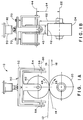
- FIG. 1A-3B an apparatus and method for rotary bonding are representatively illustrated in Figs. 1A-3B.
- the apparatus which is generally indicated at 10, and method may be used to bond at least two continuously moving substrate webs 12 and 14 together.
- the substrate webs 12 and 14 are continuously moving along a substrate path 16 in the direction indicated by the arrow 18 associated therewith.
- the apparatus 10 includes a rotatable bonding roll 20 which is located adjacent the substrate webs 12 and 14.
- the bonding roll 20 is configured to rotate about a bonding axis 22 in the direction indicated by the arrow 26 associated therewith.
- the bonding roll 20 has an outer peripheral bonding surface 24 upon which the substrate webs 12 and 14 travel.
- a rotatable anvil roll 40 having an outer peripheral anvil surface 42 and an anvil width 43 is located adjacent the bonding roll 20.
- the anvil roll 40 is configured to rotate about an anvil axis 44 in the direction indicated by the arrow 48 associated therewith to press the substrate webs 12 and 14 against the bonding surface 24 of the bonding roll 20 thereby bonding the substrate webs together.
- the anvil roll 40 is rotatably connected to a pivotal support means 50.
- the pivotal support means 50 continuously aligns the anvil axis to maintain the anvil surface 42 in a substantially parallel relationship with the bonding surface 24.
- the pivotal support means 50 is configured to allow the anvil roll 40 to pivot such that the anvil roll 40 continuously maintains a substantially constant force on the outer peripheral bonding surface 24 of the bonding roll 20 across the anvil width 43 of the anvil roll 40.
- the substrate webs 12 and 14 may be provided by any materials known to those skilled in the art which are compatible with the described bonding mechanisms.
- the substrate webs 12 and 14 may include a nonwoven material such as a spunbond, meltblown, spun laced or carded polymeric material, a film material such as a polyolefin or polyurethane film, a foam material or combinations thereof.
- nonwoven web shall mean a web of material which is formed without the aid of a textile weaving or knitting process.
- the substrate webs 12 and 14 may also be elastic or nonelastic such as films or layers of natural rubber, synthetic rubber or thermoplastic elastomeric polymers.
- the terms “elastomeric” or “elastic” refer to any material that, upon application of a biasing force, is capable of being elongated or stretched in a specified direction from at least about 20 percent to about 400 percent and which will recover to within at least from about 5 to about 35 percent of its original length after being elongated or stretched.
- the substrate webs 12 and 14 may be the same material or may be different materials.
- at least one of the substrate webs is formed from an elastomeric material such as a stretch-bonded-laminate (SBL) material, a neck-bonded-laminate (NBL) material, an elastomeric film, an elastomeric foam material, or the like as are well known to those skilled in the art.
- the bond can result from the partial or complete melting of the substrate webs 12 and 14.
- the bond can also result from the partial or complete melting of only one of the substrate webs 12 and 14 with the melted material flowing onto the adjacent substrate web which in turn results in the mechanical interlocking of the substrate webs to each other.
- the substrate webs 12 and 14 may be melted and bonded by any means known to those skilled in the art, such as, for example, thermally or ultrasonically.
- the substrate webs 12 and 14 may be adhesively bonded together by applying an adhesive to at least one of the substrate webs before the webs are pressed together using the apparatus and method of the present invention.
- the bonding roll 20 is configured to rotate about the bonding axis 22 in the direction indicated by the arrow 26 associated therewith.
- the bonding roll 20 can be connected to a shaft by suitable means such as by using welds, bolts, screws, a matching key and keyway and the like.
- the other rotating components of the apparatus 10 may also be connected using similar means.
- the bonding roll 20 and shaft may then be rotatably mounted and connected to a frame support by suitable means such as, for example, conventional bearings.
- the bonding roll 20 is driven by any means known to those skilled in the art such as, for example, an electric motor.
- the bonding roll 20 can be made from any material that is capable of withstanding the force exerted by the anvil roll 40.
- the bonding roll is made from steel.
- the bonding roll 20 can be heated and configured to thermally bond the substrate webs 12 and 14 together.
- the bonding roll 20 can include an ultrasonic bonding means 30 which can include a rotary ultrasonic horn 32.
- the anvil roll 40 is configured to rotate about the anvil axis 44 in the direction indicated by the arrow 48 associated therewith to press the substrate webs 12 and 14 against the bonding surface 24 of the rotary ultrasonic horn 32 thereby bonding the substrate webs together.
- the pivotal support means 50 is configured to allow the anvil roll 40 to pivot to continuously align the anvil axis 44 to maintain the anvil surface 42 in a substantially parallel relationship with the bonding surface 24 of the rotary ultrasonic horn 32.
- the anvil roll 40 can include the ultrasonic bonding means 30 and rotary ultrasonic horn 32.
- the rotary ultrasonic horn would press the substrate webs 12 and 14 against the bonding surface 24 of the bonding roll 20.
- the pivotal support means 50 would be configured to allow the rotary ultrasonic horn to pivot to continuously align the anvil axis 44 to maintain the anvil surface 42, or surface of the rotary ultrasonic horn, in a substantially parallel relationship with the bonding surface 24 of the bonding roll 20.
- the rotary ultrasonic horn 32 of the different aspects of the present invention includes a shaped, solid metal object.
- Representative examples of rotary ultrasonic horns which can be used in the present invention are described in commonly assigned U.S. Patent 5,096,532 to Neuwirth et al. and U.S. Patent 5,110,403 to Ehlert, which are herein incorporated by reference.
- the rotary ultrasonic horn 32 may be made from any metal having suitable acoustical and mechanical properties. Suitable metals include aluminum, monel, titanium and some alloy steels.
- variables such as the diameter, mass, width, thickness and configuration of the rotary ultrasonic horn 32 are not critical. However, the variables do determine the particular frequency and amplitude at which the rotary ultrasonic horn 32 resonates and vibrates.
- the rotary ultrasonic horn 32 is intended to be excited at a frequency of from about 18 to about 60 kHz.
- the horn 32 has a diameter of from about 4 to about 20 centimeters and a width at the bonding surface 24 of from about .6 to about 13 centimeters.
- the thickness of the horn at the rotational axis is from about .06 to about 15 centimeters.
- the horn has a mass in the range of from about 0.06 to about 30 kilograms.
- the diameter, width and thickness of the horn are selected such that the horn, upon being excited by ultrasonic energy at a desired frequency, is adapted to resonate such that the excited end moves substantially in phase with the movement of the source of excitation and the opposed end and bonding surface 24 move substantially out of phase with the excited end.
- the excited end moves in a direction towards the interior of the horn while the opposing end and the bonding surface 24 move in the opposite direction which is also towards the interior of the horn.
- the movements of the ends of the horn relative to each other are said to be out of phase.
- the ultrasonic bonding means 30 also includes a drive mechanism 80 to rotate and ultrasonically excite the rotary ultrasonic horn 32. Any mechanism which provides the desired rotation and excitation can be used in the present invention. Such mechanisms are well known to those skilled in the art.
- the ultrasonic bonding means 30 may include a drive mechanism 80 which is commercially available from Dukane Corporation located in St. Charles, Illinois or a similar system available from Branson Sonic Power Company located in Danbury, Connecticut.
- a generator such as a Dukane 1800 watt, 20 kHz generator (Part No. 20A1800)
- a driver assembly such as a Dukane driver assembly (Part No. 110-3123), to provide the necessary ultrasonic excitation.
- boosters such as a Dukane 1:1 booster (Part No. 2177T) and a Dukane 2:1 booster (Part No. 2181T) may then be attached to the driver assembly.
- the rotary ultrasonic horn 32 of the present invention is attached to the boosters.
- the combination of the generator, drive assembly and boosters ultrasonically excites the rotary ultrasonic horn 32 thereby providing the ultrasonic energy necessary to bond the substrate webs 12 and 14 together.
- the anvil roll 40 is configured to rotate about the anvil axis 44 and press the substrate webs 12 and 14 against the bonding surface 24 of the bonding roll 20, thereby bonding the substrate webs together.
- the anvil roll 40 is connected to a shaft which is rotatably mounted and connected to the pivotal support means 50 by any suitable means, such as conventional bearings.
- the anvil roll 40 may be made from any metal having suitable mechanical properties. Suitable metals include alloy steels.
- the anvil roll has an anvil surface 42 and an anvil width 43 of from about 1 to about 15 centimeters and desirably from about 3 to about 15 centimeters.
- the anvil surface 42 is configured to bond the substrate webs 12 and 14 together at bond locations which are arranged in a predetermined bond pattern. Applicants have found that as the width of the desired bond pattern and the corresponding anvil width 43 of the anvil roll 40 increases it becomes increasingly difficult to maintain the appropriate alignment between the anvil surface 42 and the bonding surface 24 when using a conventional anvil roll which is rigidly mounted.
- the anvil surface 42 of the anvil roll 40 may have a plurality of projections 46 thereon.
- the projections 46 may extend completely across the anvil surface 42 of the anvil roll 40 or, in the alternative, may be disposed on only a portion of the anvil surface 42.
- the projections 46 of the anvil roll 40 press the substrate webs 12 and 14 against the bonding roll 20 to bond the substrate webs 12 and 14 together at bond locations.
- the projections 46 of the anvil roll 40 can be configured such that the substrate webs 12 and 14 are bonded together at bond locations which are arranged in a predetermined bond pattern.
- the projections 46 may be of any shape or size depending upon the desired bonding configuration.
- the bonding surface 24 of the bonding roll 20 may also have a plurality of projections 46 thereon. The different aspects of the present invention are particularly useful when the width 47 of the bond pattern is at least about 1 centimeter, desirably from about 1 to about 13 centimeters and more desirably from about 2.5 to about 13 centimeters.
- the anvil roll 40 is rotatably mounted and connected to a pivotal support means 50 by any suitable means, such as conventional bearings.
- the pivotal support means 50 is configured to align the anvil axis 44 to maintain the anvil surface 42 in a substantially parallel relationship with the bonding surface 24.
- the pivotal support means 50 is configured to allow the anvil roll 40 to pivot such that the anvil roll is capable of self-aligning to continuously maintain a substantially constant force on the outer peripheral bonding surface 24 of the bonding roll 20. The force can be maintained substantially constant across the anvil width 43 of the anvil roll 40.
- the anvil roll 40 has a plurality of projections 46 thereon, the anvil roll is configured to maintain a substantially constant force on the outer peripheral bonding surface 24 of the bonding roll 20 at least substantially across the width of the projections 46 on the anvil roll 40.
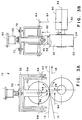
- the pivotal support means 50 may include an anvil support frame 54 which is pivotally connected to a rigid frame 52 at two pivot points 56 and 58 which are located on a pivot axis 60.
- the anvil roll 40 is connected to a shaft which is located on the anvil axis 44 and rotatably mounted and connected to the anvil support frame 54.
- the pivot axis 60 is perpendicular to both the anvil axis 44 and the bonding axis 22 and substantially parallel to the direction the substrate webs are moving along the substrate path 16 at any particular location.
- the anvil support frame 54 includes a pivot shaft which is rotatably mounted and connected to the rigid frame 52 at the pivot points 56 and 58.
- the pivot shaft is connected to the rigid frame 52 using a pair of conventional bearings such that the anvil support frame 54 and anvil roll 40 pivot about the pivot axis 60.
- the anvil roll 40 is capable of pivoting about the pivot axis 60 such that the anvil surface 42 is maintained in a substantially parallel relationship with the bonding surface 24.
- the anvil roll 40 is configured to self-align to maintain a substantially constant force on the outer peripheral bonding surface 24 of the bonding roll 20 substantially across the entire anvil width 43 of the anvil roll 40.
- the rigid frame 52 and anvil support frame 54 may have any shape or configuration which provides the desired pivoting of the anvil roll 40.
- the frames 52 and 54 may be made from any material capable of withstanding the forces exerted between the bonding roll 20 and anvil roll 40 during bonding.
- a suitable material is steel.
- the rigid frame 52 and anvil support frame 54 may both be u-shaped with the anvil roll 40 positioned in the interior portion of each frame 52 and 54.
- the conventional bearings can be mounted directly to the frames 52 and 54.
- the pivot axis 60 of the anvil support frame 54 is located a first distance 62 from the bonding axis 22 and the anvil axis 44 is located a second distance 64 from the bonding axis 22.
- the second distance 64 is dependent upon the particular diameters of the bonding roll 20 and anvil roll 40.
- the first distance 62 is less than the second distance 64 such that the pivot axis 60 is closer than the anvil axis 44 to the bonding axis 22.
- the first distance 62 may be at least about 1 percent, desirably from about 1 to about 50 percent and, more desirably from about 5 to about 25 percent less than the second distance 64. In such a configuration, Applicants have found that the bonding roll 20 and anvil roll 40 are more stable during use thereby providing improved bonding between the substrate webs 12 and 14.
- the pivotal support means 50 of the apparatus and method of the present invention may also include at least one pivot stop 70 to control an amount of pivot 72 of the anvil support frame 54 and the anvil roll 40.
- the pivot stops 70 limit the amount of pivot 72 of the anvil roll 40 to from 0 to about 15 degrees.
- the apparatus 10 and method of the present invention as representatively illustrated in Figs. 1A-3B, may also include a pressuring means 90 connected to the anvil roll 40 for exerting resilient force on the substrate webs 12 and 14 and the bonding roll 20 to bond the substrate webs 12 and 14 together.
- the pressuring means 90 should be capable of exerting a force of from about 1 to about 300 and desirably from about 0.1 to about 55 and desirably from about 2 to about 27 kilograms per lineal centimeter (from about 10 to about 150 pounds per lineal inch) on the bonding roll 20.
- Any mechanism capable of exerting the desired amount of force on the webs and bonding roll is suitable.
- an air cylinder 92 may be connected to the rigid frame 52.
- the air cylinder 92 may be configured to exert an actuating force on the rigid frame 52 which, in turn, transfers the force to the anvil support frame 54 through the pivot points 56 and 58.
- the rigid frame 52 is controlled by suitable restricting or constraining means known to those skilled in the art such that the rigid frame 52 is only capable of moving in the direction of the actuating force. Since the anvil roll 40 is connected to the anvil support frame 54, the force is transmitted to the anvil roll 40 to press the substrate webs 12 and 14 against the outer peripheral bonding surface 24 of the bonding roll 20.
- the bonding axis 22 can also be offset by a distance 94 from the anvil axis 44 such that the bonding axis 22 is not in a linear relationship with a line of force extending from the actuating force through the anvil axis 44. Applicants have found that such an arrangement is more stable than when the line of force extends directly through the bonding axis 22. Desirably, the bonding axis 22 is offset from the line of force by a distance 94 of from about 0.1 to about 7 centimeters and more desirably from about 0.5 to about 5 centimeters.
- the angle 96 as representatively illustrated in Fig. 3A, between the line of force and the anvil axis 44 and bonding axis 22 should be from about 0.3 to about 45 degrees and desirably from about 5 to about 30 degrees.
- the different aspects of the present invention advantageously provide an apparatus and method for rotary bonding.
- the present invention includes an anvil roll which is capable of self-aligning or pivoting such that its surface remains substantially parallel to the bonding surface.
- the anvil roll is capable of maintaining a substantially constant force on the bonding surface 24 of the bonding roll 20 across the entire anvil width 43 of the anvil roll 40.
- the anvil roll 40 may maintain an average force on the bonding surface 24 of the bonding roll 20 of from about 1 to about 300 pounds per lineal inch (from about 0.1 to about 55 kilograms per lineal centimeter) across the anvil width 43 of the anvil roll 40.
- the term "average” refers to the sum of the tested quantities divided by the total number of tested quantities.
- the different aspects of the present invention can provide a substantially constant bond area percentage between the webs.
- bond area percentage refers to the percentage of the total area of the two continuously moving webs which is bonded together. For example, as representatively illustrated in Fig. 2C, the bond area percentage would be calculated by determining the area of the substrate webs 12 and 14 which is actually bonded together, dividing the bonded area by the total area of the substrate webs and then multiplying the result by 100.
- the substrate webs produced using the anvil roll of the different aspects of the present invention have a bond area which is substantially the same as the area of the bond pattern on the anvil roll. Moreover, the webs have a substantially constant mean bond area percentage which has a standard deviation of from about 0 to about 5 and desirably from about 0 to about 1. The webs also have a bond area percentage which has a coefficient of variability of less than 10, and desirably less than 5.
- the term "mean” refers to the sum of the tested quantities divided by the total number of tested quantities.
- standard deviation refers to the square root of the average of the squares of the deviations of the tested quantities from the average of the tested quantities.
- coefficient of variability refers to the standard deviation of the mean bond area percentage divided by the mean bond area percentage. Substrate webs produced using the conventional, rigidly mounted anvils have had a much more variable bond area percentage.
- the mean bond area percentage of substrate webs bonded together using the anvil roll of the different aspects of the present invention is substantially greater than the mean bond area percentage of substrate webs bonded together using rigidly mounted anvils under similar operating conditions.
- the mean bond area percentage of substrate webs bonded together using the anvil roll of the different aspects of the present invention is at least about 105 percent and desirably from about 110 to about 300 percent of the mean bond area percentage of substrate webs bonded together using rigidly mounted anvils under similar operating conditions.
- substrate webs bonded together using the anvil roll of the different aspects of the present invention have a coefficient of variability which is substantially less than the coefficient of variability of substrate webs bonded together using rigidly mounted anvils.
- the substrate webs bonded together using the anvil roll of the different aspects of the present invention have a coefficient of variability which is at least less than 75 percent and desirably less than 50 percent of the coefficient of variability of substrate webs bonded together using rigidly mounted anvils under similar operating conditions.
- the different aspects of the invention can more efficiently provide an apparatus and method for bonding at least two continuously moving substrate webs together.
- the different aspects of the present invention provides more consistent bonds than conventional methods which use rigid anvil rolls because the anvil roll 40 is allowed to self-align or pivot to maintain contact with the bonding roll and to maintain a substantially constant force across the anvil width 43 of the anvil roll 40.
- the different aspects of the present invention may be used in the manufacture of an absorbent article, such as a disposable diaper which is representatively illustrated in Fig. 4.
- the absorbent article 200 defines a front portion 202, a rear portion 204, and a crotch portion 206 connecting the front portion 202 and the rear portion 204.
- the absorbent article 200 includes a bodyside liner 210, an outer cover 212, and an absorbent core 214 located between the bodyside liner 210 and the outer cover 212.
- reference to a front portion refers to that part of the absorbent article which is generally located on the front of a wearer when in use.
- Reference to the rear portion refers to the portion of the article generally located at the rear of the wearer when in use
- reference to the crotch portion refers to that portion which is generally located between the legs of the wearer when in use.
- the crotch portion 206 has opposite longitudinal side portions 208 which include a pair of elasticized, longitudinally extending leg cuffs 216.
- the leg cuffs 216 are generally adapted to fit about the legs of a wearer when in use and serve as a mechanical barrier to the lateral flow of body exudates.
- the leg cuffs 216 are elasticized by a pair of leg elastics 218.
- the absorbent article 200 further includes a front waist elastic 220 and a rear waist elastic 222.
- the rear portion 204 of the absorbent article 200 may further include a pair of stretchable ears 224 attached thereto which are adapted, in use, to overlap with the front portion 202 of the absorbent article 200.
- a fastening means such as snap closures, hook and loop fasteners, mushroom fasteners or tape fasteners may be attached to the stretchable ears 224 for releasably attaching the ears 224 to the front portion 202 of the absorbent article 200.
- the fastening means is intended to hold the absorbent article 200 about the waist of the wearer when in use.
- a hook material 226 may be attached to the stretchable ears 224 and a mating loop material 228 may be attached to the front portion 202 of the absorbent article 200.
- the stretchable ears 224 are attached to the back portion 204 of the absorbent article 200 using the various aspects of the method and apparatus of the present invention.
- the proximate edge 230 of the stretchable ears 224 may be ultrasonically bonded to the absorbent article 200 along the lateral edges 232 of the back portion 204 of the absorbent article using the apparatus and method representatively illustrated in Figs. 3A and 3B.
- the proximal edges 230 may be sandwiched between the outer cover 212 and bodyside liner 210 of the absorbent article 200 and ultrasonically bonded together.
- the materials used for the outer cover 212, bodyside liner 210 and stretchable ears 224 must be compatible with ultrasonic bonding techniques.
- the apparatus and method of the different aspects of the present invention may also be used to attach the fastening means to the absorbent article 200.
- the apparatus and method as representatively illustrated in Figs. 3A and 3B may be used to attach the hook material 226 to the stretchable ears 224.
- the bodyside liner 210 of the absorbent article 200 suitably presents a body-facing surface which is compliant, soft feeling, and non-irritating to the wearer's skin.
- the bodyside liner 210 may be less hydrophilic than the absorbent core 214, to present a relatively dry surface to the wearer, and may be sufficiently porous to be liquid permeable, permitting liquid to readily penetrate through its thickness.
- a suitable bodyside liner 210 may be manufactured from a wide selection of web materials such as porous foams, reticulated foams, apertured plastic films, natural fibers (for example, wood or cotton fibers), synthetic fibers (for example, polyester or polypropylene fibers), or a combination of natural and synthetic fibers.
- the bodyside liner 210 is suitably employed to help isolate the wearer's skin from liquids held in the absorbent core 214.
- the bodyside liner 210 may be composed of a meltblown or spunbonded web of polyolefin fibers.
- the bodyside liner 210 may also be a bonded carded web composed of natural and/or synthetic fibers.
- the bodyside liner 210 may be composed of a substantially hydrophobic material, and the hydrophobic material may, optionally, be treated with a surfactant or otherwise processed to impart a desired level of wettability and hydrophilicity.
- the bodyside liner 210 comprises a nonwoven, spunbond, polypropylene fabric composed of about 2.8-3.2 denier fibers formed into a web having a basis weight of about 22 grams per square meter and a density of about 0.06 grams per cubic centimeter.
- the fabric is surface treated with about .28 weight percent of a surfactant commercially available from Rohm and Haas Company under the trade designation Triton X-102.
- the outer cover 212 of the absorbent article 200 may suitably be composed of a material which is either liquid permeable or liquid impermeable. It is generally preferred that the outer cover 212 be formed from a material which is substantially impermeable to liquids.
- a typical outer cover can be manufactured from a thin plastic film or other flexible liquid impermeable material.
- the outer cover 212 may be formed from a polyethylene film having a thickness of from about 0.012 millimeter (0.5 mil) to about 0.051 millimeter (2.0 mils).
- the outer cover 212 may comprise a polyethylene film having a nonwoven web laminated to the outer surface thereof, such as a spunbond web of polyolefin fibers.
- a polyethylene film having a thickness of about 0.015 millimeter (0.6 mil) may have thermally laminated thereto a spunbond web of polyolefin fibers, which fibers have a thickness of about 1.5 to 2.5 denier per filament, which nonwoven web has a basis weight of about 24 grams per square meter (0.7 ounces per square yard).
- the outer cover 212 may be formed of a woven or nonwoven fibrous web layer which has been totally or partially constructed or treated to impart a desired level of liquid impermeability to selected regions that are adjacent or proximate the absorbent core 214. Still further, the outer cover 212 may optionally be composed of a microporous "breathable" material which permits vapors to escape from the absorbent core 214 while still preventing liquid exudates from passing into the outer cover 212.
- the absorbent core 214 of the absorbent article 200 is adapted to absorb body exudates. Any material capable of performing such a function is believed suitable for use in the present invention.
- the absorbent core 214 may comprise a single, integral piece of material or, alternatively, may comprise a plurality of individual, separate pieces of material which are operably assembled together.
- the absorbent core 214 may be manufactured in a wide variety of shapes and sizes (for example, rectangular, trapezoidal, T-shaped, I-shaped, hourglass shaped, etc.), and from a wide variety of materials.
- the size and the absorbent capacity of the absorbent core 214 should be compatible with the size of the intended wearer and the liquid loading imparted by the intended use of the absorbent article 200.
- the size and the absorbent capacity of the absorbent core 214 can be varied to accommodate wearers ranging from infants through adults. It is generally preferred that the absorbent core 214 be narrower in the crotch portion 206 of the absorbent article 200 than in the front or rear portion, 202 or 204, respectively.
- Suitable fibers include naturally occurring organic fibers composed of intrinsically wettable material, such as cellulosic fibers; synthetic fibers composed of cellulose or cellulose derivatives, such as rayon fibers; inorganic fibers composed of inherently wettable material, such as glass fibers; synthetic fibers made from inherently wettable thermoplastic polymers, such as particular polyester or polyamide fibers; and synthetic fibers composed of nonwettable thermoplastic polymer, such as polypropylene fibers, which have been hydrophilized by appropriate means.
- intrinsically wettable material such as cellulosic fibers
- synthetic fibers composed of cellulose or cellulose derivatives such as rayon fibers
- inorganic fibers composed of inherently wettable material such as glass fibers
- synthetic fibers made from inherently wettable thermoplastic polymers such as particular polyester or polyamide fibers
- synthetic fibers composed of nonwettable thermoplastic polymer such as polypropylene fibers, which have been hydrophilized by appropriate means.
- the fibers may be hydrophilized, for example, by treatment with silica, treatment with a material which has a suitable hydrophilic moiety and is not readily removable from the fiber, or by sheathing the nonwettable, hydrophobic fiber with a hydrophilic polymer during or after the formation of the fiber.
- hydrophilic describes fibers or the surface of fibers, which are wetted by the aqueous liquids in contact with the fibers. The degree of wetting of the materials can, in turn, be described in terms of the contact angles and the surface tensions of the liquids and materials involved.
- Equipment and techniques suitable for measuring the wettability of particular fiber materials or blends of fiber materials can be provided by a Cahn SFA-222 surface force analyzer system. When measured with this system, fibers having contact angles less than 90 degrees are designated “wettable”, while fibers having contact angles greater than 90 degrees are designated “nonwettable”.
- the absorbent core 214 may suitably comprise a high-absorbency material such as those known in the art as "superabsorbents”.
- the high absorbency material is present in the absorbent core 214 in an amount of from about 5 to about 100 weight percent based on total weight of the absorbent core to provide more effective performance.
- High-absorbency materials can be natural, synthetic, and modified natural polymers and materials.
- the high-absorbency materials can be inorganic materials such as silica gels, or organic compounds such as crosslinked polymers.
- crosslinked refers to any means for effectively rendering normal water-soluble materials substantially water insoluble but swellable. Such means can include, for example, physical entanglement, crystalline domains, covalent bonds, ionic complexes and associations, hydrophilic associations such as hydrogen bonding, and hydrophobic associations or Van der Waals forces.
- synthetic high-absorbency materials include polymeric materials, such as alkali metal and ammonium salts of poly(acrylic acid) and poly(methacrylic acid), poly(acrylamides), poly(vinyl ethers), maleic anhydride copolymers with vinyl ethers and alpha-olefins, poly(vinyl pyrolidone), poly(vinyl morpholinone), poly(vinyl alcohol), and mixtures and copolymers thereof.
- polymeric materials such as alkali metal and ammonium salts of poly(acrylic acid) and poly(methacrylic acid), poly(acrylamides), poly(vinyl ethers), maleic anhydride copolymers with vinyl ethers and alpha-olefins, poly(vinyl pyrolidone), poly(vinyl morpholinone), poly(vinyl alcohol), and mixtures and copolymers thereof.
- Further polymers suitable for use in the absorbent core include natural and modified natural polymers, such as hydrolyzed acrylonitrile-grafted starch, acrylic acid grafted starch, methyl cellulose, carboxymethyl cellulose, hydroxypropyl cellulose, and the natural gums, such as alginates, xanthum gum, locust bean gum, and the like. Mixtures of natural and wholly or partially synthetic absorbent polymers can also be useful in the present invention.
- Other suitable absorbent gelling materials are disclosed by Assarson et al. in U.S. Patent No. 3,902,236 issued August 26, 1975. Processes for preparing synthetic, absorbent gelling polymers are disclosed in U.S. Patent No. 4,076,663 issued February 28, 1978, to Masuda et al. and U.S. Patent No. 4,286,082 issued August 25, 1981, to Tsubakimoto et al.
- the high-absorbency material may be in any of a wide variety of geometric forms. As a general rule, it is preferred that the high-absorbency material be in the form of discrete particles. However, the high-absorbency material may also be in the form of fibers, flakes, rods, spheres, needles, or the like.
- the outer cover 212 and bodyside liner 210 are generally adhered to one another so as to form a pocket in which the absorbent core 214 is located.
- the leg cuffs 216 are suitably formed by portions of the outer cover 212, and/or bodyside liner 210, which extend beyond the longitudinal sides of the absorbent core 214.
- the leg cuffs 216 can also be formed from separate materials which are attached to the outer cover 212 and/or bodyside liner 210.
- the leg cuffs 216 include leg elastics 218.
- Materials suitable for use in forming the leg elastics 218 are known to those skilled in the art.
- the leg elastics 218 may include a plurality of elastic strands, such as, for example, Lycra® elastomeric strands available from DuPont, a business having offices in Wilmington, Delaware.
- the elastic strands are typically within the range of 470-1500 decitex.
- the leg elastics 218 may be generally straight or optionally curved.
- the waist elastics 220 and 222 are well known to those skilled in the art.
- Patent 5,147,343 issued September 15, 1992, to Kellenberger; U.S. Patent Application Serial No. 07/997,800 filed December 29, 1992, in the name of McCormack et al., and U.S. Patent Application Serial No. 08/148,130 filed November 5, 1993, in the name of Dilnik et al.
- the apparatus 10 as representatively illustrated in Figs. 3A and 3B, was used to provide imprints on nip impression paper as the bond pattern and force between the anvil roll 40 and bonding roll 20 were varied.
- the imprints were used to provide a comparison of the bond quality and consistency obtained when using the self-aligning anvil roll 40 of the different aspects of the present invention versus a fixed anvil roll.
- Two anvil rolls 40 which have two different bond patterns were used.
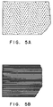
- the first anvil roll 40 had a diameter of 15.0 cm (5.89 inches) and had bond pattern A as representatively illustrated in Fig. 5A.
- the second anvil roll 40 had a diameter of 13.3 cm (5.25 inches) and had bond pattern B as representatively illustrated in Fig. 5B.
- Each anvil roll 40 had a width of 10.16 cm (4.0 inches) with the corresponding bond pattern extending completely across the width of the anvil roll.
- the actuating force exerted between the anvil roll 40 and the bonding roll 20 was controlled such that imprints were made with actuating forces of 275.79 kPa (40 psi (pounds per square inch)), 344.74 kPa (50 psi) and 413.69 kPa (60 psi).
- the force translates into a normalized force of 11.52 kg per lineal cm (10 pli (pounds per lineal inch)), 14.40 kg per lineal cm (12.5 pli) and 17.28 kg per lineal cm (15 pli), respectively, across the surface of each anvil roll 40.
- the first anvil roll 40 which had bond pattern A was used in conjunction with a rotary ultrasonic bonding roll 20 or horn to provide the imprint on the nip impression paper.
- the anvil roll 40 was fixed by adjusting the pivot stops 70 to maintain the anvil roll 40 in a desired position.
- the pressuring means 90 exerted a force of 275.79 kPa (40 psi) such that the anvil roll exerted a force of 11.52 kg per lineal cm (10 pli) between the bonding roll 20 and anvil roll 40.
- the rotary ultrasonic bonding roll 20 was rotated such that the impression paper was moved at about 5 meters per minute (about 17 feet per minute) between the bonding roll 20 and the fixed anvil roll 40.
- the contact between the anvil roll 40 and the bonding roll 20 caused an imprint to be made on the nip impression paper.
- the imprint was analyzed to determine the bond area percentage.
- the term "bond area percentage” refers to the percentage of the total area of the impression paper which was actually imprinted.
- the bond area percentage of the impression paper approximates the actual bond area percentage which would occur when bonding two substrate webs together.
- the bond area percentage was calculated by determining the area of the impression paper which was actually imprinted, dividing the imprinted area by the total area of the paper and then multiplying the result by 100.
- the impression paper was viewed through a 20MM Nikon lens from a height of 90 centimeters with 4 flood lamps directed at the impression paper.
- the bond area percentage of the impression paper was then determined using a Quantimet 970 Image Analyzer which is commercially available from Leica Instruments, Inc., a company having business offices located in Deerfield, Illinois.
- the image analyzer was equipped with version 8.0 software which is also available from Leica Instruments, Inc.
- a length of the imprint was divided into 40 equal frames of about .56 centimeters in width.
- the image analyzer determined the mean bond area percentage for each frame by differentiating between the darkened or imprinted areas and the lighter or nonimprinted areas.
- the mean bond area percentage and standard deviation for all of the frames was then determined.
- the imprint had a mean bond area percentage of 6.53 percent with a standard deviation of 0.84.
- the imprint also had a coefficient of variability of 12.9.
- the first anvil roll 40 which had bond pattern A was used again in conjunction with a rotary ultrasonic bonding roll 20 or horn to provide an imprint on the nip impression paper.
- the anvil roll 40 was fixed by adjusting the pivot stops 70 to maintain the anvil roll 40 in a desired position.
- the pressuring means 90 exerted a force of 344.74 kPa (50 psi) such that the anvil roll exerted a force of 14.40 kg per lineal cm (12.5 pli) between the bonding roll 20 and anvil roll 40.
- the rotary ultrasonic bonding roll 20 was rotated such that the impression paper was moved at about 5 meters per minute (about 17 feet per minute) between the bonding roll 20 and the fixed anvil roll 40. The contact between the anvil roll 40 and the bonding roll 20 caused an imprint to be made on the nip impression paper.
- the imprint was analyzed as described in Example 1 to determine the bond area percentage of each frame and the mean bond area percentage and standard deviation for all of the frames.
- the imprint had a mean bond area percentage of 8.27 percent with a standard deviation of 1.45.
- the imprint also had a coefficient of variability of 17.5.
- the first anvil roll 40 which had bond pattern A was used again in conjunction with a rotary ultrasonic bonding roll 20 or horn to provide an imprint on the nip impression paper.
- the anvil roll 40 was fixed by adjusting the pivot stops 70 to maintain the anvil roll 40 in a desired position.
- the pressuring means 90 exerted a force of 413.69 kPa (60 psi) such that the anvil roll exerted a force of 17.28 kg per lineal cm (15.0 pli) between the bonding roll 20 and anvil roll 40.
- the rotary ultrasonic bonding roll 20 was rotated such that the impression paper was moved at about 5 meters per minute (about 17 feet per minute) between the bonding roll 20 and the fixed anvil roll 40. The contact between the anvil roll 40 and the bonding roll 20 caused an imprint to be made on the nip impression paper.
- the imprint was analyzed as described in Example 1 to determine the bond area percentage of each frame and the mean bond area percentage and standard deviation for all of the frames.
- the imprint had a mean bond area percentage of 11.70 percent with a standard deviation of 3.32.
- the imprint also had a coefficient of variability of 28.4.
- the first anvil roll 40 which had bond pattern A was used again in conjunction with a rotary ultrasonic bonding roll 20 or horn to provide the imprint on the nip impression paper.
- the anvil roll 40 was allowed to self-align with the bonding roll 20 by adjusting the pivot stops 70 to allow the anvil roll 40 to pivot.
- the surface of the anvil roll 40 maintained a substantially parallel relationship with the surface of the bonding roll 20.
- the pressuring means 90 exerted a force of 275.79 kPa (40 psi) such that the anvil roll exerted a force of 11.52 kg per lineal cm (10 pli) between the bonding roll 20 and anvil roll 40.
- the rotary ultrasonic bonding roll 20 was rotated such that the impression paper was moved at about 5 meters per minute (about 17 feet per minute) between the bonding roll 20 and the fixed anvil roll 40.
- the contact between the anvil roll 40 and the bonding roll 20 caused an imprint to be made on the nip impression paper.
- the imprint was analyzed as described in Example 1 to determine the bond area percentage of each frame and the mean bond area percentage and standard deviation for all of the frames.
- the imprint had a mean bond area percentage of 15.70 percent with a standard deviation of 0.43.
- the imprint also had a coefficient of variability of 2.7.
- the first anvil roll 40 which had bond pattern A was used again in conjunction with a rotary ultrasonic bonding roll 20 or horn to provide an imprint on the nip impression paper.
- the anvil roll 40 was allowed to self-align with the bonding roll 20 by adjusting the pivot stops 70 to allow the anvil roll 40 to pivot.
- the surface of the anvil roll 40 maintained a substantially parallel relationship with the surface of the bonding roll 20.
- the pressuring means 90 exerted a force of 344.74 kPa (50 psi) such that the anvil roll exerted a force of 14.40 kg per lineal cm (12.5 pli) between the bonding roll 20 and anvil roll 40.
- the rotary ultrasonic bonding roll 20 was rotated such that the impression paper was moved at about 5 meters per minute (about 17 feet per minute) between the bonding roll 20 and the fixed anvil roll 40.
- the contact between the anvil roll 40 and the bonding roll 20 caused an imprint to be made on the nip impression paper.
- the imprint was analyzed as described in Example 1 to determine the bond area percentage of each frame and the mean bond area percentage and standard deviation for all of the frames.
- the imprint had a mean bond area percentage of 16.10 percent with a standard deviation of 0.62.
- the imprint also had a coefficient of variability of 3.9.
- the first anvil roll 40 which had bond pattern A was used again in conjunction with a rotary ultrasonic bonding roll 20 or horn to provide an imprint on the nip impression paper.
- the anvil roll 40 was allowed to self-align with the bonding roll 20 by adjusting the pivot stops 70 to allow the anvil roll 40 to pivot.
- the surface of the anvil roll 40 maintained a substantially parallel relationship with the surface of the bonding roll 20.
- the pressuring means 90 exerted a force of 413.69 kPa (60 psi) such that the anvil roll exerted a force of 17.28 kg per lineal cm (15 pli) between the bonding roll 20 and anvil roll 40.
- the rotary ultrasonic bonding roll 20 was rotated such that the impression paper was moved at about 5 meters per minute (about 17 feet per minute) between the bonding roll 20 and the fixed anvil roll 40.
- the contact between the anvil roll 40 and the bonding roll 20 caused an imprint to be made on the nip impression paper.
- the imprint was analyzed as described in Example 1 to determine the bond area percentage of each frame and the mean bond area percentage and standard deviation for all of the frames.
- the imprint had a mean bond area percentage of 17.80 percent with a standard deviation of 0.46.
- the imprint also had a coefficient of variability of 2.6.
- the second anvil roll 40 which had bond pattern B, as representatively illustrated in Fig. 5B, was used in conjunction with a rotary ultrasonic bonding roll 20 or horn to provide an imprint on the nip impression paper.
- the anvil roll 40 was fixed by adjusting the pivot stops 70 to maintain the anvil roll 40 in a desired position.
- the pressuring means 90 exerted a force of 275.79 kPa (40 psi) such that the anvil roll exerted a force of 11.52 kg per lineal cm (10.0 pli) between the bonding roll 20 and anvil roll 40.
- the rotary ultrasonic bonding roll 20 was rotated such that the impression paper was moved at about 5 meters per minute (about 17 feet per minute) between the bonding roll 20 and the fixed anvil roll 40.
- the contact between the anvil roll 40 and the bonding roll 20 caused an imprint to be made on the nip impression paper.
- the imprint was analyzed as described in Example 1 to determine the bond area percentage of each frame and the mean bond area percentage and standard deviation for all of the frames.
- the imprint had a mean bond area percentage of 21.5 percent with a standard deviation of 6.6.
- the imprint also had a coefficient of variability of 30.7.
- the second anvil roll 40 which had bond pattern B was used in conjunction with a rotary ultrasonic bonding roll 20 or horn to provide an imprint on the nip impression paper.
- the anvil roll 40 was fixed by adjusting the pivot stops 70 to maintain the anvil roll 40 in a desired position.
- the pressuring means 90 exerted a force of 344.74 kPa (50 psi) such that the anvil roll exerted a force of 14.40 kg per lineal cm (12.5 pli) between the bonding roll 20 and anvil roll 40.
- the rotary ultrasonic bonding roll 20 was rotated such that the impression paper was moved at about 5 meters per minute (about 17 feet per minute) between the bonding roll 20 and the fixed anvil roll 40. The contact between the anvil roll 40 and the bonding roll 20 caused an imprint to be made on the nip impression paper.
- the imprint was analyzed as described in Example 1 to determine the bond area percentage of each frame and the mean bond area percentage and standard deviation for all of the frames.
- the imprint had a mean bond area percentage of 25.0 percent with a standard deviation of 7.1.
- the imprint also had a coefficient of variability of 28.4.
- the second anvil roll 40 which had bond pattern B was used again in conjunction with a rotary ultrasonic bonding roll 20 or horn to provide an imprint on the nip impression paper.
- the anvil roll 40 was fixed by adjusting the pivot stops 70 to maintain the anvil roll 40 in a desired position.
- the pressuring means 90 exerted a force of 413.69 kPa (60 psi) such that the anvil roll exerted a force of 17.28 kg per lineal cm (15.0 pli) between the bonding roll 20 and anvil roll 40.
- the rotary ultrasonic bonding roll 20 was rotated such that the impression paper was moved at about 5 meters per minute (about 17 feet per minute) between the bonding roll 20 and the fixed anvil roll 40. The contact between the anvil roll 40 and the bonding roll 20 caused an imprint to be made on the nip impression paper.
- the imprint was analyzed as described in Example 1 to determine the bond area percentage of each frame and the mean bond area percentage and standard deviation for all of the frames.
- the imprint had a mean bond area percentage of 27.1 percent with a standard deviation of 3.2.
- the imprint also had a coefficient of variability of 11.8.
- the second anvil roll 40 which had bond pattern B was used again in conjunction with a rotary ultrasonic bonding roll 20 or horn to provide an imprint on the nip impression paper.
- the anvil roll 40 was allowed to self-align with the bonding roll 20 by adjusting the pivot stops 70 to allow the anvil roll 40 to pivot.
- the surface of the anvil roll 40 maintained a substantially parallel relationship with the surface of the bonding roll 20.
- the pressuring means 90 exerted a force of 275.79 kPa (40 psi) such that the anvil roll exerted a force of 11.52 kg per lineal cm (10.0 pli) between the bonding roll 20 and anvil roll 40.
- the rotary ultrasonic bonding roll 20 was rotated such that the impression paper was moved at about 5 meters per minute (about 17 feet per minute) between the bonding roll 20 and the fixed anvil roll 40.
- the contact between the anvil roll 40 and the bonding roll 20 caused an imprint to be made on the nip impression paper.
- the imprint was analyzed as described in Example 1 to determine the bond area percentage of each frame and the mean bond area percentage and standard deviation for all of the frames.
- the imprint had a mean bond area percentage of 34.0 percent with a standard deviation of 1.3.
- the imprint also had a coefficient of variability of 3.8.
- the second anvil roll 40 which had bond pattern B was used again in conjunction with a rotary ultrasonic bonding roll 20 or horn to provide an imprint on the nip impression paper.
- the anvil roll 40 was allowed to self-align with the bonding roll 20 by adjusting the pivot stops 70 to allow the anvil roll 40 to pivot.
- the surface of the anvil roll 40 maintained a substantially parallel relationship with the surface of the bonding roll 20.
- the pressuring means 90 exerted a force of 344.74 kPa (50 psi) such that the anvil roll exerted a force of 14.40 kg per lineal cm (12.5 pli) between the bonding roll 20 and anvil roll 40.
- the rotary ultrasonic bonding roll 20 was rotated such that the impression paper was moved at about 5 meters per minute (about 17 feet per minute) between the bonding roll 20 and the fixed anvil roll 40.
- the contact between the anvil roll 40 and the bonding roll 20 caused an imprint to be made on the nip impression paper.
- the imprint was analyzed as described in Example 1 to determine the bond area percentage of each frame and the mean bond area percentage and standard deviation for all of the frames.
- the imprint had a mean bond area percentage of 34.4 percent with a standard deviation of 1.3.
- the imprint also had a coefficient of variability of 3.8.
- the second anvil roll 40 which had bond pattern B was used again in conjunction with a rotary ultrasonic bonding roll 20 or horn to provide an imprint on the nip impression paper.
- the anvil roll 40 was allowed to self-align with the bonding roll 20 by adjusting the pivot stops 70 to allow the anvil roll 40 to pivot.
- the surface of the anvil roll 40 maintained a substantially parallel relationship with the surface of the bonding roll 20.
- the pressuring means 90 exerted a force of 413.69 kPa (60 psi) such that the anvil roll exerted a force of 17.28 kg per lineal cm (15.0 pli) between the bonding roll 20 and anvil roll 40.
- the rotary ultrasonic bonding roll 20 was rotated such that the impression paper was moved at about 5 meters per minute (about 17 feet per minute) between the bonding roll 20 and the fixed anvil roll 40.
- the contact between the anvil roll 40 and the bonding roll 20 caused an imprint to be made on the nip impression paper.
- the imprint was analyzed as described in Example 1 to determine the bond area percentage of each frame and the mean bond area percentage and standard deviation for all of the frames.
- the imprint had a mean bond area percentage of 35.4 percent with a standard deviation of 1.2.
- the imprint also had a coefficient of variability of 3.4.
- Fig. 6 representatively shows a graph which compares the bond area percentage achieved in Example 7 (Fixed anvil roll) with that achieved in Example 10 (Self-aligning anvil roll) along a specified length of the imprint.
- the imprints made using the self-aligning anvil roll of the different aspects of the present invention were more consistent and more accurately reflect the bond pattern used on the anvil roll than the imprints made using the fixed anvil roll.
- the imprints produced using the anvil roll of the different aspects of the present invention had a bond area percentage which was from 15.70 to 17.80 percent with a standard deviation of from 0.43 to 0.62.
- the imprints produced using the conventional, rigidly mounted or fixed anvil rolls had a bond area percentage which was from 6.53 to 11.70 percent with a standard deviation of from 0.84 to 3.32.
- the imprints produced using the anvil roll of the different aspects of the present invention had a bond area percentage which was from 34.0 to 35.4 percent with a standard deviation of from 1.2 to 1.3.
Abstract
Description
- The present invention relates to an apparatus and method for bonding at least two continuously moving webs together. The invention more particularly concerns an apparatus and method for ultrasonically bonding at least two continuously moving webs together using a rotary ultrasonic horn.
- Several different conventional methods have existed for bonding at least two continuously moving webs together. For example, it has been well known to those skilled in the art to bond two continuously moving substrate webs together by constrictively passing them between a rotating bonding roll and a rotating anvil roll. Typically, the anvil roll has been configured to bond the webs together in a predetermined bond pattern. The substrate webs have been bonded together by any means known to those skilled in the art such as thermal, ultrasonic or adhesive bonding. For example, the bonding roll has been heated to thermally bond the webs together as the webs constrictively travelled between the bonding roll and the anvil roll. Alternatively, the bonding roll has included a rotary ultrasonic horn which has been capable of transmitting ultrasonic energy to ultrasonically bond the two webs together as they constrictively travelled between the rotary ultrasonic horn and the anvil roll. Representative examples of rotary ultrasonic horns which have been used to bond at least two webs together are described in commonly assigned U.S. Patents 5,096,532 to Neuwirth et al. and 5,110,403 to Ehlert.
- The consistency and quality of the bonds between the webs when using rotary bonding techniques is dependent upon the force exerted on the webs by the anvil roll and bonding roll; the time that the webs are pressed together which is dependent upon the operating speed; and the types of materials being bonded together. In thermal bonding methods, the consistency and quality of the bonds has also been dependent on the temperature of the bonding roll. In ultrasonic bonding methods, the consistency and quality of the bonds has also been dependent on the frequency and amplitude of the vibrations of the ultrasonic horn.
- Many of the conventional methods for rotary bonding have included a rotating anvil which is rigidly mounted. However, such conventional methods have not been sufficiently satisfactory. Although the use of a rigidly mounted, rotating anvil was a significant improvement in continuous bonding methods, such use has some inherent limitations which adversely affect the bond quality which, in turn, limits the operating speeds. When the rotating anvil is rigidly mounted, the consistency and quality of the bonds between the two webs is dependent upon the runout in both the bonding roll and the anvil roll and the amount that both rolls flex when under a variable load due to the types of materials being bonded and the variable operating speeds. In such a configuration, it has been virtually impossible to maintain proper alignment between the bonding roll and the anvil roll to achieve the desired constant force between the rolls in the bond region especially as the process variables change. Thus, in many of the conventional methods for rotary bonding, the bond quality has been undesirably variable both along the length and across the width of the bond region.
- The consistency and quality of the bonds when rotary bonding using conventional methods has been particularly variable as the width of the desired bond pattern exceeds about 1 centimeter because it becomes increasingly difficult to maintain the constant force and contact between the bonding and anvil rolls across the entire width of the bond pattern. When using many of the conventional methods for rotary bonding in such a configuration, the actual percentage of the area of the webs being bonded together has been much less than the desired bond area based on the area of bond pattern on the anvil roll.
- Many of the conventional methods for rotary bonding have used different approaches to diminish the extent of these limitations. For example, the bonding roll, anvil roll and support frames have been precisely machined to minimize the runout in the bonding system. In addition, the strength of the bonding and anvil rolls and their support frames has been increased to minimize the flexing under the variable load conditions. However, these approaches have been expensive and inefficient and have required extensive setup modifications as the process variables, such as operating speed, are changed.
- The above-mentioned difficulties of maintaining the desired bond quality and consistency have been even more acute when ultrasonically bonding at least two continuously moving webs together using a rotary ultrasonic horn. The rotary ultrasonic horn has inherent movement which may adversely affect bond consistency and quality because it continuously vibrates at a given frequency and amplitude to efficiently bond the two webs together. Moreover, the rotary ultrasonic horn has usually been mounted in a cantilevered configuration which enhances the amount of flex under load.
- In response to the discussed difficulties and problems encountered in the prior art, it is the object of the present invention to provide a new apparatus and method for rotary bonding.
- This object is solved by the apparatus of
independent claim 1, the apparatus ofindependent claim 4 and the method ofindependent claim 10. Further advantageous features, aspects and details of the invention are evident from the dependent claims, the description and the drawings. The claims are to be understood as a first non-limiting approach of defining the invention in general terms. - According to one aspect, the present invention provides a distinctive apparatus for bonding at least two continuously moving substrate webs together. The apparatus comprises a rotatable bonding roll which is located adjacent the substrate webs and configured to rotate about a bonding axis. The bonding roll has an outer peripheral bonding surface upon which the substrate webs travel. A rotatable anvil roll having an outer peripheral anvil surface is located adjacent the bonding roll. The anvil roll is configured to rotate about an anvil axis to press the substrate webs against the bonding surface of the bonding roll thereby bonding the substrate webs together. The anvil roll is rotatably connected to a pivotal support means. The pivotal support means is configured to continuously align the anvil axis to maintain the anvil surface in a substantially parallel relationship with the bonding surface. The pivotal support means is configured to allow the anvil roll to pivot such that the anvil roll continuously maintains a substantially constant force on the outer peripheral bonding surface of the bonding roll across the width of the anvil roll.
- According to another aspect, the present invention provides an apparatus for ultrasonically bonding at least two continuously moving substrate webs together. The apparatus comprises an ultrasonic bonding means which provides ultrasonic energy. The ultrasonic bonding means includes a rotary ultrasonic horn which is configured to rotate about a bonding axis. The rotary ultrasonic horn has an outer peripheral bonding surface upon which the substrate webs travel. An anvil support frame is pivotally connected to a rigid frame at two pivot points located on a pivot axis. A rotatable anvil roll having an anvil surface is rotatably connected to the anvil support frame. The anvil roll is configured to rotate about an anvil axis and press the webs against the bonding surface of the rotary ultrasonic horn thereby bonding the substrate webs together. The anvil support frame is configured to pivot about the pivot axis to maintain the anvil surface in a substantially parallel relationship with the bonding surface of the rotary ultrasonic horn. In a particular aspect, the rotatable anvil roll has a plurality of projections across the anvil surface which are configured to bond the substrate webs together at bond locations which are arranged in a predetermined bond pattern. The bond pattern may have a width of at least about 1 centimeter.
- A further aspect of the present invention provides a method for bonding at least two continuously moving substrate webs together. At least two continuously moving substrate webs are supplied along a substrate path. A rotatable bonding roll is provided adjacent the substrate path. The bonding roll is rotated about a bonding axis and has an outer peripheral bonding surface upon which the substrate webs travel. A rotatable anvil roll which has an outer peripheral anvil surface and an anvil width is also provided adjacent the substrate path. The anvil roll rotates about an anvil axis and presses the substrate webs against the bonding surface of the bonding roll thereby bonding the substrate webs together across the outer peripheral anvil surface of the anvil roll. The anvil roll is pivotally supported to continuously align the anvil axis to maintain the anvil surface in a substantially parallel relationship with the bonding surface. The anvil roll can maintain a substantially constant force on the outer peripheral bonding surface of the bonding roll across the width of the anvil roll. In a particular aspect of the method of the present invention, the bonding roll may comprise an ultrasonic bonding means which includes a rotary ultrasonic horn.
- The present invention can advantageously provide an apparatus and method for rotary bonding which, when compared to conventional devices, can more efficiently bond two continuously moving webs together while maintaining a substantially constant bond pattern between the webs. The apparatus and method of the present invention automatically adjust the alignment between the bonding roll and the anvil roll to compensate for runout and the flex due to the variable loads thereby improving the bond quality and consistency. The apparatus of the present invention is also less expensive when compared to the conventional devices because lower precision components can be employed.
- The present invention will be more fully understood and further advantages will become apparent when reference is made to the following detailed description of the invention and the accompanying drawings. The drawings are merely representative and are not intended to limit the scope of the appended claims.
- Fig. 1A representatively shows a front elevational view of one example of an apparatus of the present invention;
- Fig. 1B representatively shows a side elevational view of the apparatus illustrated in Fig. 1A;
- Fig. 2A representatively shows an example of an anvil roll of the apparatus of the present invention;
- Fig. 2B representatively shows another example of an anvil roll of the apparatus of the present invention;
- Fig. 2C representatively shows an example of a composite substrate web which is manufactured using the apparatus and method of the present invention;
- Fig. 3A representatively shows a front elevational view of another example of an apparatus of the present invention;
- Fig. 3B representatively shows a side elevational view of the apparatus illustrated in Fig. 3A;
- Fig. 4 representatively shows an absorbent article which is manufactured using the apparatus and method of the present invention;
- Fig. 5A representatively shows an example of a bond pattern which may be used on the anvil roll of the different aspects of the present invention;
- Fig. 5B representatively shows an example of another bond pattern which may be used on the anvil roll of the different aspects of the present invention; and
- Fig. 6 representatively shows a graph comparing the different bond area percentages achieved using a fixed or rigid anvil roll versus the anvil roll of the different aspects of the present invention.
- The present invention provides an apparatus and method for bonding at least two continuously moving substrate webs together. The apparatus and method are particularly useful for ultrasonically bonding selected components to absorbent articles using a rotary ultrasonic horn. Alternatively, the apparatus and method are useful for bonding two webs together to form a composite material and subsequently using it as a component in an absorbent article such as, for example, a disposable diaper. The present invention is particularly useful in the bonding of two or more layers of materials which preferably are made, at least in part, from thermoplastic polymers.
- In particular, the apparatus and method of the present invention can be used to ultrasonically bond stretchable outer ears to a disposable diaper using a rotary ultrasonic horn. The stretchable outer ears enhance the fit of the diaper about the waist of the wearer. The apparatus and method of the present invention may also be used to bond a fastening system to the outer ears of the diaper. In addition, it should be readily understood that the apparatus and method of the present invention may be used in the manufacture of other types of articles, such as, for example, training pants, feminine care products, incontinence garments, hospital gowns and the like. All of such alternative configurations are contemplated as being within the scope of the present invention. The present invention may also be used to perforate a material such as, for example, using a rotary ultrasonic horn to selectively perforate a material.
- Referring to the Figures wherein like numerals represent like elements, an apparatus and method for rotary bonding are representatively illustrated in Figs. 1A-3B. The apparatus, which is generally indicated at 10, and method may be used to bond at least two continuously moving
substrate webs substrate webs substrate path 16 in the direction indicated by thearrow 18 associated therewith. Theapparatus 10 includes arotatable bonding roll 20 which is located adjacent thesubstrate webs bonding roll 20 is configured to rotate about abonding axis 22 in the direction indicated by thearrow 26 associated therewith. Thebonding roll 20 has an outerperipheral bonding surface 24 upon which thesubstrate webs rotatable anvil roll 40 having an outerperipheral anvil surface 42 and ananvil width 43 is located adjacent thebonding roll 20. Theanvil roll 40 is configured to rotate about ananvil axis 44 in the direction indicated by thearrow 48 associated therewith to press thesubstrate webs bonding surface 24 of thebonding roll 20 thereby bonding the substrate webs together. Theanvil roll 40 is rotatably connected to a pivotal support means 50. The pivotal support means 50 continuously aligns the anvil axis to maintain theanvil surface 42 in a substantially parallel relationship with thebonding surface 24. The pivotal support means 50 is configured to allow theanvil roll 40 to pivot such that theanvil roll 40 continuously maintains a substantially constant force on the outerperipheral bonding surface 24 of thebonding roll 20 across theanvil width 43 of theanvil roll 40. - The
substrate webs substrate webs substrate webs substrate webs - It should be apparent that adequate bonding can be achieved by a variety of mechanisms. For example, the bond can result from the partial or complete melting of the
substrate webs substrate webs substrate webs substrate webs - As representatively illustrated in Figs. 1A-3B, the
bonding roll 20 is configured to rotate about thebonding axis 22 in the direction indicated by thearrow 26 associated therewith. Thebonding roll 20 can be connected to a shaft by suitable means such as by using welds, bolts, screws, a matching key and keyway and the like. The other rotating components of theapparatus 10 may also be connected using similar means. Thebonding roll 20 and shaft may then be rotatably mounted and connected to a frame support by suitable means such as, for example, conventional bearings. Typically, thebonding roll 20 is driven by any means known to those skilled in the art such as, for example, an electric motor. Thebonding roll 20 can be made from any material that is capable of withstanding the force exerted by theanvil roll 40. - Desirably, the bonding roll is made from steel. In one aspect, the
bonding roll 20 can be heated and configured to thermally bond thesubstrate webs - In another aspect of the invention, the continuously moving
substrate webs bonding roll 20 can include an ultrasonic bonding means 30 which can include a rotaryultrasonic horn 32. Theanvil roll 40 is configured to rotate about theanvil axis 44 in the direction indicated by thearrow 48 associated therewith to press thesubstrate webs bonding surface 24 of the rotaryultrasonic horn 32 thereby bonding the substrate webs together. The pivotal support means 50 is configured to allow theanvil roll 40 to pivot to continuously align theanvil axis 44 to maintain theanvil surface 42 in a substantially parallel relationship with thebonding surface 24 of the rotaryultrasonic horn 32. - In an alternative aspect of the present invention, the
anvil roll 40 can include the ultrasonic bonding means 30 and rotaryultrasonic horn 32. In such a configuration, the rotary ultrasonic horn would press thesubstrate webs bonding surface 24 of thebonding roll 20. The pivotal support means 50 would be configured to allow the rotary ultrasonic horn to pivot to continuously align theanvil axis 44 to maintain theanvil surface 42, or surface of the rotary ultrasonic horn, in a substantially parallel relationship with thebonding surface 24 of thebonding roll 20. - As representatively illustrated in Figs. 3A and 3B, the rotary
ultrasonic horn 32 of the different aspects of the present invention includes a shaped, solid metal object. Representative examples of rotary ultrasonic horns which can be used in the present invention are described in commonly assigned U.S. Patent 5,096,532 to Neuwirth et al. and U.S. Patent 5,110,403 to Ehlert, which are herein incorporated by reference. In general, the rotaryultrasonic horn 32 may be made from any metal having suitable acoustical and mechanical properties. Suitable metals include aluminum, monel, titanium and some alloy steels. In general, variables such as the diameter, mass, width, thickness and configuration of the rotaryultrasonic horn 32 are not critical. However, the variables do determine the particular frequency and amplitude at which the rotaryultrasonic horn 32 resonates and vibrates. - The rotary
ultrasonic horn 32 is intended to be excited at a frequency of from about 18 to about 60 kHz. Thehorn 32 has a diameter of from about 4 to about 20 centimeters and a width at thebonding surface 24 of from about .6 to about 13 centimeters. The thickness of the horn at the rotational axis is from about .06 to about 15 centimeters. The horn has a mass in the range of from about 0.06 to about 30 kilograms. The diameter, width and thickness of the horn are selected such that the horn, upon being excited by ultrasonic energy at a desired frequency, is adapted to resonate such that the excited end moves substantially in phase with the movement of the source of excitation and the opposed end andbonding surface 24 move substantially out of phase with the excited end. Thus, upon subjecting thehorn 32 to ultrasonic excitation, the excited end moves in a direction towards the interior of the horn while the opposing end and thebonding surface 24 move in the opposite direction which is also towards the interior of the horn. As such, the movements of the ends of the horn relative to each other are said to be out of phase. - The ultrasonic bonding means 30 also includes a
drive mechanism 80 to rotate and ultrasonically excite the rotaryultrasonic horn 32. Any mechanism which provides the desired rotation and excitation can be used in the present invention. Such mechanisms are well known to those skilled in the art. For example, the ultrasonic bonding means 30 may include adrive mechanism 80 which is commercially available from Dukane Corporation located in St. Charles, Illinois or a similar system available from Branson Sonic Power Company located in Danbury, Connecticut. Typically, a generator, such as a Dukane 1800 watt, 20 kHz generator (Part No. 20A1800), is connected to a driver assembly, such as a Dukane driver assembly (Part No. 110-3123), to provide the necessary ultrasonic excitation. Any combination of boosters, such as a Dukane 1:1 booster (Part No. 2177T) and a Dukane 2:1 booster (Part No. 2181T), may then be attached to the driver assembly. Finally, the rotaryultrasonic horn 32 of the present invention is attached to the boosters. Thus, the combination of the generator, drive assembly and boosters ultrasonically excites the rotaryultrasonic horn 32 thereby providing the ultrasonic energy necessary to bond thesubstrate webs - As representatively illustrated in Figs. 1A-3B, the
anvil roll 40 is configured to rotate about theanvil axis 44 and press thesubstrate webs bonding surface 24 of thebonding roll 20, thereby bonding the substrate webs together. Theanvil roll 40 is connected to a shaft which is rotatably mounted and connected to the pivotal support means 50 by any suitable means, such as conventional bearings. In general, theanvil roll 40 may be made from any metal having suitable mechanical properties. Suitable metals include alloy steels. - Typically, the anvil roll has an
anvil surface 42 and ananvil width 43 of from about 1 to about 15 centimeters and desirably from about 3 to about 15 centimeters. Theanvil surface 42 is configured to bond thesubstrate webs corresponding anvil width 43 of theanvil roll 40 increases it becomes increasingly difficult to maintain the appropriate alignment between theanvil surface 42 and thebonding surface 24 when using a conventional anvil roll which is rigidly mounted. As representatively illustrated in Fig. 2B, theanvil surface 42 of theanvil roll 40 may have a plurality ofprojections 46 thereon. Theprojections 46 may extend completely across theanvil surface 42 of theanvil roll 40 or, in the alternative, may be disposed on only a portion of theanvil surface 42. Theprojections 46 of theanvil roll 40 press thesubstrate webs bonding roll 20 to bond thesubstrate webs projections 46 of theanvil roll 40 can be configured such that thesubstrate webs projections 46 may be of any shape or size depending upon the desired bonding configuration. In another aspect of the invention, thebonding surface 24 of thebonding roll 20 may also have a plurality ofprojections 46 thereon. The different aspects of the present invention are particularly useful when thewidth 47 of the bond pattern is at least about 1 centimeter, desirably from about 1 to about 13 centimeters and more desirably from about 2.5 to about 13 centimeters. - As representatively illustrated in Figs. 1A-3B, the
anvil roll 40 is rotatably mounted and connected to a pivotal support means 50 by any suitable means, such as conventional bearings. The pivotal support means 50 is configured to align theanvil axis 44 to maintain theanvil surface 42 in a substantially parallel relationship with thebonding surface 24. Thus, the pivotal support means 50 is configured to allow theanvil roll 40 to pivot such that the anvil roll is capable of self-aligning to continuously maintain a substantially constant force on the outerperipheral bonding surface 24 of thebonding roll 20. The force can be maintained substantially constant across theanvil width 43 of theanvil roll 40. In a particular aspect wherein theanvil roll 40 has a plurality ofprojections 46 thereon, the anvil roll is configured to maintain a substantially constant force on the outerperipheral bonding surface 24 of thebonding roll 20 at least substantially across the width of theprojections 46 on theanvil roll 40. - As representatively illustrated in Figs. 1A-3B, the pivotal support means 50 may include an
anvil support frame 54 which is pivotally connected to arigid frame 52 at twopivot points pivot axis 60. Theanvil roll 40 is connected to a shaft which is located on theanvil axis 44 and rotatably mounted and connected to theanvil support frame 54. Thepivot axis 60 is perpendicular to both theanvil axis 44 and thebonding axis 22 and substantially parallel to the direction the substrate webs are moving along thesubstrate path 16 at any particular location. Theanvil support frame 54 includes a pivot shaft which is rotatably mounted and connected to therigid frame 52 at the pivot points 56 and 58. The pivot shaft is connected to therigid frame 52 using a pair of conventional bearings such that theanvil support frame 54 andanvil roll 40 pivot about thepivot axis 60. In such a configuration, theanvil roll 40 is capable of pivoting about thepivot axis 60 such that theanvil surface 42 is maintained in a substantially parallel relationship with thebonding surface 24. As such, theanvil roll 40 is configured to self-align to maintain a substantially constant force on the outerperipheral bonding surface 24 of thebonding roll 20 substantially across theentire anvil width 43 of theanvil roll 40. - The
rigid frame 52 andanvil support frame 54 may have any shape or configuration which provides the desired pivoting of theanvil roll 40. Theframes bonding roll 20 andanvil roll 40 during bonding. For example, a suitable material is steel. As representatively illustrated in Figs. 1A-3B, therigid frame 52 andanvil support frame 54 may both be u-shaped with theanvil roll 40 positioned in the interior portion of eachframe frames - As representatively illustrated in Figs. 1A-3B, the
pivot axis 60 of theanvil support frame 54 is located afirst distance 62 from thebonding axis 22 and theanvil axis 44 is located asecond distance 64 from thebonding axis 22. In general, thesecond distance 64 is dependent upon the particular diameters of thebonding roll 20 andanvil roll 40. Desirably, thefirst distance 62 is less than thesecond distance 64 such that thepivot axis 60 is closer than theanvil axis 44 to thebonding axis 22. For example, thefirst distance 62 may be at least about 1 percent, desirably from about 1 to about 50 percent and, more desirably from about 5 to about 25 percent less than thesecond distance 64. In such a configuration, Applicants have found that thebonding roll 20 andanvil roll 40 are more stable during use thereby providing improved bonding between thesubstrate webs - As representatively illustrated in Figs. 1A-3B, the pivotal support means 50 of the apparatus and method of the present invention may also include at least one
pivot stop 70 to control an amount ofpivot 72 of theanvil support frame 54 and theanvil roll 40. As illustrated in Fig. 2B, the pivot stops 70 limit the amount ofpivot 72 of theanvil roll 40 to from 0 to about 15 degrees. - The
apparatus 10 and method of the present invention as representatively illustrated in Figs. 1A-3B, may also include a pressuring means 90 connected to theanvil roll 40 for exerting resilient force on thesubstrate webs bonding roll 20 to bond thesubstrate webs bonding roll 20. Any mechanism capable of exerting the desired amount of force on the webs and bonding roll is suitable. For example, anair cylinder 92 may be connected to therigid frame 52. Theair cylinder 92 may be configured to exert an actuating force on therigid frame 52 which, in turn, transfers the force to theanvil support frame 54 through the pivot points 56 and 58. Desirably, therigid frame 52 is controlled by suitable restricting or constraining means known to those skilled in the art such that therigid frame 52 is only capable of moving in the direction of the actuating force. Since theanvil roll 40 is connected to theanvil support frame 54, the force is transmitted to theanvil roll 40 to press thesubstrate webs peripheral bonding surface 24 of thebonding roll 20. - As representatively shown in the aspect of the invention illustrated in Fig. 3A, the
bonding axis 22 can also be offset by adistance 94 from theanvil axis 44 such that thebonding axis 22 is not in a linear relationship with a line of force extending from the actuating force through theanvil axis 44. Applicants have found that such an arrangement is more stable than when the line of force extends directly through thebonding axis 22. Desirably, thebonding axis 22 is offset from the line of force by adistance 94 of from about 0.1 to about 7 centimeters and more desirably from about 0.5 to about 5 centimeters. In addition, theangle 96, as representatively illustrated in Fig. 3A, between the line of force and theanvil axis 44 andbonding axis 22 should be from about 0.3 to about 45 degrees and desirably from about 5 to about 30 degrees. - The different aspects of the present invention advantageously provide an apparatus and method for rotary bonding. The present invention includes an anvil roll which is capable of self-aligning or pivoting such that its surface remains substantially parallel to the bonding surface. In such a configuration, the anvil roll is capable of maintaining a substantially constant force on the
bonding surface 24 of thebonding roll 20 across theentire anvil width 43 of theanvil roll 40. For example, theanvil roll 40 may maintain an average force on thebonding surface 24 of thebonding roll 20 of from about 1 to about 300 pounds per lineal inch (from about 0.1 to about 55 kilograms per lineal centimeter) across theanvil width 43 of theanvil roll 40. As used herein, the term "average" refers to the sum of the tested quantities divided by the total number of tested quantities. - The different aspects of the present invention can provide a substantially constant bond area percentage between the webs. As used herein, the term "bond area percentage" refers to the percentage of the total area of the two continuously moving webs which is bonded together. For example, as representatively illustrated in Fig. 2C, the bond area percentage would be calculated by determining the area of the
substrate webs - The substrate webs produced using the anvil roll of the different aspects of the present invention have a bond area which is substantially the same as the area of the bond pattern on the anvil roll. Moreover, the webs have a substantially constant mean bond area percentage which has a standard deviation of from about 0 to about 5 and desirably from about 0 to about 1. The webs also have a bond area percentage which has a coefficient of variability of less than 10, and desirably less than 5. As used herein, the term "mean" refers to the sum of the tested quantities divided by the total number of tested quantities. As used herein, the term "standard deviation" refers to the square root of the average of the squares of the deviations of the tested quantities from the average of the tested quantities. As used herein, the term "coefficient of variability" refers to the standard deviation of the mean bond area percentage divided by the mean bond area percentage. Substrate webs produced using the conventional, rigidly mounted anvils have had a much more variable bond area percentage.
- Further, the mean bond area percentage of substrate webs bonded together using the anvil roll of the different aspects of the present invention is substantially greater than the mean bond area percentage of substrate webs bonded together using rigidly mounted anvils under similar operating conditions. For example, the mean bond area percentage of substrate webs bonded together using the anvil roll of the different aspects of the present invention is at least about 105 percent and desirably from about 110 to about 300 percent of the mean bond area percentage of substrate webs bonded together using rigidly mounted anvils under similar operating conditions.
- In addition, substrate webs bonded together using the anvil roll of the different aspects of the present invention have a coefficient of variability which is substantially less than the coefficient of variability of substrate webs bonded together using rigidly mounted anvils. For example, the substrate webs bonded together using the anvil roll of the different aspects of the present invention have a coefficient of variability which is at least less than 75 percent and desirably less than 50 percent of the coefficient of variability of substrate webs bonded together using rigidly mounted anvils under similar operating conditions.
- Thus, the different aspects of the invention can more efficiently provide an apparatus and method for bonding at least two continuously moving substrate webs together. The different aspects of the present invention provides more consistent bonds than conventional methods which use rigid anvil rolls because the
anvil roll 40 is allowed to self-align or pivot to maintain contact with the bonding roll and to maintain a substantially constant force across theanvil width 43 of theanvil roll 40. - The different aspects of the present invention may be used in the manufacture of an absorbent article, such as a disposable diaper which is representatively illustrated in Fig. 4. The
absorbent article 200 defines afront portion 202, arear portion 204, and acrotch portion 206 connecting thefront portion 202 and therear portion 204. Theabsorbent article 200 includes abodyside liner 210, anouter cover 212, and anabsorbent core 214 located between thebodyside liner 210 and theouter cover 212. As used herein, reference to a front portion refers to that part of the absorbent article which is generally located on the front of a wearer when in use. Reference to the rear portion refers to the portion of the article generally located at the rear of the wearer when in use, and reference to the crotch portion refers to that portion which is generally located between the legs of the wearer when in use. - The
crotch portion 206 has oppositelongitudinal side portions 208 which include a pair of elasticized, longitudinally extending leg cuffs 216. The leg cuffs 216 are generally adapted to fit about the legs of a wearer when in use and serve as a mechanical barrier to the lateral flow of body exudates. The leg cuffs 216 are elasticized by a pair ofleg elastics 218. Theabsorbent article 200 further includes a front waist elastic 220 and a rear waist elastic 222. Therear portion 204 of theabsorbent article 200 may further include a pair ofstretchable ears 224 attached thereto which are adapted, in use, to overlap with thefront portion 202 of theabsorbent article 200. A fastening means such as snap closures, hook and loop fasteners, mushroom fasteners or tape fasteners may be attached to thestretchable ears 224 for releasably attaching theears 224 to thefront portion 202 of theabsorbent article 200. The fastening means is intended to hold theabsorbent article 200 about the waist of the wearer when in use. For example, ahook material 226 may be attached to thestretchable ears 224 and amating loop material 228 may be attached to thefront portion 202 of theabsorbent article 200. - In a particular aspect, the
stretchable ears 224 are attached to theback portion 204 of theabsorbent article 200 using the various aspects of the method and apparatus of the present invention. For example, theproximate edge 230 of thestretchable ears 224 may be ultrasonically bonded to theabsorbent article 200 along thelateral edges 232 of theback portion 204 of the absorbent article using the apparatus and method representatively illustrated in Figs. 3A and 3B. The proximal edges 230 may be sandwiched between theouter cover 212 andbodyside liner 210 of theabsorbent article 200 and ultrasonically bonded together. In such a configuration, the materials used for theouter cover 212,bodyside liner 210 andstretchable ears 224 must be compatible with ultrasonic bonding techniques. By using the rotaryultrasonic horn 32 and theanvil roll 40 of the present invention, a more consistent and higher quality bond is obtained between thestretchable ear 224 and theouter cover 212 andbodyside liner 210 because theanvil surface 42 andbonding surface 24 are maintained in a substantially parallel contacting relationship (Figs. 3A and 3B). - The apparatus and method of the different aspects of the present invention may also be used to attach the fastening means to the
absorbent article 200. For example, the apparatus and method as representatively illustrated in Figs. 3A and 3B may be used to attach thehook material 226 to thestretchable ears 224. - The
bodyside liner 210 of theabsorbent article 200, as representatively illustrated in Fig. 4, suitably presents a body-facing surface which is compliant, soft feeling, and non-irritating to the wearer's skin. Further, thebodyside liner 210 may be less hydrophilic than theabsorbent core 214, to present a relatively dry surface to the wearer, and may be sufficiently porous to be liquid permeable, permitting liquid to readily penetrate through its thickness. Asuitable bodyside liner 210 may be manufactured from a wide selection of web materials such as porous foams, reticulated foams, apertured plastic films, natural fibers (for example, wood or cotton fibers), synthetic fibers (for example, polyester or polypropylene fibers), or a combination of natural and synthetic fibers. Thebodyside liner 210 is suitably employed to help isolate the wearer's skin from liquids held in theabsorbent core 214. - Various woven and nonwoven fabrics can be used for the
bodyside liner 210. For example, the bodyside liner may be composed of a meltblown or spunbonded web of polyolefin fibers. Thebodyside liner 210 may also be a bonded carded web composed of natural and/or synthetic fibers. Thebodyside liner 210 may be composed of a substantially hydrophobic material, and the hydrophobic material may, optionally, be treated with a surfactant or otherwise processed to impart a desired level of wettability and hydrophilicity. In a particular aspect of the present invention, thebodyside liner 210 comprises a nonwoven, spunbond, polypropylene fabric composed of about 2.8-3.2 denier fibers formed into a web having a basis weight of about 22 grams per square meter and a density of about 0.06 grams per cubic centimeter. The fabric is surface treated with about .28 weight percent of a surfactant commercially available from Rohm and Haas Company under the trade designation Triton X-102. - The
outer cover 212 of theabsorbent article 200, as representatively illustrated in Fig. 4, may suitably be composed of a material which is either liquid permeable or liquid impermeable. It is generally preferred that theouter cover 212 be formed from a material which is substantially impermeable to liquids. For example, a typical outer cover can be manufactured from a thin plastic film or other flexible liquid impermeable material. For example, theouter cover 212 may be formed from a polyethylene film having a thickness of from about 0.012 millimeter (0.5 mil) to about 0.051 millimeter (2.0 mils). If it is desired to present theouter cover 212 with a more cloth-like feeling, theouter cover 212 may comprise a polyethylene film having a nonwoven web laminated to the outer surface thereof, such as a spunbond web of polyolefin fibers. For example, a polyethylene film having a thickness of about 0.015 millimeter (0.6 mil) may have thermally laminated thereto a spunbond web of polyolefin fibers, which fibers have a thickness of about 1.5 to 2.5 denier per filament, which nonwoven web has a basis weight of about 24 grams per square meter (0.7 ounces per square yard). Methods of forming such cloth-like outer covers are well known to those skilled in the art. - Further, the
outer cover 212 may be formed of a woven or nonwoven fibrous web layer which has been totally or partially constructed or treated to impart a desired level of liquid impermeability to selected regions that are adjacent or proximate theabsorbent core 214. Still further, theouter cover 212 may optionally be composed of a microporous "breathable" material which permits vapors to escape from theabsorbent core 214 while still preventing liquid exudates from passing into theouter cover 212. - The
absorbent core 214 of theabsorbent article 200, as representatively illustrated in Fig. 4, is adapted to absorb body exudates. Any material capable of performing such a function is believed suitable for use in the present invention. Theabsorbent core 214 may comprise a single, integral piece of material or, alternatively, may comprise a plurality of individual, separate pieces of material which are operably assembled together. Theabsorbent core 214 may be manufactured in a wide variety of shapes and sizes (for example, rectangular, trapezoidal, T-shaped, I-shaped, hourglass shaped, etc.), and from a wide variety of materials. The size and the absorbent capacity of theabsorbent core 214 should be compatible with the size of the intended wearer and the liquid loading imparted by the intended use of theabsorbent article 200. The size and the absorbent capacity of theabsorbent core 214 can be varied to accommodate wearers ranging from infants through adults. It is generally preferred that theabsorbent core 214 be narrower in thecrotch portion 206 of theabsorbent article 200 than in the front or rear portion, 202 or 204, respectively. - Various types of wettable hydrophilic fibrous material can be used to form the
absorbent core 214. Examples of suitable fibers include naturally occurring organic fibers composed of intrinsically wettable material, such as cellulosic fibers; synthetic fibers composed of cellulose or cellulose derivatives, such as rayon fibers; inorganic fibers composed of inherently wettable material, such as glass fibers; synthetic fibers made from inherently wettable thermoplastic polymers, such as particular polyester or polyamide fibers; and synthetic fibers composed of nonwettable thermoplastic polymer, such as polypropylene fibers, which have been hydrophilized by appropriate means. The fibers may be hydrophilized, for example, by treatment with silica, treatment with a material which has a suitable hydrophilic moiety and is not readily removable from the fiber, or by sheathing the nonwettable, hydrophobic fiber with a hydrophilic polymer during or after the formation of the fiber. For the purposes of the present invention, it is contemplated that selected blends of the various types of fibers mentioned above may also be employed. As used herein, the term "hydrophilic" describes fibers or the surface of fibers, which are wetted by the aqueous liquids in contact with the fibers. The degree of wetting of the materials can, in turn, be described in terms of the contact angles and the surface tensions of the liquids and materials involved. Equipment and techniques suitable for measuring the wettability of particular fiber materials or blends of fiber materials can be provided by a Cahn SFA-222 surface force analyzer system. When measured with this system, fibers having contact angles less than 90 degrees are designated "wettable", while fibers having contact angles greater than 90 degrees are designated "nonwettable". - In addition to the fibrous material described above, the
absorbent core 214 may suitably comprise a high-absorbency material such as those known in the art as "superabsorbents". - As a general rule, the high absorbency material is present in the
absorbent core 214 in an amount of from about 5 to about 100 weight percent based on total weight of the absorbent core to provide more effective performance. High-absorbency materials can be natural, synthetic, and modified natural polymers and materials. In addition, the high-absorbency materials can be inorganic materials such as silica gels, or organic compounds such as crosslinked polymers. The term "crosslinked" refers to any means for effectively rendering normal water-soluble materials substantially water insoluble but swellable. Such means can include, for example, physical entanglement, crystalline domains, covalent bonds, ionic complexes and associations, hydrophilic associations such as hydrogen bonding, and hydrophobic associations or Van der Waals forces. - Examples of synthetic high-absorbency materials include polymeric materials, such as alkali metal and ammonium salts of poly(acrylic acid) and poly(methacrylic acid), poly(acrylamides), poly(vinyl ethers), maleic anhydride copolymers with vinyl ethers and alpha-olefins, poly(vinyl pyrolidone), poly(vinyl morpholinone), poly(vinyl alcohol), and mixtures and copolymers thereof. Further polymers suitable for use in the absorbent core include natural and modified natural polymers, such as hydrolyzed acrylonitrile-grafted starch, acrylic acid grafted starch, methyl cellulose, carboxymethyl cellulose, hydroxypropyl cellulose, and the natural gums, such as alginates, xanthum gum, locust bean gum, and the like. Mixtures of natural and wholly or partially synthetic absorbent polymers can also be useful in the present invention. Other suitable absorbent gelling materials are disclosed by Assarson et al. in U.S. Patent No. 3,902,236 issued August 26, 1975. Processes for preparing synthetic, absorbent gelling polymers are disclosed in U.S. Patent No. 4,076,663 issued February 28, 1978, to Masuda et al. and U.S. Patent No. 4,286,082 issued August 25, 1981, to Tsubakimoto et al.
- The high-absorbency material may be in any of a wide variety of geometric forms. As a general rule, it is preferred that the high-absorbency material be in the form of discrete particles. However, the high-absorbency material may also be in the form of fibers, flakes, rods, spheres, needles, or the like.
- The
outer cover 212 andbodyside liner 210 are generally adhered to one another so as to form a pocket in which theabsorbent core 214 is located. Thus, the leg cuffs 216 are suitably formed by portions of theouter cover 212, and/orbodyside liner 210, which extend beyond the longitudinal sides of theabsorbent core 214. Naturally, the leg cuffs 216 can also be formed from separate materials which are attached to theouter cover 212 and/orbodyside liner 210. - The leg cuffs 216, as representatively illustrated in Fig. 4, include
leg elastics 218. Materials suitable for use in forming theleg elastics 218 are known to those skilled in the art. For example, theleg elastics 218 may include a plurality of elastic strands, such as, for example, Lycra® elastomeric strands available from DuPont, a business having offices in Wilmington, Delaware. The elastic strands are typically within the range of 470-1500 decitex. The leg elastics 218 may be generally straight or optionally curved. Similarly, the waist elastics 220 and 222 are well known to those skilled in the art. - A wide variety of diaper configurations, as well as training pants, incontinence garments, and like configurations, can be manufactured using the different aspects of the method and apparatus of the present invention. Suitable diapers are described in greater detail in following U.S. patents and patent applications, the disclosures of which are incorporated herein by reference in a manner that is consistent herewith: U.S. Patent Application Serial No. 07/757,760 filed September 11, 1991, in the name of Hanson et al; U.S. Patent 4,149,335 issued September 22, 1992, to Kellenberger et al.; U.S. Patent 4,798,603 issued January 17, 1989, to Meyer et al.; U.S. Patent 4,704,116 issued November 3, 1987 to Enloe; U.S. Patent 5,147,343 issued September 15, 1992, to Kellenberger; U.S. Patent Application Serial No. 07/997,800 filed December 29, 1992, in the name of McCormack et al., and U.S. Patent Application Serial No. 08/148,130 filed November 5, 1993, in the name of Dilnik et al.
- The following examples provide a more complete understanding of the different aspects of the present invention and are not intended to limit the scope of the invention.
- The
apparatus 10, as representatively illustrated in Figs. 3A and 3B, was used to provide imprints on nip impression paper as the bond pattern and force between theanvil roll 40 andbonding roll 20 were varied. The imprints were used to provide a comparison of the bond quality and consistency obtained when using the self-aligninganvil roll 40 of the different aspects of the present invention versus a fixed anvil roll. Two anvil rolls 40 which have two different bond patterns were used. Thefirst anvil roll 40 had a diameter of 15.0 cm (5.89 inches) and had bond pattern A as representatively illustrated in Fig. 5A. Thesecond anvil roll 40 had a diameter of 13.3 cm (5.25 inches) and had bond pattern B as representatively illustrated in Fig. 5B. Eachanvil roll 40 had a width of 10.16 cm (4.0 inches) with the corresponding bond pattern extending completely across the width of the anvil roll. The actuating force exerted between theanvil roll 40 and thebonding roll 20 was controlled such that imprints were made with actuating forces of 275.79 kPa (40 psi (pounds per square inch)), 344.74 kPa (50 psi) and 413.69 kPa (60 psi). The force translates into a normalized force of 11.52 kg per lineal cm (10 pli (pounds per lineal inch)), 14.40 kg per lineal cm (12.5 pli) and 17.28 kg per lineal cm (15 pli), respectively, across the surface of eachanvil roll 40. - As representatively illustrated in Figs. 3A and 3B, the
first anvil roll 40 which had bond pattern A was used in conjunction with a rotaryultrasonic bonding roll 20 or horn to provide the imprint on the nip impression paper. Theanvil roll 40 was fixed by adjusting the pivot stops 70 to maintain theanvil roll 40 in a desired position. The pressuring means 90 exerted a force of 275.79 kPa (40 psi) such that the anvil roll exerted a force of 11.52 kg per lineal cm (10 pli) between thebonding roll 20 andanvil roll 40. The rotaryultrasonic bonding roll 20 was rotated such that the impression paper was moved at about 5 meters per minute (about 17 feet per minute) between thebonding roll 20 and the fixedanvil roll 40. The contact between theanvil roll 40 and thebonding roll 20 caused an imprint to be made on the nip impression paper. - The imprint was analyzed to determine the bond area percentage. For the purposes of the Examples, the term "bond area percentage" refers to the percentage of the total area of the impression paper which was actually imprinted. The bond area percentage of the impression paper approximates the actual bond area percentage which would occur when bonding two substrate webs together. The bond area percentage was calculated by determining the area of the impression paper which was actually imprinted, dividing the imprinted area by the total area of the paper and then multiplying the result by 100. The impression paper was viewed through a 20MM Nikon lens from a height of 90 centimeters with 4 flood lamps directed at the impression paper. The bond area percentage of the impression paper was then determined using a Quantimet 970 Image Analyzer which is commercially available from Leica Instruments, Inc., a company having business offices located in Deerfield, Illinois. The image analyzer was equipped with version 8.0 software which is also available from Leica Instruments, Inc. A length of the imprint was divided into 40 equal frames of about .56 centimeters in width. The image analyzer determined the mean bond area percentage for each frame by differentiating between the darkened or imprinted areas and the lighter or nonimprinted areas. The mean bond area percentage and standard deviation for all of the frames was then determined. The imprint had a mean bond area percentage of 6.53 percent with a standard deviation of 0.84. The imprint also had a coefficient of variability of 12.9.
- The
first anvil roll 40 which had bond pattern A was used again in conjunction with a rotaryultrasonic bonding roll 20 or horn to provide an imprint on the nip impression paper. Theanvil roll 40 was fixed by adjusting the pivot stops 70 to maintain theanvil roll 40 in a desired position. The pressuring means 90 exerted a force of 344.74 kPa (50 psi) such that the anvil roll exerted a force of 14.40 kg per lineal cm (12.5 pli) between thebonding roll 20 andanvil roll 40. The rotaryultrasonic bonding roll 20 was rotated such that the impression paper was moved at about 5 meters per minute (about 17 feet per minute) between thebonding roll 20 and the fixedanvil roll 40. The contact between theanvil roll 40 and thebonding roll 20 caused an imprint to be made on the nip impression paper. - The imprint was analyzed as described in Example 1 to determine the bond area percentage of each frame and the mean bond area percentage and standard deviation for all of the frames. The imprint had a mean bond area percentage of 8.27 percent with a standard deviation of 1.45. The imprint also had a coefficient of variability of 17.5.
- The
first anvil roll 40 which had bond pattern A was used again in conjunction with a rotaryultrasonic bonding roll 20 or horn to provide an imprint on the nip impression paper. Theanvil roll 40 was fixed by adjusting the pivot stops 70 to maintain theanvil roll 40 in a desired position. The pressuring means 90 exerted a force of 413.69 kPa (60 psi) such that the anvil roll exerted a force of 17.28 kg per lineal cm (15.0 pli) between thebonding roll 20 andanvil roll 40. The rotaryultrasonic bonding roll 20 was rotated such that the impression paper was moved at about 5 meters per minute (about 17 feet per minute) between thebonding roll 20 and the fixedanvil roll 40. The contact between theanvil roll 40 and thebonding roll 20 caused an imprint to be made on the nip impression paper. - The imprint was analyzed as described in Example 1 to determine the bond area percentage of each frame and the mean bond area percentage and standard deviation for all of the frames. The imprint had a mean bond area percentage of 11.70 percent with a standard deviation of 3.32. The imprint also had a coefficient of variability of 28.4.
- The
first anvil roll 40 which had bond pattern A was used again in conjunction with a rotaryultrasonic bonding roll 20 or horn to provide the imprint on the nip impression paper. However, theanvil roll 40 was allowed to self-align with thebonding roll 20 by adjusting the pivot stops 70 to allow theanvil roll 40 to pivot. Thus, the surface of theanvil roll 40 maintained a substantially parallel relationship with the surface of thebonding roll 20. The pressuring means 90 exerted a force of 275.79 kPa (40 psi) such that the anvil roll exerted a force of 11.52 kg per lineal cm (10 pli) between thebonding roll 20 andanvil roll 40. The rotaryultrasonic bonding roll 20 was rotated such that the impression paper was moved at about 5 meters per minute (about 17 feet per minute) between thebonding roll 20 and the fixedanvil roll 40. The contact between theanvil roll 40 and thebonding roll 20 caused an imprint to be made on the nip impression paper. - The imprint was analyzed as described in Example 1 to determine the bond area percentage of each frame and the mean bond area percentage and standard deviation for all of the frames. The imprint had a mean bond area percentage of 15.70 percent with a standard deviation of 0.43. The imprint also had a coefficient of variability of 2.7.
- The
first anvil roll 40 which had bond pattern A was used again in conjunction with a rotaryultrasonic bonding roll 20 or horn to provide an imprint on the nip impression paper. As in Example 4, theanvil roll 40 was allowed to self-align with thebonding roll 20 by adjusting the pivot stops 70 to allow theanvil roll 40 to pivot. Thus, the surface of theanvil roll 40 maintained a substantially parallel relationship with the surface of thebonding roll 20. The pressuring means 90 exerted a force of 344.74 kPa (50 psi) such that the anvil roll exerted a force of 14.40 kg per lineal cm (12.5 pli) between thebonding roll 20 andanvil roll 40. The rotaryultrasonic bonding roll 20 was rotated such that the impression paper was moved at about 5 meters per minute (about 17 feet per minute) between thebonding roll 20 and the fixedanvil roll 40. The contact between theanvil roll 40 and thebonding roll 20 caused an imprint to be made on the nip impression paper. - The imprint was analyzed as described in Example 1 to determine the bond area percentage of each frame and the mean bond area percentage and standard deviation for all of the frames. The imprint had a mean bond area percentage of 16.10 percent with a standard deviation of 0.62. The imprint also had a coefficient of variability of 3.9.
- The
first anvil roll 40 which had bond pattern A was used again in conjunction with a rotaryultrasonic bonding roll 20 or horn to provide an imprint on the nip impression paper. As in Example 4, theanvil roll 40 was allowed to self-align with thebonding roll 20 by adjusting the pivot stops 70 to allow theanvil roll 40 to pivot. Thus, the surface of theanvil roll 40 maintained a substantially parallel relationship with the surface of thebonding roll 20. The pressuring means 90 exerted a force of 413.69 kPa (60 psi) such that the anvil roll exerted a force of 17.28 kg per lineal cm (15 pli) between thebonding roll 20 andanvil roll 40. The rotaryultrasonic bonding roll 20 was rotated such that the impression paper was moved at about 5 meters per minute (about 17 feet per minute) between thebonding roll 20 and the fixedanvil roll 40. The contact between theanvil roll 40 and thebonding roll 20 caused an imprint to be made on the nip impression paper. - The imprint was analyzed as described in Example 1 to determine the bond area percentage of each frame and the mean bond area percentage and standard deviation for all of the frames. The imprint had a mean bond area percentage of 17.80 percent with a standard deviation of 0.46. The imprint also had a coefficient of variability of 2.6.
- The
second anvil roll 40 which had bond pattern B, as representatively illustrated in Fig. 5B, was used in conjunction with a rotaryultrasonic bonding roll 20 or horn to provide an imprint on the nip impression paper. Theanvil roll 40 was fixed by adjusting the pivot stops 70 to maintain theanvil roll 40 in a desired position. The pressuring means 90 exerted a force of 275.79 kPa (40 psi) such that the anvil roll exerted a force of 11.52 kg per lineal cm (10.0 pli) between thebonding roll 20 andanvil roll 40. The rotaryultrasonic bonding roll 20 was rotated such that the impression paper was moved at about 5 meters per minute (about 17 feet per minute) between thebonding roll 20 and the fixedanvil roll 40. The contact between theanvil roll 40 and thebonding roll 20 caused an imprint to be made on the nip impression paper. - The imprint was analyzed as described in Example 1 to determine the bond area percentage of each frame and the mean bond area percentage and standard deviation for all of the frames. The imprint had a mean bond area percentage of 21.5 percent with a standard deviation of 6.6. The imprint also had a coefficient of variability of 30.7.
- The
second anvil roll 40 which had bond pattern B was used in conjunction with a rotaryultrasonic bonding roll 20 or horn to provide an imprint on the nip impression paper. Theanvil roll 40 was fixed by adjusting the pivot stops 70 to maintain theanvil roll 40 in a desired position. The pressuring means 90 exerted a force of 344.74 kPa (50 psi) such that the anvil roll exerted a force of 14.40 kg per lineal cm (12.5 pli) between thebonding roll 20 andanvil roll 40. The rotaryultrasonic bonding roll 20 was rotated such that the impression paper was moved at about 5 meters per minute (about 17 feet per minute) between thebonding roll 20 and the fixedanvil roll 40. The contact between theanvil roll 40 and thebonding roll 20 caused an imprint to be made on the nip impression paper. - The imprint was analyzed as described in Example 1 to determine the bond area percentage of each frame and the mean bond area percentage and standard deviation for all of the frames. The imprint had a mean bond area percentage of 25.0 percent with a standard deviation of 7.1. The imprint also had a coefficient of variability of 28.4.
- The
second anvil roll 40 which had bond pattern B was used again in conjunction with a rotaryultrasonic bonding roll 20 or horn to provide an imprint on the nip impression paper. Theanvil roll 40 was fixed by adjusting the pivot stops 70 to maintain theanvil roll 40 in a desired position. The pressuring means 90 exerted a force of 413.69 kPa (60 psi) such that the anvil roll exerted a force of 17.28 kg per lineal cm (15.0 pli) between thebonding roll 20 andanvil roll 40. The rotaryultrasonic bonding roll 20 was rotated such that the impression paper was moved at about 5 meters per minute (about 17 feet per minute) between thebonding roll 20 and the fixedanvil roll 40. The contact between theanvil roll 40 and thebonding roll 20 caused an imprint to be made on the nip impression paper. - The imprint was analyzed as described in Example 1 to determine the bond area percentage of each frame and the mean bond area percentage and standard deviation for all of the frames. The imprint had a mean bond area percentage of 27.1 percent with a standard deviation of 3.2. The imprint also had a coefficient of variability of 11.8.
- The
second anvil roll 40 which had bond pattern B was used again in conjunction with a rotaryultrasonic bonding roll 20 or horn to provide an imprint on the nip impression paper. However, theanvil roll 40 was allowed to self-align with thebonding roll 20 by adjusting the pivot stops 70 to allow theanvil roll 40 to pivot. Thus, the surface of theanvil roll 40 maintained a substantially parallel relationship with the surface of thebonding roll 20. The pressuring means 90 exerted a force of 275.79 kPa (40 psi) such that the anvil roll exerted a force of 11.52 kg per lineal cm (10.0 pli) between thebonding roll 20 andanvil roll 40. The rotaryultrasonic bonding roll 20 was rotated such that the impression paper was moved at about 5 meters per minute (about 17 feet per minute) between thebonding roll 20 and the fixedanvil roll 40. The contact between theanvil roll 40 and thebonding roll 20 caused an imprint to be made on the nip impression paper. - The imprint was analyzed as described in Example 1 to determine the bond area percentage of each frame and the mean bond area percentage and standard deviation for all of the frames. The imprint had a mean bond area percentage of 34.0 percent with a standard deviation of 1.3. The imprint also had a coefficient of variability of 3.8.
- The
second anvil roll 40 which had bond pattern B was used again in conjunction with a rotaryultrasonic bonding roll 20 or horn to provide an imprint on the nip impression paper. As in Example 10, theanvil roll 40 was allowed to self-align with thebonding roll 20 by adjusting the pivot stops 70 to allow theanvil roll 40 to pivot. Thus, the surface of theanvil roll 40 maintained a substantially parallel relationship with the surface of thebonding roll 20. The pressuring means 90 exerted a force of 344.74 kPa (50 psi) such that the anvil roll exerted a force of 14.40 kg per lineal cm (12.5 pli) between thebonding roll 20 andanvil roll 40. The rotaryultrasonic bonding roll 20 was rotated such that the impression paper was moved at about 5 meters per minute (about 17 feet per minute) between thebonding roll 20 and the fixedanvil roll 40. The contact between theanvil roll 40 and thebonding roll 20 caused an imprint to be made on the nip impression paper. - The imprint was analyzed as described in Example 1 to determine the bond area percentage of each frame and the mean bond area percentage and standard deviation for all of the frames. The imprint had a mean bond area percentage of 34.4 percent with a standard deviation of 1.3. The imprint also had a coefficient of variability of 3.8.
- The
second anvil roll 40 which had bond pattern B was used again in conjunction with a rotaryultrasonic bonding roll 20 or horn to provide an imprint on the nip impression paper. As in Example 10, theanvil roll 40 was allowed to self-align with thebonding roll 20 by adjusting the pivot stops 70 to allow theanvil roll 40 to pivot. Thus, the surface of theanvil roll 40 maintained a substantially parallel relationship with the surface of thebonding roll 20. The pressuring means 90 exerted a force of 413.69 kPa (60 psi) such that the anvil roll exerted a force of 17.28 kg per lineal cm (15.0 pli) between thebonding roll 20 andanvil roll 40. The rotaryultrasonic bonding roll 20 was rotated such that the impression paper was moved at about 5 meters per minute (about 17 feet per minute) between thebonding roll 20 and the fixedanvil roll 40. The contact between theanvil roll 40 and thebonding roll 20 caused an imprint to be made on the nip impression paper. - The imprint was analyzed as described in Example 1 to determine the bond area percentage of each frame and the mean bond area percentage and standard deviation for all of the frames. The imprint had a mean bond area percentage of 35.4 percent with a standard deviation of 1.2. The imprint also had a coefficient of variability of 3.4.
- The data obtained from the examples was tabulated in Tables 1 and 2. Fig. 6 representatively shows a graph which compares the bond area percentage achieved in Example 7 (Fixed anvil roll) with that achieved in Example 10 (Self-aligning anvil roll) along a specified length of the imprint. As illustrated in Fig. 6 and Tables 1 and 2, the imprints made using the self-aligning anvil roll of the different aspects of the present invention were more consistent and more accurately reflect the bond pattern used on the anvil roll than the imprints made using the fixed anvil roll. For example, when using bond pattern A, the imprints produced using the anvil roll of the different aspects of the present invention had a bond area percentage which was from 15.70 to 17.80 percent with a standard deviation of from 0.43 to 0.62. Whereas, when using bond pattern A, the imprints produced using the conventional, rigidly mounted or fixed anvil rolls had a bond area percentage which was from 6.53 to 11.70 percent with a standard deviation of from 0.84 to 3.32. In addition, when using bond pattern B, the imprints produced using the anvil roll of the different aspects of the present invention had a bond area percentage which was from 34.0 to 35.4 percent with a standard deviation of from 1.2 to 1.3. Whereas, when using bond pattern B, the imprints produced using the conventional, rigidly mounted or fixed anvil rolls had a bond area percentage which was from 21.5 to 27.1 percent with a standard deviation of from 3.2 to 7.1. Thus, bonding with conventional fixed anvils resulted in a much lower and more variable bond area percentage which did not accurately reflect the bond pattern on the anvil roll.
- While the invention has been described in detail with respect to specific aspects thereof, it will be appreciated that those skilled in the art, upon attaining an understanding of the foregoing, may readily conceive of alterations to, variations of, and equivalents to these aspects. Accordingly, the scope of the present invention should be assessed as that of the appended claims and any equivalents thereto.

Claims (19)
- An apparatus (10) for bonding at least two moving substrate webs (12,14) together comprising:a) a rotatable bonding roll (20) which is configured to rotate about a bonding axis (22) and which has an outer peripheral bonding surface (24) upon which said substrate webs (12,14) travel;b) a rotatable anvil roll (40) which has an outer peripheral anvil surface (42) and which is configured to rotate about an anvil axis (44) and press said substrate webs (12,14) against said bonding surface (24) of said bonding roll (20) thereby bonding said substrate webs (12,14) together; andc) a pivotal support means (50) which is rotatably connected to said anvil roll (40) for aligning said anvil surface (42) to maintain said anvil surface (42) in a substantially parallel relationship with said bonding surface (24) of said bonding roll (20).
- The apparatus (10) of claim 1 wherein said rotatable bonding roll (20) includes a rotary ultrasonic horn (32) which is configured to ultrasonically bond said substrate webs (12,14) together.
- The apparatus of claim 1 or 2 wherein said rotatable bonding roll (20) is heated and configured to thermally bond said substrate webs (12,14) together.
- An apparatus (10) especially according to one of the preceding claims for ultrasonically bonding at least two continuously moving substrate webs (12,14) together comprising:a) an ultrasonic bonding means (30) for providing ultrasonic energy wherein said ultrasonic bonding means (30) includes a rotary ultrasonic horn (32) which is configured to rotate about a bonding axis (22) and which has an outer peripheral bonding surface (24) upon which said substrate webs (12,14) travel;b) a rigid frame (52);c) an anvil support frame (54) which is pivotally connected to said rigid frame (52) at two pivot points (56,58) located on a pivot axis (60); andd) a rotatable anvil roll (40) which has an outer peripheral anvil surface (42) and is rotatably connected to said anvil support frame (54) and which is configured to rotate about an anvil axis (44) and press said substrate webs (12,14) against said bonding surface (24) of said rotary ultrasonic horn (32) thereby bonding said substrate webs (12,14) together,wherein said anvil support frame (54) is configured to pivot about said pivot axis (60) to maintain said anvil surface (42) in a substantially parallel relationship with said bonding surface (24) of said rotary ultrasonic horn (32).
- The apparatus according to one of the preceding claims wherein said rotatable anvil roll (40) has a plurality of projections (46) on said anvil surface (42) which are configured to bond said substrate webs (12,14) together at bond locations which are arranged in a predetermined bond pattern.
- The apparatus of claim 5 wherein said bond pattern has a width of at least about 1 centimeter.
- The apparatus of one of claims 4 to 6 wherein said anvil support frame (54) is configured to pivot about said pivot axis (60) to maintain a substantially constant bond area percentage between said substrate webs (12,14).
- The apparatus of one of claims 4 to 7 wherein said pivot axis (60) of said anvil support frame (54) is located a first distance (62) from said bonding axis (22) and said anvil axis (44) is located a second distance (64) from said bonding axis (22), wherein said second distance (64) is greater than said first distance (62).
- The apparatus of one of claims 4 to 8 further comprising at least one pivot stop (70) to control an amount of pivot of said anvil support frame (54).
- A method for bonding at least two moving substrate webs together comprising the steps of:a) supplying at least two moving substrate webs along a substrate path;b) providing a rotatable bonding roll adjacent said substrate path wherein said bonding roll has an outer peripheral bonding surface upon which said substrate webs travel;c) rotating said bonding roll about a bonding axis;d) providing a rotatable anvil roll adjacent said substrate path wherein said anvil roll has an outer peripheral anvil surface and an anvil width and wherein said anvil roll rotates about an anvil axis and presses said substrate webs against said bonding surface of said bonding roll thereby bonding said substrate webs together; ande) pivotally supporting said anvil roll to align said anvil axis to maintain said anvil surface in a substantially parallel relationship with said bonding surface.
- The method of claim 10 wherein the step of supplying said substrate webs includes the step of supplying at least one nonwoven material.
- The method of one of claims 10 or 11 wherein the step of supplying said substrate webs includes the step of supplying at least one elastomeric material.
- The method of one of claims 10 to 12 wherein said step of providing a rotatable bonding roll comprises the step of providing an ultrasonic bonding means which includes a rotary ultrasonic horn.
- The method of one of claims 10 to 13 wherein said step of providing said rotatable anvil roll comprises the step of providing a plurality of projections on said anvil surface of said anvil roll to bond said substrate webs together at bond locations which are arranged in a predetermined bond pattern which has a width of at least about 1 centimeter.
- The method of one of claims 10 to 14 wherein said steps of providing said rotatable anvil roll and pivotally supporting said anvil roll maintain a substantially constant bond area percentage between said substrate webs.
- The method of claim 15 wherein said bond area percentage between said substrate webs has a standard deviation of from about 0 to about 5.
- The method of one of claims 10 to 16 wherein said step of pivotally supporting said anvil roll includes the step of maintaining a substantially constant force on said bonding surface of said bonding roll substantially across said anvil width of said anvil roll.
- The method of one of claims 10 to 17 wherein said step of pivotally supporting said anvil roll comprises the step of providing an anvil support frame which is pivotally connected to a rigid frame at two pivot points located on a pivot axis wherein said anvil roll and said anvil support frame pivot about said pivot axis to maintain said anvil surface in said substantially parallel relationship with said bonding surface.
- The method of claim 18 wherein said step of providing said anvil support frame and said rigid frame includes the step of locating said pivot axis of said anvil support frame a first distance from said bonding axis and the step of locating said anvil axis a second distance from said bonding axis, wherein said second distance is greater than said first distance.
Priority Applications (1)
| Application Number | Priority Date | Filing Date | Title |
|---|---|---|---|
| DE29522339U DE29522339U1 (en) | 1994-06-29 | 1995-06-28 | Device for rotational binding |
Applications Claiming Priority (2)
| Application Number | Priority Date | Filing Date | Title |
|---|---|---|---|
| US268758 | 1994-06-29 | ||
| US08/268,758 US5552013A (en) | 1994-06-29 | 1994-06-29 | Apparatus and method for rotary bonding |
Publications (3)
| Publication Number | Publication Date |
|---|---|
| EP0689930A2 true EP0689930A2 (en) | 1996-01-03 |
| EP0689930A3 EP0689930A3 (en) | 1997-01-08 |
| EP0689930B1 EP0689930B1 (en) | 2001-10-10 |
Family
ID=23024347
Family Applications (1)
| Application Number | Title | Priority Date | Filing Date |
|---|---|---|---|
| EP95110103A Expired - Lifetime EP0689930B1 (en) | 1994-06-29 | 1995-06-28 | Apparatus and method for rotary bonding |
Country Status (17)
| Country | Link |
|---|---|
| US (2) | US5552013A (en) |
| EP (1) | EP0689930B1 (en) |
| JP (1) | JP3505270B2 (en) |
| KR (1) | KR100357674B1 (en) |
| AU (1) | AU689886B2 (en) |
| BR (1) | BR9502965A (en) |
| CA (1) | CA2135338C (en) |
| CO (1) | CO4440576A1 (en) |
| DE (1) | DE69523098T2 (en) |
| ES (1) | ES2161805T3 (en) |
| FR (1) | FR2721854B1 (en) |
| GB (1) | GB2290747B (en) |
| PE (1) | PE39396A1 (en) |
| SV (1) | SV1995000032A (en) |
| TW (1) | TW290603B (en) |
| UY (1) | UY23983A1 (en) |
| ZA (1) | ZA955281B (en) |
Cited By (12)
| Publication number | Priority date | Publication date | Assignee | Title |
|---|---|---|---|---|
| WO2000009314A1 (en) * | 1998-08-14 | 2000-02-24 | Kimberly-Clark Worldwide, Inc. | Method and apparatus for intermittent rotary ultrasonic bonding |
| WO2001091992A2 (en) * | 2000-06-01 | 2001-12-06 | Kimberly-Clark Worldwide, Inc. | Leak-proof ultrasonic point-bonds |
| US6537403B1 (en) | 2001-12-18 | 2003-03-25 | Kimberly-Clark Worldwide, Inc. | Nip adjustment for a rigid ultrasonic bonder or processor |
| US6547903B1 (en) | 2001-12-18 | 2003-04-15 | Kimberly-Clark Worldwide, Inc. | Rotary ultrasonic bonder or processor capable of high speed intermittent processing |
| US6613171B2 (en) | 2001-12-18 | 2003-09-02 | Kimberly-Clark Worldwide, Inc. | Rotary ultrasonic bonder or processor capable of fixed gap operation |
| US6620270B2 (en) | 2001-12-18 | 2003-09-16 | Kimberly-Clark Worldwide, Inc. | Control of processing force and process gap in rigid rotary ultrasonic systems |
| US6676003B2 (en) | 2001-12-18 | 2004-01-13 | Kimberly-Clark Worldwide, Inc. | Rigid isolation of rotary ultrasonic horn |
| WO2006074031A1 (en) * | 2005-01-03 | 2006-07-13 | 3M Innovative Properties Company | Method and apparatus for controlling the gap between the horn and the anvil of an ultrasonic welding system |
| WO2006074116A1 (en) * | 2005-01-03 | 2006-07-13 | 3M Innovative Properties Company | An elastic laminate material, and method of making |
| WO2007046974A1 (en) * | 2005-10-20 | 2007-04-26 | Kimberly-Clark Worldwide, Inc. | High speed, pressure bonded, thin sheet laminate |
| IT201700003089A1 (en) * | 2017-01-12 | 2018-07-12 | L I C Ar Int S P A | PROCEDURE FOR DECORATING A SURFACE |
| GB2576215A (en) * | 2018-08-10 | 2020-02-12 | Hs Products Ltd | Apparatus and method for manufacturing a resilient unit |
Families Citing this family (96)
| Publication number | Priority date | Publication date | Assignee | Title |
|---|---|---|---|---|
| US5733411A (en) * | 1995-12-21 | 1998-03-31 | Kimberly-Clark Corporation | Ultrasonic system |
| US6136422A (en) | 1996-04-05 | 2000-10-24 | Eatern Pulp & Paper Corporation | Spray bonded multi-ply tissue |
| US5645681B1 (en) * | 1996-07-05 | 2000-03-14 | Minnesota Mining & Mfg | Stacked rotary acoustic horn |
| US5707483A (en) * | 1996-07-05 | 1998-01-13 | Minnesota Mining And Manufacturing Company | Rotary acoustic horn |
| US5817199A (en) * | 1996-12-20 | 1998-10-06 | Kimberly-Clark Worldwide, Inc. | Methods and apparatus for a full width ultrasonic bonding device |
| US6027593A (en) * | 1997-04-01 | 2000-02-22 | Lunt; Audrey | Process for the fabrication of disposable diapers and other disposable products and a disposable diaper |
| US6120629A (en) * | 1997-08-15 | 2000-09-19 | Tyco International (Us) Inc. | Ultrasonic processing |
| US6099670A (en) * | 1998-09-11 | 2000-08-08 | 3M Innovative Properties Company | Ultrasonic bonding method |
| US6059923A (en) * | 1998-09-18 | 2000-05-09 | 3M Innovative Properties Company | Rotary acoustic horn with sleeve |
| US6159330A (en) * | 1998-09-18 | 2000-12-12 | Moore U.S.A. Inc. | Pressure sealer serrated sealing roll |
| US6356841B1 (en) * | 1999-12-29 | 2002-03-12 | Bellsouth Intellectual Property Corporation | G.P.S. management system |
| US6287403B1 (en) * | 2000-02-15 | 2001-09-11 | Kimberly-Clark Worldwide, Inc. | Support system for rotary function rolls |
| JP4206496B2 (en) * | 2001-03-12 | 2009-01-14 | 四国化工機株式会社 | Container ultrasonic sealing method |
| US6743321B2 (en) | 2001-09-14 | 2004-06-01 | Kimberly-Clark Worldwide, Inc. | Method and apparatus for assembling refastenable absorbent garments |
| US6682626B2 (en) | 2001-09-14 | 2004-01-27 | Kimberly-Clark Worldwide, Inc. | Method and apparatus for assembling refastenable absorbent garments |
| US6730188B2 (en) | 2001-09-14 | 2004-05-04 | Kimberly-Clark Worldwide, Inc. | Method and apparatus for assembling refastenable absorbent garments |
| US6596108B2 (en) | 2001-10-10 | 2003-07-22 | Curt G. Joa, Inc. | Web velocity modulator |
| US6773527B2 (en) | 2002-04-01 | 2004-08-10 | Kimberly-Clark Worldwide, Inc. | Method for obtaining improved ultrasonic bond strength |
| US6841921B2 (en) * | 2002-11-04 | 2005-01-11 | Kimberly-Clark Worldwide, Inc. | Ultrasonic horn assembly stack component connector |
| US6786383B2 (en) * | 2002-11-14 | 2004-09-07 | Kimberly-Clark Worldwide, Inc. | Ultrasonic horn assembly with fused stack components |
| US6758925B1 (en) * | 2002-12-20 | 2004-07-06 | Kimberly-Clark Worldwide, Inc. | Acoustical energy transfer component |
| US6767420B2 (en) | 2002-12-20 | 2004-07-27 | Kimberly-Clark Worldwide, Inc. | Ultrasonic horn with isotropic breathing characteristics |
| US20040121690A1 (en) * | 2002-12-23 | 2004-06-24 | Mleziva Mark Michael | Elastomeric laminates having random copolymer facings |
| US7204899B2 (en) * | 2003-04-30 | 2007-04-17 | Kimberly-Clark Worldwide, Inc. | Apparatus and method for mechanically bonding and cutting an article |
| US20050038400A1 (en) * | 2003-08-11 | 2005-02-17 | Poruthoor Simon K. | Leak prevention system for a disposable absorbent article |
| EP1900499B1 (en) * | 2003-08-13 | 2011-10-26 | Herrmann Ultraschalltechnik GmbH & Co. KG | Apparatus for continuously bonding and/or consolidating of web material by ultrasonics |
| US7645353B2 (en) * | 2003-12-23 | 2010-01-12 | Kimberly-Clark Worldwide, Inc. | Ultrasonically laminated multi-ply fabrics |
| US8417374B2 (en) | 2004-04-19 | 2013-04-09 | Curt G. Joa, Inc. | Method and apparatus for changing speed or direction of an article |
| US7703599B2 (en) | 2004-04-19 | 2010-04-27 | Curt G. Joa, Inc. | Method and apparatus for reversing direction of an article |
| US20050230037A1 (en) | 2004-04-20 | 2005-10-20 | Curt G. Joa, Inc. | Staggered cutting knife |
| US7708849B2 (en) | 2004-04-20 | 2010-05-04 | Curt G. Joa, Inc. | Apparatus and method for cutting elastic strands between layers of carrier webs |
| ITBO20040241A1 (en) * | 2004-04-22 | 2004-07-22 | Azionaria Costruzioni Acma Spa | ROTATING GROUP FOR THE WELDING AND ULTRASOUND OF CONTINUOUS TUBULAR TAPES |
| US7638014B2 (en) | 2004-05-21 | 2009-12-29 | Curt G. Joa, Inc. | Method of producing a pants-type diaper |
| US7373698B2 (en) * | 2004-06-24 | 2008-05-20 | Tyco Healthcare Retail Services Ag | Closure tabs for absorbent articles |
| US7811403B2 (en) | 2005-03-09 | 2010-10-12 | Curt G. Joa, Inc. | Transverse tab application method and apparatus |
| US8007484B2 (en) | 2005-04-01 | 2011-08-30 | Curt G. Joa, Inc. | Pants type product and method of making the same |
| US7398870B2 (en) * | 2005-10-05 | 2008-07-15 | Curt G. Joa, Inc | Article transfer and placement apparatus |
| US20070125829A1 (en) * | 2005-12-07 | 2007-06-07 | Kimberly-Clark Worldwide, Inc. | Bi-material ultrasonic horn with integral isolation member |
| US7704341B2 (en) * | 2005-12-15 | 2010-04-27 | Kimberly-Clark Worldwide, Inc. | Method and apparatus for mechanically bonding material webs |
| US7770712B2 (en) | 2006-02-17 | 2010-08-10 | Curt G. Joa, Inc. | Article transfer and placement apparatus with active puck |
| US7975584B2 (en) | 2007-02-21 | 2011-07-12 | Curt G. Joa, Inc. | Single transfer insert placement method and apparatus |
| US20070237924A1 (en) * | 2006-04-10 | 2007-10-11 | Tredegar Film Products Corp. | Elastic laminates prepared by multiple stretching steps |
| US9622918B2 (en) | 2006-05-18 | 2017-04-18 | Curt G. Joe, Inc. | Methods and apparatus for application of nested zero waste ear to traveling web |
| US10456302B2 (en) | 2006-05-18 | 2019-10-29 | Curt G. Joa, Inc. | Methods and apparatus for application of nested zero waste ear to traveling web |
| US7780052B2 (en) | 2006-05-18 | 2010-08-24 | Curt G. Joa, Inc. | Trim removal system |
| US8016972B2 (en) | 2007-05-09 | 2011-09-13 | Curt G. Joa, Inc. | Methods and apparatus for application of nested zero waste ear to traveling web |
| US9433538B2 (en) | 2006-05-18 | 2016-09-06 | Curt G. Joa, Inc. | Methods and apparatus for application of nested zero waste ear to traveling web and formation of articles using a dual cut slip unit |
| US8172977B2 (en) | 2009-04-06 | 2012-05-08 | Curt G. Joa, Inc. | Methods and apparatus for application of nested zero waste ear to traveling web |
| US7862679B2 (en) * | 2006-08-09 | 2011-01-04 | The Boeing Company | Integral double bag for vacuum bagging a composite part and method of using the same |
| US9944487B2 (en) | 2007-02-21 | 2018-04-17 | Curt G. Joa, Inc. | Single transfer insert placement method and apparatus |
| US9550306B2 (en) | 2007-02-21 | 2017-01-24 | Curt G. Joa, Inc. | Single transfer insert placement and apparatus with cross-direction insert placement control |
| US9387131B2 (en) | 2007-07-20 | 2016-07-12 | Curt G. Joa, Inc. | Apparatus and method for minimizing waste and improving quality and production in web processing operations by automated threading and re-threading of web materials |
| US8398793B2 (en) | 2007-07-20 | 2013-03-19 | Curt G. Joa, Inc. | Apparatus and method for minimizing waste and improving quality and production in web processing operations |
| US7954208B2 (en) * | 2007-10-31 | 2011-06-07 | Avery Dennison Corporation | Fastening member for a molded article |
| US8182624B2 (en) | 2008-03-12 | 2012-05-22 | Curt G. Joa, Inc. | Registered stretch laminate and methods for forming a registered stretch laminate |
| US9132225B2 (en) | 2009-01-15 | 2015-09-15 | Brightwake Limited | Cardiopulmonary bypass circuit including a filtration device |
| GB2469020B (en) * | 2009-03-30 | 2014-04-02 | Brightwake Ltd | Composite absorbent materials and methods for their production |
| US8673098B2 (en) | 2009-10-28 | 2014-03-18 | Curt G. Joa, Inc. | Method and apparatus for stretching segmented stretchable film and application of the segmented film to a moving web |
| US8460495B2 (en) | 2009-12-30 | 2013-06-11 | Curt G. Joa, Inc. | Method for producing absorbent article with stretch film side panel and application of intermittent discrete components of an absorbent article |
| US9089453B2 (en) | 2009-12-30 | 2015-07-28 | Curt G. Joa, Inc. | Method for producing absorbent article with stretch film side panel and application of intermittent discrete components of an absorbent article |
| FR2955746B1 (en) | 2010-02-02 | 2012-05-18 | Dbapparel Operations | TEXTILE ARTICLE COATED SOLDER, IN PARTICULAR FOR LOWER JARRETIERE, AND METHOD OF MAKING SAME |
| US8663411B2 (en) | 2010-06-07 | 2014-03-04 | Curt G. Joa, Inc. | Apparatus and method for forming a pant-type diaper with refastenable side seams |
| US9603752B2 (en) | 2010-08-05 | 2017-03-28 | Curt G. Joa, Inc. | Apparatus and method for minimizing waste and improving quality and production in web processing operations by automatic cuff defect correction |
| JP5623228B2 (en) * | 2010-09-30 | 2014-11-12 | ユニ・チャーム株式会社 | Ultrasonic treatment equipment |
| DE102010043089A1 (en) * | 2010-10-29 | 2012-05-03 | Robert Bosch Gmbh | Sealing jaw for sealing a packaging material by means of ultrasound |
| MX365724B (en) | 2011-02-24 | 2019-06-12 | Cmd Corp | Method and apparatus for making bag using ultrasonic sealing. |
| US9566193B2 (en) | 2011-02-25 | 2017-02-14 | Curt G. Joa, Inc. | Methods and apparatus for forming disposable products at high speeds with small machine footprint |
| US8656817B2 (en) | 2011-03-09 | 2014-02-25 | Curt G. Joa | Multi-profile die cutting assembly |
| USD684613S1 (en) | 2011-04-14 | 2013-06-18 | Curt G. Joa, Inc. | Sliding guard structure |
| US8820380B2 (en) | 2011-07-21 | 2014-09-02 | Curt G. Joa, Inc. | Differential speed shafted machines and uses therefor, including discontinuous and continuous side by side bonding |
| PL2628472T3 (en) | 2012-02-20 | 2016-07-29 | Joa Curt G Inc | Method of forming bonds between discrete components of disposable articles |
| US9267011B2 (en) | 2012-03-20 | 2016-02-23 | Frito-Lay North America, Inc. | Composition and method for making a cavitated bio-based film |
| US9908739B2 (en) | 2012-04-24 | 2018-03-06 | Curt G. Joa, Inc. | Apparatus and method for applying parallel flared elastics to disposable products and disposable products containing parallel flared elastics |
| US9284104B2 (en) | 2012-06-23 | 2016-03-15 | Frito-Lay North America, Inc. | Deposition of ultra-thin inorganic oxide coatings on packaging |
| US9149980B2 (en) | 2012-08-02 | 2015-10-06 | Frito-Lay North America, Inc. | Ultrasonic sealing of packages |
| US9090021B2 (en) * | 2012-08-02 | 2015-07-28 | Frito-Lay North America, Inc. | Ultrasonic sealing of packages |
| US9283683B2 (en) | 2013-07-24 | 2016-03-15 | Curt G. Joa, Inc. | Ventilated vacuum commutation structures |
| USD703248S1 (en) | 2013-08-23 | 2014-04-22 | Curt G. Joa, Inc. | Ventilated vacuum commutation structure |
| USD703712S1 (en) | 2013-08-23 | 2014-04-29 | Curt G. Joa, Inc. | Ventilated vacuum commutation structure |
| USD703247S1 (en) | 2013-08-23 | 2014-04-22 | Curt G. Joa, Inc. | Ventilated vacuum commutation structure |
| USD704237S1 (en) | 2013-08-23 | 2014-05-06 | Curt G. Joa, Inc. | Ventilated vacuum commutation structure |
| USD703711S1 (en) | 2013-08-23 | 2014-04-29 | Curt G. Joa, Inc. | Ventilated vacuum communication structure |
| US9289329B1 (en) | 2013-12-05 | 2016-03-22 | Curt G. Joa, Inc. | Method for producing pant type diapers |
| WO2015110983A1 (en) * | 2014-01-24 | 2015-07-30 | Gdm S.P.A. | Sealing system. |
| DK3325387T3 (en) | 2015-07-24 | 2022-03-14 | Joa Curt G Inc | Vacuum commutation apparatus and methods |
| JP2018538160A (en) | 2015-10-29 | 2018-12-27 | キンバリー クラーク ワールドワイド インコーポレイテッド | Ultrasonic anvil with low transmission rate |
| JP6961596B2 (en) * | 2015-12-17 | 2021-11-05 | コベストロ、ドイチュラント、アクチエンゲゼルシャフトCovestro Deutschland Ag | Methods and equipment for joining fiber reinforced webs |
| MX2018008406A (en) * | 2016-01-29 | 2018-08-23 | Kimberly Clark Co | Ultrasonic sealer. |
| US11220081B2 (en) * | 2016-05-16 | 2022-01-11 | Cmd Corporation | Method and apparatus for pouch or bag making |
| US11123934B2 (en) | 2016-10-31 | 2021-09-21 | Kimberly-Clark Worldwide, Inc. | Method of forming a composite web utilizing a rotary bonding system with an anvil pattern |
| WO2018118414A1 (en) | 2016-12-20 | 2018-06-28 | The Procter & Gamble Company | Methods and apparatuses for making elastomeric laminates with elastic strands provided with a spin finish |
| KR102097518B1 (en) * | 2017-08-29 | 2020-04-06 | 코오롱인더스트리 주식회사 | Method for preparing organic photovoltaics |
| CN114272019B (en) | 2017-09-01 | 2023-10-10 | 宝洁公司 | Method and apparatus for making elastomeric laminates |
| JP6782999B1 (en) * | 2019-08-23 | 2020-11-11 | 株式会社W | Manufacturing method of bag for keeping freshness |
| CN110448412A (en) * | 2019-09-10 | 2019-11-15 | 陈建辉 | The coating equipment of Water-absorption core body |
| US11737930B2 (en) | 2020-02-27 | 2023-08-29 | Curt G. Joa, Inc. | Configurable single transfer insert placement method and apparatus |
Citations (9)
| Publication number | Priority date | Publication date | Assignee | Title |
|---|---|---|---|---|
| US3902236A (en) | 1973-06-27 | 1975-09-02 | Robert K Deem | Washer spin tube puller |
| US4076663A (en) | 1975-03-27 | 1978-02-28 | Sanyo Chemical Industries, Ltd. | Water absorbing starch resins |
| US4149335A (en) | 1977-06-08 | 1979-04-17 | Fishair, Inc. | Process for forming fishing lure component and article formed thereby |
| US4286082A (en) | 1979-04-06 | 1981-08-25 | Nippon Shokubai Kagaku Kogyo & Co., Ltd. | Absorbent resin composition and process for producing same |
| US4704116A (en) | 1984-07-02 | 1987-11-03 | Kimberly-Clark Corporation | Diapers with elasticized side pockets |
| US4798603A (en) | 1987-10-16 | 1989-01-17 | Kimberly-Clark Corporation | Absorbent article having a hydrophobic transport layer |
| US5096532A (en) | 1990-01-10 | 1992-03-17 | Kimberly-Clark Corporation | Ultrasonic rotary horn |
| US5110403A (en) | 1990-05-18 | 1992-05-05 | Kimberly-Clark Corporation | High efficiency ultrasonic rotary horn |
| US5147343A (en) | 1988-04-21 | 1992-09-15 | Kimberly-Clark Corporation | Absorbent products containing hydrogels with ability to swell against pressure |
Family Cites Families (24)
| Publication number | Priority date | Publication date | Assignee | Title |
|---|---|---|---|---|
| DE1294175B (en) * | 1965-02-17 | 1969-09-11 | Hesser Ag Maschf | Device for producing the connecting seams of at least two overlapping layers of foils, in particular made of fibrous materials, such as paper or the like, sonotrodes offset by means of ultrasonic vibrations |
| US3429028A (en) * | 1965-06-28 | 1969-02-25 | Sonobond Corp | Vibratory welding apparatus and method |
| FR1497442A (en) * | 1966-10-25 | 1967-10-06 | Hamac Hansella Ag | Sealing cylinder |
| DE1957216A1 (en) * | 1969-11-14 | 1971-05-27 | Gerd Wagner Maschinenfabrik | Ultrasonic welder for textiles |
| US3844869A (en) * | 1972-12-20 | 1974-10-29 | Crompton & Knowles Corp | Apparatus for ultrasonic welding of sheet materials |
| GB1502773A (en) * | 1974-02-14 | 1978-03-01 | Thames Sack & Bag Co Ltd | Heat sealing apparatus |
| US3942789A (en) * | 1974-10-07 | 1976-03-09 | Xerox Corporation | Uniform pressure distributing self-leveling pinch roll for magnetic card transport system |
| DE2832891C2 (en) * | 1978-07-27 | 1982-07-01 | Agfa-Gevaert Ag, 5090 Leverkusen | Device for one and / or two-sided distortion-free, continuous thickening and roughening of the edges of a web |
| IT1133213B (en) * | 1980-01-17 | 1986-07-09 | Giuseppe Gorini | PROCEDURE FOR ULTRASONIC WELDING OF SHEET MATERIALS AND EQUIPMENT FOR ITS IMPLEMENTATION |
| DE3147255C2 (en) * | 1981-11-28 | 1986-08-28 | Licentia Patent-Verwaltungs-Gmbh, 6000 Frankfurt | Device for welding components using ultrasound, in particular solar cell contacts and solar cell connectors |
| US4512564A (en) * | 1983-12-19 | 1985-04-23 | The Mako-Tek Corporation | Pullout roller assembly |
| US4542771A (en) * | 1984-02-03 | 1985-09-24 | Springs Industries, Inc. | Adjustable anvil for ultrasonic material cutting and sealing apparatus |
| US4619451A (en) * | 1984-10-31 | 1986-10-28 | Itek Corporation | Drive roller biasing mechanism |
| DE3501631A1 (en) * | 1985-01-19 | 1986-07-24 | VEGLA Vereinigte Glaswerke GmbH, 5100 Aachen | DEVICE FOR COLLECTING GLASS PANES WITH A PLASTIC FILM |
| JPS62242520A (en) * | 1986-04-15 | 1987-10-23 | Tadahiro Yuki | Structure of welding roller of high-frequency sewing machine for welding bonder of vinyl film or the like and preheating method of film to be welded |
| SU1412987A1 (en) * | 1986-09-15 | 1988-07-30 | Институт Электросварки Им.Е.О.Патона | Welding device for making electric wiring |
| EP0340334A3 (en) * | 1988-05-05 | 1991-03-06 | Drescher Geschäftsdrucke Gmbh | Apparatus for joining two or multilayered paper articles together |
| SE461145B (en) * | 1988-05-19 | 1990-01-15 | Plm Ab | SEAT AND DEVICE CONSIDER THE CONTAINER OF THE CONTAINER |
| US5087320A (en) * | 1990-05-18 | 1992-02-11 | Kimberly-Clark Corporation | Ultrasonic rotary horn having improved end configuration |
| DE9015640U1 (en) * | 1990-11-15 | 1991-01-31 | Omniplast Gmbh & Co Kg, 6332 Ehringshausen, De | |
| US5142931A (en) * | 1991-02-14 | 1992-09-01 | Honeywell Inc. | 3 degree of freedom hand controller |
| DE4114313C2 (en) * | 1991-05-02 | 1994-12-08 | Du Pont Deutschland | Laminator |
| JP3112710B2 (en) * | 1991-07-15 | 2000-11-27 | ユニ・チャーム株式会社 | Method and apparatus for joining pants-type wearing articles |
| DE9110488U1 (en) * | 1991-08-24 | 1991-12-12 | Kaminski, Renald, 5130 Geilenkirchen, De |
-
1994
- 1994-06-29 US US08/268,758 patent/US5552013A/en not_active Expired - Lifetime
- 1994-11-08 CA CA002135338A patent/CA2135338C/en not_active Expired - Fee Related
-
1995
- 1995-05-18 US US08/443,996 patent/US5562790A/en not_active Expired - Lifetime
- 1995-06-21 TW TW084106381A patent/TW290603B/zh active
- 1995-06-23 PE PE1995272110A patent/PE39396A1/en not_active Application Discontinuation
- 1995-06-23 AU AU23234/95A patent/AU689886B2/en not_active Expired
- 1995-06-23 CO CO95027829A patent/CO4440576A1/en unknown
- 1995-06-26 UY UY23983A patent/UY23983A1/en not_active Application Discontinuation
- 1995-06-26 FR FR9507636A patent/FR2721854B1/en not_active Expired - Lifetime
- 1995-06-26 ZA ZA955281A patent/ZA955281B/en unknown
- 1995-06-28 DE DE69523098T patent/DE69523098T2/en not_active Expired - Lifetime
- 1995-06-28 KR KR1019950017757A patent/KR100357674B1/en not_active IP Right Cessation
- 1995-06-28 ES ES95110103T patent/ES2161805T3/en not_active Expired - Lifetime
- 1995-06-28 EP EP95110103A patent/EP0689930B1/en not_active Expired - Lifetime
- 1995-06-28 BR BR9502965A patent/BR9502965A/en not_active IP Right Cessation
- 1995-06-29 SV SV1995000032A patent/SV1995000032A/en unknown
- 1995-06-29 GB GB9513312A patent/GB2290747B/en not_active Expired - Lifetime
- 1995-06-29 JP JP16326795A patent/JP3505270B2/en not_active Expired - Lifetime
Patent Citations (11)
| Publication number | Priority date | Publication date | Assignee | Title |
|---|---|---|---|---|
| US3902236A (en) | 1973-06-27 | 1975-09-02 | Robert K Deem | Washer spin tube puller |
| US4076663A (en) | 1975-03-27 | 1978-02-28 | Sanyo Chemical Industries, Ltd. | Water absorbing starch resins |
| US4149335A (en) | 1977-06-08 | 1979-04-17 | Fishair, Inc. | Process for forming fishing lure component and article formed thereby |
| US4286082A (en) | 1979-04-06 | 1981-08-25 | Nippon Shokubai Kagaku Kogyo & Co., Ltd. | Absorbent resin composition and process for producing same |
| US4704116A (en) | 1984-07-02 | 1987-11-03 | Kimberly-Clark Corporation | Diapers with elasticized side pockets |
| US4704116B1 (en) | 1984-07-02 | 2000-10-17 | Kimberly Clark Co | Diapers with elasticized side pockets |
| US4798603A (en) | 1987-10-16 | 1989-01-17 | Kimberly-Clark Corporation | Absorbent article having a hydrophobic transport layer |
| US5147343A (en) | 1988-04-21 | 1992-09-15 | Kimberly-Clark Corporation | Absorbent products containing hydrogels with ability to swell against pressure |
| US5147343B1 (en) | 1988-04-21 | 1998-03-17 | Kimberly Clark Co | Absorbent products containing hydrogels with ability to swell against pressure |
| US5096532A (en) | 1990-01-10 | 1992-03-17 | Kimberly-Clark Corporation | Ultrasonic rotary horn |
| US5110403A (en) | 1990-05-18 | 1992-05-05 | Kimberly-Clark Corporation | High efficiency ultrasonic rotary horn |
Cited By (15)
| Publication number | Priority date | Publication date | Assignee | Title |
|---|---|---|---|---|
| WO2000009314A1 (en) * | 1998-08-14 | 2000-02-24 | Kimberly-Clark Worldwide, Inc. | Method and apparatus for intermittent rotary ultrasonic bonding |
| WO2001091992A2 (en) * | 2000-06-01 | 2001-12-06 | Kimberly-Clark Worldwide, Inc. | Leak-proof ultrasonic point-bonds |
| WO2001091992A3 (en) * | 2000-06-01 | 2002-04-04 | Kimberly Clark Co | Leak-proof ultrasonic point-bonds |
| US6620270B2 (en) | 2001-12-18 | 2003-09-16 | Kimberly-Clark Worldwide, Inc. | Control of processing force and process gap in rigid rotary ultrasonic systems |
| US6547903B1 (en) | 2001-12-18 | 2003-04-15 | Kimberly-Clark Worldwide, Inc. | Rotary ultrasonic bonder or processor capable of high speed intermittent processing |
| US6613171B2 (en) | 2001-12-18 | 2003-09-02 | Kimberly-Clark Worldwide, Inc. | Rotary ultrasonic bonder or processor capable of fixed gap operation |
| US6537403B1 (en) | 2001-12-18 | 2003-03-25 | Kimberly-Clark Worldwide, Inc. | Nip adjustment for a rigid ultrasonic bonder or processor |
| US6676003B2 (en) | 2001-12-18 | 2004-01-13 | Kimberly-Clark Worldwide, Inc. | Rigid isolation of rotary ultrasonic horn |
| WO2006074031A1 (en) * | 2005-01-03 | 2006-07-13 | 3M Innovative Properties Company | Method and apparatus for controlling the gap between the horn and the anvil of an ultrasonic welding system |
| WO2006074116A1 (en) * | 2005-01-03 | 2006-07-13 | 3M Innovative Properties Company | An elastic laminate material, and method of making |
| US7690548B2 (en) | 2005-01-03 | 2010-04-06 | 3M Innovative Properties Company | Apparatus of adjusting the position of an ultrasonic welding horn |
| WO2007046974A1 (en) * | 2005-10-20 | 2007-04-26 | Kimberly-Clark Worldwide, Inc. | High speed, pressure bonded, thin sheet laminate |
| AU2006302927B2 (en) * | 2005-10-20 | 2010-11-18 | Kimberly-Clark Worldwide, Inc. | High speed, pressure bonded, thin sheet laminate |
| IT201700003089A1 (en) * | 2017-01-12 | 2018-07-12 | L I C Ar Int S P A | PROCEDURE FOR DECORATING A SURFACE |
| GB2576215A (en) * | 2018-08-10 | 2020-02-12 | Hs Products Ltd | Apparatus and method for manufacturing a resilient unit |
Also Published As
| Publication number | Publication date |
|---|---|
| EP0689930A3 (en) | 1997-01-08 |
| CO4440576A1 (en) | 1997-05-07 |
| UY23983A1 (en) | 1995-12-06 |
| GB9513312D0 (en) | 1995-09-06 |
| US5552013A (en) | 1996-09-03 |
| TW290603B (en) | 1996-11-11 |
| GB2290747B (en) | 1998-12-30 |
| FR2721854A1 (en) | 1996-01-05 |
| JPH0840612A (en) | 1996-02-13 |
| ES2161805T3 (en) | 2001-12-16 |
| AU2323495A (en) | 1996-01-11 |
| CA2135338C (en) | 2003-08-05 |
| FR2721854B1 (en) | 1997-09-26 |
| GB2290747A (en) | 1996-01-10 |
| US5562790A (en) | 1996-10-08 |
| EP0689930B1 (en) | 2001-10-10 |
| KR100357674B1 (en) | 2003-01-29 |
| BR9502965A (en) | 1996-02-27 |
| CA2135338A1 (en) | 1995-12-30 |
| JP3505270B2 (en) | 2004-03-08 |
| DE69523098D1 (en) | 2001-11-15 |
| AU689886B2 (en) | 1998-04-09 |
| PE39396A1 (en) | 1996-10-14 |
| KR960000181A (en) | 1996-01-25 |
| DE69523098T2 (en) | 2002-06-06 |
| ZA955281B (en) | 1996-01-31 |
| SV1995000032A (en) | 1996-07-24 |
Similar Documents
| Publication | Publication Date | Title |
|---|---|---|
| EP0689930B1 (en) | Apparatus and method for rotary bonding | |
| US5525175A (en) | Apparatus and method for applying a curved elastic to a moving web | |
| EP0667814B1 (en) | Fibrous laminated web and method and apparatus for making the same and absorbent articles incorporating the same | |
| US5817394A (en) | Fibrous laminated web and method and apparatus for making the same and absorbent articles incorporating the same | |
| KR100623133B1 (en) | Method of Making Refastenable, Pant-like Disposable Absorbent Articles | |
| US5669896A (en) | Absorbent garment comprising dual containment flaps | |
| CA2304995A1 (en) | A patterned anvil roll | |
| USH1558H (en) | Method for manufacturing and an absorbent article having elastically extensible portions | |
| AU3716995A (en) | Fibrous webs and method and apparatus for making the same an absorbent articles incorporating the same | |
| EP0783286B1 (en) | Method for applying an elastic member to a moving substrate | |
| WO2000009314A1 (en) | Method and apparatus for intermittent rotary ultrasonic bonding | |
| KR100623132B1 (en) | Pant-like Disposable Absorbent Articles With An Easy Opening Feature | |
| KR20000069601A (en) | Method of Making an Absorbent Article Having Leg Cuffs Combined with Containment Flaps | |
| EP1189565B1 (en) | Process for manufacturing disposable absorbent cores, and an apparatus for performing the process | |
| CA2268245C (en) | Coversheet comprising nonwoven and apertured film | |
| KR101072765B1 (en) | Folded absorbent product and method of producing same | |
| GB2325431A (en) | Ultrasonic bonding apparatus with pivotable anvil | |
| MXPA06005195A (en) | Folded absorbent product and method of producing same | |
| CA2202091A1 (en) | Fibrous webs and method and apparatus for making the same and absorbent articles incorporating the same |
Legal Events
| Date | Code | Title | Description |
|---|---|---|---|
| PUAI | Public reference made under article 153(3) epc to a published international application that has entered the european phase |
Free format text: ORIGINAL CODE: 0009012 |
|
| AK | Designated contracting states |
Kind code of ref document: A2 Designated state(s): BE DE ES FR GB IT NL PT SE |
|
| PUAL | Search report despatched |
Free format text: ORIGINAL CODE: 0009013 |
|
| AK | Designated contracting states |
Kind code of ref document: A3 Designated state(s): BE DE ES FR GB IT NL PT SE |
|
| 17P | Request for examination filed |
Effective date: 19970515 |
|
| RAP1 | Party data changed (applicant data changed or rights of an application transferred) |
Owner name: KIMBERLEY-CLARK WORLDWIDE, INC. |
|
| RAP3 | Party data changed (applicant data changed or rights of an application transferred) |
Owner name: KIMBERLY-CLARK WORLDWIDE, INC. |
|
| 17Q | First examination report despatched |
Effective date: 20000203 |
|
| GRAG | Despatch of communication of intention to grant |
Free format text: ORIGINAL CODE: EPIDOS AGRA |
|
| GRAG | Despatch of communication of intention to grant |
Free format text: ORIGINAL CODE: EPIDOS AGRA |
|
| GRAH | Despatch of communication of intention to grant a patent |
Free format text: ORIGINAL CODE: EPIDOS IGRA |
|
| GRAH | Despatch of communication of intention to grant a patent |
Free format text: ORIGINAL CODE: EPIDOS IGRA |
|
| GRAA | (expected) grant |
Free format text: ORIGINAL CODE: 0009210 |
|
| ITF | It: translation for a ep patent filed |
Owner name: DE DOMINICIS & MAYER S.R.L. |
|
| AK | Designated contracting states |
Kind code of ref document: B1 Designated state(s): BE DE ES FR GB IT NL PT SE |
|
| PG25 | Lapsed in a contracting state [announced via postgrant information from national office to epo] |
Ref country code: NL Free format text: LAPSE BECAUSE OF FAILURE TO SUBMIT A TRANSLATION OF THE DESCRIPTION OR TO PAY THE FEE WITHIN THE PRESCRIBED TIME-LIMIT Effective date: 20011010 Ref country code: BE Free format text: LAPSE BECAUSE OF FAILURE TO SUBMIT A TRANSLATION OF THE DESCRIPTION OR TO PAY THE FEE WITHIN THE PRESCRIBED TIME-LIMIT Effective date: 20011010 |
|
| REF | Corresponds to: |
Ref document number: 69523098 Country of ref document: DE Date of ref document: 20011115 |
|
| REG | Reference to a national code |
Ref country code: ES Ref legal event code: FG2A Ref document number: 2161805 Country of ref document: ES Kind code of ref document: T3 |
|
| REG | Reference to a national code |
Ref country code: GB Ref legal event code: IF02 |
|
| PG25 | Lapsed in a contracting state [announced via postgrant information from national office to epo] |
Ref country code: PT Free format text: LAPSE BECAUSE OF FAILURE TO SUBMIT A TRANSLATION OF THE DESCRIPTION OR TO PAY THE FEE WITHIN THE PRESCRIBED TIME-LIMIT Effective date: 20020110 |
|
| NLV1 | Nl: lapsed or annulled due to failure to fulfill the requirements of art. 29p and 29m of the patents act | ||
| ET | Fr: translation filed | ||
| PG25 | Lapsed in a contracting state [announced via postgrant information from national office to epo] |
Ref country code: GB Free format text: LAPSE BECAUSE OF NON-PAYMENT OF DUE FEES Effective date: 20020628 |
|
| PLBE | No opposition filed within time limit |
Free format text: ORIGINAL CODE: 0009261 |
|
| STAA | Information on the status of an ep patent application or granted ep patent |
Free format text: STATUS: NO OPPOSITION FILED WITHIN TIME LIMIT |
|
| 26N | No opposition filed | ||
| GBPC | Gb: european patent ceased through non-payment of renewal fee |
Effective date: 20020628 |
|
| REG | Reference to a national code |
Ref country code: HK Ref legal event code: WD Ref document number: 1014517 Country of ref document: HK |
|
| PGFP | Annual fee paid to national office [announced via postgrant information from national office to epo] |
Ref country code: ES Payment date: 20090626 Year of fee payment: 15 |
|
| PGFP | Annual fee paid to national office [announced via postgrant information from national office to epo] |
Ref country code: SE Payment date: 20090629 Year of fee payment: 15 |
|
| EUG | Se: european patent has lapsed | ||
| REG | Reference to a national code |
Ref country code: ES Ref legal event code: FD2A Effective date: 20110715 |
|
| PG25 | Lapsed in a contracting state [announced via postgrant information from national office to epo] |
Ref country code: ES Free format text: LAPSE BECAUSE OF NON-PAYMENT OF DUE FEES Effective date: 20110705 |
|
| PG25 | Lapsed in a contracting state [announced via postgrant information from national office to epo] |
Ref country code: ES Free format text: LAPSE BECAUSE OF NON-PAYMENT OF DUE FEES Effective date: 20100629 |
|
| PG25 | Lapsed in a contracting state [announced via postgrant information from national office to epo] |
Ref country code: SE Free format text: LAPSE BECAUSE OF NON-PAYMENT OF DUE FEES Effective date: 20100629 |
|
| PGFP | Annual fee paid to national office [announced via postgrant information from national office to epo] |
Ref country code: IT Payment date: 20140625 Year of fee payment: 20 |
|
| PGFP | Annual fee paid to national office [announced via postgrant information from national office to epo] |
Ref country code: DE Payment date: 20140627 Year of fee payment: 20 |
|
| PGFP | Annual fee paid to national office [announced via postgrant information from national office to epo] |
Ref country code: FR Payment date: 20140617 Year of fee payment: 20 |
|
| REG | Reference to a national code |
Ref country code: DE Ref legal event code: R071 Ref document number: 69523098 Country of ref document: DE |