EP0690232A1 - Membrane pump - Google Patents
Membrane pump Download PDFInfo
- Publication number
- EP0690232A1 EP0690232A1 EP95810368A EP95810368A EP0690232A1 EP 0690232 A1 EP0690232 A1 EP 0690232A1 EP 95810368 A EP95810368 A EP 95810368A EP 95810368 A EP95810368 A EP 95810368A EP 0690232 A1 EP0690232 A1 EP 0690232A1
- Authority
- EP
- European Patent Office
- Prior art keywords
- diaphragm
- pump
- membrane
- pump according
- diaphragm pump
- Prior art date
- Legal status (The legal status is an assumption and is not a legal conclusion. Google has not performed a legal analysis and makes no representation as to the accuracy of the status listed.)
- Withdrawn
Links
Images

Classifications
-
- F—MECHANICAL ENGINEERING; LIGHTING; HEATING; WEAPONS; BLASTING
- F04—POSITIVE - DISPLACEMENT MACHINES FOR LIQUIDS; PUMPS FOR LIQUIDS OR ELASTIC FLUIDS
- F04B—POSITIVE-DISPLACEMENT MACHINES FOR LIQUIDS; PUMPS
- F04B15/00—Pumps adapted to handle specific fluids, e.g. by selection of specific materials for pumps or pump parts
- F04B15/02—Pumps adapted to handle specific fluids, e.g. by selection of specific materials for pumps or pump parts the fluids being viscous or non-homogeneous
-
- F—MECHANICAL ENGINEERING; LIGHTING; HEATING; WEAPONS; BLASTING
- F04—POSITIVE - DISPLACEMENT MACHINES FOR LIQUIDS; PUMPS FOR LIQUIDS OR ELASTIC FLUIDS
- F04B—POSITIVE-DISPLACEMENT MACHINES FOR LIQUIDS; PUMPS
- F04B43/00—Machines, pumps, or pumping installations having flexible working members
- F04B43/0009—Special features
- F04B43/0081—Special features systems, control, safety measures
- F04B43/009—Special features systems, control, safety measures leakage control; pump systems with two flexible members; between the actuating element and the pumped fluid
-
- F—MECHANICAL ENGINEERING; LIGHTING; HEATING; WEAPONS; BLASTING
- F04—POSITIVE - DISPLACEMENT MACHINES FOR LIQUIDS; PUMPS FOR LIQUIDS OR ELASTIC FLUIDS
- F04B—POSITIVE-DISPLACEMENT MACHINES FOR LIQUIDS; PUMPS
- F04B43/00—Machines, pumps, or pumping installations having flexible working members
- F04B43/02—Machines, pumps, or pumping installations having flexible working members having plate-like flexible members, e.g. diaphragms
- F04B43/06—Pumps having fluid drive
-
- F—MECHANICAL ENGINEERING; LIGHTING; HEATING; WEAPONS; BLASTING
- F04—POSITIVE - DISPLACEMENT MACHINES FOR LIQUIDS; PUMPS FOR LIQUIDS OR ELASTIC FLUIDS
- F04B—POSITIVE-DISPLACEMENT MACHINES FOR LIQUIDS; PUMPS
- F04B7/00—Piston machines or pumps characterised by having positively-driven valving
- F04B7/0003—Piston machines or pumps characterised by having positively-driven valving the distribution member forming both the inlet and discharge distributor for one single pumping chamber
- F04B7/0011—Piston machines or pumps characterised by having positively-driven valving the distribution member forming both the inlet and discharge distributor for one single pumping chamber and having an oscillating movement
Definitions
- the present invention relates to diaphragm pumps according to the preamble of claim 1.
- Diaphragm pumps are widely used for dosing flowable materials in processes. They also serve to convey corrosive or abrasive materials that are separated by the membrane from the moving parts of the pump.
- the known designs provide a single, solid membrane. This membrane separates the hydraulic drive system and the pump system, which is separated from the working medium, i.e. H. the material to be conveyed, from each other.
- the pump system still has inlets and outlets that z. B. are provided with simple check valves.
- An object of the present invention is to provide a diaphragm pump in which the parts exposed to the working medium can be easily replaced.
- Another task is to provide a diaphragm pump that allows metered delivery of a working medium.
- a diaphragm pump that at least fulfills the first-mentioned object is specified in claim 1.
- the further claims relate to preferred designs and types of use.
- the pump according to the invention consists of a hydraulic drive system and a pump system.
- the membrane separating the drive system from the pump system is designed as a separable double membrane, i. H. essentially as two, at least partially adjacent membranes.
- This provides a drive system that does not have to be opened during maintenance work on the pump system, since the pump system can be easily removed from the drive system by separating the two membranes from one another.
- By changing the pump system it is also possible to quickly adapt the pump to different working media. It is also possible to make the pump system from less stable materials because the more wear and tear can be easily compensated for by frequent changes. When choosing the materials for the pump system, more attention can be paid to the aspect of disposability or easier maintenance, in particular the easy replacement of parts that are susceptible to wear.
- inlet and outlet control elements are generally valves that should not have a displacement effect when opening and closing in order to avoid an additional pumping action when opening or closing.
- a known embodiment of such organs are rotary slide valves.
- these valves are moving parts and are therefore subject to more or less rapid wear, depending on the working medium. The ability to quickly and easily complete the pumping system Being able to replace valves has a particularly advantageous effect here.
- the membranes must be synchronized, in particular for precise dosing. Cavities filled with air, which occur almost inevitably when the membranes are placed on top of one another, are disruptive because of the compressibility of gases. It is therefore preferred to place one layer of a flowable material, e.g. B. a (hydraulic) oil or a fat applied.
- a flowable material e.g. B. a (hydraulic) oil or a fat applied.
- An embodiment of the pump system in which the diaphragm of the pump system only lies loosely is particularly favorable. Then the membrane of the pump system can first be placed on the membrane of the drive system while avoiding air pockets, then the pump system can be attached and the connection between the drive and pump system can be closed. Appropriate design of the contact surface between the pump system and the membrane of the pump system ensures that a tight connection is established between the membrane and the pump system.
- the diaphragm pump is without the hydraulic parts that are not essential to the invention Drive system shown. This part is also called pump head 1.
- the hydraulic drive not shown, is connected to port 3.
- the drive can be chosen arbitrarily from the systems known per se.
- the hydraulic fluid is preferably relatively thin.
- the hydraulic chamber 7 In the interior of the drive part 5 of the pump head 1 there is the hydraulic chamber 7, which is closed off by the first diaphragm 9 on the drive side.
- the membrane 9 lies on a recessed surface 11 of the hydraulic chamber wall 13 which surrounds the opening of the hydraulic chamber 7.
- the membrane 9 is held by a fastening ring screwed against the wall 13, for which purpose a suitable number of screws 17 are used.
- a vent hole 19 is provided, which is closed by a screw 20.
- the pump system 22 is attached to the drive part 5 below.
- the pump chamber 24 in the pump system 22 is closed at the top by the pump-side membrane, in short pump membrane 26.
- the pump membrane 26 rests on a sealing surface 28 of the pump chamber wall 30. It is bordered on the edge by the fastening ring 15.
- the pump system 22 is screwed onto the drive part 5 by means of screws 32 (FIG. 3).
- screws 32 When the screws 32 are screwed in and tightened, the membranes 9 and 26 are pressed against one another and the latter against the sealing surface 28. Exact synchronization of the membranes 9 and 26 is achieved by a bubble-free oil or fat layer located between them.
- the membranes 9 and 26 are preferably made of metal or plastic, but need not be made of the same material.
- valve unit 36 is fastened by means of screws 38.
- An O-ring 40 is used to seal the separating surface.
- the pump chamber 24 also has a z. B. a screw lockable vent 41.
- the valve unit 36 consists of a three-way rotary slide valve 42 which can connect the access to the pump chamber 24 to the inlet 44 for the working medium or alternatively to the outlet 46.
- the valve 42 is actuated by its own drive 45. This drive must be synchronized with the hydraulic drive, for which purpose a control, not shown, is used. Such controls are known per se, as is the valve 42.
- the valve 42 consists, for. B. from a cylindrical valve body.
- the valve body contains a bore 47 angled by 90 °.
- the valve body 48 is rotatably arranged in a bush 49.
- O-rings 50 For sealing between the valve body 48 and the sleeve 49 there are two O-rings 50 each above and below the bore 47, and likewise between the sleeve 49 and the housing of the valve unit 36 two further O-rings 52.
- the outlet 46 is designed as a nozzle. In the preferred, pasty or highly viscous working media, free flow can be prevented, which, among other things, enables precise dosing.
- the present invention is particularly suitable for conveying highly viscous or pasty materials, which can also contain abrasive substances. These lead to rapid wear of the moving parts and thus, among other things, dosing errors. By changing in correspondingly short intervals, the one with the present Invention is possible without long downtimes, these adverse effects of wear and tear can be counteracted. After it has been removed from the drive system, a worn pump part can be repaired in parallel with the continued operation of the pump. In particular, it is also conceivable to carry out, in particular, parts subject to wear from less resistant, but cheaper and / or easier to dispose of material, e.g. B. the valve unit. It is therefore conceivable that the entire pump part or z. B. the valve as a moving part consists of a cheaper, but not extremely stable metal or plastic.
- the pump system can be attached to the drive part in such a way that a hydraulic oil is first applied to the membrane 9 and then the membrane 26 is placed on it. Care is taken to ensure that there are no air bubbles between the membranes. The easiest way to do this is by visual control. Then the actual pump system is attached and fastened by means of the screws 34. The pump system is filled with the working medium, the pump chamber 24 being vented via the vent hole 41.
- the pumping system is essentially removed in the reverse order. It is therefore not necessary to open the drive system when installing or removing the pump system, which would entail venting the hydraulics, among other things.
- the membrane pumps described are preferably designed for small volumes up to approximately 1 ml output per pump cycle.
- the membranes are preferably made of silicone and have a thickness of approximately 1 mm.
- Membranes made of metal, preferably made of steel, are for example 0.2-0.3 mm thick.
- the diaphragm pumps are particularly suitable for conveying viscous media and / or media loaded with abrasive materials.
- the diaphragm pumps can also be used advantageously where there is high wear on the pump due to corrosive properties of the media to be pumped.
Abstract
Description
Die vorliegende Erfindung bezieht sich auf Membranpumpen gemäss Oberbegriff des Anspruchs 1.The present invention relates to diaphragm pumps according to the preamble of
Membranpumpen werden in grossem Umfang zur Dosierung von fliessfähigen Materialien in Prozessen verwendet. Sie dienen ferner zur Förderung korrosiver oder abrasiver Materialien, die durch die Membran von den beweglichen Teilen der Pumpe getrennt werden.Diaphragm pumps are widely used for dosing flowable materials in processes. They also serve to convey corrosive or abrasive materials that are separated by the membrane from the moving parts of the pump.
Die bekannten Ausführungen sehen eine einzelne, feste Membran vor. Diese Membran trennt das hydraulische Antriebssystem und das Pumpsystem, das vom Arbeitsmedium, d. h. dem zu fördernden Material, durchlaufen wird, voneinander. Das Pumpsystem weist dafür noch Ein- und Auslässe auf, die z. B. mit einfachen Rückschlagventilen versehen sind.The known designs provide a single, solid membrane. This membrane separates the hydraulic drive system and the pump system, which is separated from the working medium, i.e. H. the material to be conveyed, from each other. The pump system still has inlets and outlets that z. B. are provided with simple check valves.
Gerade beim Fördern von problematischen Arbeitsmedien werden jedoch das Pumpsystem und insbesondere die beweglichen Teile (Ventile) darin angegriffen und rasch funktionsunfähig. Die Pumpe muss daher in gewissen Intervallen ersetzt werden, was jedenfalls beträchtliche Kosten verursacht, oft mit hohem Arbeitsaufwand verbunden ist und mit längerem Maschinenstillstand einhergeht.When pumping problematic working media, however, the pump system and in particular the moving parts (valves) are attacked and quickly become inoperable. The pump must therefore be replaced at certain intervals, which in any case entails considerable costs, is often associated with a great deal of work and is associated with longer machine downtimes.
Eine Aufgabe der vorliegenden Erfindung besteht darin, eine Membranpumpe anzugeben, bei der die dem Arbeitsmedium ausgesetzten Teile leicht ausgetauscht werden können.An object of the present invention is to provide a diaphragm pump in which the parts exposed to the working medium can be easily replaced.
Eine weitere Aufgabe besteht darin, eine Membranpumpe anzugeben, die ein dosiertes Fördern eines Arbeitsmediums erlaubt.Another task is to provide a diaphragm pump that allows metered delivery of a working medium.
Eine Membranpumpe, die zumindest die erstgenannte Aufgabe erfüllt, ist im Anspruch 1 angegeben. Die weiteren Ansprüche beziehen sich auf bevorzugte Ausführungen und Verwendungsarten.A diaphragm pump that at least fulfills the first-mentioned object is specified in
Demgemäss besteht die erfindungsgemässe Pumpe aus einem hydraulischen Antriebssystem und einem Pumpsystem. Die das Antriebssystem vom Pumpsystem trennende Membran wird dabei als teilbare Doppelmembran ausgeführt, d. h. im wesentlichen als zwei, zumindest teilweise aneinanderliegende Membranen. Damit erhält man ein Antriebssystem, das bei Wartungsarbeiten am Pumpsystem nicht geöffnet werden muss, da das Pumpsystem unter Trennung der beiden Membranen voneinander einfach vom Antriebssystem abgenommen werden kann. Durch Auswechseln des Pumpsystems ergibt sich auch die Möglichkeit, die Pumpe schnell an verschiedene Arbeitsmedien anzupassen. Es ist auch möglich, das Pumpsystem aus nicht so standfesten Materialien auszuführen, da der stärkere Verschleiss durch häufigeres Wechseln leicht ausgeglichen werden kann. Es kann also bei der Wahl der Materialien für das Pumpsystem mehr der Aspekt der Entsorgbarkeit oder der leichteren Wartung, insbesondere der leichte Ersatz der verschleissanfälligen Teile, vorrangig berücksichtigt werden.Accordingly, the pump according to the invention consists of a hydraulic drive system and a pump system. The membrane separating the drive system from the pump system is designed as a separable double membrane, i. H. essentially as two, at least partially adjacent membranes. This provides a drive system that does not have to be opened during maintenance work on the pump system, since the pump system can be easily removed from the drive system by separating the two membranes from one another. By changing the pump system, it is also possible to quickly adapt the pump to different working media. It is also possible to make the pump system from less stable materials because the more wear and tear can be easily compensated for by frequent changes. When choosing the materials for the pump system, more attention can be paid to the aspect of disposability or easier maintenance, in particular the easy replacement of parts that are susceptible to wear.
Für ein dosiertes Fördern des Arbeitsmediums ist es nötig, Ein- und Auslasssteuerorgane vorzusehen. Dies sind im allgemeinen Ventile, die beim Öffnen und Schliessen keine Verdrängungswirkung aufweisen sollten, um eine zusätzliche Pumpwirkung beim jeweiligen Öffnen oder Schliessen zu vermeiden. Eine bekannte Ausführung derartiger Organe sind Drehschieberventile. Diese Ventile stellen jedoch wiederum bewegte Teile dar und unterliegen daher, je nach Arbeitsmedium, mehr oder weniger rascher Abnutzung. Die Möglichkeit, schnell und einfach das Pumpsystem samt Ventilen ersetzen zu können, wirkt sich hier besonders vorteilhaft aus.For a dosed delivery of the working medium, it is necessary to provide inlet and outlet control elements. These are generally valves that should not have a displacement effect when opening and closing in order to avoid an additional pumping action when opening or closing. A known embodiment of such organs are rotary slide valves. However, these valves are moving parts and are therefore subject to more or less rapid wear, depending on the working medium. The ability to quickly and easily complete the pumping system Being able to replace valves has a particularly advantageous effect here.
Insbesondere für genaues Dosieren ist der Gleichlauf der Membranen sicherzustellen. Mit Luft gefüllte Hohlräume, die beim Aufeinanderlegen der Membranen fast umungänglich auftreten, sind dabei wegen der Kompressibilität von Gasen störend. Bevorzugt wird daher auf die eine oder beide Membranen vor dem Aufeinanderlegen eine Schicht eines fliessfähigen Materials, z. B. eines (Hydraulik-)Öls oder eines Fetts aufgebracht.The membranes must be synchronized, in particular for precise dosing. Cavities filled with air, which occur almost inevitably when the membranes are placed on top of one another, are disruptive because of the compressibility of gases. It is therefore preferred to place one layer of a flowable material, e.g. B. a (hydraulic) oil or a fat applied.
Besonders günstig ist eine Ausführung des Pumpsystems, bei dem die Membran des Pumpsystems nur lose aufliegt. Dann kann zunächst die Membran des Pumpsystems auf die Membran des Antriebssystems unter Vermeiden von Lufteinschlüssen aufgelegt, dann das Pumpsystem angesetzt und die Verbindung zwischen Antriebs- und Pumpsystem geschlossen werden. Durch entsprechende Ausbildung der Kontaktfläche zwischen Pumpsystem und der Membran des Pumpsystems wird sichergestellt, dass hierbei eine dichte Verbindung zwischen Membran und Pumpsystem hergestellt wird.An embodiment of the pump system in which the diaphragm of the pump system only lies loosely is particularly favorable. Then the membrane of the pump system can first be placed on the membrane of the drive system while avoiding air pockets, then the pump system can be attached and the connection between the drive and pump system can be closed. Appropriate design of the contact surface between the pump system and the membrane of the pump system ensures that a tight connection is established between the membrane and the pump system.
Zum besseren Verständnis der Erfindung soll ein bevorzugtes Ausführungsbeispiel anhand von Figuren erläutert werden.
- Fig. 1
- zeigt einen vertikalen Schnitt durch eine erfindungsgemässe Membranpumpe gemäss Schnittlinie I-I (Fig. 2);
- Fig. 2
- zeigt einen Schnitt gemäss II-II (Fig. 1); und
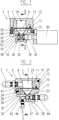
- Fig. 3
- zeigt eine Ansicht der Pumpe von oben.
- Fig. 1
- shows a vertical section through a diaphragm pump according to the invention along section line II (Fig. 2);
- Fig. 2
- shows a section according to II-II (Fig. 1); and
- Fig. 3
- shows a view of the pump from above.
In den Figuren ist die Membranpumpe ohne die für die Erfindung nicht wesentlichen Teile des hydraulischen Antriebssystems dargestellt. Dieser Teil wird auch Pumpkopf 1 genannt. Der nicht dargestellte hydraulische Antrieb wird am Anschluss 3 angeschlossen. Der Antrieb kann beliebig aus den an sich bekannten Systemen gewählt werden. Die Hydraulikflüssigkeit ist bevorzugt relativ dünnflüssig.In the figures, the diaphragm pump is without the hydraulic parts that are not essential to the invention Drive system shown. This part is also called
Im Inneren des Antriebsteils 5 des Pumpkopfs 1 befindet sich die Hydraulikkammer 7, die durch die erste, antriebsseitige Membran 9 abgeschlossen ist. Die Membran 9 liegt auf einer vertieften, die Öffnung der Hydraulikkammer 7 umgebenden Fläche 11 der Hydraulikkammerwand 13 auf. Die Membran 9 wird von einem gegen die Wand 13 geschraubten Befestigungsring gehalten, wozu eine geeignete Anzahl Schrauben 17 dienen.In the interior of the
Zur Entlüftung der Hydraulikkammer 7 ist eine Entlüftungsbohrung 19 vorhanden, die von einer Schraube 20 verschlossen ist.For venting the
Am Antriebsteil 5 ist unten das Pumpsystem 22 angebracht. Die Pumpkammer 24 im Pumpsystem 22 ist oben von der pumpenseitigen Membran, kurz Pumpmembran 26, abgeschlossen. Die Pumpmembran 26 liegt auf einer Dichtfläche 28 der Pumpkammerwand 30 auf. Sie wird am Rand vom Befestigungsring 15 eingefasst.The
Das Pumpsystem 22 ist mittels Schrauben 32 (Fig. 3) am Antriebsteil 5 angeschraubt. Beim Eindrehen und Anziehen der Schrauben 32 werden dabei die Membranen 9 und 26 gegeneinander und letztere gegen die Dichtfläche 28 gedrückt. Ein exakter Gleichlauf der Membranen 9 und 26 wird durch eine zwischen ihnen befindliche, blasenfreie Öl- oder Fettschicht erzielt. Die Membranen 9 und 26 bestehen bevorzugt aus Metall oder Kunststoff, müssen jedoch nicht aus demselben Material bestehen.The
Unten an der Pumpkammerwand 30 ist die Ventileinheit 36 mittels Schrauben 38 befestigt. Zur Abdichtung der Trennfläche dient ein O-Ring 40. Zur Entlüftung weist die Pumpkammer 24 noch eine durch z. B. eine Schraube verschliessbare Entlüftungsöffnung 41 auf.At the bottom of the
Die Ventileinheit 36 besteht aus einem Drei-Wege-Drehschieberventil 42, das den Zugang zur Pumpkammer 24 mit dem Einlass 44 für das Arbeitsmedium oder alternativ mit dem Auslass 46 verbinden kann.The
Das Ventil 42 wird von einem eigenen Antrieb 45 betätigt. Dieser Antrieb muss mit dem hydraulischen Antrieb synchronisiert werden, wozu eine nicht dargestellte Steuerung dient. Derartige Steuerungen sind an sich bekannt, wie auch das Ventil 42. Das Ventil 42 besteht z. B. aus einem walzenförmigen Ventilkörper. Der Ventilkörper enthält eine um 90° abgewinkelte Bohrung 47. Der Ventilkörper 48 ist in einer Büchse 49 drehbar angeordnet. Zur Abdichtung zwischen Ventilkörper 48 und Büchse 49 befinden sich zwei O-Ringe 50 jeweils oberhalb und unterhalb der Bohrung 47, desgleichen zwischen der Büchse 49 und dem Gehäuse der Ventileinheit 36 zwei weitere O-Ringe 52.The
Der Auslass 46 ist als Düse gestaltet. Bei den bevorzugten, pastösen oder hochviskosen Arbeitsmedien kann so ein freies Ausfliessen verhindert werden, wodurch unter anderem exaktes Dosieren möglich ist.The
Die vorliegende Erfindung ist besonders zum Fördern von hochviskosen oder pastösen Materialien geeignet, die auch abrasive Stoffe enthalten können. Diese führen zu einem raschen Verschleiss der bewegten Teile und damit unter anderem zu Dosierungsfehlern. Durch Auswechseln in entsprechend kurzen Intervallen, das mit der vorliegenden Erfindung ohne lange Betriebsunterbrechungen möglich ist, kann diesen nachteiligen Auswirkungen der Abnutzung entgegengewirkt werden. Ein verschlissener Pumpteil kann, nachdem er vom Antriebssystem entfernt wurde, parallel zum Weiterbetrieb der Pumpe instandgesetzt werden. Insbesondere ist es auch denkbar, besonders dem Verschleiss unterworfene Teile aus weniger widerstandsfähigem, jedoch preiswerterem und/oder leichter zu entsorgendem Material auszuführen, z. B. die Ventileinheit. Es ist daher denkbar, dass das gesamte Pumpteil oder z. B. das Ventil als bewegliches Teil aus einem preiswerterem, aber nicht extrem standfesten Metall oder einem Kunststoff besteht.The present invention is particularly suitable for conveying highly viscous or pasty materials, which can also contain abrasive substances. These lead to rapid wear of the moving parts and thus, among other things, dosing errors. By changing in correspondingly short intervals, the one with the present Invention is possible without long downtimes, these adverse effects of wear and tear can be counteracted. After it has been removed from the drive system, a worn pump part can be repaired in parallel with the continued operation of the pump. In particular, it is also conceivable to carry out, in particular, parts subject to wear from less resistant, but cheaper and / or easier to dispose of material, e.g. B. the valve unit. It is therefore conceivable that the entire pump part or z. B. the valve as a moving part consists of a cheaper, but not extremely stable metal or plastic.
Der Anbau des Pumpsystems an das Antriebsteil kann so erfolgen, dass zunächst ein Hydrauliköl auf die Membran 9 aufgebracht und dann die Membran 26 aufgelegt wird. Dabei wird darauf geachtet, dass sich zwischen den Membranen keine Luftblasen befinden. Am einfachsten geschieht dies durch visuelle Kontrolle. Dann wird das eigentliche Pumpsystem angesetzt und mittels der Schrauben 34 befestigt. Das Pumpsystem wird mit dem Arbeitsmedium gefüllt, wobei die Pumpkammer 24 über die Entlüftungsbohrung 41 entlüftet wird.The pump system can be attached to the drive part in such a way that a hydraulic oil is first applied to the
Das Abnehmen des Pumpsystems erfolgt im wesentlichen in umgekehrter Reihenfolge. Es ist also weder beim Anbau noch beim Entfernen des Pumpsystems nötig, das Antriebssystem zu öffnen, was unter anderem ein Entlüften der Hydraulik nach sich ziehen würde.The pumping system is essentially removed in the reverse order. It is therefore not necessary to open the drive system when installing or removing the pump system, which would entail venting the hydraulics, among other things.
Eine mögliche Variante besteht darin, direkt einen Kolben in die Hydraulikkammer anzuordnen. Durch Einschieben und Herausziehen des Kolbens synchron mit der Steuerung des Ein-/Auslassventils kann dann gepumpt werden. Der Hydraulikanschluss wird dann nicht mehr benötigt, obwohl beide Antriebsarten auch parallel benutzt werden können.One possible variant is to place a piston directly in the hydraulic chamber. It is then possible to pump by pushing in and pulling out the piston in synchronization with the control of the intake / exhaust valve. The hydraulic connection is then no longer required, although both types of drive can also be used in parallel.
Möglich ist auch, statt eines 3-Weg-Ventils ein dediziertes Ein- und ein Auslassventil vorzusehen.It is also possible to provide a dedicated inlet and outlet valve instead of a 3-way valve.
Die beschriebenen Membranpumpen sind bevorzugt für kleine Volumen bis etwa 1 ml Ausstoss pro Pumpzyklus ausgelegt. Die Membranen bestehen bevorzugt aus Silikon und weisen eine Dicke von etwa 1 mm auf. Membranen aus Metall, bevorzugt aus Stahl, sind beispielsweise 0,2 - 0,3 mm dick. Die Membranpumpen eignen sich insbesondere zum Befördern dickflüssiger und/oder mit abrasiven Materialien beladener Medien.The membrane pumps described are preferably designed for small volumes up to approximately 1 ml output per pump cycle. The membranes are preferably made of silicone and have a thickness of approximately 1 mm. Membranes made of metal, preferably made of steel, are for example 0.2-0.3 mm thick. The diaphragm pumps are particularly suitable for conveying viscous media and / or media loaded with abrasive materials.
Die Membranpumpen sind auch dort vorteilhaft einsetzbar, wo hoher Verschleiss der Pumpe durch korrodierende Eigenschaften der zu fördernden Medien auftritt.The diaphragm pumps can also be used advantageously where there is high wear on the pump due to corrosive properties of the media to be pumped.
Claims (11)
Applications Claiming Priority (2)
| Application Number | Priority Date | Filing Date | Title |
|---|---|---|---|
| CH2055/94 | 1994-06-28 | ||
| CH205594 | 1994-06-28 |
Publications (1)
| Publication Number | Publication Date |
|---|---|
| EP0690232A1 true EP0690232A1 (en) | 1996-01-03 |
Family
ID=4224873
Family Applications (1)
| Application Number | Title | Priority Date | Filing Date |
|---|---|---|---|
| EP95810368A Withdrawn EP0690232A1 (en) | 1994-06-28 | 1995-06-06 | Membrane pump |
Country Status (1)
| Country | Link |
|---|---|
| EP (1) | EP0690232A1 (en) |
Cited By (3)
| Publication number | Priority date | Publication date | Assignee | Title |
|---|---|---|---|---|
| EP0947814A2 (en) * | 1998-03-30 | 1999-10-06 | Fresenius Medical Care Deutschland GmbH | Procedure for obtaining an airtight connection between two diaphragms |
| CN103423149A (en) * | 2013-08-05 | 2013-12-04 | 宝鸡航天动力泵业有限公司 | Membrane pump membrane quick replacing type compression mechanism |
| EP3441612A1 (en) * | 2017-08-08 | 2019-02-13 | Scheugenpflug AG | Pumping unit, storage device equipped with the same and method for operating said storage device |
Citations (5)
| Publication number | Priority date | Publication date | Assignee | Title |
|---|---|---|---|---|
| GB283021A (en) * | 1927-03-28 | 1928-01-05 | Jean Donat Julien | Improvements relating to pumps |
| EP0441681A1 (en) * | 1990-02-08 | 1991-08-14 | DOSAPRO MILTON ROY, SociÀ©té dite: | Improvement in a diaphragm failure detection device for a double diaphragm pump |
| DE9004560U1 (en) * | 1990-04-23 | 1991-08-22 | Bran + Luebbe Gmbh, 2000 Norderstedt, De | |
| DE4136097C1 (en) * | 1991-11-02 | 1993-03-04 | Kloeckner Haensel Gmbh, 3000 Hannover, De | |
| US5282849A (en) * | 1991-12-19 | 1994-02-01 | University Of Utah Research Foundation | Ventricle assist device with volume displacement chamber |
-
1995
- 1995-06-06 EP EP95810368A patent/EP0690232A1/en not_active Withdrawn
Patent Citations (5)
| Publication number | Priority date | Publication date | Assignee | Title |
|---|---|---|---|---|
| GB283021A (en) * | 1927-03-28 | 1928-01-05 | Jean Donat Julien | Improvements relating to pumps |
| EP0441681A1 (en) * | 1990-02-08 | 1991-08-14 | DOSAPRO MILTON ROY, SociÀ©té dite: | Improvement in a diaphragm failure detection device for a double diaphragm pump |
| DE9004560U1 (en) * | 1990-04-23 | 1991-08-22 | Bran + Luebbe Gmbh, 2000 Norderstedt, De | |
| DE4136097C1 (en) * | 1991-11-02 | 1993-03-04 | Kloeckner Haensel Gmbh, 3000 Hannover, De | |
| US5282849A (en) * | 1991-12-19 | 1994-02-01 | University Of Utah Research Foundation | Ventricle assist device with volume displacement chamber |
Cited By (7)
| Publication number | Priority date | Publication date | Assignee | Title |
|---|---|---|---|---|
| EP0947814A2 (en) * | 1998-03-30 | 1999-10-06 | Fresenius Medical Care Deutschland GmbH | Procedure for obtaining an airtight connection between two diaphragms |
| EP0947814A3 (en) * | 1998-03-30 | 2000-04-05 | Fresenius Medical Care Deutschland GmbH | Procedure for obtaining an airtight connection between two diaphragms |
| US6484383B1 (en) | 1998-03-30 | 2002-11-26 | Fresenius Medical Care Deutschland Gmbh | Method of airtight bonding of two membranes |
| CN103423149A (en) * | 2013-08-05 | 2013-12-04 | 宝鸡航天动力泵业有限公司 | Membrane pump membrane quick replacing type compression mechanism |
| CN103423149B (en) * | 2013-08-05 | 2015-08-19 | 宝鸡航天动力泵业有限公司 | Diaphragm of diaphragm pump quick replacable type hold-down mechanism |
| EP3441612A1 (en) * | 2017-08-08 | 2019-02-13 | Scheugenpflug AG | Pumping unit, storage device equipped with the same and method for operating said storage device |
| WO2019030001A1 (en) * | 2017-08-08 | 2019-02-14 | Scheugenpflug Ag | Pump unit, storage device equipped therewith, and method for operating the storage device |
Similar Documents
| Publication | Publication Date | Title |
|---|---|---|
| DE2127976A1 (en) | Dosing piston pump | |
| DE4407679A1 (en) | Bellow pump | |
| DE102006025653C5 (en) | Aseptic double-seat valve | |
| DE3152349A1 (en) | Back-flow prevention valve | |
| EP0690232A1 (en) | Membrane pump | |
| DE102009048721B4 (en) | pumping device | |
| EP0605471A1 (en) | Swash pump. | |
| EP0203980B1 (en) | Device for providing individual spray systems of pressure casting machines with a liquid containing water and additives | |
| DE69815879T2 (en) | valve assembly | |
| DE4422819A1 (en) | High-pressure pump | |
| DE1911919C3 (en) | Diaphragm pump for dosing liquids | |
| DE3507011A1 (en) | Liquid-conveying apparatus, preferably for colorants and chemicals | |
| DE102017117983A1 (en) | Pump unit, bearing device equipped therewith and method of operating the bearing device | |
| DE19516578C1 (en) | Internal gearwheel pump for continuous sterile cleaning | |
| EP0679806A2 (en) | Pump for flowable, in particular pasty matérials, in particular for a medical laboratory | |
| DE202006019205U1 (en) | Seal for viscous fluid pump has housing containing sliding seal ring, throttle ring and fixed seal for use when pump shaft is not rotating | |
| DE3710013A1 (en) | Diaphragm positive-displacement pump, in particular for abrasive, corrosive liquids with suspended particles, or the like | |
| DE102017126651A1 (en) | Pumping device with coupled via a common drive pumps | |
| DE60127467T2 (en) | Continuous displacement metering valve | |
| DE2552828A1 (en) | Reciprocating sludge pump unit - has auxiliary piston providing protective clean fluid flow to moving parts of sludge piston | |
| DE962498C (en) | Diaphragm pump | |
| EP0301016A1 (en) | Device for metering and mixing systems of multiple fluid components. | |
| EP1454063B1 (en) | Feed pump | |
| AT521891A1 (en) | Valve | |
| DE1033514B (en) | Pumps with pulsating operation |
Legal Events
| Date | Code | Title | Description |
|---|---|---|---|
| PUAI | Public reference made under article 153(3) epc to a published international application that has entered the european phase |
Free format text: ORIGINAL CODE: 0009012 |
|
| AK | Designated contracting states |
Kind code of ref document: A1 Designated state(s): CH DE FR IT LI NL |
|
| K1C1 | Correction of patent application (title page) published |
Effective date: 19960103 |
|
| STAA | Information on the status of an ep patent application or granted ep patent |
Free format text: STATUS: THE APPLICATION IS DEEMED TO BE WITHDRAWN |
|
| 18D | Application deemed to be withdrawn |
Effective date: 19960704 |