EP0690407A2 - Image recognition apparatus and method - Google Patents
Image recognition apparatus and method Download PDFInfo
- Publication number
- EP0690407A2 EP0690407A2 EP95304594A EP95304594A EP0690407A2 EP 0690407 A2 EP0690407 A2 EP 0690407A2 EP 95304594 A EP95304594 A EP 95304594A EP 95304594 A EP95304594 A EP 95304594A EP 0690407 A2 EP0690407 A2 EP 0690407A2
- Authority
- EP
- European Patent Office
- Prior art keywords
- recognition
- input
- image
- locus
- shapes
- Prior art date
- Legal status (The legal status is an assumption and is not a legal conclusion. Google has not performed a legal analysis and makes no representation as to the accuracy of the status listed.)
- Granted
Links
Images


Classifications
-
- G—PHYSICS
- G06—COMPUTING; CALCULATING OR COUNTING
- G06V—IMAGE OR VIDEO RECOGNITION OR UNDERSTANDING
- G06V30/00—Character recognition; Recognising digital ink; Document-oriented image-based pattern recognition
- G06V30/10—Character recognition
- G06V30/24—Character recognition characterised by the processing or recognition method
- G06V30/242—Division of the character sequences into groups prior to recognition; Selection of dictionaries
-
- G—PHYSICS
- G06—COMPUTING; CALCULATING OR COUNTING
- G06F—ELECTRIC DIGITAL DATA PROCESSING
- G06F18/00—Pattern recognition
Definitions
- Present invention relates to a data input apparatus for inputting operation commands, character data and other type of data, using an input pen and a digitizer, and a data input method for the apparatus.
- Conventional pen-input electronic devices usually have gesture-command input function that allows a user to pen-input operation commands in character-input mode or locus-input mode.
- gesture-command input if a predetermined input locus is recognized, the command corresponding to the input locus operates.
- the user may need to change input modes so often that the input operation is not smooth, meaning, the manual mode-change operation will be troublesome.
- the pen-input device does not have command-input mode
- the input loci used as gesture commands otherwise shapes recognizable as characters or figures are limited. For this reason, the user cannot use, e.g., shapes which are intuitively recognizable by the user, as gesture commands. Further, as input characters are limited, some characters cannot be easily inputted. Furthermore, it is confusing for the user when a command is inputted with different gestures in respective figure-input mode and character-input mode.
- a gesture command "X" (delete) is effective when character-input is not made, however, in character-input mode, the input "X" is treated as an alphabet.
- a gesture command " ⁇ " (undo) exists, a Greek letter " ⁇ " cannot be inputted.
- the present invention has been made in consideration of the above situation, and has as a concern to provide an image recognition apparatus and method which distinguishes the purposes of locus-inputs, and recognizes input loci which are similar but of different mode types, without confusion.
- an image recognition apparatus comprising: recognition means having a plurality of recognition modes such as figure recognition mode for recognizing an input image as a figure code, character recognition mode for recognizing the input image as a character code, gesture recognition mode for recognizing the input image as a command; recognition determination means for determining one of the recognition mode as available recognition mode; similarity judgment means for judging whether the image recognizable in one of the plurality of recognition modes is also recognizable in another one of the plurality of recognition modes; and selection image display means for, if the image recognizable in a plurality of recognition modes, displaying candidate code(s) for a recognition(s) result, for the user's selection.
- recognition means having a plurality of recognition modes such as figure recognition mode for recognizing an input image as a figure code, character recognition mode for recognizing the input image as a character code, gesture recognition mode for recognizing the input image as a command; recognition determination means for determining one of the recognition mode as available recognition mode; similarity judgment means for judging whether the image recognizable in one of the plurality of recognition
- the similarity judgment means performs similarity judgment based on input judgment reference value.
- the image recognition apparatus and method can perform recognition in accordance to the user's intention.
- the present invention is advantageous since the user can clearly designate recognition processing to an input locus, further, the above-mentioned limitations on gestures, characters and the like are removed. This avoids confusing input operation and eliminates time-wasting storing of gestures in different modes used as the same command.
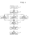
- Fig. 1 shows the construction of an input apparatus such as a pen computer, according to a first embodiment of the present invention. This construction operates to send pen-inputted data to the next process step executed by, e.g., an application program.
- Fig. 10 shows a data system comprising the data input apparatus 1001 which has the construction in Fig. 1 and a data processing apparatus 1002.
- the data processing apparatus 1002 inputs data from an data input apparatus 1001.
- a locus input unit 1 performs locus-input processing to send locus data, inputted from a digitizer with an input-pen, in recognizable unit, to the subsequent processing.
- a mode discrimination unit 2 sends the input locus data to any of recognition units 3 to 5, in accordance with available recognition mode such as character-recognition mode, figure-recognition mode, command-recognition mode etc. If a plurality of recognition modes are available, the mode discrimination unit 2 sends the input locus data to plural recognition units.
- the available modes are set prior to locus input by a user of the input apparatus, i.e., an application according to sorts of data which are used by the user.
- the recognition units 3 to 5 respectively confirm the shape of input locus and obtain a corresponding code.
- the figure recognition unit 3 determines a predetermined figure similar to received locus data (image), and a figure code indicative of the kind of figure and similarity data representing the similarity between the predetermined figure and the input locus data by percentage, to the next processing.
- the character recognition unit 4 sends a character code recognized from received locus data and similarity data to the next processing.
- the gesture recognition unit 5 sends a gesture code indicative of the type of command and similarity data to the next processing.
- the recognition algorithm and similarity calculation method used in the recognition units 3 to 5 may be prior art methods used in computers as well-known techniques.
- an input locus is analyzed into line segments, and phase-structure features of, e.g., a loop, a dot, concavity and convexity are extracted, and the extracted features are compared with features of characters or figures.
- the similarities are given in accordance with the number of coincident features.
- a similarity judgment unit 6 compares the similarity sent from the plurality of recognition units. That is, regarding one image, the similarity judgment unit 6 determines whether or not the image is a polychrestic image, from which a unique code cannot be recognized in one recognition mode but a plurality of codes in respective plural recognition modes can be recognized.
- selection image display unit 7 displays the selection images for a user to designate a recognition mode.
- An input data determination unit 8 outputs data finally determined as the result from recognition or user's selection to the data processing apparatus 1002.
- Figs. 2A and 2B show examples of the selection image displayed by the selection image display unit 7.
- the display has a window 201 displaying a shape "X" with a selection button A1 indicating "deletion command”, and a window 202 displaying an alphabet "X” with a selection button A2 indicating “character”.
- the user sees the selection image and knows that the data input apparatus 1001 cannot recognize the input, then selects the appropriate selection buttons A1 or A2 with the input pen. If the user did not intend command input and character input and wants to cancel the input itself, the user presses an undo button B. Then, the input locus data is deleted and the process returns to the state before the deleted data was inputted. Also, a recognition result can be canceled.
- the selection image has a selection button C indicating "stroke". If the user presses this button, only the result from the recognition of the input locus data is deleted, and the locus data remains in a window 203. For example, in use of graphic application, the user may simply input strokes. As the recognition processing is not desired, the user presses the stroke selection button C to delete only the recognition result, and the input data determination unit 8 outputs the input strokes to the next processing or the data processing apparatus 1002.
- Fig. 3 shows the processing that starts when input loci are accumulated to a predetermined amount in the locus input unit 1, and performs respective processing by the blocks 2 to 7 in Fig. 1.
- the locus input unit 1 divides the input locus data with stroke units, as one stroke being an interval between a contact time where the input pen touches an input surface and a pen-up time where the input pen is picked up from the input surface.
- the locus input unit 1 regards the strokes inputted by that time as one set of symbol-structure data, and sends the set of data to the next processing.
- This locus-data dividing may be performed by "character cut-out" processing in handwritten character recognition, where input strokes are divided into a single character.
- Various well-known techniques are available as character cut-out processing.
- Fig. 9 also shows the construction of the data input apparatus 1001 shown in Fig. 10.
- locus data hand-written from a digitizer 901 is displayed on a display panel 903, and subjected to recognition processing by a CPU 902, as a character, a figure or a command.
- the CPU 902 performs necessary processing by executing a program stored in a RAM 904 or a ROM 905.
- the processings by the respective units in Fig. 1 are realized by the execution of programs by the CPU 902.
- the digitizer 901 in a case where the digitizer 901 comprises a transparent member, the digitizer 901 is overlaid on the display panel 903 so that the display panel 903 displays a locus as if it traces input from the digitizer. This attains more natural handwritten input.
- step S2 the mode discrimination unit 2 checks available recognition mode(s) in the current application program, and sets a value "1" to a mode flag fg of the available recognition mode.
- the flag values are fg(0), fg(1) and fg(2), respectively for figure recognition, character recognition and gesture recognition. In this embodiment, these flags are prepared in accordance with recognition processings by the application program. To perform recognition of pen input in use of application program or utility program, recognition processings can be determined in designing of the program, and set in advance as this embodiment.
- the application when an application which functions as a note pad is triggered, the application accepts only character input and gesture input, accordingly, the application sets the necessary recognition modes to a memory area.
- the flags fg(0) to fg(2) are set corresponding to the stored contents.
- the flags fg(1) and fg(2) are set to "1".
- step S3 to S8 in which the respective flags fg(0) to fg(2) are checked and recognition processing corresponding to a set flag value is executed to the set of strokes sent from the locus input unit 1.
- a recognized code and similarity between the recognized code and the input data i.e., the reliability of the recognition result are obtained.
- the similarity data is represented by percentage where "100" means complete match, and "0" means the opposite.
- steps S5 and S7 it is determined that the values of flags fg(1) and fg(2) are "1", and character recognition and gesture recognition are respectively performed in steps S6 and S8.
- values indicating the recognition results are respectively set as a recognized character code1, its similarity r1, a recognized gesture code code2, and its similarity r2.
- an alphabet letter "X” is set as the code 1
- a deletion gesture code is set as the code 2
- "85” is set to the similarity r1
- "70” is set as the similarity r2.
- the flag fg(0) is "0”
- figure recognition is not performed, and a recognized figure code code0 and its similarity r0 have no value. Note that "0" of the similarity r0 means " no match".
- step S9 the maximum value among the similarities r0 to r2 are stored as mr.
- the value 85 is stored as mr.
- step S10 whether or not the mr value is greater than a predetermined threshold value is determined. In this example, value "70" is set as a threshold value between relatively high values and relatively not-so high values. If the maximum similarity mr is equal to the threshold value or greater, i.e., recognized result has a predetermined or higher reliability, the process proceeds to step S11, while if not, it is determined that no code has been recognized, and the process ends. Note that if the similarity is equal to the predetermined value or greater, it is considered that the recognition has been successful.
- step S11 whether or not there is any similarity r closest to the maximum similarity mr is checked.
- the gesture similarity r2 is determined as the closest similarity. This determination is made based on existence/absence of another similarity within a predetermined range. In this example, the predetermined range is "20".
- the process proceeds to step S12 in which a selection image is outputted, then, as the user selects one mode, the recognition result in the selected mode is stored in a recognized-code storage area rcode, and the process ends. If there is no other similarity in step S11, the process proceeds to step S13 and the code of the maximum similarity mr is stored into the recognized-code storage area rcode, and the process ends.
- gesture recognition is performed and a deletion command is recognized.
- a deletion command is stored as the recognized gesture code code2, and a similarity value "70" is set as the similarity r2 (step S8).
- the similarity value r1 (85) is set as the maximum similarity mr (step S9), and whether or not the maximum similarity mr value is 70 or greater (step S10).
- the user selects the "character” selection button A2 if he/she user wants to input “X” as a character, while selects the “deletion command” selection button A1 if he/she wants to input “X” as a command. If the user wants to input "X” as strokes, he/she selects the "stroke” selection button C. Then, a selected code is stored in the area rcode as input data. Note that if the "stroke” button C is pressed, no code is inputted.
- the similarity in the present embodiment may be replaced with any value so far as it indicates reliability of recognition. Further, the range of the value may be arbitrarily set. Since the present embodiment needs only rough reliability judgment, the values used in steps S10 and S11 may be set corresponding to the level of reliability.
- the similarities r, the recognized codes rcode, mode flags fg may be increased in accordance with recognition processings.
- Fig. 4 shows a selection image for setting the relation among a plurality of recognition processings, of the data input apparatus 1001 according to a second embodiment of the present invention.
- This embodiment basically has the same construction as that of the first embodiment, except that the operation in the flowchart of Fig. 5 is different in some steps from that of Fig. 3. The difference from the first embodiment will be described with reference to Figs. 4 and 5.
- a slide 10 is used for setting parameter of displaying a selection image.
- the parameter is a reference value for determining the similarity.
- a selection image is not displayed often even if a plurality of codes with in a plurality of recognition modes are picked up as very similar to each other.
- the slider 101 is moved rightward, a selection image is often displayed even if picked-up codes are not so similar to each other.
- the range value (20 in step S11) for comparing the maximum similarity mr with its close value is changed by manipulating the parameter setting slide 10.
- this range value is fixed, however, in this embodiment, a value set by the slide 10 is stored into a storage area, and it is read out of the storage area at each processing. For example, assuming that the value of the left end position of the slide 10 is "0" and that of the right end position is "40", a value between these set values is linearly set depending upon the position of the slider 101 and stored in a storage area rr. In step S11' in Fig. 5, the value is read out of the storage area rr, and whether or not a value (mr-rr) exists is examined. In this manner, the user can arbitrarily change the parameter for selection-image displaying.
- numerals 11 to 13 denote areas for setting priority of respective recognition modes.
- the priorities are determined by respectively inputting numerals corresponding to the areas. For example, if the areas 11 to 13 all have a value "100”, gesture recognition, character recognition and figure recognition all have the same priority. When the areas 11 to 13 have values "100", "70” and “70” respectively, gesture recognition has a higher priority than other recognition modes.
- the input values are percentage values to be used in multiplication of the recognition similarities. Actually, in step S8.5, the respective recognition similarities are multiplied by the set percentages.
- a selection image is outputted for the user to select a recognition mode, similar to the processing in Fig. 3.
- input of percentage values are made before locus input.
- Fig. 5 shows the operation as described above in detail.
- the processing in Fig. 5 is basically the same as that in Fig. 3 except additional steps S8.5, S10.5 and modified step S11'.
- step S8.5 to control the priorities of recognitions, the respective similarities are multiplied with input percentage values.
- step S10.5 to control selection-image display frequency, a set value is read out of the storage area rr.
- step S11' a similarity range mr-rr is used.
- This processing allows the user to select one of command recognition (gesture recognition), character recognition, figure recognition and stroke input, if the system cannot clearly discriminate available recognition mode(s) with respect to an input locus. Accordingly, in each recognition processing, it is not necessary to consider other possible recognized shapes in other recognition process.
- the user can arbitrarily set the selection-image display parameter and the priorities of a plurality of recognition modes.
- Fig. 6 shows the construction of the data input apparatus 1001 according to a third embodiment of the present invention.
- a locus input unit 21 corresponds to the locus input 1 in Fig. 1; a mode discrimination unit 22, to the mode discrimination unit 2; a gesture recognition unit 23, to the gesture recognition unit 5, a selection image display unit 25, to the selection image display unit 7; a figure recognition unit 26, to the figure recognition unit 3; and a character recognition unit 27, to the character recognition unit 4.
- the similarity judgment unit 24 is different from the similarity judgment unit 6 in operation.
- Fig. 7 shows a similarity table used by the similarity judgment unit 24.
- the similarity table is included in the similarity judgment unit 24.
- a column 71 contains input loci; column 72, gesture codes; column 73, figure codes for discriminating figure type; and column 74, character codes.
- Fig. 7 conceptually illustrates the table with shapes instead of actual codes. Note that the input-locus column 71 does not exist in an actual similarity table.
- Fig. 7 shows the column 71 merely to show the corresponding codes for each input.
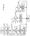
- Fig. 8 shows the processing procedure according to the third embodiment, i.e., processings by the gesture recognition unit 23 to the character recognition unit 27, to obtain a recognition result.
- the processing in Fig. 8 is realized by executing a program by the CPU 902 in Fig. 9.
- the operation of the third embodiment will be described below with reference to the flowchart of Fig. 8.
- step S800 the mode flags fg(0) to fg(2) are set in a similar manner to that in step S2 of the first embodiment.
- step S801 the gesture recognition unit 23 is activated, and a gesture code code2 and its similarity r2 are set as the recognition results.
- step S802 the similarity is checked. If the similarity r2 which is the reliability of the gesture recognition result is over a set threshold "70", i.e., the reliability is high, the process proceeds to step S803 in which the similarity table as shown in Fig. 7 is searched. This search is made by examining whether or not a gesture code in column 72 coincides with the code2.
- step S804 the process proceeds to step S805 in which a selection image is outputted, so that the user selects a desired recognition mode.
- the code of the selected mode is determined as the final recognized code, and the process ends.
- the selection image may be as shown in Figs. 2A and 2B.
- step S802 If it is determined in step S802 that the recognition reliability is not high, the process proceeds to steps S806 and S808, in which the mode flags fg(0) and fg(1) are checked, and figure recognition in step S807 or character recognition in step S808 is activated. Then, the recognized code is determined as the final recognition result, and the process ends.
- one shape can be commonly used in a plurality of recognition processings such as character recognition, command recognition and gesture recognition.
- the present embodiment uses only one recognition processing, i.e., the gesture recognition
- the present embodiment enables higher processing than the processing in the first embodiment, since the first embodiment activates all the recognition modes, while this embodiment perform recognition processing on one symbol-structure data by one recognition mode.
- the combination of the third embodiment with the first embodiment or the second embodiment will attain concurrent use of plurality of recognition processing with high speed.
- the input apparatus 1001 has the same construction as that of the third embodiment shown in Fig. 6, and has a similarity table as shown in Fig. 7.
- the difference from the third embodiment is the processing procedure shown in Fig. 11.
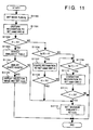
- the processing procedure according to the fourth embodiment will be described with reference to Fig. 11.
- step S1100 the mode flags fg(0) to fg(2) are set in a similar manner to that in step S2 of the first embodiment.
- step S1101 gesture recognition is performed, and the obtained code and its similarity are set as the recognized gesture code2 and the similarity r2.
- step S1102 the similarity value is examined whether it equal to a set threshold "70" or greater. If it is "70" or greater, the similarity table is searched in step S1103. The retrieved code is examined in step S1104, and if another code with high similarity exists, these codes are displayed in the form as shown in Fig. 2A or 2B for the user's selection. Then, the determined code is set as the final recognitfon result rcode. If there is no other code, the gesture code code2 is determined as the final recognition result.
- step S1106 determines whether or not figure recognition mode is set. If YES, figure recognition is performed in step S1107, and the obtained code and its similarity are set as the recognized figure code code0 and the similarity r0. Next, the similarity r0 is examined in step S1108, and if it is "70" or greater, the figure code0 is determined as the final recognition result.
- step S1109 If gesture recognition and figure recognition have not obtained a final recognition result, whether or not character recognition is set is examined in step S1109. If YES, character recognition is performed in step S1110, and the obtained code and its similarity are set as the recognized character code code1 and the similarity r1. If the similarity r1 is "70" or greater, the code 1 is determined as the final recognition result.
- the present invention can be applied to a system constituted by a plurality of devices, or to an apparatus comprising a single device. Furthermore, the invention is applicable also to a case where the object of the invention is attained by supplying a program to a system or apparatus.
Abstract
Description
- Present invention relates to a data input apparatus for inputting operation commands, character data and other type of data, using an input pen and a digitizer, and a data input method for the apparatus.
- Conventional pen-input electronic devices usually have gesture-command input function that allows a user to pen-input operation commands in character-input mode or locus-input mode.
- In gesture-command input, if a predetermined input locus is recognized, the command corresponding to the input locus operates. To discriminate an input locus from simply-inputted locus data, or to avoid confusion of gesture-command recognition with character and figure recognition, several limitations are introduced as follows.
- In character-input mode, an input locus hard to distinguish from a similar character cannot be used as a gesture command, otherwise, a character similar to an input locus used as a gesture command cannot be recognized. Also, in figure-input mode, shapes often used as figures such as O, X, and Δ cannot be used as gesture commands. Further, there is a case where the user needs to designate command-input mode or non-command-input mode.
- As described above, these limitations are made basically to prevent confusion of gesture-command input with other-type of input in the same input mode.
- However, in the case where the user designates the input mode, the user may need to change input modes so often that the input operation is not smooth, meaning, the manual mode-change operation will be troublesome.
- As mentioned above, if the pen-input device does not have command-input mode, the input loci used as gesture commands, otherwise shapes recognizable as characters or figures are limited. For this reason, the user cannot use, e.g., shapes which are intuitively recognizable by the user, as gesture commands. Further, as input characters are limited, some characters cannot be easily inputted. Furthermore, it is confusing for the user when a command is inputted with different gestures in respective figure-input mode and character-input mode.
- For example, a gesture command "X" (delete) is effective when character-input is not made, however, in character-input mode, the input "X" is treated as an alphabet. When a gesture command "γ" (undo) exists, a Greek letter "γ" cannot be inputted.
- In this manner, the conventional input systems have different gestures in different input modes regarding one input intention, and this is confusing to users.
- The present invention has been made in consideration of the above situation, and has as a concern to provide an image recognition apparatus and method which distinguishes the purposes of locus-inputs, and recognizes input loci which are similar but of different mode types, without confusion.
- It is a second concern of the present invention to provide a data input apparatus and method which enables pen-input with intuitive and user-recognizable images, each reflects user's intention exactly.
- According to the present invention, there is provided an image recognition apparatus comprising: recognition means having a plurality of recognition modes such as figure recognition mode for recognizing an input image as a figure code, character recognition mode for recognizing the input image as a character code, gesture recognition mode for recognizing the input image as a command; recognition determination means for determining one of the recognition mode as available recognition mode; similarity judgment means for judging whether the image recognizable in one of the plurality of recognition modes is also recognizable in another one of the plurality of recognition modes; and selection image display means for, if the image recognizable in a plurality of recognition modes, displaying candidate code(s) for a recognition(s) result, for the user's selection. This construction achieves exact recognition of input intended by the user, when the input image of figure, a character or command is recognizable by a plurality of recognition means.
- Note that the similarity judgment means performs similarity judgment based on input judgment reference value.
- As described above, in a case where a plurality of recognition modes are activated simultaneously, even if there are similar shapes which are often used in the respective modes, or even if recognition processing of input locus cannot be easily discriminated, the image recognition apparatus and method can perform recognition in accordance to the user's intention.
- The present invention is advantageous since the user can clearly designate recognition processing to an input locus, further, the above-mentioned limitations on gestures, characters and the like are removed. This avoids confusing input operation and eliminates time-wasting storing of gestures in different modes used as the same command.
- Further, it is not necessary for the recognition system designer to consider the limitations on shapes of input loci. This allows the recognition system designer to use any shape.
- Furthermore, in command-input, more intuitive and user-recognizable commands can be used.
- Other features and advantages of the present invention will be apparent from the following description taken in conjunction with the accompanying drawings, in which like reference characters designate the same or similar parts throughout the figures thereof.
- The accompanying drawings, which are incorporated in and constitute a part of the specification, illustrate embodiments of the invention and, together with the description, serve to explain the principles of the invention.
- Fig. 1 is a block diagram showing the construction of an input apparatus according to a first embodiment of the present invention;
- Figs. 2A and 2B are selection image examples in the first embodiment;
- Fig. 3 is a flowchart showing the operation of the first embodiment;
- Fig. 4 is an example of a selection image for selecting recognition mode(s) according to a second embodiment of the present invention;
- Fig. 5 is a flowchart showing the operation of the second embodiment;
- Fig. 6 is a block diagram showing the construction of the input apparatus according to a third embodiment of the present invention;
- Fig. 7 is an example of a similarity table in the third embodiment;
- Fig. 8 is a flowchart showing the operation of the third embodiment;
- Fig. 9 is a block diagram showing the input apparatus according to the third embodiment;
- Fig. 10 is a block diagram showing the construction of a data processing apparatus using the data input apparatus of the embodiments; and
- Fig. 11 is a flowchart showing the operation of a fourth embodiment of the present invention.
- Preferred embodiments of the present invention will be described in detail in accordance with the accompanying drawings.
- Fig. 1 shows the construction of an input apparatus such as a pen computer, according to a first embodiment of the present invention. This construction operates to send pen-inputted data to the next process step executed by, e.g., an application program.
- Fig. 10 shows a data system comprising the
data input apparatus 1001 which has the construction in Fig. 1 and adata processing apparatus 1002. In Fig. 10, thedata processing apparatus 1002 inputs data from andata input apparatus 1001. - In Fig. 1, a
locus input unit 1 performs locus-input processing to send locus data, inputted from a digitizer with an input-pen, in recognizable unit, to the subsequent processing. Amode discrimination unit 2 sends the input locus data to any ofrecognition units 3 to 5, in accordance with available recognition mode such as character-recognition mode, figure-recognition mode, command-recognition mode etc. If a plurality of recognition modes are available, themode discrimination unit 2 sends the input locus data to plural recognition units. The available modes are set prior to locus input by a user of the input apparatus, i.e., an application according to sorts of data which are used by the user. Therecognition units 3 to 5 respectively confirm the shape of input locus and obtain a corresponding code. Thefigure recognition unit 3 determines a predetermined figure similar to received locus data (image), and a figure code indicative of the kind of figure and similarity data representing the similarity between the predetermined figure and the input locus data by percentage, to the next processing. Thecharacter recognition unit 4 sends a character code recognized from received locus data and similarity data to the next processing. Similarly, thegesture recognition unit 5 sends a gesture code indicative of the type of command and similarity data to the next processing. The recognition algorithm and similarity calculation method used in therecognition units 3 to 5 may be prior art methods used in computers as well-known techniques. For example, an input locus is analyzed into line segments, and phase-structure features of, e.g., a loop, a dot, concavity and convexity are extracted, and the extracted features are compared with features of characters or figures. The similarities are given in accordance with the number of coincident features. Asimilarity judgment unit 6 compares the similarity sent from the plurality of recognition units. That is, regarding one image, thesimilarity judgment unit 6 determines whether or not the image is a polychrestic image, from which a unique code cannot be recognized in one recognition mode but a plurality of codes in respective plural recognition modes can be recognized. When the similarity judgment unit determines the input image is a polychrestic image, selection image display unit 7 displays the selection images for a user to designate a recognition mode. An inputdata determination unit 8 outputs data finally determined as the result from recognition or user's selection to thedata processing apparatus 1002. - Figs. 2A and 2B show examples of the selection image displayed by the selection image display unit 7. In Fig. 2A, the display has a
window 201 displaying a shape "X" with a selection button A1 indicating "deletion command", and awindow 202 displaying an alphabet "X" with a selection button A2 indicating "character". The user sees the selection image and knows that thedata input apparatus 1001 cannot recognize the input, then selects the appropriate selection buttons A1 or A2 with the input pen. If the user did not intend command input and character input and wants to cancel the input itself, the user presses an undo button B. Then, the input locus data is deleted and the process returns to the state before the deleted data was inputted. Also, a recognition result can be canceled. As shown in Fig. 2B, the selection image has a selection button C indicating "stroke". If the user presses this button, only the result from the recognition of the input locus data is deleted, and the locus data remains in awindow 203. For example, in use of graphic application, the user may simply input strokes. As the recognition processing is not desired, the user presses the stroke selection button C to delete only the recognition result, and the inputdata determination unit 8 outputs the input strokes to the next processing or thedata processing apparatus 1002. - Next, the processing in this example where the X-shaped locus is inputted with the input-pen and selection images in Figs. 2A and 2B are outputted, i.e., a case where character-recognition mode and gesture-recognition mode are available will be described with reference to the flowchart of Fig. 3.
- Fig. 3 shows the processing that starts when input loci are accumulated to a predetermined amount in the
locus input unit 1, and performs respective processing by theblocks 2 to 7 in Fig. 1. Thelocus input unit 1 divides the input locus data with stroke units, as one stroke being an interval between a contact time where the input pen touches an input surface and a pen-up time where the input pen is picked up from the input surface. When a predetermined time has elapsed since the stroke input started, thelocus input unit 1 regards the strokes inputted by that time as one set of symbol-structure data, and sends the set of data to the next processing. This locus-data dividing may be performed by "character cut-out" processing in handwritten character recognition, where input strokes are divided into a single character. Various well-known techniques are available as character cut-out processing. - Fig. 9 also shows the construction of the
data input apparatus 1001 shown in Fig. 10. In Fig. 9, locus data hand-written from adigitizer 901 is displayed on adisplay panel 903, and subjected to recognition processing by aCPU 902, as a character, a figure or a command. TheCPU 902 performs necessary processing by executing a program stored in aRAM 904 or aROM 905. The processings by the respective units in Fig. 1 are realized by the execution of programs by theCPU 902. Note that in Fig. 9, in a case where thedigitizer 901 comprises a transparent member, thedigitizer 901 is overlaid on thedisplay panel 903 so that thedisplay panel 903 displays a locus as if it traces input from the digitizer. This attains more natural handwritten input. - In Fig. 3, when a locus is inputted by the
locus input unit 1, storage areas r0 to r2 for storing similarity data are cleared to "0" in step S1. Next, in step S2, themode discrimination unit 2 checks available recognition mode(s) in the current application program, and sets a value "1" to a mode flag fg of the available recognition mode. The flag values are fg(0), fg(1) and fg(2), respectively for figure recognition, character recognition and gesture recognition. In this embodiment, these flags are prepared in accordance with recognition processings by the application program. To perform recognition of pen input in use of application program or utility program, recognition processings can be determined in designing of the program, and set in advance as this embodiment. For example, when an application which functions as a note pad is triggered, the application accepts only character input and gesture input, accordingly, the application sets the necessary recognition modes to a memory area. The flags fg(0) to fg(2) are set corresponding to the stored contents. In a case where a selection image is displayed, as shown in Figs. 2A and 2B, as character recognition and gesture recognition are available, the flags fg(1) and fg(2) are set to "1". - The process proceeds to step S3 to S8, in which the respective flags fg(0) to fg(2) are checked and recognition processing corresponding to a set flag value is executed to the set of strokes sent from the
locus input unit 1. As a result, a recognized code and similarity between the recognized code and the input data, i.e., the reliability of the recognition result are obtained. As mentioned above, the similarity data is represented by percentage where "100" means complete match, and "0" means the opposite. In this example, in steps S5 and S7, it is determined that the values of flags fg(1) and fg(2) are "1", and character recognition and gesture recognition are respectively performed in steps S6 and S8. Then, values indicating the recognition results are respectively set as a recognized character code1, its similarity r1, a recognized gesture code code2, and its similarity r2. In this example, an alphabet letter "X", is set as thecode 1, a deletion gesture code is set as thecode 2, and "85" is set to the similarity r1, and "70" is set as the similarity r2. As the value of the flag fg(0) is "0", figure recognition is not performed, and a recognized figure code code0 and its similarity r0 have no value. Note that "0" of the similarity r0 means " no match". - Next, in step S9, the maximum value among the similarities r0 to r2 are stored as mr. In this example, as the similarity r1 (85) is the greatest value, the value 85 is stored as mr. In step S10, whether or not the mr value is greater than a predetermined threshold value is determined. In this example, value "70" is set as a threshold value between relatively high values and relatively not-so high values. If the maximum similarity mr is equal to the threshold value or greater, i.e., recognized result has a predetermined or higher reliability, the process proceeds to step S11, while if not, it is determined that no code has been recognized, and the process ends. Note that if the similarity is equal to the predetermined value or greater, it is considered that the recognition has been successful.
- In step S11, whether or not there is any similarity r closest to the maximum similarity mr is checked. In this example, the gesture similarity r2 is determined as the closest similarity. This determination is made based on existence/absence of another similarity within a predetermined range. In this example, the predetermined range is "20". In this manner, if it is determined that there is another recognized code in another recognition mode, the process proceeds to step S12 in which a selection image is outputted, then, as the user selects one mode, the recognition result in the selected mode is stored in a recognized-code storage area rcode, and the process ends. If there is no other similarity in step S11, the process proceeds to step S13 and the code of the maximum similarity mr is stored into the recognized-code storage area rcode, and the process ends.
- Next, the case in Fig. 2B will be described in accordance with step S3 and the subsequent steps.
- In this example, character recognition and gesture recognition are performed (fg(1) = 1 and fg(2) = 1). Then, character recognition is performed and a character "X" is recognized. A character code "X" is stored as the recognized character code codel, and a similarity value "85" is set as the similarity r1 (step S6).
- Also, gesture recognition is performed and a deletion command is recognized. A deletion command is stored as the recognized gesture code code2, and a similarity value "70" is set as the similarity r2 (step S8).
- Next, the similarity value r1 (85) is set as the maximum similarity mr (step S9), and whether or not the maximum similarity mr value is 70 or greater (step S10). As mr = 85 > 70, whether or not there is recognized result with a similarity of 65 ((mr-20) = (85-20)) or greater is examined (step S11). Since the similarity value r2 of the gesture recognition result is 70 and satisfies the above condition, the selection image in Fig. 2B is displayed (step S12). The user selects the "character" selection button A2 if he/she user wants to input "X" as a character, while selects the "deletion command" selection button A1 if he/she wants to input "X" as a command. If the user wants to input "X" as strokes, he/she selects the "stroke" selection button C. Then, a selected code is stored in the area rcode as input data. Note that if the "stroke" button C is pressed, no code is inputted.
- Thus, if the system cannot make clear determination among discriminate command recognition (gesture recognition), character recognition, figure recognition, or stroke input, a selection image is displayed so that the user can select recognition mode. Accordingly, in each recognition mode, it is not necessary to consider any possible recognition code in another recognition mode.
- Note that the similarity in the present embodiment may be replaced with any value so far as it indicates reliability of recognition. Further, the range of the value may be arbitrarily set. Since the present embodiment needs only rough reliability judgment, the values used in steps S10 and S11 may be set corresponding to the level of reliability.
- When a plurality of recognition processings other than the above processings are used, the similarities r, the recognized codes rcode, mode flags fg may be increased in accordance with recognition processings.
- Fig. 4 shows a selection image for setting the relation among a plurality of recognition processings, of the
data input apparatus 1001 according to a second embodiment of the present invention. This embodiment basically has the same construction as that of the first embodiment, except that the operation in the flowchart of Fig. 5 is different in some steps from that of Fig. 3. The difference from the first embodiment will be described with reference to Figs. 4 and 5. - In Fig. 4, a
slide 10 is used for setting parameter of displaying a selection image. The parameter is a reference value for determining the similarity. When theslider 101 is moved leftward, a selection image is not displayed often even if a plurality of codes with in a plurality of recognition modes are picked up as very similar to each other. On the other hand, when theslider 101 is moved rightward, a selection image is often displayed even if picked-up codes are not so similar to each other. Thus, the range value (20 in step S11) for comparing the maximum similarity mr with its close value is changed by manipulating theparameter setting slide 10. In the first embodiment, this range value is fixed, however, in this embodiment, a value set by theslide 10 is stored into a storage area, and it is read out of the storage area at each processing. For example, assuming that the value of the left end position of theslide 10 is "0" and that of the right end position is "40", a value between these set values is linearly set depending upon the position of theslider 101 and stored in a storage area rr. In step S11' in Fig. 5, the value is read out of the storage area rr, and whether or not a value (mr-rr) exists is examined. In this manner, the user can arbitrarily change the parameter for selection-image displaying. - In Fig. 4,
numerals 11 to 13 denote areas for setting priority of respective recognition modes. The priorities are determined by respectively inputting numerals corresponding to the areas. For example, if theareas 11 to 13 all have a value "100", gesture recognition, character recognition and figure recognition all have the same priority. When theareas 11 to 13 have values "100", "70" and "70" respectively, gesture recognition has a higher priority than other recognition modes. The input values are percentage values to be used in multiplication of the recognition similarities. Actually, in step S8.5, the respective recognition similarities are multiplied by the set percentages. In a case where the percentages are 100: 70: 70, the recognition similarities r are, r0= r0 * 0.7, r1 = r1 * 0.7, r2 = r2 * 1.0; i.e., the similarities of figure recognition and character recognition are lowered, and as a result, an input locus is likely to be recognized as a gesture command. Note that if there are codes very similar to each other, a selection image is outputted for the user to select a recognition mode, similar to the processing in Fig. 3. In Fig. 4, input of percentage values are made before locus input. - Fig. 5 shows the operation as described above in detail. The processing in Fig. 5 is basically the same as that in Fig. 3 except additional steps S8.5, S10.5 and modified step S11'. In step S8.5, to control the priorities of recognitions, the respective similarities are multiplied with input percentage values. In step S10.5, to control selection-image display frequency, a set value is read out of the storage area rr. In step S11', a similarity range mr-rr is used.
- This processing allows the user to select one of command recognition (gesture recognition), character recognition, figure recognition and stroke input, if the system cannot clearly discriminate available recognition mode(s) with respect to an input locus. Accordingly, in each recognition processing, it is not necessary to consider other possible recognized shapes in other recognition process. In addition, in this embodiment, the user can arbitrarily set the selection-image display parameter and the priorities of a plurality of recognition modes.
- Fig. 6 shows the construction of the
data input apparatus 1001 according to a third embodiment of the present invention. - In Fig. 6, the respective blocks look similar to those in Fig. 1, however, the construction is different from that of Fig. 1. This embodiment performs gesture recognition for all locus inputs, further avoids confusion of gesture recognition.
- In Fig. 6, a
locus input unit 21 corresponds to thelocus input 1 in Fig. 1; amode discrimination unit 22, to themode discrimination unit 2; agesture recognition unit 23, to thegesture recognition unit 5, a selectionimage display unit 25, to the selection image display unit 7; afigure recognition unit 26, to thefigure recognition unit 3; and acharacter recognition unit 27, to thecharacter recognition unit 4. Note that thesimilarity judgment unit 24 is different from thesimilarity judgment unit 6 in operation. - Fig. 7 shows a similarity table used by the
similarity judgment unit 24. The similarity table is included in thesimilarity judgment unit 24. In Fig. 7, acolumn 71 contains input loci;column 72, gesture codes;column 73, figure codes for discriminating figure type; andcolumn 74, character codes. For simplicity of explanation, Fig. 7 conceptually illustrates the table with shapes instead of actual codes. Note that the input-locus column 71 does not exist in an actual similarity table. Fig. 7 shows thecolumn 71 merely to show the corresponding codes for each input. - Fig. 8 shows the processing procedure according to the third embodiment, i.e., processings by the
gesture recognition unit 23 to thecharacter recognition unit 27, to obtain a recognition result. The processing in Fig. 8 is realized by executing a program by theCPU 902 in Fig. 9. The operation of the third embodiment will be described below with reference to the flowchart of Fig. 8. - In step S800, the mode flags fg(0) to fg(2) are set in a similar manner to that in step S2 of the first embodiment.
- In step S801, the
gesture recognition unit 23 is activated, and a gesture code code2 and its similarity r2 are set as the recognition results. Next, the process proceeds to steps S802 and S803 for similarity judgment. In step S802, the similarity is checked. If the similarity r2 which is the reliability of the gesture recognition result is over a set threshold "70", i.e., the reliability is high, the process proceeds to step S803 in which the similarity table as shown in Fig. 7 is searched. This search is made by examining whether or not a gesture code incolumn 72 coincides with the code2. For example, when alocus 701 is inputted and a code 702 is recognized as the recognition result, it is determined that afigure code 703 and acharacter code 704 correspond to theinput locus 701. Then, thesecodes - If it is determined in step S802 that the recognition reliability is not high, the process proceeds to steps S806 and S808, in which the mode flags fg(0) and fg(1) are checked, and figure recognition in step S807 or character recognition in step S808 is activated. Then, the recognized code is determined as the final recognition result, and the process ends.
- Thus, one shape can be commonly used in a plurality of recognition processings such as character recognition, command recognition and gesture recognition. Although the present embodiment uses only one recognition processing, i.e., the gesture recognition, the present embodiment enables higher processing than the processing in the first embodiment, since the first embodiment activates all the recognition modes, while this embodiment perform recognition processing on one symbol-structure data by one recognition mode. Further, the combination of the third embodiment with the first embodiment or the second embodiment will attain concurrent use of plurality of recognition processing with high speed.
- Next, the
data input apparatus 1001 according to a fourth embodiment, in which a plurality of recognition modes can be used, will be described. The input apparatus has the same construction as that of the third embodiment shown in Fig. 6, and has a similarity table as shown in Fig. 7. The difference from the third embodiment is the processing procedure shown in Fig. 11. The processing procedure according to the fourth embodiment will be described with reference to Fig. 11. - In Fig. 11, the process starts when a set of symbol data is inputted. In step S1100, the mode flags fg(0) to fg(2) are set in a similar manner to that in step S2 of the first embodiment. In step S1101, gesture recognition is performed, and the obtained code and its similarity are set as the recognized gesture code2 and the similarity r2. In step S1102, the similarity value is examined whether it equal to a set threshold "70" or greater. If it is "70" or greater, the similarity table is searched in step S1103. The retrieved code is examined in step S1104, and if another code with high similarity exists, these codes are displayed in the form as shown in Fig. 2A or 2B for the user's selection. Then, the determined code is set as the final recognitfon result rcode. If there is no other code, the gesture code code2 is determined as the final recognition result.
- On the other hand, if the similarity r2 is less than the threshold "70", whether or not figure recognition mode is set is examined in step S1106. If YES, figure recognition is performed in step S1107, and the obtained code and its similarity are set as the recognized figure code code0 and the similarity r0. Next, the similarity r0 is examined in step S1108, and if it is "70" or greater, the figure code0 is determined as the final recognition result.
- If gesture recognition and figure recognition have not obtained a final recognition result, whether or not character recognition is set is examined in step S1109. If YES, character recognition is performed in step S1110, and the obtained code and its similarity are set as the recognized character code code1 and the similarity r1. If the similarity r1 is "70" or greater, the
code 1 is determined as the final recognition result. - If the similarity r1 is less than "70", it is determined that there is no code corresponding to the input symbol-structure data, and the process ends.
- In this processing, if a gesture code is recognized, the table is searched for code of similar shape, thus attaining high-speed processing. If a recognition result having a similarity "70" or greater is not found, the processing moves from the current mode to another recognition mode, thus performs gesture recognition, figure recognition and character recognition, with respect to one input.
- The present invention can be applied to a system constituted by a plurality of devices, or to an apparatus comprising a single device. Furthermore, the invention is applicable also to a case where the object of the invention is attained by supplying a program to a system or apparatus.
- The present invention is not limited to the above embodiments and various changes and modifications can be made within the spirit and scope of the present invention. Therefore, to appraise the public of the scope of the present invention, the following claims are made.
Claims (28)
- An image recognition apparatus for recognizing an input locus, comprising:
locus input means (1, 21) for inputting locus;
recognition means (3, 4, 5, 23, 26, 27) for recognizing an input image constituted with the locus inputted by said locus input means;
judgment means (6, 24) for judging whether or not the input image can be recognized as a plurality of functions; and
selection means (7, 8, 25, 28) for, if said judgment means judges that the input image can be recognized as a plurality of functions, selecting one of the plurality of functions as a recognition result. - The image recognition apparatus according to Claim 1, wherein said recognition means has a plurality of recognition modes corresponding to types of input image and performs recognition by each mode, and wherein said judgment means judges similarity between a candidate shape and the input image in each recognition mode.
- The image recognition apparatus according to Claim 2, wherein the plurality of recognition modes include, command recognition mode (5, 23) for recognizing an input image as a command, figure recognition mode (3, 26) for recognizing an input image as a figure and character recognition mode (4, 27) for recognizing an input image as a character.
- The image recognition apparatus according to Claim 3, further comprising memory means (904, 905) for storing correspondence (72, 73, 74) among the plurality of functions, wherein said recognition means first performs recognition in the command recognition mode, and if the recognition is successful, said selection means refers to the correspondence in said memory means to select one shape.
- The image recognition apparatus according to Claim 2, further comprising priority input means (11, 12, 13) for inputting priorities of the respective recognition modes, wherein said judgment means performs judgment of functions by using the priorities.
- The image recognition apparatus according to Claim 2, wherein said recognition means adds a predetermined order to the respective recognition modes, and if recognition in one mode is unsuccessful, performs recognition in another recognition mode, in accordance with the order.
- The image recognition apparatus according to Claim 6, further comprising memory means (904, 905) for storing correspondence (72, 73, 74) among the plurality of functions recognized in the respective recognition modes, wherein said recognition means first performs the recognition in the input image in the command recognition mode, and if the recognition is successful, said selection means refers to the correspondence in said memory means to select one of the similar shapes.
- The image recognition apparatus according to Claim 6, wherein if the recognition of input image is successful in one recognition mode, said selection means selects a recognized shape from the recognition as a recognition result.
- The image recognition apparatus according to Claim 2, further comprising display means (903) for displaying an image, wherein said selection means displays the plurality of shapes recognized in the respective modes, judged by said judgment means as functions for selection of one shape.
- The image recognition apparatus according to Claim 9, further comprising reference input means (101) for inputting a reference value of similarity, wherein selection means displays the functions in accordance with the reference value.
- The image recognition apparatus according to Claim 1, wherein said recognition means obtains similarities between the input image and shapes corresponding to the recognized functions, and wherein said selection means selects one of the functions based on the similarities.
- The image recognition apparatus according to Claim 11, wherein if the difference between similarities between the plurality of shapes judged by said judgment means as functions and the input image is less than a predetermined value, said selection means displays the plurality of shapes for selection of one shape.
- The image recognition apparatus according to Claim 12, further comprising input means (101) for inputting the predetermined value.
- The image recognition apparatus according to Claim 11, further comprising priority input means (11, 12, 13) for inputting priorities, wherein said judgment means performs weighting on the similarities in accordance with the priorities.
- An image recognition apparatus comprising:
locus input means (1, 21) for inputting locus;
recognition means (3, 4, 5, 23, 26, 27) for recognizing an input image constituted with the locus inputted by said locus input means in a plurality of recognition modes in accordance with meaning of the input image;
judgment means (6, 24) for judging similarities between corresponding functions recognized in the plurality of recognition modes and the input image; and
selection means (7, 8, 25, 28) for displaying the shapes judged by said judgment means as functions for selecting designated one from the shapes as a recognition result; - An image recognition apparatus for recognizing an input locus, comprising:
locus input means (1, 21) for inputting locus;
recognition means (3, 4, 5, 23, 26, 27) recognizing an input image constituted with the locus inputted by said locus input means in a plurality of recognition modes in accordance with type of the input image;
memory means (904, 905) for storing relation among similarities of shapes recognized in the plurality of recognition modes;
retrieval means (6, 24) for, in a case where said recognition means has recognized the input image as a shape in a predetermined one of the plurality of recognition modes, retrieving a shape analogous to the shape recognized in the predetermined recognition mode from the shapes recognized in the other recognition modes; and
selection means (7, 8, 25, 28) for displaying the shapes retrieved by said retrieval means for selecting designated one of the shapes as a recognition result. - An image processing method for recognizing an input locus, comprising:
a recognition step (S4, S6, S7) of recognizing an input image as shapes having different functions, in a plurality of recognition modes;
a judgment step (S11) of judging similarities between the shapes recognized in the plurality of recognition modes in said recognition step and the input image; and
a determination step (S12) of, if it is determined in said judgment step that there are functions, displaying the functions, and determining selected one of the shapes as a recognition result. - An image processing method according to Claim 17, wherein in said recognition step, the plurality of recognition modes are command recognition mode for recognizing an input image as a command, figure recognition mode for recognizing an input image as a figure and character recognition mode for recognizing an input image as a character.
- The image processing method according to Claim 17, wherein said recognition step includes a step (S10) of judging whether or not recognition is successful.
- The image processing method according to Claim 17, wherein in said recognition step, a similarity between an input image and candidate shapes are obtained, and in said judgment step, analogies among the recognized shapes are judged by comparing similarities between the recognized shapes and the input image respectively.
- The image processing method according to Claim 17, further comprising a step of inputting priorities, wherein in said judgment step, the similarities are judged using the input priorities.
- The image processing method for recognizing an input locus, comprising:
a recognition step (S801, S1101) of recognizing an input image as a first type shape;
a retrieval step (S803, S1103) of retrieving a shape, similar to the first type shape recognized in said recognition step, from a table holding in advance relation of analogies among shapes; and
a determination step (S805, S1105) of, if a shape similar to the first type shape is retrieved in said retrieval step, displaying the first type shape and the shape retrieved in said retrieval step, and determining the selected one of the shapes as a recognition result. - The image processing method according to Claim 22, further comprising a second recognition step (S807, S1107) of, if the recognition in said recognition step is unsuccessful, recognizing the input image as a second type of shape.
- The image processing method according to Claim 23, further comprising a third recognition step (S808, S1110) of, if recognition in step second recognition step is unsuccessful, recognizing the input image as a third type of shape.
- The image processing method according to Claim 24, wherein in the table, shapes of the first type, the second type and the third type are in correspondence as functions.
- A data input apparatus for encoding an input locus and inputting code data, comprising:
recognition means for recognizing an image by the image recognition method in Claim 17; and
input means for inputting a code corresponding to a shape obtained as a recognition result from recognition by said recognition means. - A data input apparatus for encoding an input locus and inputting code data, comprising:
recognition means for recognizing an image by the image recognition method in Claim 22; and
input means for inputting a code corresponding to a shape obtained as a recognition result from recognition by said recognition means. - Data input apparatus including locus-sensitive means for entering data, and means for deciding the probable nature of the data.
Applications Claiming Priority (3)
| Application Number | Priority Date | Filing Date | Title |
|---|---|---|---|
| JP14942294A JP3416268B2 (en) | 1994-06-30 | 1994-06-30 | Image recognition apparatus and method |
| JP149422/94 | 1994-06-30 | ||
| JP14942294 | 1994-06-30 |
Publications (3)
| Publication Number | Publication Date |
|---|---|
| EP0690407A2 true EP0690407A2 (en) | 1996-01-03 |
| EP0690407A3 EP0690407A3 (en) | 1996-08-28 |
| EP0690407B1 EP0690407B1 (en) | 2001-12-19 |
Family
ID=15474771
Family Applications (1)
| Application Number | Title | Priority Date | Filing Date |
|---|---|---|---|
| EP95304594A Expired - Lifetime EP0690407B1 (en) | 1994-06-30 | 1995-06-29 | Image recognition apparatus and method |
Country Status (6)
| Country | Link |
|---|---|
| US (1) | US5781663A (en) |
| EP (1) | EP0690407B1 (en) |
| JP (1) | JP3416268B2 (en) |
| KR (1) | KR100237281B1 (en) |
| DE (1) | DE69524677D1 (en) |
| HK (1) | HK1012106A1 (en) |
Cited By (12)
| Publication number | Priority date | Publication date | Assignee | Title |
|---|---|---|---|---|
| WO2002101638A1 (en) * | 2001-06-12 | 2002-12-19 | International Business Machines Corporation | Verifying results of automatic image recognition |
| EP1615109A3 (en) * | 2004-06-28 | 2006-10-04 | Microsoft Corporation | Recognizing gestures and using gestures for interacting with software applications |
| US7379562B2 (en) | 2004-03-31 | 2008-05-27 | Microsoft Corporation | Determining connectedness and offset of 3D objects relative to an interactive surface |
| US7394459B2 (en) | 2004-04-29 | 2008-07-01 | Microsoft Corporation | Interaction between objects and a virtual environment display |
| US7499027B2 (en) | 2005-04-29 | 2009-03-03 | Microsoft Corporation | Using a light pointer for input on an interactive display surface |
| US7515143B2 (en) | 2006-02-28 | 2009-04-07 | Microsoft Corporation | Uniform illumination of interactive display panel |
| US7525538B2 (en) | 2005-06-28 | 2009-04-28 | Microsoft Corporation | Using same optics to image, illuminate, and project |
| US7576725B2 (en) | 2004-10-19 | 2009-08-18 | Microsoft Corporation | Using clear-coded, see-through objects to manipulate virtual objects |
| US7593593B2 (en) | 2004-06-16 | 2009-09-22 | Microsoft Corporation | Method and system for reducing effects of undesired signals in an infrared imaging system |
| US7787706B2 (en) | 2004-06-14 | 2010-08-31 | Microsoft Corporation | Method for controlling an intensity of an infrared source used to detect objects adjacent to an interactive display surface |
| US7911444B2 (en) | 2005-08-31 | 2011-03-22 | Microsoft Corporation | Input method for surface of interactive display |
| US8060840B2 (en) | 2005-12-29 | 2011-11-15 | Microsoft Corporation | Orientation free user interface |
Families Citing this family (36)
| Publication number | Priority date | Publication date | Assignee | Title |
|---|---|---|---|---|
| JP3839877B2 (en) * | 1996-07-05 | 2006-11-01 | キヤノン株式会社 | Handwritten pattern processing apparatus and handwritten pattern processing method |
| IL119498A (en) * | 1996-10-27 | 2003-02-12 | Advanced Recognition Tech | Application launching system |
| US5889888A (en) * | 1996-12-05 | 1999-03-30 | 3Com Corporation | Method and apparatus for immediate response handwriting recognition system that handles multiple character sets |
| IL119955A0 (en) | 1997-01-01 | 1997-04-15 | Advanced Recognition Tech | An instruction and/or identification input unit |
| US6304674B1 (en) * | 1998-08-03 | 2001-10-16 | Xerox Corporation | System and method for recognizing user-specified pen-based gestures using hidden markov models |
| JP2001160067A (en) * | 1999-09-22 | 2001-06-12 | Ddi Corp | Method for retrieving similar document and recommended article communication service system using the method |
| US7006247B1 (en) * | 2000-05-02 | 2006-02-28 | Fuji Xerox Co., Ltd. | Image processing apparatus |
| US20020141643A1 (en) * | 2001-02-15 | 2002-10-03 | Denny Jaeger | Method for creating and operating control systems |
| US6868383B1 (en) | 2001-07-12 | 2005-03-15 | At&T Corp. | Systems and methods for extracting meaning from multimodal inputs using finite-state devices |
| JP2003162687A (en) * | 2001-11-28 | 2003-06-06 | Toshiba Corp | Handwritten character-inputting apparatus and handwritten character-recognizing program |
| KR20040083788A (en) * | 2003-03-25 | 2004-10-06 | 삼성전자주식회사 | Portable communication terminal capable of operating program using a gesture command and program operating method using thereof |
| EP1904958A1 (en) * | 2005-06-24 | 2008-04-02 | Nokia Corporation | Handwriting recognition in electronic devices |
| KR100765264B1 (en) * | 2006-08-04 | 2007-10-09 | 삼성전자주식회사 | Display apparatus and control method thereof |
| US8212857B2 (en) | 2007-01-26 | 2012-07-03 | Microsoft Corporation | Alternating light sources to reduce specular reflection |
| US8315482B2 (en) * | 2007-06-26 | 2012-11-20 | Microsoft Corporation | Integrated platform for user input of digital ink |
| JP2009110092A (en) * | 2007-10-26 | 2009-05-21 | Alps Electric Co Ltd | Input processor |
| US20090278848A1 (en) * | 2008-05-12 | 2009-11-12 | Microsoft Corporation | Drawing familiar graphs while system determines suitable form |
| JP2010015238A (en) * | 2008-07-01 | 2010-01-21 | Sony Corp | Information processor and display method for auxiliary information |
| US8146020B2 (en) * | 2008-07-24 | 2012-03-27 | Qualcomm Incorporated | Enhanced detection of circular engagement gesture |
| ES2648049T3 (en) * | 2008-07-25 | 2017-12-28 | Qualcomm Incorporated | Enhanced wave gesture detection |
| US9335909B2 (en) * | 2009-06-03 | 2016-05-10 | Honda Motor Co., Ltd. | Drawing assist device, drawing assist program, and drawing assist method |
| US8423916B2 (en) * | 2008-11-20 | 2013-04-16 | Canon Kabushiki Kaisha | Information processing apparatus, processing method thereof, and computer-readable storage medium |
| JP5178484B2 (en) * | 2008-12-08 | 2013-04-10 | キヤノン株式会社 | Information processing apparatus and information processing method |
| JP5455364B2 (en) | 2008-12-26 | 2014-03-26 | キヤノン株式会社 | Information processing apparatus and locus data recognition method |
| EP2391970A1 (en) | 2009-01-30 | 2011-12-07 | Thomson Licensing | Method for controlling and requesting information from displaying multimedia |
| KR101576460B1 (en) * | 2009-06-18 | 2015-12-10 | 엘지전자 주식회사 | Data output method and apparatus thereof |
| JP5538967B2 (en) | 2009-06-18 | 2014-07-02 | キヤノン株式会社 | Information processing apparatus, information processing method, and program |
| US9563350B2 (en) * | 2009-08-11 | 2017-02-07 | Lg Electronics Inc. | Mobile terminal and method for controlling the same |
| US20130120280A1 (en) * | 2010-05-28 | 2013-05-16 | Tim Kukulski | System and Method for Evaluating Interoperability of Gesture Recognizers |
| US8768944B2 (en) | 2010-08-18 | 2014-07-01 | Canon Kabushiki Kaisha | Information processing apparatus, information processing method, and storage medium |
| JP5675214B2 (en) | 2010-08-18 | 2015-02-25 | キヤノン株式会社 | Information processing apparatus, information processing method, and program |
| JP5719145B2 (en) | 2010-11-02 | 2015-05-13 | キヤノン株式会社 | Information processing apparatus, processing method thereof, and program |
| KR20130143697A (en) | 2010-11-20 | 2013-12-31 | 뉘앙스 커뮤니케이션즈, 인코포레이티드 | Performing actions on a computing device using a contextual keyboard |
| US9286477B2 (en) * | 2012-08-29 | 2016-03-15 | Symantec Corporation | Secure app ecosystem with key and data exchange according to enterprise information control policy |
| US10228775B2 (en) * | 2016-01-22 | 2019-03-12 | Microsoft Technology Licensing, Llc | Cross application digital ink repository |
| DE102016201845A1 (en) * | 2016-02-08 | 2017-08-10 | Volkswagen Aktiengesellschaft | Method and system for detecting an input for a device |
Family Cites Families (17)
| Publication number | Priority date | Publication date | Assignee | Title |
|---|---|---|---|---|
| JPH0650538B2 (en) * | 1984-03-28 | 1994-06-29 | 株式会社日立製作所 | How to specify the recognition mode for handwriting / figure recognition |
| US4764972A (en) * | 1985-05-23 | 1988-08-16 | Nec Corporation | Continuous characters recognition system |
| JPH07107708B2 (en) * | 1986-09-26 | 1995-11-15 | 株式会社日立製作所 | Pattern recognition method |
| JP2685450B2 (en) * | 1987-08-06 | 1997-12-03 | 日本電信電話株式会社 | Online handwritten character figure input editing method |
| US5022081A (en) * | 1987-10-01 | 1991-06-04 | Sharp Kabushiki Kaisha | Information recognition system |
| JP2865210B2 (en) * | 1989-12-04 | 1999-03-08 | ソニー株式会社 | Character recognition device |
| JP2925359B2 (en) * | 1991-06-19 | 1999-07-28 | キヤノン株式会社 | Character processing method and apparatus |
| US5592566A (en) * | 1992-05-27 | 1997-01-07 | Apple Computer, Incorporated | Method and apparatus for computerized recognition |
| US5502774A (en) * | 1992-06-09 | 1996-03-26 | International Business Machines Corporation | Automatic recognition of a consistent message using multiple complimentary sources of information |
| JPH06111073A (en) * | 1992-09-25 | 1994-04-22 | Sanyo Electric Co Ltd | Handwritten information recognizing device |
| JP3213403B2 (en) * | 1992-10-07 | 2001-10-02 | 三洋電機株式会社 | Handwritten information processing apparatus and handwritten information processing method |
| JPH06149465A (en) * | 1992-11-02 | 1994-05-27 | Sharp Corp | Handwriting input device |
| US5583543A (en) * | 1992-11-05 | 1996-12-10 | Sharp Kabushiki Kaisha | Pen input processing apparatus |
| US5448475A (en) * | 1992-11-18 | 1995-09-05 | Sharp Kabushiki Kaisha | Word processing apparatus with handwriting input function |
| JPH06208654A (en) * | 1993-01-08 | 1994-07-26 | Hitachi Software Eng Co Ltd | Pen input graphic editing system |
| US5566248A (en) * | 1993-05-10 | 1996-10-15 | Apple Computer, Inc. | Method and apparatus for a recognition editor and routine interface for a computer system |
| JP3486459B2 (en) * | 1994-06-21 | 2004-01-13 | キヤノン株式会社 | Electronic information equipment and control method thereof |
-
1994
- 1994-06-30 JP JP14942294A patent/JP3416268B2/en not_active Expired - Fee Related
-
1995
- 1995-06-27 US US08/495,102 patent/US5781663A/en not_active Expired - Lifetime
- 1995-06-29 DE DE69524677T patent/DE69524677D1/en not_active Expired - Lifetime
- 1995-06-29 EP EP95304594A patent/EP0690407B1/en not_active Expired - Lifetime
- 1995-06-29 KR KR1019950018150A patent/KR100237281B1/en not_active IP Right Cessation
-
1998
- 1998-12-10 HK HK98113121A patent/HK1012106A1/en unknown
Non-Patent Citations (1)
| Title |
|---|
| None |
Cited By (15)
| Publication number | Priority date | Publication date | Assignee | Title |
|---|---|---|---|---|
| WO2002101638A1 (en) * | 2001-06-12 | 2002-12-19 | International Business Machines Corporation | Verifying results of automatic image recognition |
| US7379562B2 (en) | 2004-03-31 | 2008-05-27 | Microsoft Corporation | Determining connectedness and offset of 3D objects relative to an interactive surface |
| US7907128B2 (en) | 2004-04-29 | 2011-03-15 | Microsoft Corporation | Interaction between objects and a virtual environment display |
| US7394459B2 (en) | 2004-04-29 | 2008-07-01 | Microsoft Corporation | Interaction between objects and a virtual environment display |
| US7787706B2 (en) | 2004-06-14 | 2010-08-31 | Microsoft Corporation | Method for controlling an intensity of an infrared source used to detect objects adjacent to an interactive display surface |
| US7593593B2 (en) | 2004-06-16 | 2009-09-22 | Microsoft Corporation | Method and system for reducing effects of undesired signals in an infrared imaging system |
| US7613358B2 (en) | 2004-06-16 | 2009-11-03 | Microsoft Corporation | Method and system for reducing effects of undesired signals in an infrared imaging system |
| US7519223B2 (en) | 2004-06-28 | 2009-04-14 | Microsoft Corporation | Recognizing gestures and using gestures for interacting with software applications |
| EP1615109A3 (en) * | 2004-06-28 | 2006-10-04 | Microsoft Corporation | Recognizing gestures and using gestures for interacting with software applications |
| US7576725B2 (en) | 2004-10-19 | 2009-08-18 | Microsoft Corporation | Using clear-coded, see-through objects to manipulate virtual objects |
| US7499027B2 (en) | 2005-04-29 | 2009-03-03 | Microsoft Corporation | Using a light pointer for input on an interactive display surface |
| US7525538B2 (en) | 2005-06-28 | 2009-04-28 | Microsoft Corporation | Using same optics to image, illuminate, and project |
| US7911444B2 (en) | 2005-08-31 | 2011-03-22 | Microsoft Corporation | Input method for surface of interactive display |
| US8060840B2 (en) | 2005-12-29 | 2011-11-15 | Microsoft Corporation | Orientation free user interface |
| US7515143B2 (en) | 2006-02-28 | 2009-04-07 | Microsoft Corporation | Uniform illumination of interactive display panel |
Also Published As
| Publication number | Publication date |
|---|---|
| US5781663A (en) | 1998-07-14 |
| HK1012106A1 (en) | 1999-07-23 |
| JPH0816723A (en) | 1996-01-19 |
| EP0690407B1 (en) | 2001-12-19 |
| KR960002079A (en) | 1996-01-26 |
| KR100237281B1 (en) | 2000-01-15 |
| EP0690407A3 (en) | 1996-08-28 |
| DE69524677D1 (en) | 2002-01-31 |
| JP3416268B2 (en) | 2003-06-16 |
Similar Documents
| Publication | Publication Date | Title |
|---|---|---|
| EP0690407B1 (en) | Image recognition apparatus and method | |
| US5781662A (en) | Information processing apparatus and method therefor | |
| EP0992877B1 (en) | Information processing apparatus | |
| EP0738950A1 (en) | Data processing method and apparatus using a handwriting instrument | |
| US6938220B1 (en) | Information processing apparatus | |
| US8423916B2 (en) | Information processing apparatus, processing method thereof, and computer-readable storage medium | |
| US6107994A (en) | Character input method and apparatus arrangement | |
| EP0157354B1 (en) | Method for designating a recognition mode in a hand-written character/graphic recognizer | |
| EP0764908B1 (en) | Data storage and data retrieval apparatus and method | |
| US6167411A (en) | User interface for entering and editing data in data entry fields | |
| KR100219786B1 (en) | Method of registering a character pattern into a user dictionary and character recognition apparatus having the user dictionary | |
| US5265174A (en) | Pattern recognition apparatus | |
| JPH06242885A (en) | Document editing method | |
| EP0740245B1 (en) | Handwritten data and command gesture input method and apparatus | |
| JPH09231393A (en) | Instruction input device | |
| US6035062A (en) | Character recognition method and apparatus | |
| JPH08137611A (en) | Method for registering gesture image and document processor | |
| EP0519713B1 (en) | Character input method and apparatus | |
| US5991440A (en) | Method and apparatus for recognizing input handwritten characters associated with title information | |
| JP3747022B2 (en) | Control system using tactile input field | |
| JP3526479B2 (en) | Online handwritten character input method and device | |
| JP2004272377A (en) | Device of character editing, character input/display device, method of character editing, program of character editing, and storage medium | |
| JPH08190603A (en) | Character recognition device and its candidate character display method | |
| JPH09230992A (en) | Information processor | |
| JPS61153787A (en) | Information processing device |
Legal Events
| Date | Code | Title | Description |
|---|---|---|---|
| PUAI | Public reference made under article 153(3) epc to a published international application that has entered the european phase |
Free format text: ORIGINAL CODE: 0009012 |
|
| AK | Designated contracting states |
Kind code of ref document: A2 Designated state(s): DE FR GB IT NL |
|
| PUAL | Search report despatched |
Free format text: ORIGINAL CODE: 0009013 |
|
| AK | Designated contracting states |
Kind code of ref document: A3 Designated state(s): DE FR GB IT NL |
|
| 17P | Request for examination filed |
Effective date: 19970108 |
|
| 17Q | First examination report despatched |
Effective date: 19970307 |
|
| GRAG | Despatch of communication of intention to grant |
Free format text: ORIGINAL CODE: EPIDOS AGRA |
|
| GRAG | Despatch of communication of intention to grant |
Free format text: ORIGINAL CODE: EPIDOS AGRA |
|
| GRAH | Despatch of communication of intention to grant a patent |
Free format text: ORIGINAL CODE: EPIDOS IGRA |
|
| GRAH | Despatch of communication of intention to grant a patent |
Free format text: ORIGINAL CODE: EPIDOS IGRA |
|
| GRAA | (expected) grant |
Free format text: ORIGINAL CODE: 0009210 |
|
| AK | Designated contracting states |
Kind code of ref document: B1 Designated state(s): DE FR GB IT NL |
|
| PG25 | Lapsed in a contracting state [announced via postgrant information from national office to epo] |
Ref country code: NL Free format text: LAPSE BECAUSE OF FAILURE TO SUBMIT A TRANSLATION OF THE DESCRIPTION OR TO PAY THE FEE WITHIN THE PRESCRIBED TIME-LIMIT Effective date: 20011219 Ref country code: IT Free format text: LAPSE BECAUSE OF FAILURE TO SUBMIT A TRANSLATION OF THE DESCRIPTION OR TO PAY THE FEE WITHIN THE PRESCRIBED TIME-LIMIT;WARNING: LAPSES OF ITALIAN PATENTS WITH EFFECTIVE DATE BEFORE 2007 MAY HAVE OCCURRED AT ANY TIME BEFORE 2007. THE CORRECT EFFECTIVE DATE MAY BE DIFFERENT FROM THE ONE RECORDED. Effective date: 20011219 Ref country code: FR Free format text: LAPSE BECAUSE OF FAILURE TO SUBMIT A TRANSLATION OF THE DESCRIPTION OR TO PAY THE FEE WITHIN THE PRESCRIBED TIME-LIMIT Effective date: 20011219 |
|
| REG | Reference to a national code |
Ref country code: GB Ref legal event code: IF02 |
|
| REF | Corresponds to: |
Ref document number: 69524677 Country of ref document: DE Date of ref document: 20020131 |
|
| PG25 | Lapsed in a contracting state [announced via postgrant information from national office to epo] |
Ref country code: DE Free format text: LAPSE BECAUSE OF FAILURE TO SUBMIT A TRANSLATION OF THE DESCRIPTION OR TO PAY THE FEE WITHIN THE PRESCRIBED TIME-LIMIT Effective date: 20020320 |
|
| NLV1 | Nl: lapsed or annulled due to failure to fulfill the requirements of art. 29p and 29m of the patents act | ||
| EN | Fr: translation not filed | ||
| PLBE | No opposition filed within time limit |
Free format text: ORIGINAL CODE: 0009261 |
|
| STAA | Information on the status of an ep patent application or granted ep patent |
Free format text: STATUS: NO OPPOSITION FILED WITHIN TIME LIMIT |
|
| 26N | No opposition filed | ||
| NLV1 | Nl: lapsed or annulled due to failure to fulfill the requirements of art. 29p and 29m of the patents act | ||
| PGFP | Annual fee paid to national office [announced via postgrant information from national office to epo] |
Ref country code: GB Payment date: 20130624 Year of fee payment: 19 |
|
| GBPC | Gb: european patent ceased through non-payment of renewal fee |
Effective date: 20140629 |
|
| PG25 | Lapsed in a contracting state [announced via postgrant information from national office to epo] |
Ref country code: GB Free format text: LAPSE BECAUSE OF NON-PAYMENT OF DUE FEES Effective date: 20140629 |