EP0690523A1 - Modular cross connect system for telecommunication systems - Google Patents
Modular cross connect system for telecommunication systems Download PDFInfo
- Publication number
- EP0690523A1 EP0690523A1 EP94110302A EP94110302A EP0690523A1 EP 0690523 A1 EP0690523 A1 EP 0690523A1 EP 94110302 A EP94110302 A EP 94110302A EP 94110302 A EP94110302 A EP 94110302A EP 0690523 A1 EP0690523 A1 EP 0690523A1
- Authority
- EP
- European Patent Office
- Prior art keywords
- plug
- base
- plugs
- contact
- wires
- Prior art date
- Legal status (The legal status is an assumption and is not a legal conclusion. Google has not performed a legal analysis and makes no representation as to the accuracy of the status listed.)
- Granted
Links
Images


Classifications
-
- H—ELECTRICITY
- H01—ELECTRIC ELEMENTS
- H01R—ELECTRICALLY-CONDUCTIVE CONNECTIONS; STRUCTURAL ASSOCIATIONS OF A PLURALITY OF MUTUALLY-INSULATED ELECTRICAL CONNECTING ELEMENTS; COUPLING DEVICES; CURRENT COLLECTORS
- H01R31/00—Coupling parts supported only by co-operation with counterpart
- H01R31/02—Intermediate parts for distributing energy to two or more circuits in parallel, e.g. splitter
-
- H—ELECTRICITY
- H01—ELECTRIC ELEMENTS
- H01R—ELECTRICALLY-CONDUCTIVE CONNECTIONS; STRUCTURAL ASSOCIATIONS OF A PLURALITY OF MUTUALLY-INSULATED ELECTRICAL CONNECTING ELEMENTS; COUPLING DEVICES; CURRENT COLLECTORS
- H01R4/00—Electrically-conductive connections between two or more conductive members in direct contact, i.e. touching one another; Means for effecting or maintaining such contact; Electrically-conductive connections having two or more spaced connecting locations for conductors and using contact members penetrating insulation
- H01R4/24—Connections using contact members penetrating or cutting insulation or cable strands
- H01R4/2416—Connections using contact members penetrating or cutting insulation or cable strands the contact members having insulation-cutting edges, e.g. of tuning fork type
- H01R4/242—Connections using contact members penetrating or cutting insulation or cable strands the contact members having insulation-cutting edges, e.g. of tuning fork type the contact members being plates having a single slot
- H01R4/2425—Flat plates, e.g. multi-layered flat plates
- H01R4/2429—Flat plates, e.g. multi-layered flat plates mounted in an insulating base
-
- H—ELECTRICITY
- H01—ELECTRIC ELEMENTS
- H01R—ELECTRICALLY-CONDUCTIVE CONNECTIONS; STRUCTURAL ASSOCIATIONS OF A PLURALITY OF MUTUALLY-INSULATED ELECTRICAL CONNECTING ELEMENTS; COUPLING DEVICES; CURRENT COLLECTORS
- H01R9/00—Structural associations of a plurality of mutually-insulated electrical connecting elements, e.g. terminal strips or terminal blocks; Terminals or binding posts mounted upon a base or in a case; Bases therefor
- H01R9/22—Bases, e.g. strip, block, panel
- H01R9/24—Terminal blocks
- H01R9/2408—Modular blocks
-
- H—ELECTRICITY
- H04—ELECTRIC COMMUNICATION TECHNIQUE
- H04Q—SELECTING
- H04Q1/00—Details of selecting apparatus or arrangements
- H04Q1/02—Constructional details
- H04Q1/14—Distribution frames
- H04Q1/142—Terminal blocks for distribution frames
-
- H—ELECTRICITY
- H01—ELECTRIC ELEMENTS
- H01R—ELECTRICALLY-CONDUCTIVE CONNECTIONS; STRUCTURAL ASSOCIATIONS OF A PLURALITY OF MUTUALLY-INSULATED ELECTRICAL CONNECTING ELEMENTS; COUPLING DEVICES; CURRENT COLLECTORS
- H01R13/00—Details of coupling devices of the kinds covered by groups H01R12/70 or H01R24/00 - H01R33/00
- H01R13/02—Contact members
- H01R13/28—Contacts for sliding cooperation with identically-shaped contact, e.g. for hermaphroditic coupling devices
-
- H—ELECTRICITY
- H01—ELECTRIC ELEMENTS
- H01R—ELECTRICALLY-CONDUCTIVE CONNECTIONS; STRUCTURAL ASSOCIATIONS OF A PLURALITY OF MUTUALLY-INSULATED ELECTRICAL CONNECTING ELEMENTS; COUPLING DEVICES; CURRENT COLLECTORS
- H01R2201/00—Connectors or connections adapted for particular applications
- H01R2201/16—Connectors or connections adapted for particular applications for telephony
Definitions
- the invention relates to an electrical connector for the connection of at least one set of wire pairs to be connected to each other.
- the connection, or splicing, of pairs of electrical wires is more specifically of interest in the so-called cross connect systems, where wire pairs arriving from a central office, have to be distributed to the end users in an efficient manner.
- two pairs of wires have to be connected to each other by means that, at a later point in time, allow the modification of the connections without destroying the connectors.
- connections have to be made to at least a third pair of wires for testing, half-tapping, or transfers without the interruption of the circuits.
- Telecommunication distribution systems involve a high number of wire pairs to be connected. Over a long period of time, it was common to use terminal blocks, or modules, into which a multiplicity of wire pairs is inserted, which then have to be connected to a second multiplicity of pairs of corresponding wires. This is described in a number of references, such as the US Patents 3,919,495, 4,685,755, 4,964,812, 5,044,979 and 5,147,218. These terminal blocks, or modules, are used for the permanent connection of wire pairs, and do not allow the modification of the connections in a simple manner. Some of the modules are primarily used for the connection of telecommunication cables with a high number of wire pairs. Others are more specifically designed for cross connect systems. However, in these references changes are difficult to achieve. They would require the cutting off of the individual wire pairs, and connecting them to their corresponding pairs, by separate means, e.g., through the use of specific small connectors for the connection of two pairs of wires.
- a typical cross connect system receives a multiplicity of wire pairs from, e.g., a central office, and another multiplicity of wire pairs arriving from the end users, or some other intermediate distribution unit.
- so-called feeder wires are inserted into the base of an elongate connector that has a base in the form of a terminal block and that can receive a multiplicity of wire pairs (e.g. ten pairs).
- a permanent connection of these feeder wires is achieved by some means, either through a simple tool, or by an additional component of the connector, which is pressed onto the base, thus establishing the contacts for which, typically, insulation displacement metal elements are used.
- jumper wires A preferred approach is to connect a pair of jumper wires to plugs at both ends and to mount these plugs onto the corresponding positions in the terminal blocks, onto which the feeder wires are permanently connected.
- plugs referred to in the above cited documents are designed, so that the wire pairs can be connected to them by simple means, typically using contact elements, which have an insulation displacement feature.
- the connection of the wires to the plugs can be made either manually, or through the use of a simple hand tool.
- the contact elements have a second portion, which is designed in such a manner, that it allows a mounting onto the terminal block onto which the feeder wires are permanently connected.
- the plugs have at least an insulative body and metal contact elements, which are supported in the body.
- the contact elements have a portion for the connection to typically one wire pair, and another portion for the connection to another contact element located in another component of the connector for the connection to another wire pair.
- cross connect systems are described in which a base with a terminal block is used, as described above, onto which the feeder wires are permanently connected and where plugs are used which can be stacked on top of each other to provide the above mentioned special features.
- This terminal block can also be considered as a base that is capable of supporting other components of the connector.
- the present invention provides an electrical connector for the connection of at least one set of wire pairs to be connected to each other and offers a solution to the above mentioned problem according to the characterising part of Claim 1.
- the essence of the invention is that the terminal block for a permanent connection of wires and in particular feeder wire pairs, is replaced by a base which is provided with means for the releasable mounting and supporting of at least one plug.
- a first plug for a first wire pair of the set of wire pairs is mounted, and at least a second plug for a second wire pair of the set of wire pairs, is releasably mounted onto the first plug.
- the contact elements within the at least two plugs are being formed and arranged within their respective bodies, so that an electrical contact is established between the wires of the first wire pair and the respective wires of the second wire pair, when mounting the second plug onto the first plug.
- the wires of the wire pairs can easily be connected to the respective plugs in a known manner.
- the base according to the invention has the primary purpose to support at least one pair of plugs which are mounted on top of each other.
- the basic advantage of using a relatively simple base onto which plugs are mounted is that, unlike with terminal blocks, no sophisticated and expensive tool is needed for the assembly. Furthermore, the connections can no longer be considered to be permanent with respect to the feeder wires.
- the fact that the first plug is releasably mounted onto the base leads to an unexpected variety of features which so far have not been available through the use of terminal blocks. This will be explained in more detail below.
- a plug is defined in a more general sense, namely having an insulative body and contact elements supported in the body, whereby these contact elements have a first portion for the connection to the respective wire pair and a second portion for the connection to another contact element which is located in another component of the connector, typically another plug.
- a plug according to this definition can also be a receptacle.
- the first plugs which are mounted onto the base have to provide means for the connection of the respective wire pair and other means that allow to mount a second plug onto the first one which, therefore, has the typical function of a receptacle.
- the base needs only to have a single position for the mounting of a first plug onto which a second plug is mounted.
- This is not the preferred embodiment for a cross connect system.
- such a configuration with a single position base and at least two plugs mounted thereon can be a helpful addition to the typical cross connect system.
- there may be the need to connect two wire pairs to each other which for some reason would have to be separated from the typical arrangement of e.g., ten wire pairs in a module.
- This may be advantagous under specific circumstances, such as the case that the corresponding wire pairs are too short to be guided to their respective modules or that an intermediate non-permanent connection has to be established.
- the typical configuration is a base which is elongated and which at a multiplicity of positions which are adjacent to each other, is provided with means for supporting a multiplicity of plugs.
- all the positions of the base are used with typically a first plug and a second plug in every position.
- the most common case is to use bases that have ten positions onto which then ten first plugs are mounted, connected to ten pairs of feeder wires. Subsequently, a set of ten second plugs which are connected to ten pairs of jumper wires are mounted onto the first plugs.
- the system however, also allows a large variety of other configurations. It might be advantagous and desirable to only place plugs onto a fraction of the multiplicity of the positions in the base. This can be desirable if the option should be kept open to leave space for the future addition of the feeder wire pairs.
- plugs are placed in pairs onto the base, however, for a number of reasons it is possible to add other plugs on top of the pairs of plugs. This may be needed for the so called half-tapping in which an additional connection is made to a second telephone set. Another possibility is that for whatever reason, it may be desirable over a longer period of time to have a more permanent connection to a testing device.
- the first plug may have the form of a receptacle onto which a second plug is placed.
- the plugs preferably should be designed so that the contact elements with their second portions are projecting from the portion of the insulating body of the plug, which directly, or indirectly faces the base.
- the opposite end portion of the insulating body is provided with openings so that it allows the reception of the corresponding projecting contact element portions of another plug.
- the means in the base for the supporting of the plug are provided with a cavity into which, upon the mounting of the plug onto the base, the projecting ends of the contact element enters. For various reasons,, these cavities are filled with a sealant.
- This sealant can be a grease, a gel, or the like, e.g., a two component silicone composition.
- sealants is well known and also applicable to the connector according to the invention. It provides a protection to the projecting second portions of the contact elements, so upon a later removal of the first plug from the base, contacts to other plugs can easily be established. This is of significance as the system offers to take a first plug originally fitted with feeder wires and mount it on top of any other plug located on the same or another base. This shows that an excessive number of variations is possible with this modular system (some specific examples will be given below).
- the array of first plugs on the base should also be treated in the conventional manner namely as a terminal block.
- the advantage of avoiding the use of a complex tool is still valid.
- plugs have been defined in a relatively general manner, namely having means for the connection of a wire pair and portions of the contact element which can engage with other contact elements in other components of the connector.
- the connection of the wires onto the first portions of the contact elements can be established through a variety of means, such as the use of minature screws, crimping, wire wrapping, miniature flame soldering.
- the most preferred approach is the use of insulation displacement features where the insulation of the wires is displaced during its insertion into the plug. Insulation displacement features are also known in a large variety.
- Metal elements with teeth can be pushed onto the wires thus penetrating the insulation or pins would be pushed through the insulation.
- so called U-elements are used, which are simple metal plates provided with a slot with two sides of the slot designed so that, upon the insertion, these two sides are slightly deflected establishing a permanent contact.
- the second portion of the contact elements in the plug is supposed to establish a contact with another contact element in another component of the connector.
- This also can be shaped in a large variety of manners. For instance, it is possible to give the second portions of the contact elements, the form of a pin and the corresponding portion in the other component of the connector the form of the receptacle in the form of a cylinder into which the pin can be inserted. Another possibility would be to use bendable end portions which slide onto corresponding flat areas in the other contact element located in the other component of the connector.
- the more preferred approach is to give the second portion of the contact element the form of a tuning fork which, upon insertion, engages with the side portion of the respective insulation displacing contact element in the other component.
- the advantage of this approach is that through this means the contact elements are given a particularly simple design which is advantagous with respect to the manufacturing cost.
- the plugs are provided with a hinged cap which is supported on one end and which can be opened for the insertion of the respective wires.
- These wires are placed into apertures and the upper portions of the contact elements have insulation displacing features.
- These contact elements are arranged with respect to the hinged cap so that upon closing the cap onto the plug, the electrical contact between the inserted wires, and the insulation displacing contact portion is effected (further details of this approach can be taken from the patent US 5,178,558).
- the first plugs are provided with means for an electrical protection.
- These can, for example, be voltage limiting elements, such as diac or trigger diodes, which are normally insulative but short across if the voltage exceeds a predetermined amount such as 270 volts.
- These means for the over-voltage protection are on one side connected to the contact elements, and on the other side to an externally accessible contact element which is arranged in the outer portion of the insulative body of the plug.
- the base can be directly or indirectly provided with a grounding element which is electrically connected to ground and onto which upon the mounting of the plug, an electrical contact is established between the externally accessible contact elements of the plug and the grounding element which, for instance, can have the form of a bar which is provided with a multiplicity of prongs into which the above mentioned externally accessible contact elements of the plug interract. The grounding of these bars is then achieved in the usual manner.
- the base can be provided with means that allow the attachment of it to a support frame. Most preferably, for elongated bases these means are arranged at the ends of the base which then is mounted in the same manner as known terminal blocks.
- the front portion of the base with means for the guidance and the fixing of the wire pairs.
- Some formations could be applied to the longitudinal side of the base to which the wire pairs have to be guided to. These formations can be hooks or small slots between adjacent projecting portions. The wires can then be brought into the corresponding free spaces in which they are held in place. This avoids an uncontrollable disarray of all the wire pairs.
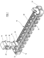
- Fig.1 shows a connector 10 having a base 12 onto which, in the first position of the base 12 a first plug 14 is mounted.
- a second plug 16 is shown which is intended to be mounted on top of the first plug 14.
- the second plug 16 is covered with a protective cap 18.
- the base 12 has an elongated configuration with a multiplicity of positions that allow the mounting of the plugs. Walls are formed in the body of the base giving a configuration 20 with U-shaped walls corresponding to the inner part of the end portion of the insulating body of the first plug 14 which faces the base.
- the configuration 20, together with the projecting adjacent configuration 22, ensures that in conjunction with the formation of the corresponding end portion of the first plug 14 the plug itself can easily be mounted onto the base.
- the second plug 16 is shown in a position immediately prior to its mounting onto the first plug 14.
- the plugs have apertures 24, 26, 28 and 30 respectively into which the wires of the wire pairs (not shown) will be inserted (this will be referred to in more detail in connection with the description of Fig. 12).
- Base 12 is preferably moulded using known molding techniques as a single piece and has an elongated configuration as shown with latches 32 which allow the mounting of the entire base onto a support frame. These latches 32 have the form of curved arms leaving a free space between them and the adjacent side wall. With these provisions the entire base 12 can be mounted on e.g., two bars of a support frame (not shown). Another solution for the mounting of base 12 will be referred to in connection with Fig. 5.
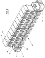
- Fig. 2 shows a connector 10 with the base 12 onto which first plugs 14 and second plugs 16 provided with protective caps 18 are mounted onto every position of the base.
- the apertures 24, 26, 28, and 30 of all plugs will typically be provided, and connected, with pairs of wires.
- the connector according to Fig. 2 would be connected to ten pairs of feeder wires mounted onto the first plugs 14, while the second plugs 16 will be connected with up to ten pairs of jumper wires. These wires are left out for the sake of simplicity and are only shown in Fig. 12.
- Fig. 2 The configuration as shown in Fig. 2 will be the standard one filling all positions with pairs of plugs. However, the system would also allow a whole variety of other configurations, some of them being shown in Fig. 3.
- Base 12 is provided with plug assemblies on each of the three positions, 34, 36 and 38 respectively.
- On position 34 which is actually the fourth one in the base 12 a configuration is shown which is considered to be the normal one as already depicted in Figure 2.
- a first plug 14 is mounted onto the base 12.
- a second plug 16 with a protective cap 18 is mounted on top of this, and under normal conditions, wires are inserted into the apertures 24, 26, 28, and 30, and connected to the plugs.
- a short wire pair is connected at both ends to a plug to obtain a configuration similar to an extension cord, however, with a pair of equal plugs. Then the assembly of plug 14 and plug 16 are jointly removed from the base 12. Furthermore, cap 18 is removed from plug 16. Plugs 14 and 16 (without being disconnected) are mounted onto one of the pair of plugs which have been connected with the short wire pair. The second plug of the pair is mounted on top of plug 16, so that a pile of four plugs is obtained, being separated from base 12 and for example, held by hand. Then this pile of four plugs is separated in the middle, so that plug 14 is placed on one of the pair of plugs and 16 on the other one, both of them still being connected with the short wire pair. Accordingly, the circuitry is not disconnected.
- plug 16 and the additional plug on top of it are placed onto plug 46, after the removal of the corresponding cap 18, so that at position 38, a pile of three plugs is obtained.
- the jumper wires of plug 16 are connected to both of the feeder wires of plug 14 as well as of the feeder wires of plug 46.
- the plug on top of the stack of the three plugs in position 38 is removed and the cap 18 is attached. Now only a connection is left between the feeder wires of plug 46 and the jumper wires of plug 16.
- Plug 14, then for example, is removed from the other plug of the pair and is placed back in its original position and covered with the left over cap 18, so that at the end the pair of plugs connected to each other with a wire pair are available for other similar operations.
- Fig. 4 shows an alternative configuration for the base.
- the base is supposed to be fitted with a number of plugs for the establishment of, e.g., 10 connections.
- Other counts can be thought of as e.g., 5 or 20, or under very specific circumstances, just a single count.
- FIG. 4 This is depicted in detail in Fig. 4 where the base 48 has just a single position without any means for the attachment to a support frame.
- a first plug 50 is mounted onto the base 48 and a second plug 52 covered with a protective cap 54 is mounted onto the first plug 50.
- the simple advantage of this approach can be, that under some circumstances it is necessary to establish a connection between two wire pairs only, independent from the arrangement of other wire pairs. Then this could be established according to the system shown in Fig. 4. It allows the use of the same type of plugs for this individual connection by simply utilising a specific shortened version of the base, namely the configuration 48. With the existing systems, a separate and differently designed connector for two wire pairs would be necessary.
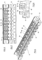
- Figs. 5 through 8 show the base, 12, in more detail.
- This base 12 is a single piece component typically obtained through a moulding process. It has specific configurations at ten different positions, allowing the mounting of up to ten plugs 14.
- an essentially rectangular arrangement can be seen onto which an additional part 22 is projecting therefrom.
- the rectangular configuration consists of essentially two distinctive arrays of U-shaped walls 56 and 58 where, between them, a slot 60 is left on both sides.
- the projecting portions 22 are connected to the rectangular configuration 20 through bridge portion 62.
- a continuous wall 64 is arranged behind the rectangular wall configurations 20.
- Fig. 6 shows the view from the top - the side onto which the plugs are mounted -
- Fig. 7 shows the bottom configuration.
- FIG. 8 shows a cross-sectional view along the line A-A of Fig. 6.
- This cross-sectional view demonstrates that the base has a ground plate, 66, which is extending throughout the entire base, except for the front portions 22.
- the rectangular configurations 20 with the details 56, 58 and 60 are projecting from this base plate and allow the mounting of the plugs with the corresponding internal configurations at their end portions facing the base.
- Below the base plate 66 a free space 68 is left to obtain sufficient stability of the base by simultanously maintaining a more or less constant thickness of all walls which is necessary to facilitate a moulding process.
- a cavity 70 is left filled with grease (e.g., EG3 supplied by the Minnesota Mining & Manufacturing Company).
- Figs. 5, 6, and 7, which differ from those shown in Figs. 1, 2 and 3.
- openings are shown in the form of a slot with a semi-cylindric end portion, which can be used in order to screw the base onto a support frame of some type.
- Fig. 9 shows a portion of base 12 where the end projections 22 are formed in such a way that wire holding or guidance features are obtained.
- the front portions which may have different shapes, are leaving only relatively narrow slots 74 through which individual wires can be passed. These wires are captured in the space between two adjacent projections 22.
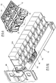
- Fig. 10 shows another embodiment of the base 12 where the wall 64 has an embedded grounding bar 76 from which, at every position of the base 12, a prong 78 is projecting. These prongs are supposed to interact with a plug having over-voltage protection, which will be discussed in more detail in connection with Fig. 14.
- Bar 76 is mechanically and electrically connected to another bar 80 which is connected to ground and is in a perpendicular arrangement with respect to the base 12. With this configuration the gound connection to protected plugs can be achieved.
- Fig. 11 shows a plug 82 (corresponding to plugs 14, 16, 40. 42. 44. 46. 50, 52 in Fig. 1 - 4) from the outside.
- the plug is seen in a perspective view from the end portion of the insulating body of the plug, which directly or indirectly faces the base 12. It shows the end portions 84 and 86 of the metal contact elements projecting from the insulating body of the plug 82. On the upper side the apertures 88 and 90 for the insertion of the wire can be seen.
- the end portion of plug 82 has walls forming an essentially rectangular configuration.
- the inner portions 92 and 94 of which, together with the longitudinal protrusion 96, match the corresponding configurations on the base 12 of Figs. 5 and 6, having the configurations 56 and 58 and the slot 60.
- This design allows another plug to engage with plug 82 so that the inner portions 92 and 94, and the longitudinal protrusion 96 of the second plug, would engage with the outer portions of the walls 98 and 100 and the slot 102 of the first plug, thus rendering the plugs stackable on top of each other (the fork portions 84 and 86 of the contact elements of one plug will engage with the corresponding portions of the other plug, which will be referred to in Figs. 15 and 16.
- the tolerances for formations 56, 58 and 60 on the base 12 and 92, 94, 96, 98, 100 and 102 on the plugs are chosen so that the force to remove a plug 16 from another plug 14 is smaller than the force necessary for the removal of a plug 14 from the base 12.
- Fig. 12 shows the plug 82 in a perspective manner from the top.
- the fork portion 84 of the end of the contact element can be slightly seen.
- the apertures 88 and 90 for the insertion of the wires of the wire pair, as well as the above described rectangular configurations 98 and 100 and the slot in between them 102 can be seen, all of them belonging to a hinged cap 104.
- Configuration 98 has a rectangular opening and in the bottom two slots (not shown) allowing the insertion of fork portions 84 and 86 when mounting another plug onto plug 82.
- Cap 104 is rotated around the axis 106 and can be removed from the main body of the plug 82 typically through the use of a simple hand tool.
- the hinged cap 104 is held in place through the protruding portion 108 onto which the hinged cap 104 is snapped on.
- the tool allows the movement of the end of the hinged cap 104 over these protruded portions.
- Inside the body of the plug 82 the upper portions of the contact elements can be seen, having the form of insulation displacing contact portions 110 and 112.
- the two wires 114 and 116 of the wire pair are inserted into the apertures 88 and 90.
- the hinged cap 104 is moved back into its original position until it snaps over the protruded portion 108. With this movement the insulation displacement portions 110 and 112 of the metal contact elements, penetrate through the insulation of the wires 114 and 116 thus establishing a permanent contact in a well-known manner. This can typically be done manually. It may eventually be necessary to place the protective cap 18 (not shown) over the upper portion of the hinged cap which then covers the wall configuration 98 and 100 and the slot 102. On the side of plug 82 a slotted portion 118 of a metal component can be seen which will be explained in connection with Fig. 14.
- Fig. 13 can be best understood in conjunction with Figs. 11 and 12, which specifically show that the metal contact element consists of a tuning forked-type portion 84 projecting from the end of the plug, and an upper portion 110 which has the form of an insulation displacement element. It can be seen that the two portions of the contact element are rotated with respect to each other at an angle of 90°. Furthermore, opening 105 can be seen so that plug 82 can receive the projecting contact portions of another plug mounted on top of plug 82. Finally, it can be seen that the plug 82 essentially is made up of four components, namely a lower part of the insulative body 120 plus an upper part of the insulative body 122 and the two contact elements, one of them 124 being visable in this cross-sectional view.
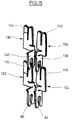
- Fig. 14 shows a specific configuration for the electrical protection of the plug.
- the metal contact elements 124 are shown with their insulation displacement contact portions 84, 86 and tuning fork portions 110, 112.
- An additional metal strip is integrally connected to the insulation displacement contact portion 84, 86 and bent over at an angle of 90°. Directly connected are voltage-limiting elements 126, 128.
- Fig. 14 shows the configuration in an exploded view between the two metal contact elements 124.
- a ground contact is arranged having an external contact portion 118 which also is visible on Fig. 12 being in line with the outer wall of plug 82.
- This external contact is integrally connected to two plates 130, which are formed as shown. After the assembly, plates 130 get in direct contact with the voltage-limiting elements 126, 128. The over-voltage protection is achieved when inserting a plug with this configuration into the base 12, the principle being visible in figure 10.
- the outer contact 118 engages with prongs 78 of bar 76 which, through the second bar 80, is connected to ground level. Accordingly, plugs which are inserted on the base 12 of Fig. 10 are grounded in contact portions 118 and 130 so that the over-voltage protection is operational.
- Fig. 15 more distinctively shows in which way the metal contact elements of two adjacent plugs engage with each other.
- the contact elements 124 and 132 can e.g., be considered as the contact elements belonging to a first plug 14 to be mounted onto the base 12. They have the tuning fork portion 84 and 86, and the insulation displacement contact portions 110 and 112. As explained above, wires 114 and 116 are moved during the connection into the slots of the insulation displacement contact portions 110 and 112. When placing the first plug onto the base, the projecting tuning fork portions 84 and 86 move into the cavities 70 (see Fig. 5), which provide the necessary protection (it is favourable to fill this cavity 70 with grease).
- Figs. 1 through 4 operate.
- This can be seen when taking a cross-sectional view through the base, a first plug and a second plug, at the location of the tuning fork portions 84 or 86 of the contact elements 124 or 132.
- This is shown in Fig. 16, showing the base 12 a first plug 14 a second plug 16 and a protective cover 18.
- the fork portion 84 of plug 14 is entering the cavity 70 which, in portion 146, is filled with grease.
- This cross-sectional view can be best understood when comparing it in detail with the figures 5, 6, 11, 13, and 15 in which the same designations have been used.
Abstract
Description
- The invention relates to an electrical connector for the connection of at least one set of wire pairs to be connected to each other. This is of particular interest in the field of telecommunication distribution networks. The connection, or splicing, of pairs of electrical wires is more specifically of interest in the so-called cross connect systems, where wire pairs arriving from a central office, have to be distributed to the end users in an efficient manner. Typically, two pairs of wires have to be connected to each other by means that, at a later point in time, allow the modification of the connections without destroying the connectors. Furthermore, to a growing extent, connections have to be made to at least a third pair of wires for testing, half-tapping, or transfers without the interruption of the circuits.
- Telecommunication distribution systems, by their nature, involve a high number of wire pairs to be connected. Over a long period of time, it was common to use terminal blocks, or modules, into which a multiplicity of wire pairs is inserted, which then have to be connected to a second multiplicity of pairs of corresponding wires. This is described in a number of references, such as the US Patents 3,919,495, 4,685,755, 4,964,812, 5,044,979 and 5,147,218. These terminal blocks, or modules, are used for the permanent connection of wire pairs, and do not allow the modification of the connections in a simple manner. Some of the modules are primarily used for the connection of telecommunication cables with a high number of wire pairs. Others are more specifically designed for cross connect systems. However, in these references changes are difficult to achieve. They would require the cutting off of the individual wire pairs, and connecting them to their corresponding pairs, by separate means, e.g., through the use of specific small connectors for the connection of two pairs of wires.
- A typical cross connect system receives a multiplicity of wire pairs from, e.g., a central office, and another multiplicity of wire pairs arriving from the end users, or some other intermediate distribution unit. For the establishment of the connections, so-called feeder wires are inserted into the base of an elongate connector that has a base in the form of a terminal block and that can receive a multiplicity of wire pairs (e.g. ten pairs). A permanent connection of these feeder wires is achieved by some means, either through a simple tool, or by an additional component of the connector, which is pressed onto the base, thus establishing the contacts for which, typically, insulation displacement metal elements are used. This is done, both for the incoming multiplicity of wires coming from the central office, as well as that coming from either the end users or some other intermediate distribution unit. Subsequently, individual connections are made between the terminal block with the wire pairs coming from the central office, and the second terminal block with the wire pairs coming from the end users or the intermediate distribution units. This is achieved through so-called jumper wires. A preferred approach is to connect a pair of jumper wires to plugs at both ends and to mount these plugs onto the corresponding positions in the terminal blocks, onto which the feeder wires are permanently connected. This is commonly done and described in a number of references, such as the following patents or patent applications: US 4,979,209, EP 0 084 632, EP 0 220 884, and GB 2 129 630.
Furthermore, the European Patent Application, EP 0 261 332, describes a base configuration for a cross connect system which, only includes a multiplicity of terminal blocks. Another approach can be seen from the German patents, DE 41 27 896,DE 40 08 386, andDE 40 08 388 where the feeder wires are inserted into the base through the use of a simple hand tool. The connection is again achieved by the use of plugs. - Generally speaking, plugs referred to in the above cited documents are designed, so that the wire pairs can be connected to them by simple means, typically using contact elements, which have an insulation displacement feature. The connection of the wires to the plugs can be made either manually, or through the use of a simple hand tool. Typically,besides the insulation displacement portion, the contact elements have a second portion, which is designed in such a manner, that it allows a mounting onto the terminal block onto which the feeder wires are permanently connected. In some instances, as described in EP 0 220 884, it is possible to access the plug with a test probe.
More generally, the plugs have at least an insulative body and metal contact elements, which are supported in the body. The contact elements have a portion for the connection to typically one wire pair, and another portion for the connection to another contact element located in another component of the connector for the connection to another wire pair. - However, the above described references do not yield the possibility of attaching a second plug onto the first one, which to a growing extent is desirable in order to allow the so-called half-tapping, or a more permanent testing, or a modification of the connection, without any interruption. Therefore, there is an increasing need not only to connect two pairs of wires to each other, but to make an additional connection to a third pair, e.g., for an additional telephone set (so-called half-tapping) or with the increased use of data transfer communication to achieve modifications without the interruption of the circuit. This can be done when using systems according to the patents US 5,178,558 and 5,281,163. Here, cross connect systems are described in which a base with a terminal block is used, as described above, onto which the feeder wires are permanently connected and where plugs are used which can be stacked on top of each other to provide the above mentioned special features. This terminal block can also be considered as a base that is capable of supporting other components of the connector.
- The above described systems, having a terminal block and plugs that can be stacked on top of each other, readily provide a high level of flexiblitiy with respect to the achievement of modifications in a cross-connect system. However, the use of terminal blocks includes the insertion of the multiplicity of wire pairs, as described above, into the terminal block, with a subsequent connection of the wires to the corresponding contact elements. This requires an expensive and cumbersome tool which, due to the high crimping forces, is either pneumatically driven or externally powered. This significantly reduces the flexibility and versatility of the system. Accordingly, it is the object of the invention to provide a connector for the connection of at least one set of wire pairs to be connected to each other, which provides a higher degree of flexibility with respect to circuit modifications and, in particular, does not require the use of complex and expensive tools.
- The present invention provides an electrical connector for the connection of at least one set of wire pairs to be connected to each other and offers a solution to the above mentioned problem according to the characterising part of Claim 1.
- The essence of the invention is that the terminal block for a permanent connection of wires and in particular feeder wire pairs, is replaced by a base which is provided with means for the releasable mounting and supporting of at least one plug. On this base a first plug for a first wire pair of the set of wire pairs is mounted, and at least a second plug for a second wire pair of the set of wire pairs, is releasably mounted onto the first plug. The contact elements within the at least two plugs are being formed and arranged within their respective bodies, so that an electrical contact is established between the wires of the first wire pair and the respective wires of the second wire pair, when mounting the second plug onto the first plug. The wires of the wire pairs can easily be connected to the respective plugs in a known manner. This is typically achieved either manually, or through the use of a simple hand tool. While the terminal blocks of the known solutions always include means for the permanent connection of wires, the base according to the invention has the primary purpose to support at least one pair of plugs which are mounted on top of each other. The basic advantage of using a relatively simple base onto which plugs are mounted is that, unlike with terminal blocks, no sophisticated and expensive tool is needed for the assembly. Furthermore, the connections can no longer be considered to be permanent with respect to the feeder wires. The fact that the first plug is releasably mounted onto the base, leads to an unexpected variety of features which so far have not been available through the use of terminal blocks. This will be explained in more detail below.
As mentioned above in this invention a plug is defined in a more general sense, namely having an insulative body and contact elements supported in the body, whereby these contact elements have a first portion for the connection to the respective wire pair and a second portion for the connection to another contact element which is located in another component of the connector, typically another plug. This means that a plug according to this definition can also be a receptacle. The first plugs which are mounted onto the base, have to provide means for the connection of the respective wire pair and other means that allow to mount a second plug onto the first one which, therefore, has the typical function of a receptacle. - In the most general sense the base needs only to have a single position for the mounting of a first plug onto which a second plug is mounted. This, however, is not the preferred embodiment for a cross connect system. However, such a configuration with a single position base and at least two plugs mounted thereon, can be a helpful addition to the typical cross connect system. In some instances, there may be the need to connect two wire pairs to each other which for some reason would have to be separated from the typical arrangement of e.g., ten wire pairs in a module. This may be advantagous under specific circumstances, such as the case that the corresponding wire pairs are too short to be guided to their respective modules or that an intermediate non-permanent connection has to be established.
- The typical configuration however, is a base which is elongated and which at a multiplicity of positions which are adjacent to each other, is provided with means for supporting a multiplicity of plugs. In a situation in which a high number of wire pairs have to be connected to each other, all the positions of the base are used with typically a first plug and a second plug in every position. For example, the most common case is to use bases that have ten positions onto which then ten first plugs are mounted, connected to ten pairs of feeder wires. Subsequently, a set of ten second plugs which are connected to ten pairs of jumper wires are mounted onto the first plugs. The system however, also allows a large variety of other configurations. It might be advantagous and desirable to only place plugs onto a fraction of the multiplicity of the positions in the base. This can be desirable if the option should be kept open to leave space for the future addition of the feeder wire pairs.
- Normally, as described above, plugs are placed in pairs onto the base, however, for a number of reasons it is possible to add other plugs on top of the pairs of plugs. This may be needed for the so called half-tapping in which an additional connection is made to a second telephone set. Another possibility is that for whatever reason, it may be desirable over a longer period of time to have a more permanent connection to a testing device.
- It may also be desirable at some positions in the base to mount only a single plug onto which a pair of feeder wires is connected. This may be of interest if, for some reason, a pair of feeder wires coming from the central office is already in place without the need to establish a connection to an end user. In this case the wire pair is in a defined position and the connection can easily be made at a later point in time.
- It is further advantagous to place a protective cover over the uppermost plugs mounted onto the base. This is well known and also applicable to the system according to the invention
- As described above, the first plug may have the form of a receptacle onto which a second plug is placed. However, it is more advantagous to use only one type of plugs. In this case, the plugs preferably should be designed so that the contact elements with their second portions are projecting from the portion of the insulating body of the plug, which directly, or indirectly faces the base. The opposite end portion of the insulating body is provided with openings so that it allows the reception of the corresponding projecting contact element portions of another plug. Furthermore, the means in the base for the supporting of the plug, are provided with a cavity into which, upon the mounting of the plug onto the base, the projecting ends of the contact element enters. For various reasons,, these cavities are filled with a sealant. This sealant can be a grease, a gel, or the like, e.g., a two component silicone composition. The use of sealants is well known and also applicable to the connector according to the invention. It provides a protection to the projecting second portions of the contact elements, so upon a later removal of the first plug from the base, contacts to other plugs can easily be established. This is of significance as the system offers to take a first plug originally fitted with feeder wires and mount it on top of any other plug located on the same or another base. This shows that an excessive number of variations is possible with this modular system (some specific examples will be given below).
- For some reason it is advantagous that the array of first plugs on the base, should also be treated in the conventional manner namely as a terminal block. Here, as mentioned above the advantage of avoiding the use of a complex tool is still valid. However, it might be desirable to have the first plugs in a fairly stable position, so that second plugs can be removed from the first plugs without removing the first plugs from the base. This can be achieved by chosing the tolerances of the means in the base, and the tolerances in the insulative bodies of the plugs, so that the force needed to remove a second plug from a first plug is smaller than the force needed to remove the first plug from the base. This is in line with the typical requirements for tolerances and, therefore, can be achieved without any additional cost.
- As explained above, plugs have been defined in a relatively general manner, namely having means for the connection of a wire pair and portions of the contact element which can engage with other contact elements in other components of the connector. The connection of the wires onto the first portions of the contact elements can be established through a variety of means, such as the use of minature screws, crimping, wire wrapping, miniature flame soldering. The most preferred approach, however, is the use of insulation displacement features where the insulation of the wires is displaced during its insertion into the plug. Insulation displacement features are also known in a large variety. Metal elements with teeth can be pushed onto the wires thus penetrating the insulation or pins would be pushed through the insulation. In the most preferred and most common case, so called U-elements are used, which are simple metal plates provided with a slot with two sides of the slot designed so that, upon the insertion, these two sides are slightly deflected establishing a permanent contact.
- The second portion of the contact elements in the plug is supposed to establish a contact with another contact element in another component of the connector. This also can be shaped in a large variety of manners. For instance, it is possible to give the second portions of the contact elements, the form of a pin and the corresponding portion in the other component of the connector the form of the receptacle in the form of a cylinder into which the pin can be inserted. Another possibility would be to use bendable end portions which slide onto corresponding flat areas in the other contact element located in the other component of the connector. The more preferred approach is to give the second portion of the contact element the form of a tuning fork which, upon insertion, engages with the side portion of the respective insulation displacing contact element in the other component. The advantage of this approach is that through this means the contact elements are given a particularly simple design which is advantagous with respect to the manufacturing cost.
- In another preferred embodiment of the invention, the plugs are provided with a hinged cap which is supported on one end and which can be opened for the insertion of the respective wires. These wires are placed into apertures and the upper portions of the contact elements have insulation displacing features. These contact elements are arranged with respect to the hinged cap so that upon closing the cap onto the plug, the electrical contact between the inserted wires, and the insulation displacing contact portion is effected (further details of this approach can be taken from the patent US 5,178,558).
- Frequently, it is desirable to provide means for the over-voltage protection of the system. This is well known and for example described in the patent US 5,281,163. This system is also applicable to the present invention. In this case, at least the first plugs are provided with means for an electrical protection. These can, for example, be voltage limiting elements, such as diac or trigger diodes, which are normally insulative but short across if the voltage exceeds a predetermined amount such as 270 volts. These means for the over-voltage protection are on one side connected to the contact elements, and on the other side to an externally accessible contact element which is arranged in the outer portion of the insulative body of the plug. Furthermore, the base can be directly or indirectly provided with a grounding element which is electrically connected to ground and onto which upon the mounting of the plug, an electrical contact is established between the externally accessible contact elements of the plug and the grounding element which, for instance, can have the form of a bar which is provided with a multiplicity of prongs into which the above mentioned externally accessible contact elements of the plug interract. The grounding of these bars is then achieved in the usual manner.
- Similar to the known terminal blocks, also the base can be provided with means that allow the attachment of it to a support frame. Most preferably, for elongated bases these means are arranged at the ends of the base which then is mounted in the same manner as known terminal blocks.
- Finally it is advantageous to provide the front portion of the base with means for the guidance and the fixing of the wire pairs. Some formations could be applied to the longitudinal side of the base to which the wire pairs have to be guided to. These formations can be hooks or small slots between adjacent projecting portions. The wires can then be brought into the corresponding free spaces in which they are held in place. This avoids an uncontrollable disarray of all the wire pairs.
- The invention will be more fully understood with reference to the accompanying drawings, wherein
- Fig. 1
- is a perspective view of the connector including the base, a first plug and a second plug;
- Fig. 2
- is a perspective view of the connector having the first and the second plugs mounted onto every position of the base;
- Fig. 3
- is a perspective view of the connector with the base fitted with a varying number of plugs at only three positions;
- Fig. 4
- is a perspective view of a connector with a base having only a single position onto which a first and a second plug are mounted;
- Fig. 5
- being a perspective view of the base only;
- Fig. 6
- giving a view from the top onto the base;
- Fig. 7
- giving a view from the bottom onto the base;
- Fig. 8
- giving a side cross-sectional view through the base at the location marked with A-A in Fig 6;
- Fig. 9
- showing a portion of the base provided with wire holding and guiding means;
- Fig. 10
- showing another embodiment of the base fitted with plugs and provided with a grounding bar for the overvoltage protection of the plugs.
- Fig. 11
- giving a perspective view of a single plug viewing at the end portion of the insulating body which directly or indirectly is facing the base;
- Fig. 12
- giving a perspective view of the plug viewed from the opposite end portion with the hinged cap opened;
- Fig. 13
- giving a cross-sectional view through the plug;
- Fig. 14
- giving a perspective and exploded view on a pair of contact elements with additional elements providing electrical protection.
- Fig. 15
- giving a perspective view of two sets of metal contact elements of the first and second plug; and
- Fig. 16
- giving a cross-sectional view through the connector at the plane of the fork portion of contact elements showing the base, a first plug, a second plug, and a protective cover.
- The essentials of the invention are depicted in Figs. 1 through 8, and Fig. 16, while further details of the plugs are shown in Figs. 9 through 15. Details of the plugs are only referred to whenever necessary in view of this invention. Further aspects related to the plugs can be taken from the patents US 5,178,558 and US 5,281,163.
- Fig.1 shows a
connector 10 having a base 12 onto which, in the first position of the base 12 afirst plug 14 is mounted. Asecond plug 16 is shown which is intended to be mounted on top of thefirst plug 14. Thesecond plug 16 is covered with aprotective cap 18. Thebase 12 has an elongated configuration with a multiplicity of positions that allow the mounting of the plugs. Walls are formed in the body of the base giving aconfiguration 20 with U-shaped walls corresponding to the inner part of the end portion of the insulating body of thefirst plug 14 which faces the base. Theconfiguration 20, together with the projectingadjacent configuration 22, ensures that in conjunction with the formation of the corresponding end portion of thefirst plug 14 the plug itself can easily be mounted onto the base. This does not require an undue force and can typically be done by hand. An additional tool is not necessary. Thesecond plug 16 is shown in a position immediately prior to its mounting onto thefirst plug 14. The plugs haveapertures Base 12 is preferably moulded using known molding techniques as a single piece and has an elongated configuration as shown withlatches 32 which allow the mounting of the entire base onto a support frame. These latches 32 have the form of curved arms leaving a free space between them and the adjacent side wall. With these provisions theentire base 12 can be mounted on e.g., two bars of a support frame (not shown). Another solution for the mounting ofbase 12 will be referred to in connection with Fig. 5. - Fig. 2 shows a
connector 10 with the base 12 onto which first plugs 14 andsecond plugs 16 provided withprotective caps 18 are mounted onto every position of the base. In practical applications, theapertures - The configuration as shown in Fig. 2 will be the standard one filling all positions with pairs of plugs. However, the system would also allow a whole variety of other configurations, some of them being shown in Fig. 3.
Base 12 is provided with plug assemblies on each of the three positions, 34, 36 and 38 respectively. Onposition 34 which is actually the fourth one in the base 12 a configuration is shown which is considered to be the normal one as already depicted in Figure 2. Afirst plug 14 is mounted onto thebase 12. Asecond plug 16 with aprotective cap 18 is mounted on top of this, and under normal conditions, wires are inserted into theapertures first plug 14 in theapertures second plug 16 through theapertures 28 and 30 (see Fig. 2). Inposition 36, which is the seventh position on the base 12 threeplugs third plug 44 which, after removal ofcap 18 is mounted ontoplug 42. Finally cap 18 is placed ontoplug 44. As another example, a single plug is mounted onto thefirst position 38 of thebase 12. This may be of importance for some applications in which a connection between two or more pairs of wires is only desired at a later point in time. It may eventually be advisable to only establish a connection to the connector from the central office, which means that the corresponding wire pair is connected onto theplug 46 so that at any later date it would be possible to mount a second (or eventually an additional third) plug ontoplug 46 to finally establish a desired connection. - For such a connection at a later point in time, for example, the necessity may come up to remove the jumper pair at
plug 16 from the feeder wire pair inplug 14, and establish a connection with the feeder pair inplug 46. The most simple approach would be to removecap 18 from the top ofplug 46 and removeplug 16 fromplug 14 and mount it directly together with itscorresponding cap 18 ontoplug 46. The remainingcap 18 can then be placed on top ofplug 14. In this case, an exchange betweenposition plug 14 would be without any connection. - It would also be possible to modify the connection without an interruption of the circuit, which is particularly desirable if the related circuitry belongs to a data transmission line. In this case the following approach could be taken (not shown in the figures): A short wire pair is connected at both ends to a plug to obtain a configuration similar to an extension cord, however, with a pair of equal plugs. Then the assembly of
plug 14 and plug 16 are jointly removed from thebase 12. Furthermore,cap 18 is removed fromplug 16.Plugs 14 and 16 (without being disconnected) are mounted onto one of the pair of plugs which have been connected with the short wire pair. The second plug of the pair is mounted on top ofplug 16, so that a pile of four plugs is obtained, being separated frombase 12 and for example, held by hand. Then this pile of four plugs is separated in the middle, so thatplug 14 is placed on one of the pair of plugs and 16 on the other one, both of them still being connected with the short wire pair. Accordingly, the circuitry is not disconnected. - Subsequently, plug 16 and the additional plug on top of it, are placed onto
plug 46, after the removal of thecorresponding cap 18, so that atposition 38, a pile of three plugs is obtained. Now, the jumper wires ofplug 16 are connected to both of the feeder wires ofplug 14 as well as of the feeder wires ofplug 46. Finally, the plug on top of the stack of the three plugs inposition 38 is removed and thecap 18 is attached. Now only a connection is left between the feeder wires ofplug 46 and the jumper wires ofplug 16.Plug 14, then for example, is removed from the other plug of the pair and is placed back in its original position and covered with the left overcap 18, so that at the end the pair of plugs connected to each other with a wire pair are available for other similar operations. - Another alternative to change connections without circuit interruption is the following: As before, the pile of four plugs held by hand is created. Then they are also separated in the middle. Subsequently a fifth plug is mounted onto
plug 14, this plug being connected with a wire pair belonging to a new end user. Then the plug belowplug 14 is removed and the remaining pair consisting ofplug 14 and the fifth plug are mounted onto a new position onbase 12. Finally, acap 18 is placed onto the fifth plug. The old distribution withplug 16 can e.g., be placed back toposition 34. Now the feeder wire pair onplug 14 is connected to a new user line and a circuit interruption has been avoided. - Similar approaches are shown in the patent US 5,178,558 Fig. 11. The basic difference is that the feeder wires are no longer permanently installed. The following configuration would not be possible with the system described in patent US 5,178,558, the above described procedure would also be possible when starting with the connection on
position 34 only, and establishing a completely new connection of feeder wires toposition 38. These examples demonstrate the versatility of the system. - Fig. 4 shows an alternative configuration for the base. Typically the base is supposed to be fitted with a number of plugs for the establishment of, e.g., 10 connections. Other counts can be thought of as e.g., 5 or 20, or under very specific circumstances, just a single count.
- This is depicted in detail in Fig. 4 where the
base 48 has just a single position without any means for the attachment to a support frame. Afirst plug 50 is mounted onto thebase 48 and asecond plug 52 covered with aprotective cap 54 is mounted onto thefirst plug 50. This allows a connection to be made between just two pairs of wires. The simple advantage of this approach can be, that under some circumstances it is necessary to establish a connection between two wire pairs only, independent from the arrangement of other wire pairs. Then this could be established according to the system shown in Fig. 4. It allows the use of the same type of plugs for this individual connection by simply utilising a specific shortened version of the base, namely theconfiguration 48. With the existing systems, a separate and differently designed connector for two wire pairs would be necessary. - Figs. 5 through 8 show the base, 12, in more detail. This
base 12 is a single piece component typically obtained through a moulding process. It has specific configurations at ten different positions, allowing the mounting of up to ten plugs 14. In theconfiguration 20, an essentially rectangular arrangement can be seen onto which anadditional part 22 is projecting therefrom. The rectangular configuration consists of essentially two distinctive arrays ofU-shaped walls slot 60 is left on both sides. The projectingportions 22 are connected to therectangular configuration 20 throughbridge portion 62. Acontinuous wall 64 is arranged behind therectangular wall configurations 20. Fig. 6 shows the view from the top - the side onto which the plugs are mounted - Fig. 7 shows the bottom configuration. Fig. 8 shows a cross-sectional view along the line A-A of Fig. 6. This cross-sectional view demonstrates that the base has a ground plate, 66, which is extending throughout the entire base, except for thefront portions 22. Therectangular configurations 20 with thedetails free space 68 is left to obtain sufficient stability of the base by simultanously maintaining a more or less constant thickness of all walls which is necessary to facilitate a moulding process. Furthermore, in the configurations 58 acavity 70 is left filled with grease (e.g., EG3 supplied by the Minnesota Mining & Manufacturing Company). This will be referred to below (see Fig. 16). Finally, means for the mounting of the base 12 are shown in Figs. 5, 6, and 7, which differ from those shown in Figs. 1, 2 and 3. In this case, openings are shown in the form of a slot with a semi-cylindric end portion, which can be used in order to screw the base onto a support frame of some type. - Fig. 9 shows a portion of
base 12 where theend projections 22 are formed in such a way that wire holding or guidance features are obtained. The front portions, which may have different shapes, are leaving only relativelynarrow slots 74 through which individual wires can be passed. These wires are captured in the space between twoadjacent projections 22. - Fig. 10 shows another embodiment of the base 12 where the
wall 64 has an embeddedgrounding bar 76 from which, at every position of thebase 12, aprong 78 is projecting. These prongs are supposed to interact with a plug having over-voltage protection, which will be discussed in more detail in connection with Fig. 14.Bar 76 is mechanically and electrically connected to anotherbar 80 which is connected to ground and is in a perpendicular arrangement with respect to thebase 12. With this configuration the gound connection to protected plugs can be achieved. - Fig. 11 shows a plug 82 (corresponding to
plugs base 12. It shows theend portions plug 82. On the upper side theapertures plug 82 has walls forming an essentially rectangular configuration. Theinner portions longitudinal protrusion 96, match the corresponding configurations on thebase 12 of Figs. 5 and 6, having theconfigurations slot 60. When mounting theplug 82 onto the base 12 the inner portions of the walls of theplug 82 indicated with 92 and 94 engage with the external portions of thewalls base 12, while thelongitudinal protrusion 96 of theplug 82 passes into theslot 60 of thebase 12. On the upperside of theplug 82, as shown in Fig. 11,configurations rectangular configuration 98 and anothersimilar configuration 100 adjacent to it, having theslot 102 between them. This design allows another plug to engage withplug 82 so that theinner portions longitudinal protrusion 96 of the second plug, would engage with the outer portions of thewalls slot 102 of the first plug, thus rendering the plugs stackable on top of each other (thefork portions formations base plug 16 from anotherplug 14 is smaller than the force necessary for the removal of aplug 14 from thebase 12. - Fig. 12 shows the
plug 82 in a perspective manner from the top. Thefork portion 84 of the end of the contact element can be slightly seen. Theapertures rectangular configurations cap 104.Configuration 98 has a rectangular opening and in the bottom two slots (not shown) allowing the insertion offork portions plug 82.Cap 104 is rotated around theaxis 106 and can be removed from the main body of theplug 82 typically through the use of a simple hand tool. Normally the hingedcap 104 is held in place through the protrudingportion 108 onto which the hingedcap 104 is snapped on. The tool allows the movement of the end of the hingedcap 104 over these protruded portions. Inside the body of theplug 82 the upper portions of the contact elements can be seen, having the form of insulation displacingcontact portions wires apertures - Then the hinged
cap 104 is moved back into its original position until it snaps over the protrudedportion 108. With this movement theinsulation displacement portions wires wall configuration slot 102. On the side of plug 82 a slottedportion 118 of a metal component can be seen which will be explained in connection with Fig. 14. - Fig. 13 can be best understood in conjunction with Figs. 11 and 12, which specifically show that the metal contact element consists of a tuning forked-
type portion 84 projecting from the end of the plug, and anupper portion 110 which has the form of an insulation displacement element. It can be seen that the two portions of the contact element are rotated with respect to each other at an angle of 90°. Furthermore, opening 105 can be seen so thatplug 82 can receive the projecting contact portions of another plug mounted on top ofplug 82. Finally, it can be seen that theplug 82 essentially is made up of four components, namely a lower part of theinsulative body 120 plus an upper part of theinsulative body 122 and the two contact elements, one of them 124 being visable in this cross-sectional view. For the assembly, thecontact elements 124 are placed into the portion of theinsulative body 120 and subsequently, theupper portion 122 is moved over thelower portion 120 until the two parts snap together. This is, however, only of secondary importance in view of this invention.
Fig. 14 shows a specific configuration for the electrical protection of the plug. In this special configuration themetal contact elements 124 are shown with their insulationdisplacement contact portions tuning fork portions displacement contact portion elements metal contact elements 124. A ground contact is arranged having anexternal contact portion 118 which also is visible on Fig. 12 being in line with the outer wall ofplug 82. This external contact is integrally connected to twoplates 130, which are formed as shown. After the assembly,plates 130 get in direct contact with the voltage-limitingelements base 12, the principle being visible in figure 10. Theouter contact 118 engages withprongs 78 ofbar 76 which, through thesecond bar 80, is connected to ground level. Accordingly, plugs which are inserted on thebase 12 of Fig. 10 are grounded incontact portions - Fig. 15 more distinctively shows in which way the metal contact elements of two adjacent plugs engage with each other. The
contact elements first plug 14 to be mounted onto thebase 12. They have thetuning fork portion displacement contact portions wires displacement contact portions tuning fork portions cavity 70 with grease). When placing the second plug onto the first plug, withcontact elements tuning fork portions respective opening 105 of the first plug and engage with the side of the insulationdisplacement contact portions tuning fork portions insulation displacement portions contact elements - With these figures in mind, it now can be better understood in which way the configurations shown in Figs. 1 through 4 operate. This can be seen when taking a cross-sectional view through the base, a first plug and a second plug, at the location of the
tuning fork portions contact elements second plug 16 and aprotective cover 18. Thefork portion 84 ofplug 14 is entering thecavity 70 which, inportion 146, is filled with grease. This cross-sectional view can be best understood when comparing it in detail with the figures 5, 6, 11, 13, and 15 in which the same designations have been used.
Claims (15)
- An electrical connector for the connection of at least one set of wire pairs to be connected to each other, comprising- a base having means for supporting other components of the connector, and- plugs for making contact between one pair of the set of wire pairs to at least another pair of the set comprisingcharacterised in that- an insulative body and- metal contact elements supported in the body, each contact element having a first portion for the connection to the respective wire of the one pair of wires, and a second portion for the connection to another contact element located in another component of the connector for the connection to at least, the other pair of wires,- the base (12, 48) is provided with means (20, 22) for releasably mounting and supporting at least one first plug,- the at least one first plug (14, 50) is adapted for the connection of a first wire pair of the set of wire pairs,- at least a second plug (16, 52) for the connection of a second wire pair of the set of wire pairs is releasably mounted onto the first plug (14,50),- the contact elements within the first plug (124, 132) and the contact elements within the second plug (134, 136) are being formed and arranged within the bodies of the plugs (14, 50; 16, 52), for an interengagement of their first and second portions so that an electrical contact is established between the wires of the first wire pair and the respective wires of the second wire pair.
- An electrical connector, according to Claim 1, characterised in that
the base (12) is elongated and at a multiplicity of positions adjacent to each other is provided with means (20, 22) for supporting a multiplicity of plugs (14). - An electrical connector according to Claim 1 or Claim 2 characterised in that
at least in one position of the base (12), at least a third plug (44) is mounted onto the second plug (42). - An electrical connector according to Claim 2 and Claim 3, characterised in that
only a fraction (34, 36, 38) of the multiplicity of positions with means (20, 22) for supporting plugs (14, 40, 46) is used to mount as a stack of at least a first plug (14) and a second plug (16) thereon. - An electrical connector according to Claims 2 to 4, characterised in that
at least in one of the positions (38) of the base (12), being provided with means for the supporting of a plug, a single plug (46) is mounted onto that position in the base (12). - An electrical connector according to any one of Claims 1 to 5, characterised in that
a protective cover (18, 54) is provided to be placed on at least one of the uppermost plugs (16, 44, 46, 52). - An electrical connector, according to any one of Claims 1 to Claim 6, characterised in that- the plugs (14, 16, 50, 52) are identical in shape,- the second contact portions (84, 86; 138, 140) of the contact elements (124, 132; 134, 136) to establish contact with contact elements located in another component of the connector, project beyond the end portion (92, 94, 96) of the insulating body, directly or indirectly facing the base (12), the opposite end portion (98, 100, 102) of the insulating body being provided with openings (105) allowing to receive the projecting contact portions of another plug placed above and- the means (20, 22) in the base (12) for the supporting of the plugs are provided with a cavity (70) that, upon the mounting of the plug (14, 50) onto the base (12), receives the projecting ends of the contacts elements (124, 132).
- An electrical connector, according to Claim 8, characterised in that:
the cavity (70) is filled with a sealant. - An electrical connector, according to any one of Claims 1 to 7, characterised in that
the means (20,22) of the base (12) for the supporting of the plugs (14) and the dimensions of the end portions (92, 94, 96) of the insulating bodies of the plugs (14, 16, 82), designed for their mounting onto the base (12), or the mounting onto another plug are, with respect to their tolerances, chosen in a manner that the force necessary for the removal of a plug (16) from another plug (14) is smaller than the force necessary for the removal of a plug (14) from the base (12). - An electrical connector, according to any one of Claims 1 to 9, characterised in that
the first portions (110, 112; 142, 144) of the metal contact elements (124, 132; 134, 136) of the plugs (14, 16, 40, 42, 44, 46, 50,52, 82) are provided with insulation displacement features for the connection to the respective wires of the pairs. - An electrical connector, according to Claims 10, characterised in that
the second portions (84, 86; 138,140) of the contact elements (124,132; 134,136) in the plugs (14, 16, 40, 42, 46, 50, 52, 82) for the electrical connection with a contact element located in another plug, has the form of a tuning fork, which engages a side portion of the respective insulation displacing contact portion (110,112; 142, 144) of the adjacent plug. - An electrical connector, according to any one of Claim 10 or Claim 11, characterised in that
the plugs (82) are provided with a cap (104) hinged on one end of the insulating body, the cap (104) having means for facilitating connections between the wire pair to be inserted into apertures (88, 90) of the cap (104) and the contact elements (110, 112), the cap (104) being arranged with respect to the insulating displacement contact portions (110, 112) so that, upon closing the hinged cap (104) onto the insulating body of the plug (82), the electrical contact between the inserted wires (114, 116) and the insulation displacing contact portion (110,112) is effected. - An electrical connector, according to any one of claim 1 to 12, characterised in that- at least the first plug (82) is provided with means for an electrical protection (126, 128) connected to an externally accessible contact element (118) arranged in the outer portions of the insulative body of the plug (82) and- a grounding element (76) is integrated into the base (12)or closely arranged thereto, so that upon mounting of the first plug (82) onto the base (12) an electrical contact between the externally accessible contact element (118) of the first plug (82) and the grounding element (76) is established.
- An electrical connector, according to any one of Claims 1 to 13, characterised in that
the base (12) is provided with means (32, 72) allowing to attach the base (12) to a support frame. - An electrical connector, according to Claims 1 to 14, characterised in that
the base (12) is provided with additional means (22, 74) for the guidance of at least a pair of wires to a plug on the base and for fixing of said one pair of wires.
Priority Applications (6)
| Application Number | Priority Date | Filing Date | Title |
|---|---|---|---|
| EP94110302A EP0690523B1 (en) | 1994-07-01 | 1994-07-01 | Modular cross connect system for telecommunication systems |
| ES94110302T ES2121125T3 (en) | 1994-07-01 | 1994-07-01 | MODULAR INTERCONNECTION SYSTEM FOR TELECOMMUNICATION SYSTEMS. |
| DE69413524T DE69413524T2 (en) | 1994-07-01 | 1994-07-01 | Cross-connection system for telecommunication systems |
| TW083106098A TW252232B (en) | 1994-07-01 | 1994-07-04 | Modular cross connect system for telecommunication systems |
| RU95110786/20U RU5048U1 (en) | 1994-07-01 | 1995-06-23 | MODULAR CROSS-LINKING SYSTEM |
| CN95214595U CN2259691Y (en) | 1994-07-01 | 1995-06-24 | Combined cross connector for telecommunication |
Applications Claiming Priority (1)
| Application Number | Priority Date | Filing Date | Title |
|---|---|---|---|
| EP94110302A EP0690523B1 (en) | 1994-07-01 | 1994-07-01 | Modular cross connect system for telecommunication systems |
Publications (2)
| Publication Number | Publication Date |
|---|---|
| EP0690523A1 true EP0690523A1 (en) | 1996-01-03 |
| EP0690523B1 EP0690523B1 (en) | 1998-09-23 |
Family
ID=8216080
Family Applications (1)
| Application Number | Title | Priority Date | Filing Date |
|---|---|---|---|
| EP94110302A Expired - Lifetime EP0690523B1 (en) | 1994-07-01 | 1994-07-01 | Modular cross connect system for telecommunication systems |
Country Status (6)
| Country | Link |
|---|---|
| EP (1) | EP0690523B1 (en) |
| CN (1) | CN2259691Y (en) |
| DE (1) | DE69413524T2 (en) |
| ES (1) | ES2121125T3 (en) |
| RU (1) | RU5048U1 (en) |
| TW (1) | TW252232B (en) |
Cited By (8)
| Publication number | Priority date | Publication date | Assignee | Title |
|---|---|---|---|---|
| DE10232444A1 (en) * | 2002-07-17 | 2004-02-05 | CCS Technology, Inc., Wilmington | Distribution device of a telecommunication system |
| WO2005091440A1 (en) * | 2004-03-12 | 2005-09-29 | Channell Commercial Corporation | Electrical connector |
| EP1764870A1 (en) * | 2005-09-17 | 2007-03-21 | Weidmüller Interface GmbH & Co. KG | Connection system for realising of branchings to continuous conductors |
| FR2900505A1 (en) * | 2006-04-28 | 2007-11-02 | Manuf D App Electr De Cahors S | Pairs of cables connection module for e.g. telephone set, has case with two contact elements whose conformed ends permit their splitting and unsplitting with respect to recess practical on ends of other contact elements |
| US7303425B2 (en) | 2004-03-12 | 2007-12-04 | Channell Commercial Corporation | Electrical connector with filtering device |
| US7303426B2 (en) | 2004-03-12 | 2007-12-04 | Channell Commercial Corporation | Bridging connector |
| WO2013178309A1 (en) * | 2012-05-31 | 2013-12-05 | H & B Electronic Gmbh & Co. Kg | Electronic/electrical connecting arrangement |
| US8827738B2 (en) | 2009-11-03 | 2014-09-09 | Orica Explosives Technology Pty Ltd | Connector, and methods of use |
Families Citing this family (4)
| Publication number | Priority date | Publication date | Assignee | Title |
|---|---|---|---|---|
| US6918793B2 (en) * | 2002-10-18 | 2005-07-19 | Adc Telecommunications, Inc. | Rear access DSX system |
| FR2907971B1 (en) * | 2006-10-27 | 2009-01-30 | Hager Electro S A S Soc Par Ac | CONNECTION DEVICE WITH TWO LEVELS OF CONNECTION FOR CONNECTING REINFORCEMENT SPOUT |
| DE202013012807U1 (en) | 2013-08-05 | 2019-12-10 | Harting Electric Gmbh & Co. Kg | connector module |
| DE102013108383C5 (en) | 2013-08-05 | 2023-04-27 | Harting Electric Stiftung & Co. Kg | connector module |
Citations (5)
| Publication number | Priority date | Publication date | Assignee | Title |
|---|---|---|---|---|
| EP0364658A2 (en) * | 1988-10-21 | 1990-04-25 | KRONE Aktiengesellschaft | Distribution device, especially for the main distributor of telephone exchanges |
| EP0491260A1 (en) * | 1990-12-19 | 1992-06-24 | Volkswagen Aktiengesellschaft | Wiring device |
| WO1992019023A2 (en) * | 1991-04-12 | 1992-10-29 | Minnesota Mining And Manufacturing Company | Pluggable modular splicing connector and bridging adapter |
| US5178558A (en) * | 1991-09-23 | 1993-01-12 | Minnesota Mining And Manufacturing Company | Cross connect system for telecommunications systems |
| EP0529267A2 (en) * | 1991-08-22 | 1993-03-03 | KRONE GmbH | Terminal block for telecommunications and data systems engineering |
-
1994
- 1994-07-01 DE DE69413524T patent/DE69413524T2/en not_active Expired - Fee Related
- 1994-07-01 ES ES94110302T patent/ES2121125T3/en not_active Expired - Lifetime
- 1994-07-01 EP EP94110302A patent/EP0690523B1/en not_active Expired - Lifetime
- 1994-07-04 TW TW083106098A patent/TW252232B/en active
-
1995
- 1995-06-23 RU RU95110786/20U patent/RU5048U1/en active
- 1995-06-24 CN CN95214595U patent/CN2259691Y/en not_active Expired - Fee Related
Patent Citations (5)
| Publication number | Priority date | Publication date | Assignee | Title |
|---|---|---|---|---|
| EP0364658A2 (en) * | 1988-10-21 | 1990-04-25 | KRONE Aktiengesellschaft | Distribution device, especially for the main distributor of telephone exchanges |
| EP0491260A1 (en) * | 1990-12-19 | 1992-06-24 | Volkswagen Aktiengesellschaft | Wiring device |
| WO1992019023A2 (en) * | 1991-04-12 | 1992-10-29 | Minnesota Mining And Manufacturing Company | Pluggable modular splicing connector and bridging adapter |
| EP0529267A2 (en) * | 1991-08-22 | 1993-03-03 | KRONE GmbH | Terminal block for telecommunications and data systems engineering |
| US5178558A (en) * | 1991-09-23 | 1993-01-12 | Minnesota Mining And Manufacturing Company | Cross connect system for telecommunications systems |
Cited By (15)
| Publication number | Priority date | Publication date | Assignee | Title |
|---|---|---|---|---|
| DE10232444A1 (en) * | 2002-07-17 | 2004-02-05 | CCS Technology, Inc., Wilmington | Distribution device of a telecommunication system |
| US7273387B2 (en) | 2004-03-12 | 2007-09-25 | Channell Commercial Corporation | Electrical connector |
| US7303425B2 (en) | 2004-03-12 | 2007-12-04 | Channell Commercial Corporation | Electrical connector with filtering device |
| US7018230B2 (en) | 2004-03-12 | 2006-03-28 | Channell Commercial Corporation | Electrical connector |
| AU2005223236B2 (en) * | 2004-03-12 | 2009-06-11 | Channell Commercial Corporation | Electrical connector |
| US7223118B2 (en) | 2004-03-12 | 2007-05-29 | Channell Commercial Corporation | Electrical terminal for linking two wire pairs |
| WO2005091440A1 (en) * | 2004-03-12 | 2005-09-29 | Channell Commercial Corporation | Electrical connector |
| US7303426B2 (en) | 2004-03-12 | 2007-12-04 | Channell Commercial Corporation | Bridging connector |
| US7014496B2 (en) | 2004-03-12 | 2006-03-21 | Channell Commercial Corporation | Method for connecting two wire pairs |
| US7407406B2 (en) | 2005-09-17 | 2008-08-05 | Weidmüller Interface GmbH & Co. KG | Connector tap-off arrangement for continuous conductors |
| EP1764870A1 (en) * | 2005-09-17 | 2007-03-21 | Weidmüller Interface GmbH & Co. KG | Connection system for realising of branchings to continuous conductors |
| FR2900505A1 (en) * | 2006-04-28 | 2007-11-02 | Manuf D App Electr De Cahors S | Pairs of cables connection module for e.g. telephone set, has case with two contact elements whose conformed ends permit their splitting and unsplitting with respect to recess practical on ends of other contact elements |
| US8827738B2 (en) | 2009-11-03 | 2014-09-09 | Orica Explosives Technology Pty Ltd | Connector, and methods of use |
| WO2013178309A1 (en) * | 2012-05-31 | 2013-12-05 | H & B Electronic Gmbh & Co. Kg | Electronic/electrical connecting arrangement |
| US9350129B2 (en) | 2012-05-31 | 2016-05-24 | H & B Electronic Gmbh & Co. Kg | Electronic/electrical connecting arrangement |
Also Published As
| Publication number | Publication date |
|---|---|
| EP0690523B1 (en) | 1998-09-23 |
| TW252232B (en) | 1995-07-21 |
| RU5048U1 (en) | 1997-09-16 |
| DE69413524D1 (en) | 1998-10-29 |
| CN2259691Y (en) | 1997-08-13 |
| ES2121125T3 (en) | 1998-11-16 |
| DE69413524T2 (en) | 1999-02-11 |
Similar Documents
| Publication | Publication Date | Title |
|---|---|---|
| US5504654A (en) | Cross connect system for telecommunications systems | |
| EP0605467B1 (en) | Improved cross connect system for telecommunications systems | |
| US5086368A (en) | Connector bank with voltage surge protection | |
| EP0487893B1 (en) | Modular jack patching device | |
| US5034846A (en) | Plug protector | |
| AU601107B2 (en) | Connecting block construction | |
| US4968260A (en) | Bix block adapter | |
| US4878848A (en) | 110 Block adapter | |
| EP0778637B1 (en) | Connector unit | |
| KR100208649B1 (en) | Telecommunications connectors | |
| US4944698A (en) | Dual modular jack adapter | |
| US6193556B1 (en) | Electrical terminal array with insulation displacement connectors and surge arrestors | |
| KR900003571B1 (en) | Connector bank for cable wire | |
| US20030022559A1 (en) | Jack; jack assembly; and methods | |
| EP0645842A2 (en) | Terminal block with protection | |
| EP0690523B1 (en) | Modular cross connect system for telecommunication systems | |
| CA2272232A1 (en) | Modular idc terminal | |
| US5805404A (en) | Common insulating housing for elements of varying terminals | |
| CA2175955A1 (en) | Insulation displacement terminal with two-wire insertion capability | |
| WO2008067229A2 (en) | Plugless normally-open connector module | |
| AU730039B2 (en) | Device for regulating the contact position of plug-in contact points of a distribution component | |
| AU737992B2 (en) | Connector unit | |
| GB2308020A (en) | connector unit with IDC contact |
Legal Events
| Date | Code | Title | Description |
|---|---|---|---|
| PUAI | Public reference made under article 153(3) epc to a published international application that has entered the european phase |
Free format text: ORIGINAL CODE: 0009012 |
|
| AK | Designated contracting states |
Kind code of ref document: A1 Designated state(s): DE ES FR GB |
|
| RBV | Designated contracting states (corrected) |
Designated state(s): DE ES FR GB |
|
| 17P | Request for examination filed |
Effective date: 19960625 |
|
| 17Q | First examination report despatched |
Effective date: 19970415 |
|
| GRAG | Despatch of communication of intention to grant |
Free format text: ORIGINAL CODE: EPIDOS AGRA |
|
| GRAG | Despatch of communication of intention to grant |
Free format text: ORIGINAL CODE: EPIDOS AGRA |
|
| GRAH | Despatch of communication of intention to grant a patent |
Free format text: ORIGINAL CODE: EPIDOS IGRA |
|
| GRAH | Despatch of communication of intention to grant a patent |
Free format text: ORIGINAL CODE: EPIDOS IGRA |
|
| GRAA | (expected) grant |
Free format text: ORIGINAL CODE: 0009210 |
|
| AK | Designated contracting states |
Kind code of ref document: B1 Designated state(s): DE ES FR GB |
|
| REF | Corresponds to: |
Ref document number: 69413524 Country of ref document: DE Date of ref document: 19981029 |
|
| REG | Reference to a national code |
Ref country code: ES Ref legal event code: FG2A Ref document number: 2121125 Country of ref document: ES Kind code of ref document: T3 |
|
| ET | Fr: translation filed | ||
| PLBE | No opposition filed within time limit |
Free format text: ORIGINAL CODE: 0009261 |
|
| STAA | Information on the status of an ep patent application or granted ep patent |
Free format text: STATUS: NO OPPOSITION FILED WITHIN TIME LIMIT |
|
| 26N | No opposition filed | ||
| PGFP | Annual fee paid to national office [announced via postgrant information from national office to epo] |
Ref country code: FR Payment date: 20010619 Year of fee payment: 8 |
|
| PGFP | Annual fee paid to national office [announced via postgrant information from national office to epo] |
Ref country code: DE Payment date: 20010620 Year of fee payment: 8 |
|
| PGFP | Annual fee paid to national office [announced via postgrant information from national office to epo] |
Ref country code: GB Payment date: 20010621 Year of fee payment: 8 |
|
| PGFP | Annual fee paid to national office [announced via postgrant information from national office to epo] |
Ref country code: ES Payment date: 20010808 Year of fee payment: 8 |
|
| REG | Reference to a national code |
Ref country code: GB Ref legal event code: IF02 |
|
| PG25 | Lapsed in a contracting state [announced via postgrant information from national office to epo] |
Ref country code: GB Free format text: LAPSE BECAUSE OF NON-PAYMENT OF DUE FEES Effective date: 20020701 |
|
| PG25 | Lapsed in a contracting state [announced via postgrant information from national office to epo] |
Ref country code: ES Free format text: LAPSE BECAUSE OF NON-PAYMENT OF DUE FEES Effective date: 20020702 |
|
| PG25 | Lapsed in a contracting state [announced via postgrant information from national office to epo] |
Ref country code: DE Free format text: LAPSE BECAUSE OF NON-PAYMENT OF DUE FEES Effective date: 20030201 |
|
| GBPC | Gb: european patent ceased through non-payment of renewal fee |
Effective date: 20020701 |
|
| PG25 | Lapsed in a contracting state [announced via postgrant information from national office to epo] |
Ref country code: FR Free format text: LAPSE BECAUSE OF NON-PAYMENT OF DUE FEES Effective date: 20030331 |
|
| REG | Reference to a national code |
Ref country code: FR Ref legal event code: ST |
|
| REG | Reference to a national code |
Ref country code: ES Ref legal event code: FD2A Effective date: 20030811 |