EP0694848A1 - Dockable computer apparatus and method - Google Patents
Dockable computer apparatus and method Download PDFInfo
- Publication number
- EP0694848A1 EP0694848A1 EP95304956A EP95304956A EP0694848A1 EP 0694848 A1 EP0694848 A1 EP 0694848A1 EP 95304956 A EP95304956 A EP 95304956A EP 95304956 A EP95304956 A EP 95304956A EP 0694848 A1 EP0694848 A1 EP 0694848A1
- Authority
- EP
- European Patent Office
- Prior art keywords
- computer
- bus
- docking
- state
- circuit
- Prior art date
- Legal status (The legal status is an assumption and is not a legal conclusion. Google has not performed a legal analysis and makes no representation as to the accuracy of the status listed.)
- Granted
Links
Images


Classifications
-
- G—PHYSICS
- G06—COMPUTING; CALCULATING OR COUNTING
- G06F—ELECTRIC DIGITAL DATA PROCESSING
- G06F1/00—Details not covered by groups G06F3/00 - G06F13/00 and G06F21/00
- G06F1/16—Constructional details or arrangements
- G06F1/1613—Constructional details or arrangements for portable computers
- G06F1/1632—External expansion units, e.g. docking stations
-
- G—PHYSICS
- G06—COMPUTING; CALCULATING OR COUNTING
- G06F—ELECTRIC DIGITAL DATA PROCESSING
- G06F13/00—Interconnection of, or transfer of information or other signals between, memories, input/output devices or central processing units
- G06F13/14—Handling requests for interconnection or transfer
- G06F13/36—Handling requests for interconnection or transfer for access to common bus or bus system
- G06F13/362—Handling requests for interconnection or transfer for access to common bus or bus system with centralised access control
- G06F13/364—Handling requests for interconnection or transfer for access to common bus or bus system with centralised access control using independent requests or grants, e.g. using separated request and grant lines
-
- G—PHYSICS
- G06—COMPUTING; CALCULATING OR COUNTING
- G06F—ELECTRIC DIGITAL DATA PROCESSING
- G06F13/00—Interconnection of, or transfer of information or other signals between, memories, input/output devices or central processing units
- G06F13/38—Information transfer, e.g. on bus
- G06F13/40—Bus structure
- G06F13/4004—Coupling between buses
- G06F13/4027—Coupling between buses using bus bridges
- G06F13/4031—Coupling between buses using bus bridges with arbitration
- G06F13/4036—Coupling between buses using bus bridges with arbitration and deadlock prevention
-
- G—PHYSICS
- G06—COMPUTING; CALCULATING OR COUNTING
- G06F—ELECTRIC DIGITAL DATA PROCESSING
- G06F13/00—Interconnection of, or transfer of information or other signals between, memories, input/output devices or central processing units
- G06F13/38—Information transfer, e.g. on bus
- G06F13/40—Bus structure
- G06F13/4063—Device-to-bus coupling
- G06F13/4068—Electrical coupling
- G06F13/4072—Drivers or receivers
-
- G—PHYSICS
- G06—COMPUTING; CALCULATING OR COUNTING
- G06F—ELECTRIC DIGITAL DATA PROCESSING
- G06F13/00—Interconnection of, or transfer of information or other signals between, memories, input/output devices or central processing units
- G06F13/38—Information transfer, e.g. on bus
- G06F13/40—Bus structure
- G06F13/4063—Device-to-bus coupling
- G06F13/4068—Electrical coupling
- G06F13/4081—Live connection to bus, e.g. hot-plugging
Definitions
- the present invention relates generally to a dockable computer system in which a portable computer is associated with a stationary host computer through a resident station and, more particularly, to a system and method for implementing the system in a manner enabling the portable computer and resident station to be physically combined or separated when the units are powered on.
- a dockable computer system includes a portable computer unit, usually a notebook or laptop, and a stationary or base computer unit having a docking station for receiving the portable computer unit.
- Dockable computer systems may be operated in a docked state, in which both computer units are physically associated as a generally unified system, or the remote unit may be separated from its host for independent operation in an undocked state.
- Rudimentary docking systems of the foregoing variety have been designed in an effort to meet the needs of today's mobile computer users for "ubiquitous" computing system capabilities, to fulfill their computing needs in diverse aspects of their professional and personal lives and in sundry locations.
- Contemporary dockable computer systems approach this problem through a single system having a detachable mobile computing component or subsystem.
- the expandable desktop computer provides greater storage resources, network connectivity, larger displays, and other superior facilities which are necessary for the typical range of generally demanding home and office computing.
- the portable computer mobile computer unit
- the portable computer allows the user to have computing capabilities while outside the home or office by detaching that component with its indigenous hardware and resident software.
- the computing capabilities of the portable computer are somewhat limited due to size, weight and power constraints but represent the best available approach in these embryonic attempts to balance portable mobility needs.
- the portable computer When the user leaves the host environment of home or office, the portable computer is undocked (that is, physically detached) from the docking station of the stationary computer unit. Applications, files, and other data needed for the mobile computing task must have previously been stored in the portable computer. When the user returns to the host environment, the portable computer is reunited (docked) with the docking station so the applications, the files and other data are stored and maintained in a single location.
- the use of a dockable computer system allows the user to have access to any needed applications, files and other data just before embarking on the mobile computing task.
- the dockable computer system changes from the undocked state to the docked state or the docked state to the undocked state (a docking event)
- protective measures are required to prevent catastrophic failures caused by physically connecting or disconnecting the active buses of the portable computer and the docking station.
- the bus of the portable computer can be referenced to a substantially different ground level or signal level than the bus of the docking station. Connecting these buses can cause large inrushes of current, especially through the ground conductors, and signal overdrive conditions. Large inrushes of current and signal overdrive conditions may cause component damage and excessive battery wear or deterioration.
- bidirectional terminals on the portable computer and bidirectional terminals on the docking station may be inappropriately set to both be in an input state or to both be in an output state. Such a situation can cause input leakages (resulting in excessive battery wear) and signaling failures.
- Contemporary dockable computer systems are typically “cold docking” systems which protect the buses only by powering off the portable computer and docking station, rendering the buses inactive so protective measures are not required.
- These "cold docking" systems are disadvantageous because the user must wait for the dockable computer system to be turned on, rebooted, and reconfigured before the dockable computer system is operational in the docked state.
- These systems are inconvenient because of the amount of time required to change from the docked state to the undocked state or from the undocked state to the docked state.
- Hot docking and warm docking systems advantageously enable the user to more immediately begin computer tasks because the systems are powered on throughout the docking event.
- a dockable computer system which includes circuitry that allows the dockable computer system to change states while powered on. More particularly, there is a need for a dockable computer system which drives the active buses of the portable computer and docking station to a dockable state or a docking safe state when the system is docked or undocked.
- the present invention relates to a portable computer for use in a dockable computer system capable of assuming at least two states, a docked state and an undocked state, with a host station.
- the dockable computer system is in the docked state when the portable computer is operatively associated with the host station and is in the undocked state when the portable computer is physically separate from the host station.
- the dockable computer system includes a computer bus, a docking safe circuit, and a dock circuit.
- the docking safe circuit communicates with the computer bus and includes a dock input.
- the dock safe circuit drives the computer bus to a docking safe state in response to a DOCK signal on the dock input.
- the dock circuit communicates with the dock safe circuit and provides the DOCK signal in response to the dockable computer system changing states.
- the present invention also relates to a method of docking or undocking a portable computer and a host station of a dockable computer system.
- the portable computer has a computer bus
- the host station has a host bus.
- the dockable computer system includes a dock circuit for generating a DOCK signal in response to docking or undocking the portable computer.
- the computer bus is physically electrically coupled with the host bus when the portable computer is docked with the host station.
- the method includes the steps of receiving the DOCK signal provided by the dock circuit, driving the computer bus to a docking safe state in response to the DOCK signal, and coupling or uncoupling the host bus and the computer bus.
- the present invention further relates to a portable computer operable in an undocked state or a docked state with a station having a station bus.
- the computer includes a bus and a computer connector coupled to the bus, and the station includes a station connector coupled to the station bus.
- the computer connector is coupled to the station connector when the computer is operable in the docked state, and the computer connector is separate from the station connector when the computer is operable in the undocked state.
- the computer includes a CPU and a bus isolation circuit.
- the CPU is capable of physical electrical communication with the bus of the computer.
- the bus isolation circuit is coupled between the bus of the computer and the computer connector. The bus isolation circuit isolates the bus of the computer when the computer changes states.
- the present invention still further relates to an improved dockable computer system including a host computer station having a station bus and a mobile computer unit having a unit bus.
- the dockable computer system is capable of residing in at least two distinct states, a docked state in which the unit is operatively associated with the station, and an undocked state in which the unit is physically separate from the station.
- the improvement includes a docking safe circuit coupled to the unit bus.
- the docking safe circuit drives the unit bus to a docking safe state when the system changes from the undocked state to the docked state or from the docked state to the undocked state.
- a docking agent quiets the bus of the portable computer. Signal keepers within the portable computer force bidirectional terminals to the output state to drive the bus to a docking safe state.
- a bus isolation circuit drives a pin boundary between the portable computer and docking station to an electrically benign state and forces the system bus to a quiet state. After these two states or other docking safe states are reached, the bus isolation circuit allows communication between the portable computer and docking station.
- the bus isolation circuit is preferably an in-line device which isolates and protects the bus of the portable computer as the portable computer is docked or undocked.
- the docking safe state is a bus state characterized by the following conditions: the ground signal levels in the host station and portable computer are referenced to a common ground potential, the signals on the buses are not transitioning or "quiet", the bidirectional terminals of the portable computer are set to an output state, the bidirectional terminals of the host station are set to an input state, and the logic high (Vcc) signal levels of the portable computer and host station have equal voltage potentials.
- the docking safe state can include only two or more of the foregoing conditions.
- the docking safe state advantageously reduces the potential for electrostatic discharge (ESD) between the portable computer and the docking station and prevents unnecessary signal overdrive and input leakage, thereby extending the life of the battery associated with the portable computer.
- the docking safe state also effectively reduces the potential for signaling failures and component malfunction caused by the docking event.
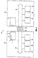
- FIG. 1 is a schematic block diagram of a dockable computer system 10 including a portable computer 20 and a docking or host station 22.
- Portable computer 20 is a mobile computer unit including a CPU 26, a system bus 24, and a docking safe circuit 8.
- Portable computer 20 can also include a peripheral device 28 and a peripheral device 30.
- System bus 24 couples CPU 26, peripheral device 28, and peripheral device 30.
- An external connector 34 is also coupled with system bus 24.
- System bus 24 can be a CPU-to-memory bus, an I/O bus, a standard bus, PCI bus, a sub-bus, a span bus or any other type of bus functionally operative in the microcomputer environment.
- components of computer system 10 can be coupled together via bridges, sub-buses and other conductors (not shown), and CPU 26 can be coupled to bus 24 via a host/PCI bus bridge (not shown).
- Docking station 22 includes a docking safe circuit 12. Docking station 22 can also include a microcontroller 35, a peripheral device 40 and a peripheral device 42. Microcontroller 35 can be replaced by a more powerful microprocessor as warranted by applications for system 10, and it is within the scope of the present invention to utilize a minicomputer as the host system should the user so desire. Docking station 22 is a host station which can have superior, equal or inferior computing power compared to portable computer 20, depending on design needs, requirements or constraints.
- Docking bus 46 couples microcontroller 35, peripheral device 40 and peripheral device 42. An external connector 36 is also coupled to docking bus 46. Docking bus 46 can be a host-to-memory bus, an I/O bus, a standard bus, a PCI bus, a sub-bus, a span bus or any other type of bus as noted generally above. Docking bus 46 can also be coupled to docking safe circuit 12.
- docking station 22 receives portable computer 20 so dockable computer system 10 operates as a single desktop computer or an integrated computer system.
- external connectors 34 and 36 are physically coupled.
- CPU 26 can electrically communicate with components in docking station 22 such as peripheral device 42, peripheral device 40, or microcontroller 35 via system bus 24, connectors 34 and 36, and docking bus 46.
- Docking safe circuit 8 can be disposed intermediate external connector 34 and system bus 24 as an in-line device or coupled to system bus 24 as an off-line device. Docking safe circuit 8 includes a DOCK input 9 for receiving a DOCK signal.
- the DOCK signal is preferably provided by dockable computer system 10 prior to or during a docking event.
- the DOCK signal indicates that docking safe circuit 8 should take appropriate action to protect system bus 24 as it is coupled to or uncoupled from docking bus 46. The operation of docking safe circuit 8 in dockable computer system 10 is described below with reference to Figures 1 and 6.
- a docking event 200 begins when a user of system 10 or an automatic ejection or insertion mechanism (not shown) initiates the coupling or uncoupling of connectors 34 and 36 (at block 220).
- Dockable computer system 10 preferably includes a docking event sense circuit or other monitoring device which senses the impending docking event 200 and generates a DOCK signal (at block 222).
- the DOCK signal is a warning that buses 24 and 46 are about to be coupled or uncoupled.
- the DOCK signal is received at dock input 9 of docking safe circuit 8.
- Docking safe circuit 8 drives system bus 24 to a docking safe state in response to the DOCK signal.
- the docking safe state should be a state in which buses 24 and 46 can be coupled or uncoupled with minimal signaling failures, current discharge and component damage.
- the docking safe state is an electrically benign state or a state where: the ground conductors of buses 24 and 46 are referenced to a common ground potential; the signal levels on buses 24 and 46 are not transitioning or "quiet"; the bidirectional terminals of bus 24 are set to an output state; the bidirectional terminals of bus 46 are set to an input state; and the signaling levels on buses 24 and 46 have equal potentials.
- the protective measures associated with the docking safe state should also be balanced with practical considerations such as the amount of time required to place buses 24 and 46 in the docking safe state.
- the docking safe state should be reached within 0.5 seconds so the user is not subjected to a perceptible delay as system 10 changes states.
- buses 24 and 46 can be designed with inherent translation, isolation, and protection features, thereby eliminating the need for certain aspects of the docking safe state. In this sense, therefore, the docking safe state is system defined and may be manifested in a variety of protective measures for buses 24 and 46.
- docking safe circuit 8 drives system bus 24 to a docking safe state so buses 24 and 46 may be safely coupled or uncoupled when portable computer 20 and docking station 22 are powered ON.
- docking safe circuit 8 references all ground conductors on system bus 24 and docking bus 46 to a common ground (block 224). Docking safe circuit 8 can utilize a ground connection interface (not shown) such as ground pins or a shield conductor associated with connectors 34 and 36 to ensure that buses 24 and 46 have the same ground potential.
- Portable computer 20 generally has a "floating" ground level which can be referenced to the ground level of docking station 22 when connectors 34 and 35 are coupled. The ground level of docking station 22 is advantageously referenced to 0 VDC.
- Docking safe circuit 8 also quiets or renders inactive system bus 24 in response to the DOCK signal (block 226).
- Docking safe circuit 8 may utilize similar techniques to those discussed in U.S. Patent application Serial No. 08/217,951, filed March 25, 1994, entitled “An Apparatus and Method for Generating Hot Docking Capabilities for a Dockable Computer System,” for quieting signals on system bus 24.
- docking safe circuit 12 may utilize the same techniques to quiet docking bus 46.
- Docking safe circuit 8 also sets all bidirectional terminals on bus 24 to the output state (block 228).
- a signal keeper circuit 51 drives the bidirectional terminals to the output state.
- Signal keeper circuit 51 is preferably comprised of low current back-to-back inverters which maintain the current pin status on bus 24. The inverters are easily overdriven by other components such as CPU 26 and peripheral devices 28 and 30 coupled to bus 24. The inverters are also designed to use as little battery power as possible and yet reliably drive the bidirectional terminals to the output state.
- Docking safe circuit 12 sets all bidirectional terminals on docking bus 46 to the input state (block 232).
- components on bus 46 such as peripheral devices 40 and 42 have a default state which sets the bidirectional terminals to the input state.
- microcontroller 35 may set peripheral devices 40 and 42 in a reset state so that the bidirectional terminals are set to the input state.
- Docking safe circuit 8 also sets the logic high signal levels (VCC) in portable computer 20 and docking station 22 to the same voltage level (block 236).
- docking station 22 includes components such as peripheral devices 40 and 42 which may operate at either a 3.3 VDC or 5.0 VDC signal level, and docking safe circuit 8 or docking safe circuit 12 set the logic high signal level of components of docking station 22 to the logic high signal level of portable computer 20.
- portable computer 20 has a 3.3 VDC logic high signal level.
- docking safe circuit 8 or docking safe circuit 12 may isolate buses 24 and 46 and include voltage translation circuitry for converting the logic high voltage level of portable computer 20 or docking station 22 to a compatible level.
- docking safe circuit 8 drives system bus 12 to a docking safe state, thereby protecting bus 24 during docking event 200.
- System 100 generally includes a bus arbiter 38 integrated with CPU 26, a docking agent 32 and a docking control circuit 44. The operations of docking safe circuit 8 and docking safe circuit 12 are performed by docking agent 32 and docking control circuit 44, respectively.
- Docking agent 32 is coupled to system bus 24 as an off-line device; docking control circuit 44 is coupled to docking bus 46 as an off-line device.
- Dockable computer system 100 preferably provides the DOCK signal as an ADVANCE NOTICE signal warning of the impending docking event.
- docking control circuit 44 includes circuitry for sensing an impending docking event and for communicating the ADVANCE NOTICE signal across a communication link 50, as described below.
- the ADVANCE NOTICE signal can be provided on system bus 24, docking bus 46, communication link 50, or various control lines in dockable computer system 10.
- communication link 50 preferably provides an infrared ADVANCE NOTICE (warning) signal which is received by docking agent 32.
- Communication link 50 can be an electromagnetic communication link, long pin interface, or wireless communication link such as those disclosed in U.S. patent application Serial No. 08/217,952, filed March 25, 1994, and entitled, "Dockable Computer System Capable of Electric and Electromagnetic Communication", assigned to the assignee of the present invention.
- Portable computer 20 or docking station 22 can provide a software-actuated ADVANCE NOTICE signal or a user-actuated ADVANCE NOTICE signal.
- Bus arbiter 38 includes a quiet request input 53 coupled to a quiet request control line 57 and a quiet acknowledge output 42 coupled to a quiet acknowledge control line 49.
- CPU 26 is able to monitor bus activity on bus 24 via a bus input 27.
- Bus input 27 preferably includes control lines for receiving signals such as a FRAME signal and an IRDY (Initiator Ready) signal utilized by the PCI protocol which indicate a transaction is occurring on bus 24.
- Docking agent 32 includes a quiet acknowledge input 39 coupled to quiet acknowledge control line 49, and a quiet request output 43 coupled to quiet request control line 57.
- Bus arbiter 38 is advantageously integrated with CPU 26 so bus arbiter 38 is capable of disconnecting current bus cycles by providing an idle, stop, halt or other bus cycle control command to CPU 26 and peripheral devices 28 and 30.
- bus arbiter 38 may signal CPU 26 or a bus bridge (not shown) to disconnect the current bus cycle.
- Bus arbiter 38 can also be integrated with other components such as a host or PCI bus bridge (not shown).
- Bus arbiter 38 is designed along the lines and performs the operations of that circuitry described in U.S. patent application Serial No. 08/255,663, filed June 9, 1994, entitled "An Apparatus and Method for Granting Control of a Bus in a Computer System.”
- Docking agent 32 ensures that system bus 24 is in the docking safe state. More particularly, docking agent 32 cooperates with bus arbiter 48 to quiet or render inactive system bus 24 in response to the DOCK signal. Docking agent 32 provides a QUIET REQUEST (primary request) signal on QUIET REQUEST control line 57 in response to the DOCK signal. Arbiter 38 receives the QUIET REQUEST signal and de-asserts all grants given to other bus masters such as CPU 26 and peripheral devices 28 and 30. After the current transaction on bus 24 is completed, arbiter 38 grants bus ownership to docking agent 32 by providing a QUIET ACKNOWLEDGE (primary knowledge) signal across QUIET ACKNOWLEDGE control line 49. Preferably, arbiter 38 grant docking agent 32 a time-bound access to system bus 24. Docking agent 32 quiets system bus 24 in response to the QUIET ACKNOWLEDGE signal.
- QUIET REQUEST primary request
- Arbiter 38 receives the QUIET REQUEST signal
- Docking agent 32 also employs signal keeper circuit 51 within portable computer 20, or other weak driving entities, to maintain the current pin status on system bus 24. Maintaining the current pin status inherently sets all bidirectional terminals on system bus 24 to the output state. Docking agent 32 is preferably designed along the lines and performs the operations of that circuitry described in U.S. patent application Serial No. 08/217,951, filed March 25, 1994, entitled "An Apparatus and Method for Achieving Hot Docking Capabilities for a Dockable Computer System.”
- Portable computer 20 and docking station 22 of a dockable computer system 110 illustrated in Figure 3 are similar to dockable computer system 10 discussed with reference to Figure 1.
- Dockable computer system 110 includes a PCI bus 21, a PCI master arbiter 52, an external bus master 31, a host-to-PCI bridge 23, a docking control circuit 45 and a memory 37.
- CPU 26 is coupled to memory 37 via a high speed bus 29.
- CPU 26 is coupled to PCI bus 21 through host-to-PCI bus bridge 23.
- External bus master 31 and signal keepers 51 operate similarly to docking safe circuit 8 ( Figure 1), and drive PCI bus 21 to a docking safe state.
- Docking control circuit 45 is coupled as an in-line device between a connector bus 47 and bus 46.
- external bus master 31 provides a QUIET REQUEST (primary request) signal on quiet request control line 57 in response to receiving the DOCK signal on communication link 50.
- PCI master arbiter 52 receives the QUIET REQUEST signal and de-asserts all grants given to other bus masters such as peripheral devices 28 and 30.
- PCI master arbiter 52 grants bus ownership to external bus master 31 by providing a QUIET ACKNOWLEDGE (primary acknowledge) signal across quiet acknowledge control line 49, thereby quieting system bus 24.
- PCI master arbiter 52 grants a time bound access to bus master 31. External bus master 31 is thus able to quiet PCI bus 21 in response to the DOCK signal.
- Central resource keepers in signal keeper circuit 51 preferably maintain the current signaling level of conductors on PCI bus 21 and drive the bidirectional terminals on bus 21 to the output state.
- Signal keeper circuit 51 may be integrated within PCI master arbiter 52, host-to-PCI bridge 23, or other device coupled to PCI bus 21.
- the central resource keepers are weak driving entities for retaining the signals on PCI bus 21; weak driving entities may be easily overdriven by other devices on PCI bus 21 so that they do not interfere with normal operations of bus 21.
- Docking station 22 includes a docking control circuit 45 shown to be an in-line device. Docking control circuit 45 can perform the operations of docking safe circuit 12 ( Figure 1) and drive docking bus 46 to a docking safe state. Docking control circuit 45 sets the states of the bidirectional terminals on docking bus 46 to an input state by holding peripheral devices 40 and 42 in a reset state. According to PCI protocol, the reset state forces all bidirectional terminals to the input state.
- docking control circuit 45 can drive connector bus 47 to an electrically benign state so connectors 34 and 35 may be safely coupled or uncoupled.
- the electrically benign state is a docking safe state in which connector bus 47 is essentially powered off.
- Docking control circuit 45 can drive connector bus 47 to the electrically benign state by driving tri-state terminals on bus 47 to the high impedance state. Active signals do not exist on bus 47 when it is in the electrically benign state.
- buses 21 and 46 are preferably quieted before allowing communication across docking control circuit 45 so signaling errors are prevented.
- Portable computer 20 and docking station 22 of a dockable computer system 120 illustrated in Figure 4 operate similarly to dockable computer system 10 discussed with reference to Figure 1.
- dockable computer system 120 in Figure 4 includes a buffer circuit or a docking bridge 33 and docking control circuit 45, shown to be in-line devices, and a bus arbiter 52 shown to be a stand-alone, off-line device.
- Docking agent 32 and docking control circuit 44 may be utilized with a bus arbiter 60.
- bus arbiter 60 may be integrated with CPU 26.
- Docking bridge 33 is coupled between system bus 24 and a connector bus 25 and includes a signal keeper circuit 48. Docking bridge 33 and docking control circuit 45 provide the functions of docking safe circuit 8 and docking safe circuit 12 ( Figure 1), respectively.
- Connector bus 25 is preferably coupled to external connector 34 and connector bus 47 is preferably coupled to external connector 36.
- docking bridge 33 drives connector bus 25 to the electrically benign state and docking control circuit 45 drives connector bus 47 to the electrically benign state.
- docking bridge 33 and docking control circuit 45 can additionally quiet system bus 24 and docking bus 46 to ensure incomplete bus cycles or signals are not transmitted on buses 24 and 46.
- connectors 34 and 36 can be coupled. Once connectors 34 and 36 are coupled and buses 24 and 46 are quieted, docking bridge 33 and docking control circuit 45 allow communication between buses 24 and 46.
- Docking bridge 33 and docking control circuit 45 operate as in-line devices and can isolate connector bus 25 from system bus 24 and connector bus 47 from docking bus 46.
- Docking bridge 33 and docking control circuit 45 preferably include filter capability, drive capability, voltage level translation capability and buffering capability. Buffering capability can include tri-state inputs and outputs for isolating buses 24 and 46 by utilizing a high impedance state. Docking bridge 33 and docking control circuit 45 are discussed in more detail in United States patent application Serial No. 08/217,951, filed March 25, 1994, entitled "An Apparatus and Method for Achieving Hot Docking Capabilities for a Dockable Computer System.”
- Portable computer 20 and docking station 22 of dockable computer system 130 illustrated in Figure 5 are similar to dockable computer system 110 discussed with reference to Figures 3 and 4.
- Dockable computer system 130 includes a buffer circuit or a docking bridge 80 coupled to PCI bus 21.
- Docking bridge 80, external bus master 31 and PCI master arbiter 52 cooperate to perform the operations of docking safe circuit 8 ( Figure 1).
- Docking bridge 80 is an in-line PCI-to-PCI bridge disposed electrically intermediate connector bus 25 and PCI bus 21.
- Docking bridge 80 ensures connector bus 25 is in an electrically benign state in response to the DOCK signal. Docking bridge 80 also provides a signal on a conductor 81 so that external bus master 31 requests control of bus 21 by providing a QUIET REQUEST across QUIET REQUEST control line 57. PCI master arbiter 52 grants control of bus 21 to external bus master 31 so PCI bus 21 may be quieted. External bus master 31 does not necessarily need a time-bound access because docking bridge 80 advantageously holds connector bus 25 in the electrically benign state until bus 21 is quieted.
- PCI master arbiter can monitor PCI bus 21 via an input 41 to determine if PCI bus 21 is quiet. Once connector 34 and 36 are coupled and bus 21 is quiet, docking bridge 80 signals external bus master 31 to remove the QUIET REQUEST signal at QUIET REQUEST control line 57. Docking bridge 80 allows communication between buses 24 and 46 after the docking event is completed.
Abstract
Description
- The present invention relates generally to a dockable computer system in which a portable computer is associated with a stationary host computer through a resident station and, more particularly, to a system and method for implementing the system in a manner enabling the portable computer and resident station to be physically combined or separated when the units are powered on.
- A dockable computer system includes a portable computer unit, usually a notebook or laptop, and a stationary or base computer unit having a docking station for receiving the portable computer unit. Dockable computer systems may be operated in a docked state, in which both computer units are physically associated as a generally unified system, or the remote unit may be separated from its host for independent operation in an undocked state.
- Rudimentary docking systems of the foregoing variety have been designed in an effort to meet the needs of today's mobile computer users for "ubiquitous" computing system capabilities, to fulfill their computing needs in diverse aspects of their professional and personal lives and in sundry locations. Contemporary dockable computer systems approach this problem through a single system having a detachable mobile computing component or subsystem.
- The expandable desktop computer provides greater storage resources, network connectivity, larger displays, and other superior facilities which are necessary for the typical range of generally demanding home and office computing. The portable computer (mobile computer unit) allows the user to have computing capabilities while outside the home or office by detaching that component with its indigenous hardware and resident software. The computing capabilities of the portable computer are somewhat limited due to size, weight and power constraints but represent the best available approach in these embryonic attempts to balance portable mobility needs.
- When the user leaves the host environment of home or office, the portable computer is undocked (that is, physically detached) from the docking station of the stationary computer unit. Applications, files, and other data needed for the mobile computing task must have previously been stored in the portable computer. When the user returns to the host environment, the portable computer is reunited (docked) with the docking station so the applications, the files and other data are stored and maintained in a single location. Thus, the use of a dockable computer system allows the user to have access to any needed applications, files and other data just before embarking on the mobile computing task.
- When the dockable computer system changes from the undocked state to the docked state or the docked state to the undocked state (a docking event), protective measures are required to prevent catastrophic failures caused by physically connecting or disconnecting the active buses of the portable computer and the docking station. For example, the bus of the portable computer can be referenced to a substantially different ground level or signal level than the bus of the docking station. Connecting these buses can cause large inrushes of current, especially through the ground conductors, and signal overdrive conditions. Large inrushes of current and signal overdrive conditions may cause component damage and excessive battery wear or deterioration. Also, bidirectional terminals on the portable computer and bidirectional terminals on the docking station may be inappropriately set to both be in an input state or to both be in an output state. Such a situation can cause input leakages (resulting in excessive battery wear) and signaling failures.
- Contemporary dockable computer systems are typically "cold docking" systems which protect the buses only by powering off the portable computer and docking station, rendering the buses inactive so protective measures are not required. These "cold docking" systems are disadvantageous because the user must wait for the dockable computer system to be turned on, rebooted, and reconfigured before the dockable computer system is operational in the docked state. These systems are inconvenient because of the amount of time required to change from the docked state to the undocked state or from the undocked state to the docked state.
- There is a need for a "hot docking" computer system and a "warm docking" computer system. A "hot docking" computer system as envisioned herein is a dockable computer system which can change states with the portable computer running at full power. A "warm docking" system may be thought of as a dockable computer system which can change when the portable computer is in a reduced power state when the portable computer is not running at full power. Examples of the reduced power state are the suspend state and standby state now incorporated in some microprocessor systems. Hot docking and warm docking systems advantageously enable the user to more immediately begin computer tasks because the systems are powered on throughout the docking event.
- Thus, there is a need for a dockable computer system which includes circuitry that allows the dockable computer system to change states while powered on. More particularly, there is a need for a dockable computer system which drives the active buses of the portable computer and docking station to a dockable state or a docking safe state when the system is docked or undocked.
- The present invention relates to a portable computer for use in a dockable computer system capable of assuming at least two states, a docked state and an undocked state, with a host station. The dockable computer system is in the docked state when the portable computer is operatively associated with the host station and is in the undocked state when the portable computer is physically separate from the host station. The dockable computer system includes a computer bus, a docking safe circuit, and a dock circuit. The docking safe circuit communicates with the computer bus and includes a dock input. The dock safe circuit drives the computer bus to a docking safe state in response to a DOCK signal on the dock input. The dock circuit communicates with the dock safe circuit and provides the DOCK signal in response to the dockable computer system changing states.
- The present invention also relates to a method of docking or undocking a portable computer and a host station of a dockable computer system. The portable computer has a computer bus, and the host station has a host bus. The dockable computer system includes a dock circuit for generating a DOCK signal in response to docking or undocking the portable computer. The computer bus is physically electrically coupled with the host bus when the portable computer is docked with the host station. The method includes the steps of receiving the DOCK signal provided by the dock circuit, driving the computer bus to a docking safe state in response to the DOCK signal, and coupling or uncoupling the host bus and the computer bus.
- The present invention further relates to a portable computer operable in an undocked state or a docked state with a station having a station bus. The computer includes a bus and a computer connector coupled to the bus, and the station includes a station connector coupled to the station bus. The computer connector is coupled to the station connector when the computer is operable in the docked state, and the computer connector is separate from the station connector when the computer is operable in the undocked state. The computer includes a CPU and a bus isolation circuit. The CPU is capable of physical electrical communication with the bus of the computer. The bus isolation circuit is coupled between the bus of the computer and the computer connector. The bus isolation circuit isolates the bus of the computer when the computer changes states.
- The present invention still further relates to an improved dockable computer system including a host computer station having a station bus and a mobile computer unit having a unit bus. The dockable computer system is capable of residing in at least two distinct states, a docked state in which the unit is operatively associated with the station, and an undocked state in which the unit is physically separate from the station. The improvement includes a docking safe circuit coupled to the unit bus. The docking safe circuit drives the unit bus to a docking safe state when the system changes from the undocked state to the docked state or from the docked state to the undocked state.
- In one aspect of the present invention, a docking agent quiets the bus of the portable computer. Signal keepers within the portable computer force bidirectional terminals to the output state to drive the bus to a docking safe state. In another aspect of the present invention, a bus isolation circuit drives a pin boundary between the portable computer and docking station to an electrically benign state and forces the system bus to a quiet state. After these two states or other docking safe states are reached, the bus isolation circuit allows communication between the portable computer and docking station. The bus isolation circuit is preferably an in-line device which isolates and protects the bus of the portable computer as the portable computer is docked or undocked.
- In yet another aspect of the present invention, the docking safe state is a bus state characterized by the following conditions: the ground signal levels in the host station and portable computer are referenced to a common ground potential, the signals on the buses are not transitioning or "quiet", the bidirectional terminals of the portable computer are set to an output state, the bidirectional terminals of the host station are set to an input state, and the logic high (Vcc) signal levels of the portable computer and host station have equal voltage potentials. Alternatively, the docking safe state can include only two or more of the foregoing conditions.
- The docking safe state advantageously reduces the potential for electrostatic discharge (ESD) between the portable computer and the docking station and prevents unnecessary signal overdrive and input leakage, thereby extending the life of the battery associated with the portable computer. The docking safe state also effectively reduces the potential for signaling failures and component malfunction caused by the docking event.
- The invention will hereafter be described with reference to the accompanying drawings, wherein like numerals denote like elements, and:
- Figure 1 schematically illustrates a dockable computer system employing an exemplary embodiment of the present invention;
- Figure 2 is a more detailed schematic diagram of the dockable computer system illustrated in Figure 1 in accordance with a first exemplary architecture;
- Figure 3 is a more detailed block diagram of the dockable computer system illustrated in Figure 2 in accordance with a second exemplary architecture;
- Figure 4 is a more detailed block diagram of the dockable computer system illustrated in Figure 1 in accordance with a third exemplary architecture;
- Figure 5 is a more detailed block diagram of the dockable computer system illustrated in Figure 1 in accordance with a fourth exemplary architecture; and
- Figure 6 is a simplified flow chart of the operation of the dockable computer system illustrated in Figure 1 during a docking event.
- Figure 1 is a schematic block diagram of a
dockable computer system 10 including aportable computer 20 and a docking orhost station 22.Portable computer 20 is a mobile computer unit including aCPU 26, asystem bus 24, and a docking safe circuit 8.Portable computer 20 can also include aperipheral device 28 and aperipheral device 30. -
System bus 24couples CPU 26,peripheral device 28, andperipheral device 30. Anexternal connector 34 is also coupled withsystem bus 24.System bus 24 can be a CPU-to-memory bus, an I/O bus, a standard bus, PCI bus, a sub-bus, a span bus or any other type of bus functionally operative in the microcomputer environment. Alternatively, components ofcomputer system 10 can be coupled together via bridges, sub-buses and other conductors (not shown), andCPU 26 can be coupled tobus 24 via a host/PCI bus bridge (not shown). -
Docking station 22 includes a dockingsafe circuit 12.Docking station 22 can also include amicrocontroller 35, aperipheral device 40 and aperipheral device 42.Microcontroller 35 can be replaced by a more powerful microprocessor as warranted by applications forsystem 10, and it is within the scope of the present invention to utilize a minicomputer as the host system should the user so desire.Docking station 22 is a host station which can have superior, equal or inferior computing power compared toportable computer 20, depending on design needs, requirements or constraints. - Docking
bus 46couples microcontroller 35,peripheral device 40 andperipheral device 42. Anexternal connector 36 is also coupled to dockingbus 46. Dockingbus 46 can be a host-to-memory bus, an I/O bus, a standard bus, a PCI bus, a sub-bus, a span bus or any other type of bus as noted generally above. Dockingbus 46 can also be coupled to dockingsafe circuit 12. - When
dockable computer system 10 is in an undocked state,external connectors system bus 24 anddocking bus 46 are not in physical, electrical communication. In this undocked state,portable computer 20 is operable as a stand-alone computer and is physically separate fromdocking station 22. - In the docked state,
docking station 22 receivesportable computer 20 sodockable computer system 10 operates as a single desktop computer or an integrated computer system. Whendockable computer system 10 is in this docked state,external connectors connectors CPU 26 can electrically communicate with components indocking station 22 such asperipheral device 42,peripheral device 40, ormicrocontroller 35 viasystem bus 24,connectors docking bus 46. - Docking safe circuit 8 can be disposed intermediate
external connector 34 andsystem bus 24 as an in-line device or coupled tosystem bus 24 as an off-line device. Docking safe circuit 8 includes a DOCK input 9 for receiving a DOCK signal. The DOCK signal is preferably provided bydockable computer system 10 prior to or during a docking event. The DOCK signal indicates that docking safe circuit 8 should take appropriate action to protectsystem bus 24 as it is coupled to or uncoupled from dockingbus 46. The operation of docking safe circuit 8 indockable computer system 10 is described below with reference to Figures 1 and 6. - Referring to Figure 6, a
docking event 200 begins when a user ofsystem 10 or an automatic ejection or insertion mechanism (not shown) initiates the coupling or uncoupling ofconnectors 34 and 36 (at block 220).Dockable computer system 10 preferably includes a docking event sense circuit or other monitoring device which senses theimpending docking event 200 and generates a DOCK signal (at block 222). The DOCK signal is a warning thatbuses drives system bus 24 to a docking safe state in response to the DOCK signal. - System and application parameters typically define the docking safe state and therefore the precautions necessary to adequately protect
system bus 24 anddocking bus 46 duringdocking event 200. For instance, the docking safe state should be a state in whichbuses buses buses bus 24 are set to an output state; the bidirectional terminals ofbus 46 are set to an input state; and the signaling levels onbuses buses system 10 changes states. Alternatively,buses buses drives system bus 24 to a docking safe state sobuses portable computer 20 anddocking station 22 are powered ON. - With reference to Figure 6, docking safe circuit 8 references all ground conductors on
system bus 24 anddocking bus 46 to a common ground (block 224). Docking safe circuit 8 can utilize a ground connection interface (not shown) such as ground pins or a shield conductor associated withconnectors buses Portable computer 20 generally has a "floating" ground level which can be referenced to the ground level ofdocking station 22 whenconnectors docking station 22 is advantageously referenced to 0 VDC. - Docking safe circuit 8 also quiets or renders
inactive system bus 24 in response to the DOCK signal (block 226). Docking safe circuit 8 may utilize similar techniques to those discussed in U.S. Patent application Serial No. 08/217,951, filed March 25, 1994, entitled "An Apparatus and Method for Generating Hot Docking Capabilities for a Dockable Computer System," for quieting signals onsystem bus 24. Similarly, dockingsafe circuit 12 may utilize the same techniques toquiet docking bus 46. - Docking safe circuit 8 also sets all bidirectional terminals on
bus 24 to the output state (block 228). Preferably, asignal keeper circuit 51 drives the bidirectional terminals to the output state.Signal keeper circuit 51 is preferably comprised of low current back-to-back inverters which maintain the current pin status onbus 24. The inverters are easily overdriven by other components such asCPU 26 andperipheral devices bus 24. The inverters are also designed to use as little battery power as possible and yet reliably drive the bidirectional terminals to the output state. - Docking
safe circuit 12 sets all bidirectional terminals on dockingbus 46 to the input state (block 232). Preferably, components onbus 46 such asperipheral devices microcontroller 35 may setperipheral devices - Docking safe circuit 8 also sets the logic high signal levels (VCC) in
portable computer 20 anddocking station 22 to the same voltage level (block 236). Preferably,docking station 22 includes components such asperipheral devices safe circuit 12 set the logic high signal level of components ofdocking station 22 to the logic high signal level ofportable computer 20. Generally,portable computer 20 has a 3.3 VDC logic high signal level. Alternatively, docking safe circuit 8 or dockingsafe circuit 12 may isolatebuses portable computer 20 ordocking station 22 to a compatible level. - After
system bus 24 anddocking bus 46 reach the docking safe state (blocks 224-236),buses drives system bus 12 to a docking safe state, thereby protectingbus 24 duringdocking event 200. -
Portable computer 20 anddocking station 22 of adockable computer system 100 illustrated in Figure 2 are similar todockable computer system 10 discussed with reference to Figure 1.System 100 generally includes abus arbiter 38 integrated withCPU 26, adocking agent 32 and adocking control circuit 44. The operations of docking safe circuit 8 and dockingsafe circuit 12 are performed by dockingagent 32 anddocking control circuit 44, respectively.Docking agent 32 is coupled tosystem bus 24 as an off-line device;docking control circuit 44 is coupled to dockingbus 46 as an off-line device. -
Dockable computer system 100 preferably provides the DOCK signal as an ADVANCE NOTICE signal warning of the impending docking event. Preferably,docking control circuit 44 includes circuitry for sensing an impending docking event and for communicating the ADVANCE NOTICE signal across acommunication link 50, as described below. - The ADVANCE NOTICE signal can be provided on
system bus 24,docking bus 46,communication link 50, or various control lines indockable computer system 10. For example, whendockable computer system 10 changes from an undocked state to a docked state (an external event),communication link 50 preferably provides an infrared ADVANCE NOTICE (warning) signal which is received by dockingagent 32.Communication link 50 can be an electromagnetic communication link, long pin interface, or wireless communication link such as those disclosed in U.S. patent application Serial No. 08/217,952, filed March 25, 1994, and entitled, "Dockable Computer System Capable of Electric and Electromagnetic Communication", assigned to the assignee of the present invention.Portable computer 20 ordocking station 22 can provide a software-actuated ADVANCE NOTICE signal or a user-actuated ADVANCE NOTICE signal. -
Bus arbiter 38 includes aquiet request input 53 coupled to a quietrequest control line 57 and a quiet acknowledgeoutput 42 coupled to a quiet acknowledgecontrol line 49.CPU 26 is able to monitor bus activity onbus 24 via abus input 27.Bus input 27 preferably includes control lines for receiving signals such as a FRAME signal and an IRDY (Initiator Ready) signal utilized by the PCI protocol which indicate a transaction is occurring onbus 24.Docking agent 32 includes a quiet acknowledgeinput 39 coupled to quiet acknowledgecontrol line 49, and aquiet request output 43 coupled to quietrequest control line 57. -
Bus arbiter 38 is advantageously integrated withCPU 26 sobus arbiter 38 is capable of disconnecting current bus cycles by providing an idle, stop, halt or other bus cycle control command toCPU 26 andperipheral devices bus arbiter 38 may signalCPU 26 or a bus bridge (not shown) to disconnect the current bus cycle.Bus arbiter 38 can also be integrated with other components such as a host or PCI bus bridge (not shown).Bus arbiter 38 is designed along the lines and performs the operations of that circuitry described in U.S. patent application Serial No. 08/255,663, filed June 9, 1994, entitled "An Apparatus and Method for Granting Control of a Bus in a Computer System." -
Docking agent 32 ensures thatsystem bus 24 is in the docking safe state. More particularly,docking agent 32 cooperates withbus arbiter 48 to quiet or renderinactive system bus 24 in response to the DOCK signal.Docking agent 32 provides a QUIET REQUEST (primary request) signal on QUIETREQUEST control line 57 in response to the DOCK signal.Arbiter 38 receives the QUIET REQUEST signal and de-asserts all grants given to other bus masters such asCPU 26 andperipheral devices bus 24 is completed,arbiter 38 grants bus ownership to dockingagent 32 by providing a QUIET ACKNOWLEDGE (primary knowledge) signal across QUIET ACKNOWLEDGEcontrol line 49. Preferably,arbiter 38 grant docking agent 32 a time-bound access tosystem bus 24.Docking agent 32 quietssystem bus 24 in response to the QUIET ACKNOWLEDGE signal. -
Docking agent 32 also employssignal keeper circuit 51 withinportable computer 20, or other weak driving entities, to maintain the current pin status onsystem bus 24. Maintaining the current pin status inherently sets all bidirectional terminals onsystem bus 24 to the output state.Docking agent 32 is preferably designed along the lines and performs the operations of that circuitry described in U.S. patent application Serial No. 08/217,951, filed March 25, 1994, entitled "An Apparatus and Method for Achieving Hot Docking Capabilities for a Dockable Computer System." -
Portable computer 20 anddocking station 22 of adockable computer system 110 illustrated in Figure 3 are similar todockable computer system 10 discussed with reference to Figure 1.Dockable computer system 110 includes aPCI bus 21, aPCI master arbiter 52, anexternal bus master 31, a host-to-PCI bridge 23, adocking control circuit 45 and amemory 37.CPU 26 is coupled tomemory 37 via ahigh speed bus 29.CPU 26 is coupled toPCI bus 21 through host-to-PCI bus bridge 23.External bus master 31 andsignal keepers 51 operate similarly to docking safe circuit 8 (Figure 1), and drivePCI bus 21 to a docking safe state.Docking control circuit 45 is coupled as an in-line device between aconnector bus 47 andbus 46. - In operation,
external bus master 31 provides a QUIET REQUEST (primary request) signal on quietrequest control line 57 in response to receiving the DOCK signal oncommunication link 50.PCI master arbiter 52 receives the QUIET REQUEST signal and de-asserts all grants given to other bus masters such asperipheral devices PCI bus 21 is completed,PCI master arbiter 52 grants bus ownership toexternal bus master 31 by providing a QUIET ACKNOWLEDGE (primary acknowledge) signal across quiet acknowledgecontrol line 49, thereby quietingsystem bus 24. Preferably,PCI master arbiter 52 grants a time bound access tobus master 31.External bus master 31 is thus able to quietPCI bus 21 in response to the DOCK signal. - Central resource keepers in
signal keeper circuit 51 preferably maintain the current signaling level of conductors onPCI bus 21 and drive the bidirectional terminals onbus 21 to the output state.Signal keeper circuit 51 may be integrated withinPCI master arbiter 52, host-to-PCI bridge 23, or other device coupled toPCI bus 21. The central resource keepers are weak driving entities for retaining the signals onPCI bus 21; weak driving entities may be easily overdriven by other devices onPCI bus 21 so that they do not interfere with normal operations ofbus 21. -
Docking station 22 includes adocking control circuit 45 shown to be an in-line device.Docking control circuit 45 can perform the operations of docking safe circuit 12 (Figure 1) and drive dockingbus 46 to a docking safe state.Docking control circuit 45 sets the states of the bidirectional terminals on dockingbus 46 to an input state by holdingperipheral devices - Alternatively,
docking control circuit 45 can driveconnector bus 47 to an electrically benign state soconnectors connector bus 47 is essentially powered off.Docking control circuit 45 can driveconnector bus 47 to the electrically benign state by driving tri-state terminals onbus 47 to the high impedance state. Active signals do not exist onbus 47 when it is in the electrically benign state. For this type of docking safe state,buses docking control circuit 45 so signaling errors are prevented. -
Portable computer 20 anddocking station 22 of adockable computer system 120 illustrated in Figure 4 operate similarly todockable computer system 10 discussed with reference to Figure 1. However,dockable computer system 120 in Figure 4 includes a buffer circuit or adocking bridge 33 anddocking control circuit 45, shown to be in-line devices, and abus arbiter 52 shown to be a stand-alone, off-line device.Docking agent 32 and docking control circuit 44 (Figure 2) may be utilized with abus arbiter 60. Alternately,bus arbiter 60 may be integrated withCPU 26. - Docking
bridge 33 is coupled betweensystem bus 24 and aconnector bus 25 and includes asignal keeper circuit 48. Dockingbridge 33 anddocking control circuit 45 provide the functions of docking safe circuit 8 and docking safe circuit 12 (Figure 1), respectively.Connector bus 25 is preferably coupled toexternal connector 34 andconnector bus 47 is preferably coupled toexternal connector 36. Whensystem 120 is about to change states, dockingbridge 33drives connector bus 25 to the electrically benign state anddocking control circuit 45drives connector bus 47 to the electrically benign state. - After
connector buses bridge 33 anddocking control circuit 45 can additionallyquiet system bus 24 anddocking bus 46 to ensure incomplete bus cycles or signals are not transmitted onbuses buses connectors connectors buses bridge 33 anddocking control circuit 45 allow communication betweenbuses - Docking
bridge 33 anddocking control circuit 45 operate as in-line devices and can isolateconnector bus 25 fromsystem bus 24 andconnector bus 47 from dockingbus 46. Dockingbridge 33 anddocking control circuit 45 preferably include filter capability, drive capability, voltage level translation capability and buffering capability. Buffering capability can include tri-state inputs and outputs for isolatingbuses bridge 33 anddocking control circuit 45 are discussed in more detail in United States patent application Serial No. 08/217,951, filed March 25, 1994, entitled "An Apparatus and Method for Achieving Hot Docking Capabilities for a Dockable Computer System." -
Portable computer 20 anddocking station 22 ofdockable computer system 130 illustrated in Figure 5 are similar todockable computer system 110 discussed with reference to Figures 3 and 4.Dockable computer system 130 includes a buffer circuit or adocking bridge 80 coupled toPCI bus 21. Dockingbridge 80,external bus master 31 andPCI master arbiter 52 cooperate to perform the operations of docking safe circuit 8 (Figure 1). Dockingbridge 80 is an in-line PCI-to-PCI bridge disposed electricallyintermediate connector bus 25 andPCI bus 21. - Docking
bridge 80 ensuresconnector bus 25 is in an electrically benign state in response to the DOCK signal. Dockingbridge 80 also provides a signal on aconductor 81 so thatexternal bus master 31 requests control ofbus 21 by providing a QUIET REQUEST across QUIETREQUEST control line 57.PCI master arbiter 52 grants control ofbus 21 toexternal bus master 31 soPCI bus 21 may be quieted.External bus master 31 does not necessarily need a time-bound access because dockingbridge 80 advantageously holdsconnector bus 25 in the electrically benign state untilbus 21 is quieted. - Preferably, PCI master arbiter can monitor
PCI bus 21 via aninput 41 to determine ifPCI bus 21 is quiet. Onceconnector bus 21 is quiet,docking bridge 80 signalsexternal bus master 31 to remove the QUIET REQUEST signal at QUIETREQUEST control line 57. Dockingbridge 80 allows communication betweenbuses - It is understood that, while the detailed drawings and specific examples given describe preferred exemplary embodiments of the present invention, they are for the purpose of illustration only. The apparatus and method of the invention are not limited to the precise details and conditions disclosed. For example, although a bus arbiter is shown coupled directly with the docking agent, the bus arbiter could communicate across the system bus, a communication link, bridges or through other components. In this application, devices are coupled when they are able to communicate signals without functionally destroying the meaning of the signals; intermediate structures located between the devices do not render them uncoupled. Also, although the system bus is shown, a sub-bus or secondary bus could be utilized. Although a portable computer is described, the system is appropriate for any mobile computer unit including personal digital assistants (PDAs). Further, single lines in the various drawings can represent multiple conductors. Various changes can be made to the details disclosed without departing from the spirit of the invention which is defined by the following claims.
Claims (11)
- A portable computer for use in a dockable computer system capable of assuming at least two states, a docked state and an undocked state, the dockable computer system including a host station, the dockable computer system being in the docked state when the portable computer is operatively associated with the host station and being in the undocked state when the portable computer is physically separate from the host station, the portable computer comprising:
a computer bus;
a docking safe circuit communicating with the computer bus, the docking safe circuit including a dock input, the dock safe circuit driving the computer bus to a docking safe state in response to a DOCK signal on the dock input; and
a dock circuit communicating with the dock safe circuit, the dock circuit providing the DOCK signal in response to the dockable computer system changing states. - The computer of claim 1, further characterized in that the docking safe circuit (8) is a bus isolation circuit (33) coupled between the computer bus (14) and computer connector (34), the bus isolation circuit (33) receiving a notice signal indicating that said computer (20) is about to change states and said bus isolation circuit (33) drives said computer connector (34) to a docking safe state in response to said notice signal.
- The computer of claim 2, further characterized in that the bus isolation circuit (33) includes FIFO buffers and state machines.
- The computer of claims 1, 2, or 3, further characterized in that the computer connector (34) includes a ground pin interface.
- The computer of claim 2 or 3, further characterized in that the bus isolation circuit (33) drives the computer connector (34) to a high impedance state when the bus isolation circuit (33) isolates the bus of the computer.
- The computer of claim 1, 2, or 3, further characterized in that the docking safe circuit (8) is an in-line device coupled between the bus (34) of the computer (20) and the computer connector (34).
- The computer of claim 1, further characterized in that the docking safe circuit is an off-line docking safe circuit.
- A method of docking or undocking a portable computer (20) and a host station (22) of a dockable computer system (10), the portable computer (20) having a computer bus (14) and the host station (22) having a host bus (46), the dockable computer system (10) including a dock circuit for generating a DOCK signal in response to docking or undocking the portable computer, the computer bus (24) being physically, electrically coupled with the host bus (46) when the portable computer (20) is docked with the host station (22), the method characterized by steps of:
receiving the DOCK signal provided by the dock circuit;
driving the computer bus to a docking safe state in response to the dock signal; and
coupling or uncoupling the host bus and the computer bus. - The method of claim 8, further characterized in that the docking safe state includes setting bidirectional terminals on the portable computer (20) to an output state, and setting bidirectional terminals on the host bus to an input state.
- The method of claims 8 or 9, further characterized in that the portable computer includes signal keepers (51) for maintaining the computer bus (20) in the docking safe state.
- A computer (20) operable in an undocked state or a docked state with a station (22) having a station bus (46), the computer (20) including a bus (24) and a computer connector (34) coupled to the bus (24) of the computer, the station including a station connector (35) coupled to the station bus (46), the computer connector (34) being coupled to the station connector (35) when the computer (20) is operable in the docked state, the computer connector (34) being physically separate from the station connector (35) when the computer is operable in the undocked state, the computer (20) including a CPU (26) capable of physical electrical communication with the bus (25) of the computer (20), the computer (20 characterized by:
a docking safe circuit (8) coupled to the bus (24) of the computer (20), the docking safe circuit (8) isolating the bus (24) of the computer when the computer changes states.
Applications Claiming Priority (2)
| Application Number | Priority Date | Filing Date | Title |
|---|---|---|---|
| US08/280,314 US5598537A (en) | 1994-03-25 | 1994-07-26 | Apparatus and method for driving a bus to a docking safe state in a dockable computer system including a docking station and a portable computer |
| US280314 | 2002-10-25 |
Publications (2)
| Publication Number | Publication Date |
|---|---|
| EP0694848A1 true EP0694848A1 (en) | 1996-01-31 |
| EP0694848B1 EP0694848B1 (en) | 2001-10-04 |
Family
ID=23072557
Family Applications (1)
| Application Number | Title | Priority Date | Filing Date |
|---|---|---|---|
| EP95304956A Expired - Lifetime EP0694848B1 (en) | 1994-07-26 | 1995-07-17 | Dockable computer apparatus and method |
Country Status (5)
| Country | Link |
|---|---|
| US (1) | US5598537A (en) |
| EP (1) | EP0694848B1 (en) |
| JP (1) | JPH08179856A (en) |
| AT (1) | ATE206541T1 (en) |
| DE (1) | DE69523005T2 (en) |
Cited By (2)
| Publication number | Priority date | Publication date | Assignee | Title |
|---|---|---|---|---|
| DE19782133B4 (en) * | 1996-11-21 | 2004-08-19 | Intel Corporation, Santa Clara | Docking station and interface for smoothly docking a notebook computer |
| GB2443097A (en) * | 2005-03-10 | 2008-04-23 | Dell Products Lp | Hot plug device with means to initiate a hot plug operation on the device. |
Families Citing this family (45)
| Publication number | Priority date | Publication date | Assignee | Title |
|---|---|---|---|---|
| US6126332A (en) * | 1994-09-12 | 2000-10-03 | Packard Bell Nec | Apparatus and method for automatically disconnecting address and data buses in a multimedia system when docking with a portable personal computer |
| US5925117A (en) * | 1994-12-28 | 1999-07-20 | Intel Corporation | Method and apparatus for enabling application programs to continue operation when an application resource is no longer present after undocking from a network |
| KR0157129B1 (en) * | 1995-03-28 | 1998-11-16 | 김광호 | Power control apparatus of docking station |
| JPH08297622A (en) * | 1995-04-26 | 1996-11-12 | Casio Comput Co Ltd | Communication system for portable information terminal and terminal to be used |
| US5826043A (en) * | 1995-06-07 | 1998-10-20 | Ast Research, Inc. | Docking station with serially accessed memory that is powered by a portable computer for identifying the docking station |
| US5745733A (en) * | 1995-08-09 | 1998-04-28 | Ncr Corporation | Computer system including a portable portion and a stationary portion providing both uni-processing and multiprocessing capabilities |
| US5798951A (en) * | 1995-12-29 | 1998-08-25 | Intel Corporation | Method and apparatus for automatic un-preconditioned insertion/removal capability between a notebook computer and a docking station |
| US6493782B1 (en) | 1996-01-16 | 2002-12-10 | Texas Instruments Incorporated | Method for performing hot docking of a portable computer into a docking station |
| JP3469699B2 (en) * | 1996-02-20 | 2003-11-25 | インターナショナル・ビジネス・マシーンズ・コーポレーション | Docking device for portable computer |
| JP3618878B2 (en) * | 1996-03-01 | 2005-02-09 | 株式会社東芝 | Computer system and bus connection method |
| US6370546B1 (en) * | 1996-04-08 | 2002-04-09 | Sony Corporation | First information processing device directly accessing, updating second information process device and vice versa via transmission bus management authority |
| US5933609A (en) * | 1996-04-08 | 1999-08-03 | Vlsi Technology, Inc. | Method and system for hot docking a portable computer to a docking station via the primary PCI bus |
| US5822547A (en) * | 1996-05-31 | 1998-10-13 | Texas Instruments Incorporated | Method and apparatus for providing a portable computer with hot pluggable modular bays |
| US5873000A (en) * | 1996-07-19 | 1999-02-16 | Compaq Computer Corporation | System incorporating hot docking and undocking capabilities without requiring a standby or suspend mode by placing local arbiters of system and base into idle state |
| US5999997A (en) * | 1996-07-26 | 1999-12-07 | Compaq Computer Corporation | Two computers cooperating via interconnected busses |
| KR100286374B1 (en) * | 1996-10-29 | 2001-04-16 | 윤종용 | Computer system having audio control function and control method thereof |
| KR100195868B1 (en) * | 1996-12-09 | 1999-06-15 | 윤종용 | Computer system |
| US5935226A (en) * | 1997-03-20 | 1999-08-10 | Micron Electronics, Inc. | Method and apparatus for issuing transaction requests to a target device in accordance with the state of connection between the portable computer and the target device |
| US5974556A (en) * | 1997-05-02 | 1999-10-26 | Intel Corporation | Circuit and method for controlling power and performance based on operating environment |
| US6044452A (en) * | 1997-06-20 | 2000-03-28 | Micron Electronics, Inc. | Method for symmetrically processing |
| US6021452A (en) * | 1997-06-20 | 2000-02-01 | Micron Electronics, Inc. | Computer system capable of symmetrical processing |
| US6243769B1 (en) * | 1997-07-18 | 2001-06-05 | Micron Technology, Inc. | Dynamic buffer allocation for a computer system |
| US6073190A (en) * | 1997-07-18 | 2000-06-06 | Micron Electronics, Inc. | System for dynamic buffer allocation comprising control logic for controlling a first address buffer and a first data buffer as a matched pair |
| US6275882B1 (en) * | 1997-09-30 | 2001-08-14 | Encanto Networks | Method and apparatus for providing a hot docking interface for transmitting digital video data |
| US6216187B1 (en) * | 1997-12-01 | 2001-04-10 | Toshiba America Information Systems, Inc. | System for powering down a portable computer in a docking station |
| US6460106B1 (en) * | 1998-10-20 | 2002-10-01 | Compaq Information Technologies Group, L.P. | Bus bridge for hot docking in a portable computer system |
| US6453378B1 (en) | 1998-12-16 | 2002-09-17 | Gateway, Inc. | Portable computer with enhanced performance management |
| KR100561379B1 (en) * | 1999-01-08 | 2006-03-16 | 삼성전자주식회사 | Power supply of docking system and power fail safe docking system |
| US7472215B1 (en) * | 1999-03-31 | 2008-12-30 | International Business Machines Corporation | Portable computer system with thermal enhancements and multiple power modes of operation |
| JP3784007B2 (en) * | 2002-01-10 | 2006-06-07 | インターナショナル・ビジネス・マシーンズ・コーポレーション | Computer, control method, and program |
| US6868468B2 (en) * | 2002-02-14 | 2005-03-15 | Standard Microsystems Corporation | Switchable hot-docking interface for a portable computer for hot-docking the portable computer to a docking station |
| ES2309249T3 (en) * | 2002-04-23 | 2008-12-16 | PHOENIX CONTACT GMBH & CO. KG | SYSTEM FOR DATA TRANSMISSION BETWEEN MICROCOMPUTER FACILITIES. |
| US7149909B2 (en) * | 2002-05-09 | 2006-12-12 | Intel Corporation | Power management for an integrated graphics device |
| US20040034730A1 (en) * | 2002-08-16 | 2004-02-19 | Te-Hua Yu | System and device for hot docking and undocking |
| US20040088535A1 (en) * | 2002-10-31 | 2004-05-06 | International Business Machines Corporation | Method, apparatus and computer program product for selecting computer system settings for various operating circumstances |
| US6648661B1 (en) * | 2002-11-08 | 2003-11-18 | Hewlett-Packard Development Company, L.P. | Electrostatic discharge countermeasure for docking cradles with exposed pins that connect to an active interface |
| US20050278450A1 (en) * | 2004-06-01 | 2005-12-15 | Michel Pelletier | Wireless proximity area network connectivity platform |
| US7315952B2 (en) * | 2004-06-02 | 2008-01-01 | Intel Corporation | Power state coordination between devices sharing power-managed resources |
| US7272741B2 (en) * | 2004-06-02 | 2007-09-18 | Intel Corporation | Hardware coordination of power management activities |
| US7917679B2 (en) * | 2005-02-18 | 2011-03-29 | Standard Microsystems Corporation | Trusted LPC docking interface for docking notebook computers to a docking station |
| JP2006301770A (en) * | 2005-04-18 | 2006-11-02 | Toshiba Corp | Information processor and motion control method |
| KR101014235B1 (en) | 2008-08-05 | 2011-02-14 | 삼성전자주식회사 | Apparatus and method for docking of a mobile equipment supporting a docking station |
| TWI598734B (en) * | 2014-02-20 | 2017-09-11 | 宏碁股份有限公司 | Docking station of portable electronic device and safely removing method thereof |
| US20160054779A1 (en) | 2014-08-22 | 2016-02-25 | Devadatta Bodas | Managing power performance of distributed computing systems |
| JP6643721B2 (en) * | 2016-07-22 | 2020-02-12 | 富士通クライアントコンピューティング株式会社 | Terminal device, system and program |
Citations (3)
| Publication number | Priority date | Publication date | Assignee | Title |
|---|---|---|---|---|
| EP0426134A2 (en) * | 1989-10-31 | 1991-05-08 | Kabushiki Kaisha Toshiba | Method and system for holding bus at insert/extract of IC card in computer |
| WO1992009026A1 (en) * | 1990-11-19 | 1992-05-29 | Seiko Epson Corporation | Docking system |
| EP0637793A1 (en) * | 1993-07-28 | 1995-02-08 | AT&T GLOBAL INFORMATION SOLUTIONS INTERNATIONAL INC. | Docking station for portable computer |
Family Cites Families (22)
| Publication number | Priority date | Publication date | Assignee | Title |
|---|---|---|---|---|
| US4530069A (en) * | 1982-08-20 | 1985-07-16 | Universal Data, Inc. | Expandable data communication system utilizing hand-held terminal |
| US4769764A (en) * | 1986-08-11 | 1988-09-06 | Isaac Levanon | Modular computer system with portable travel unit |
| US5195183A (en) * | 1989-01-31 | 1993-03-16 | Norand Corporation | Data communication system with communicating and recharging docking apparatus for hand-held data terminal |
| US5030128A (en) * | 1989-03-06 | 1991-07-09 | Dynabook Technologies Corporation | Docking module |
| US5052943A (en) * | 1989-03-23 | 1991-10-01 | Norand Corporation | Recharging and data retrieval apparatus |
| US4969830A (en) * | 1989-06-12 | 1990-11-13 | Grid Systems Corporation | Connection between portable computer components |
| JPH03269608A (en) * | 1990-03-20 | 1991-12-02 | Toshiba Corp | Extension unit for portable computer |
| JPH04617A (en) * | 1990-04-18 | 1992-01-06 | Sootec:Kk | Function extension station for portable computer |
| US5265238A (en) * | 1991-01-25 | 1993-11-23 | International Business Machines Corporation | Automatic device configuration for dockable portable computers |
| US5187645A (en) * | 1991-06-07 | 1993-02-16 | Ergo Computing, Inc. | Portable computer with docking connector for peripheral devices |
| US5241542A (en) * | 1991-08-23 | 1993-08-31 | International Business Machines Corporation | Battery efficient operation of scheduled access protocol |
| ATE173877T1 (en) * | 1992-06-29 | 1998-12-15 | Elonex Technologies Inc | MODULAR PORTABLE CALCULATOR |
| US5323291A (en) * | 1992-10-15 | 1994-06-21 | Apple Computer, Inc. | Portable computer and docking station having an electromechanical docking/undocking mechanism and a plurality of cooperatively interacting failsafe mechanisms |
| JPH087646B2 (en) * | 1992-10-29 | 1996-01-29 | インターナショナル・ビジネス・マシーンズ・コーポレイション | Stationary device for portable computer |
| US5457785A (en) * | 1993-02-10 | 1995-10-10 | Elonex Technologies, Inc. | CPU-independent and device-driver transparent system for translating a computer's internal bus signals onto an intermediate bus and further translating onto an expansion bus |
| US5463742A (en) * | 1993-03-05 | 1995-10-31 | Hitachi Computer Products (America), Inc. | Personal processor module and docking station for use therewith |
| US5396400A (en) * | 1993-05-20 | 1995-03-07 | Dell Usa, L.P. | Convertible computer apparatus acting as a desk-top computer or a docking station |
| US5526493A (en) * | 1993-06-03 | 1996-06-11 | Dell Usa | Docking detection and suspend circuit for portable computer/expansion chassis docking system |
| US5477415A (en) * | 1993-11-12 | 1995-12-19 | Texas Instruments Incorporated | Automatic computer docking station having a motorized tray, cammed side connectors, motorized side connectors, and locking and unlocking guide pins |
| EP0674275B1 (en) * | 1994-03-25 | 2000-08-09 | Advanced Micro Devices, Inc. | An apparatus and method for achieving hot docking capabilities for a dockable computer system |
| US5632020A (en) * | 1994-03-25 | 1997-05-20 | Advanced Micro Devices, Inc. | System for docking a portable computer to a host computer without suspending processor operation by a docking agent driving the bus inactive during docking |
| US5488572A (en) * | 1994-05-04 | 1996-01-30 | Compaq Computer Corp. | Portable computer system for docking to an expansion base unit |
-
1994
- 1994-07-26 US US08/280,314 patent/US5598537A/en not_active Expired - Lifetime
-
1995
- 1995-07-17 EP EP95304956A patent/EP0694848B1/en not_active Expired - Lifetime
- 1995-07-17 AT AT95304956T patent/ATE206541T1/en not_active IP Right Cessation
- 1995-07-17 DE DE69523005T patent/DE69523005T2/en not_active Expired - Lifetime
- 1995-07-25 JP JP7189421A patent/JPH08179856A/en not_active Withdrawn
Patent Citations (3)
| Publication number | Priority date | Publication date | Assignee | Title |
|---|---|---|---|---|
| EP0426134A2 (en) * | 1989-10-31 | 1991-05-08 | Kabushiki Kaisha Toshiba | Method and system for holding bus at insert/extract of IC card in computer |
| WO1992009026A1 (en) * | 1990-11-19 | 1992-05-29 | Seiko Epson Corporation | Docking system |
| EP0637793A1 (en) * | 1993-07-28 | 1995-02-08 | AT&T GLOBAL INFORMATION SOLUTIONS INTERNATIONAL INC. | Docking station for portable computer |
Non-Patent Citations (2)
| Title |
|---|
| "Circuits to allow cartridge hot-plugging", IBM TECHNICAL DISCLOSURE BULLETIN, vol. 29, no. 7, NEW YORK, US, pages 2877 - 2878 * |
| "Method for card hot plug detection and control", IBM TECHNICAL DISCLOSURE BULLETIN, vol. 35, no. 5, NEW YORK, US, pages 391 - 394 * |
Cited By (3)
| Publication number | Priority date | Publication date | Assignee | Title |
|---|---|---|---|---|
| DE19782133B4 (en) * | 1996-11-21 | 2004-08-19 | Intel Corporation, Santa Clara | Docking station and interface for smoothly docking a notebook computer |
| GB2443097A (en) * | 2005-03-10 | 2008-04-23 | Dell Products Lp | Hot plug device with means to initiate a hot plug operation on the device. |
| GB2443097B (en) * | 2005-03-10 | 2009-03-04 | Dell Products Lp | Hot plug device |
Also Published As
| Publication number | Publication date |
|---|---|
| US5598537A (en) | 1997-01-28 |
| DE69523005T2 (en) | 2002-07-11 |
| EP0694848B1 (en) | 2001-10-04 |
| JPH08179856A (en) | 1996-07-12 |
| DE69523005D1 (en) | 2001-11-08 |
| ATE206541T1 (en) | 2001-10-15 |
Similar Documents
| Publication | Publication Date | Title |
|---|---|---|
| US5598537A (en) | Apparatus and method for driving a bus to a docking safe state in a dockable computer system including a docking station and a portable computer | |
| EP0674275B1 (en) | An apparatus and method for achieving hot docking capabilities for a dockable computer system | |
| US6567876B1 (en) | Docking PCI to PCI bridge using IEEE 1394 link | |
| EP0820022B1 (en) | Computer system incorporating hot docking and undocking capabilities without requiring a standby or suspend mode | |
| US6321340B1 (en) | Cable manager system and computer therewith | |
| EP0686919B1 (en) | An apparatus and method for granting control of a bus during the hot-docking of a dockable computer. | |
| US6055641A (en) | Computer interface architecture having a power saving function | |
| US5964855A (en) | Method and system for enabling nondisruptive live insertion and removal of feature cards in a computer system | |
| US5758171A (en) | Apparatus and method for reading back socket power status information | |
| US5875307A (en) | Method and apparatus to enable docking/undocking of a powered-on bus to a docking station | |
| US5822547A (en) | Method and apparatus for providing a portable computer with hot pluggable modular bays | |
| KR100610151B1 (en) | Multiconfiguration backplane | |
| US5898861A (en) | Transparent keyboard hot plug | |
| US6062480A (en) | Hot docking system and methods for detecting and managing hot docking of bus cards | |
| US6460106B1 (en) | Bus bridge for hot docking in a portable computer system | |
| US6519669B1 (en) | Apparatus and method of connecting a computer and a peripheral device | |
| US5748911A (en) | Serial bus system for shadowing registers | |
| US5933609A (en) | Method and system for hot docking a portable computer to a docking station via the primary PCI bus | |
| US6195718B1 (en) | Dual PCI bridge docking | |
| EP0687969A2 (en) | A docking device for a portable computer and a method of operating such a docking device | |
| JPH0997127A (en) | Computer system | |
| JP2001005574A (en) | Computer system | |
| JPH0644208B2 (en) | Online insertion / extraction control method | |
| US20040034730A1 (en) | System and device for hot docking and undocking | |
| GB2276963A (en) | Preventing signal corruption on a common bus of a computer system. |
Legal Events
| Date | Code | Title | Description |
|---|---|---|---|
| PUAI | Public reference made under article 153(3) epc to a published international application that has entered the european phase |
Free format text: ORIGINAL CODE: 0009012 |
|
| AK | Designated contracting states |
Kind code of ref document: A1 Designated state(s): AT BE DE DK ES FR GB GR IE IT LU NL PT SE |
|
| 17P | Request for examination filed |
Effective date: 19960507 |
|
| 17Q | First examination report despatched |
Effective date: 19990209 |
|
| GRAG | Despatch of communication of intention to grant |
Free format text: ORIGINAL CODE: EPIDOS AGRA |
|
| GRAG | Despatch of communication of intention to grant |
Free format text: ORIGINAL CODE: EPIDOS AGRA |
|
| GRAH | Despatch of communication of intention to grant a patent |
Free format text: ORIGINAL CODE: EPIDOS IGRA |
|
| GRAH | Despatch of communication of intention to grant a patent |
Free format text: ORIGINAL CODE: EPIDOS IGRA |
|
| GRAA | (expected) grant |
Free format text: ORIGINAL CODE: 0009210 |
|
| AK | Designated contracting states |
Kind code of ref document: B1 Designated state(s): AT BE DE DK ES FR GB GR IE IT LU NL PT SE |
|
| PG25 | Lapsed in a contracting state [announced via postgrant information from national office to epo] |
Ref country code: NL Free format text: LAPSE BECAUSE OF FAILURE TO SUBMIT A TRANSLATION OF THE DESCRIPTION OR TO PAY THE FEE WITHIN THE PRESCRIBED TIME-LIMIT Effective date: 20011004 Ref country code: IT Free format text: LAPSE BECAUSE OF FAILURE TO SUBMIT A TRANSLATION OF THE DESCRIPTION OR TO PAY THE FEE WITHIN THE PRESCRIBED TIME-LIMIT;WARNING: LAPSES OF ITALIAN PATENTS WITH EFFECTIVE DATE BEFORE 2007 MAY HAVE OCCURRED AT ANY TIME BEFORE 2007. THE CORRECT EFFECTIVE DATE MAY BE DIFFERENT FROM THE ONE RECORDED. Effective date: 20011004 Ref country code: BE Free format text: LAPSE BECAUSE OF FAILURE TO SUBMIT A TRANSLATION OF THE DESCRIPTION OR TO PAY THE FEE WITHIN THE PRESCRIBED TIME-LIMIT Effective date: 20011004 Ref country code: AT Free format text: LAPSE BECAUSE OF FAILURE TO SUBMIT A TRANSLATION OF THE DESCRIPTION OR TO PAY THE FEE WITHIN THE PRESCRIBED TIME-LIMIT Effective date: 20011004 |
|
| REF | Corresponds to: |
Ref document number: 206541 Country of ref document: AT Date of ref document: 20011015 Kind code of ref document: T |
|
| REF | Corresponds to: |
Ref document number: 69523005 Country of ref document: DE Date of ref document: 20011108 |
|
| REG | Reference to a national code |
Ref country code: IE Ref legal event code: FG4D |
|
| REG | Reference to a national code |
Ref country code: GB Ref legal event code: IF02 |
|
| PG25 | Lapsed in a contracting state [announced via postgrant information from national office to epo] |
Ref country code: SE Free format text: LAPSE BECAUSE OF FAILURE TO SUBMIT A TRANSLATION OF THE DESCRIPTION OR TO PAY THE FEE WITHIN THE PRESCRIBED TIME-LIMIT Effective date: 20020104 Ref country code: PT Free format text: LAPSE BECAUSE OF FAILURE TO SUBMIT A TRANSLATION OF THE DESCRIPTION OR TO PAY THE FEE WITHIN THE PRESCRIBED TIME-LIMIT Effective date: 20020104 Ref country code: DK Free format text: LAPSE BECAUSE OF FAILURE TO SUBMIT A TRANSLATION OF THE DESCRIPTION OR TO PAY THE FEE WITHIN THE PRESCRIBED TIME-LIMIT Effective date: 20020104 |
|
| PG25 | Lapsed in a contracting state [announced via postgrant information from national office to epo] |
Ref country code: GR Free format text: LAPSE BECAUSE OF FAILURE TO SUBMIT A TRANSLATION OF THE DESCRIPTION OR TO PAY THE FEE WITHIN THE PRESCRIBED TIME-LIMIT Effective date: 20020105 |
|
| NLV1 | Nl: lapsed or annulled due to failure to fulfill the requirements of art. 29p and 29m of the patents act | ||
| PG25 | Lapsed in a contracting state [announced via postgrant information from national office to epo] |
Ref country code: ES Free format text: LAPSE BECAUSE OF FAILURE TO SUBMIT A TRANSLATION OF THE DESCRIPTION OR TO PAY THE FEE WITHIN THE PRESCRIBED TIME-LIMIT Effective date: 20020430 |
|
| PG25 | Lapsed in a contracting state [announced via postgrant information from national office to epo] |
Ref country code: LU Free format text: LAPSE BECAUSE OF NON-PAYMENT OF DUE FEES Effective date: 20020717 Ref country code: IE Free format text: LAPSE BECAUSE OF NON-PAYMENT OF DUE FEES Effective date: 20020717 |
|
| EN | Fr: translation not filed | ||
| PLBE | No opposition filed within time limit |
Free format text: ORIGINAL CODE: 0009261 |
|
| STAA | Information on the status of an ep patent application or granted ep patent |
Free format text: STATUS: NO OPPOSITION FILED WITHIN TIME LIMIT |
|
| 26N | No opposition filed | ||
| REG | Reference to a national code |
Ref country code: IE Ref legal event code: MM4A |
|
| PG25 | Lapsed in a contracting state [announced via postgrant information from national office to epo] |
Ref country code: FR Free format text: LAPSE BECAUSE OF NON-PAYMENT OF DUE FEES Effective date: 20040331 |
|
| REG | Reference to a national code |
Ref country code: FR Ref legal event code: ST |
|
| PG25 | Lapsed in a contracting state [announced via postgrant information from national office to epo] |
Ref country code: FR Free format text: LAPSE BECAUSE OF NON-PAYMENT OF DUE FEES Effective date: 20020731 |
|
| PGFP | Annual fee paid to national office [announced via postgrant information from national office to epo] |
Ref country code: DE Payment date: 20140709 Year of fee payment: 20 |
|
| PGFP | Annual fee paid to national office [announced via postgrant information from national office to epo] |
Ref country code: GB Payment date: 20140716 Year of fee payment: 20 |
|
| REG | Reference to a national code |
Ref country code: DE Ref legal event code: R071 Ref document number: 69523005 Country of ref document: DE |
|
| REG | Reference to a national code |
Ref country code: GB Ref legal event code: PE20 Expiry date: 20150716 |
|
| PG25 | Lapsed in a contracting state [announced via postgrant information from national office to epo] |
Ref country code: GB Free format text: LAPSE BECAUSE OF EXPIRATION OF PROTECTION Effective date: 20150716 |