EP0697179A2 - Side-release buckle fastener - Google Patents
Side-release buckle fastener Download PDFInfo
- Publication number
- EP0697179A2 EP0697179A2 EP95305359A EP95305359A EP0697179A2 EP 0697179 A2 EP0697179 A2 EP 0697179A2 EP 95305359 A EP95305359 A EP 95305359A EP 95305359 A EP95305359 A EP 95305359A EP 0697179 A2 EP0697179 A2 EP 0697179A2
- Authority
- EP
- European Patent Office
- Prior art keywords
- buckle
- male
- arm
- arms
- female
- Prior art date
- Legal status (The legal status is an assumption and is not a legal conclusion. Google has not performed a legal analysis and makes no representation as to the accuracy of the status listed.)
- Withdrawn
Links
Images


Classifications
-
- A—HUMAN NECESSITIES
- A44—HABERDASHERY; JEWELLERY
- A44B—BUTTONS, PINS, BUCKLES, SLIDE FASTENERS, OR THE LIKE
- A44B11/00—Buckles; Similar fasteners for interconnecting straps or the like, e.g. for safety belts
-
- A—HUMAN NECESSITIES
- A44—HABERDASHERY; JEWELLERY
- A44B—BUTTONS, PINS, BUCKLES, SLIDE FASTENERS, OR THE LIKE
- A44B11/00—Buckles; Similar fasteners for interconnecting straps or the like, e.g. for safety belts
- A44B11/25—Buckles; Similar fasteners for interconnecting straps or the like, e.g. for safety belts with two or more separable parts
- A44B11/26—Buckles; Similar fasteners for interconnecting straps or the like, e.g. for safety belts with two or more separable parts with push-button fastenings
- A44B11/266—Buckles; Similar fasteners for interconnecting straps or the like, e.g. for safety belts with two or more separable parts with push-button fastenings with at least one push-button acting parallel to the main plane of the buckle and perpendicularly to the direction of the fastening action
-
- Y—GENERAL TAGGING OF NEW TECHNOLOGICAL DEVELOPMENTS; GENERAL TAGGING OF CROSS-SECTIONAL TECHNOLOGIES SPANNING OVER SEVERAL SECTIONS OF THE IPC; TECHNICAL SUBJECTS COVERED BY FORMER USPC CROSS-REFERENCE ART COLLECTIONS [XRACs] AND DIGESTS
- Y10—TECHNICAL SUBJECTS COVERED BY FORMER USPC
- Y10T—TECHNICAL SUBJECTS COVERED BY FORMER US CLASSIFICATION
- Y10T24/00—Buckles, buttons, clasps, etc.
- Y10T24/45—Separable-fastener or required component thereof [e.g., projection and cavity to complete interlock]
- Y10T24/45225—Separable-fastener or required component thereof [e.g., projection and cavity to complete interlock] including member having distinct formations and mating member selectively interlocking therewith
- Y10T24/45471—Projection having movable connection between components thereof or variable configuration
- Y10T24/45482—Projection having movable connection between components thereof or variable configuration and operator therefor
-
- Y—GENERAL TAGGING OF NEW TECHNOLOGICAL DEVELOPMENTS; GENERAL TAGGING OF CROSS-SECTIONAL TECHNOLOGIES SPANNING OVER SEVERAL SECTIONS OF THE IPC; TECHNICAL SUBJECTS COVERED BY FORMER USPC CROSS-REFERENCE ART COLLECTIONS [XRACs] AND DIGESTS
- Y10—TECHNICAL SUBJECTS COVERED BY FORMER USPC
- Y10T—TECHNICAL SUBJECTS COVERED BY FORMER US CLASSIFICATION
- Y10T24/00—Buckles, buttons, clasps, etc.
- Y10T24/45—Separable-fastener or required component thereof [e.g., projection and cavity to complete interlock]
- Y10T24/45225—Separable-fastener or required component thereof [e.g., projection and cavity to complete interlock] including member having distinct formations and mating member selectively interlocking therewith
- Y10T24/45471—Projection having movable connection between components thereof or variable configuration
- Y10T24/45524—Projection having movable connection between components thereof or variable configuration including resiliently biased projection component or surface segment
- Y10T24/45545—Projection having movable connection between components thereof or variable configuration including resiliently biased projection component or surface segment forming total external surface of projection
- Y10T24/45581—Projection having movable connection between components thereof or variable configuration including resiliently biased projection component or surface segment forming total external surface of projection having inserted end formed by oppositely biased surface segments
Definitions
- the present invention relates generally to two-piece buckle type fasteners and, more particularly, to two-piece side-release buckles.
- Two-piece buckles comprise releasably connectable male and female members.
- the buckles are typically used to fasten the ends of belts or straps, wherein each of the male and female members is attached to one end of the belt or strap.
- the buckles have various applications, but are particularly common in sports and camping equipment like backpacks and life jackets.
- the male member of the buckle typically includes a pair of resilient arms that may be inserted and releasably locked in the female member to couple the members.
- Each arm includes an abutment surface that is releasably engageable with a corresponding retaining surface in the female member to lock the members together.
- Side-release buckles include recesses at the sides of the female member that expose the arms of the male member such that the male and female members may be uncoupled by pressing the arms of the male member at the side recesses to disengage the abutment and retaining surfaces.
- U.S. Patent Nos. 4,577,377; 4,672,725; and 4,987,661 all issued to Kasai, disclose two-piece side-release buckles wherein the female member includes a pair of external actuating members.
- the actuating members when pressed, act against the arms of the male member and cause the abutment and retaining surfaces on the male and female members, respectively, to become disengaged.
- the actuating members are not connected to the male member and can thus extend outwardly from the buckle, making the buckle easier to uncouple by a user wearing gloves or mittens.
- U.S. Patent No. 5,222,279 issued to Frano and U.K. Patent Publication No. 2,262,962 to Fudaki each disclose buckles comprising a male member having arms, portions of which are engageable with the female member.
- the engageable portions are noted to be located at positions on the arms such that torque at the arms is reduced to lessen the chance of inadvertent separation.
- the arms are designed to perform both engagement and disengagement functions; the arms include portions exposed through side openings in the female member that can be pressed to uncouple the parts. Accordingly, the arms in the male member must be widely spaced-apart and located in close proximity with the sides of the female member.
- the female member must also include ramps and engagement surfaces proximate its sides engageable by the arms.
- brackets in accordance with these prior art references must be substantially wide in order to accommodate the design of the parts therein and cannot be made suitably compact.
- Another problem with the buckles disclosed in the prior art references is that it is often difficult to uncouple the male and female parts because the arms of the male member must be directly pressed by the user of the buckle and the engaging portions of the arms must be moved a sufficient distance to disengage the parts. The uncoupling process is especially difficult if the user is wearing gloves or mittens.
- An object of the present invention is to provide a two-piece side release buckle that remains securely coupled even when high loads are applied to pull apart the buckle.
- Another object of this invention is to provide a compact two-piece side-release buckle that can be securely coupled.
- a further object of the invention is to provide a two-piece side release buckle that can be readily uncoupled when desired.
- a two-piece side-release buckle comprising releasably connectable male and female members.
- the male member includes a strap connector base portion on which a strap or a belt may be attached.
- the male member also includes two resilient arms extending outwardly from the base portion. The arms each include at a free end distal to the base portion separate upper and lower abutment surfaces. The upper and lower abutment surfaces are discrete and spaced-apart from each other.
- the female member includes a body with a cavity therein, in which the arms of the male member may be inserted for coupling the male and female members.
- the body includes retaining surfaces in the cavity that are each adapted for engaging one of the abutment surfaces of the male member when the male and female members are coupled to securely lock the members together.
- the female member also includes two actuating members that, when pressed, act against the arms and cause the abutment surfaces of each arm to become disengaged from the corresponding retaining surfaces in the body to enable the male and female members to be quickly and easily separated.
- the female member also includes a strap cross-member on which a strap or belt may be attached at an end thereof distal to the male member.
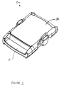
- Figure 1 is a perspective view of a buckle in accordance with the invention comprising releasably coupled male and female members.
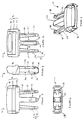
- Figure 2 is a perspective view of the male member in accordance with the invention.
- Figure 3 is a top view of the male-member.
- Figure 4 is a right-side view of the male member.
- Figure 5 is a bottom view of the male member.
- Figure 6 is a front view of the male member.
- Figure 7 is a perspective view of a female member in accordance with the invention.
- Figure 8 is a top view of the female member.
- Figure 9 is right-side view of the female member.
- Figure 10 is a bottom view of the female member.
- Figure 11 is a rear view of the female member.
- Figure 12 is a cross-section view of the female member taken generally along lines 12-12 of Figure 9.
- Figure 13 is a left-side view of the assembled buckle shown in Figure 1.
- Figure 14 is a cross-section view of the buckle taken generally along lines 14-14 of Figure 13.
- Figure 15 is a top view of the buckle showing the coupling arrangement of the internal portions of the male and female members in a dotted outline.
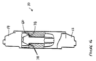
- Figure 16 is a partial cut-away view of the left-side of the buckle also illustrating the coupling arrangement of the male and female members.
- FIG. 1 is a perspective view of a side-release buckle fastener or connector 10 in accordance with the present invention.
- the buckle 10 comprises a plug or male member 12 releasably coupled with a receptacle or female member 14.
- the male and female members 12, 14 preferably comprise molded plastic.
- FIGS 2 to 6 illustrate the male member 12 in greater detail.
- the male member 12 includes a strap-connector base portion 16 comprising two spaced-apart cross members 18, 20 having an opening 22 therebetween.
- a strap, belt or the like may be attached to the base portion 16 by inserting an end of the strap through the opening 22, looping it around the outer cross member 18, and sewing it or otherwise attaching it to the rest of the strap.
- the base portion 16 may also comprise cross-members adapted for adjustably securing a strap or belt.
- a pair of resilient arms 24 extend outwardly from the base portion 16 in a direction generally perpendicular to the cross members 18, 20.
- the arms each include an elongated stem portion 26 and an enlarged portion 28 at the end thereof distal said base portion 16.
- Each of the arm stems 26 includes opposite inner and outer sides 30 32 wherein the inner side 30 of one arm faces the inner side 30 of the other arm.
- the arm stems 26 also include opposite upper and lower sides 34, 36 that connect the inner and outer sides 30, 32.
- Each enlarged portion 28 has the shape of a truncated triangle including two base segments defining upper and lower abutment surfaces 38, 40.
- the abutment surfaces 38, 40 are spaced apart from each other on opposite sides of the stem portion 26 of each arm 24.
- the abutment surfaces 38, 40 substantially face the base portion 16.
- the abutment surfaces 38, 40 also each extend between the inner and outer sides 30, 32 of each arm stem 26.
- the geometric center of each abutment surface is substantially aligned with a longitudinal axis 41 extending through the arm stems 26.
- the male member also includes a center alignment arm 42 to facilitate insertion and alignment of the male member 12 when coupled with the female member 14.
- the center arm 42 extends generally perpendicularly to the cross-members 18, 20 of the base portion 16 and is disposed between the arms 24.
- the free end 44 of the center arm 42 distal to the base portion 16 is tapered to facilitate insertion in the female member 14 as will be described below.
- FIG. 7-12 illustrate the female receptacle member 14 in greater detail.
- the female member 14 comprises a body with a cavity 48 therein adapted for receiving the arms 24 of the male member 12.
- the female member body includes a rear end with an opening 50 therein leading to the cavity 48.
- a cross-member 52 is provided at the opposite front end of the female member body on which the end of a strap, belt or the like (not shown) may be fastened.
- Figure 12 is a cross-section view of the female member 14 taken generally along lines 12-12 of Figure 9, illustrating an upper interior side of the female member.
- the opposite lower interior side of the body, which is integrally formed with the upper side, has a similar design as is apparent from Figure 11.
- a pair of parallel center ridges 54 extend into the cavity 48 defining a channel therebetween on both the upper and lower interior sides.
- the channels are arranged in the body for receiving the center arm 42 of the male member 12 when the male and female members are coupled.
- Each interior side of the body also includes a pair of tapered outer ridges or ramps 56 extending into the cavity 48 as shown in Figures 11 and 12.
- the ramps 56 of each pair are spaced-apart and at opposite sides of the female member body.
- the ramps each include an elongated slide surface 58 facing one of the center ridges 54 at a slight angle and a retaining surface 60 facing the front end of the female member away from the opening 50 of the cavity 48.
- the retaining and slide surfaces 58, 60 of each ramp 56 are connected at a corner 62.
- Each of the four retaining surfaces 60 are adapted to engage one of the abutment surfaces 38 of the male member 12 to provide for a secure coupling of the buckle parts as will be described below.
- the female member body also includes a pair side recesses 64 at opposite sides thereof leading to the interior cavity 48.
- An actuating member 66 is disposed in each of the side recesses 64 for resilient movement therein.
- the actuating members 66 each comprise an elongated arm 68 having one end connected to the female member body, an enlarged grip 70 connected to an opposite end of the arm 68, and an extension member 72 projecting from the grip 70.
- the grip 70 is adapted for being pressed by the user's fingers.
- the extension member 72 includes a tip 74 at the end thereof that projects into the body cavity between two tapered outer ridges 56 (see Figures 11 and 12).
- Each actuating member 66 is adapted to be resiliently moved into one of the side recesses 64 such that the tip 74 of the extension member 72 projects inwardly beyond the corners 62 of the tapered ridges 56. As will be described below, the actuating members, when pressed, enables the male member 12 to be readily disconnected from the female member 14.
- the free ends of the outer and center arms 24, 42 of the male member 12 are first inserted in the opening 50 of the female member body. Initially, the tapered end 44 of the center arm 42 engages the ends of the center ridges 54 in the cavity 48 of the female member body, which has the effect of aligning and centering the male member 12 relative to the female member 14. As the male member 12 is pushed further in the cavity 48, the outer sides 32 of the elongated arms 24 engage the slide surfaces 58 of the ramps 56 in the cavity 48. The ramps 56 are tapered, causing the free ends of the arms 24 of the male member 12 to resiliently flex inwardly toward each other from an originally unstressed configuration.
- each of the two abutment surfaces 38 on each arm 24 directly oppose and are engageable with one of the retaining surfaces 60 in the female member 14 as is apparent from Figure 16. Any attempt to pull apart the coupled male and female members 12, 14 with pull-apart forces without actuation of the actuating members 66 will force the abutment surfaces 38 against the retaining surfaces 60, creating an effective array of resistive forces that directly oppose (at 180°) the pull-apart forces.
- the buckle in accordance with the present invention provides for an extremely secure coupling of the male and female members under heavy loads and guards against unintentional uncoupling.
- the actuating members 66 on each side of the female member are resiliently pressed inwardly toward each other causing the extension member 72 of each actuating member to engage the outer side 32 of each of the arms 24 and to urge the arms 24 inwardly toward each other.
- the abutment surfaces 38 on the arms are thereby moved inwardly relative to the retaining surfaces 60 of the female member 14.
- the abutment surfaces 38 clear the corners 62 of the ramps 56, the abutment and retaining surfaces become disengaged.
- the male member is then thrusted out of the receptacle by resilient forces exerted by the arms 24 against the tapered slide surfaces 58 of the ramps 56.
- the male and female members can thus be quickly and easily separated when desired.
- the spaced-apart configuration of the abutment surfaces 38 on the arms 24 of the male member on opposite sides of the arm stems 26 is also advantageous because it enables the actuating members 66 to engage the arms 24 at any location along the length thereof including at locations on the arm stems 26 for disengagement of the male and female members.
- Buckles in accordance with the present invention can thus have a shorter overall length and be more compact than prior art devices, which by contrast, have only a single elongated abutment surface on each arm and must be pressed by the actuating member at a location between the abutment surface and the free end of each arm.
- the free ends of the arms are substantially enlarged in order to provide an effective surface for engaging the actuating member. Consequently, buckles in accordance with the prior art are substantially longer than those of the present invention.
- buckles in accordance with the present invention can have a smaller width and be more compact than prior art brackets because the presence of the actuating members allows the arms of the male member to be easily engaged even if they are located nearer to the center of the buckle.
Abstract
Description
- The present invention relates generally to two-piece buckle type fasteners and, more particularly, to two-piece side-release buckles.
- Two-piece buckles comprise releasably connectable male and female members. The buckles are typically used to fasten the ends of belts or straps, wherein each of the male and female members is attached to one end of the belt or strap. The buckles have various applications, but are particularly common in sports and camping equipment like backpacks and life jackets.
- The male member of the buckle typically includes a pair of resilient arms that may be inserted and releasably locked in the female member to couple the members. Each arm includes an abutment surface that is releasably engageable with a corresponding retaining surface in the female member to lock the members together. Side-release buckles include recesses at the sides of the female member that expose the arms of the male member such that the male and female members may be uncoupled by pressing the arms of the male member at the side recesses to disengage the abutment and retaining surfaces.
- U.S. Patent Nos. 4,577,377; 4,672,725; and 4,987,661 all issued to Kasai, disclose two-piece side-release buckles wherein the female member includes a pair of external actuating members. The actuating members, when pressed, act against the arms of the male member and cause the abutment and retaining surfaces on the male and female members, respectively, to become disengaged. The actuating members are not connected to the male member and can thus extend outwardly from the buckle, making the buckle easier to uncouple by a user wearing gloves or mittens.
- One problem with known buckles like those described above is that when large loads are applied to the buckles, the arms of the male member tend to flex inwardly, causing the abutment and retaining surfaces to disengage and leading to an inadvertent separation of the male and female members.
- U.S. Patent No. 5,222,279 issued to Frano and U.K. Patent Publication No. 2,262,962 to Fudaki each disclose buckles comprising a male member having arms, portions of which are engageable with the female member. The engageable portions are noted to be located at positions on the arms such that torque at the arms is reduced to lessen the chance of inadvertent separation. In each reference, however, the arms are designed to perform both engagement and disengagement functions; the arms include portions exposed through side openings in the female member that can be pressed to uncouple the parts. Accordingly, the arms in the male member must be widely spaced-apart and located in close proximity with the sides of the female member. The female member must also include ramps and engagement surfaces proximate its sides engageable by the arms. Therefore, brackets in accordance with these prior art references must be substantially wide in order to accommodate the design of the parts therein and cannot be made suitably compact. Another problem with the buckles disclosed in the prior art references is that it is often difficult to uncouple the male and female parts because the arms of the male member must be directly pressed by the user of the buckle and the engaging portions of the arms must be moved a sufficient distance to disengage the parts. The uncoupling process is especially difficult if the user is wearing gloves or mittens.
- An object of the present invention is to provide a two-piece side release buckle that remains securely coupled even when high loads are applied to pull apart the buckle.
- Another object of this invention is to provide a compact two-piece side-release buckle that can be securely coupled.
- A further object of the invention is to provide a two-piece side release buckle that can be readily uncoupled when desired.
- In accordance with the present invention, a two-piece side-release buckle is provided comprising releasably connectable male and female members. The male member includes a strap connector base portion on which a strap or a belt may be attached. The male member also includes two resilient arms extending outwardly from the base portion. The arms each include at a free end distal to the base portion separate upper and lower abutment surfaces. The upper and lower abutment surfaces are discrete and spaced-apart from each other. The female member includes a body with a cavity therein, in which the arms of the male member may be inserted for coupling the male and female members. The body includes retaining surfaces in the cavity that are each adapted for engaging one of the abutment surfaces of the male member when the male and female members are coupled to securely lock the members together. The female member also includes two actuating members that, when pressed, act against the arms and cause the abutment surfaces of each arm to become disengaged from the corresponding retaining surfaces in the body to enable the male and female members to be quickly and easily separated. The female member also includes a strap cross-member on which a strap or belt may be attached at an end thereof distal to the male member.
- Figure 1 is a perspective view of a buckle in accordance with the invention comprising releasably coupled male and female members.
- Figure 2 is a perspective view of the male member in accordance with the invention.
- Figure 3 is a top view of the male-member.
- Figure 4 is a right-side view of the male member.
- Figure 5 is a bottom view of the male member.
- Figure 6 is a front view of the male member.
- Figure 7 is a perspective view of a female member in accordance with the invention.
- Figure 8 is a top view of the female member.
- Figure 9 is right-side view of the female member.
- Figure 10 is a bottom view of the female member.
- Figure 11 is a rear view of the female member.
- Figure 12 is a cross-section view of the female member taken generally along lines 12-12 of Figure 9.
- Figure 13 is a left-side view of the assembled buckle shown in Figure 1.
- Figure 14 is a cross-section view of the buckle taken generally along lines 14-14 of Figure 13.
- Figure 15 is a top view of the buckle showing the coupling arrangement of the internal portions of the male and female members in a dotted outline.
- Figure 16 is a partial cut-away view of the left-side of the buckle also illustrating the coupling arrangement of the male and female members.
- Figure 1 is a perspective view of a side-release buckle fastener or
connector 10 in accordance with the present invention. Thebuckle 10 comprises a plug ormale member 12 releasably coupled with a receptacle orfemale member 14. - While other materials may be used, the male and
female members - Figures 2 to 6 illustrate the
male member 12 in greater detail. Themale member 12 includes a strap-connector base portion 16 comprising two spaced-apartcross members base portion 16 by inserting an end of the strap through theopening 22, looping it around theouter cross member 18, and sewing it or otherwise attaching it to the rest of the strap. Although not shown, thebase portion 16 may also comprise cross-members adapted for adjustably securing a strap or belt. - A pair of
resilient arms 24 extend outwardly from thebase portion 16 in a direction generally perpendicular to thecross members elongated stem portion 26 and an enlargedportion 28 at the end thereof distal saidbase portion 16. Each of thearm stems 26 includes opposite inner andouter sides 30 32 wherein theinner side 30 of one arm faces theinner side 30 of the other arm. The arm stems 26 also include opposite upper andlower sides outer sides - Each enlarged
portion 28 has the shape of a truncated triangle including two base segments defining upper andlower abutment surfaces stem portion 26 of eacharm 24. The abutment surfaces 38, 40 substantially face thebase portion 16. As shown in Figure 2, the abutment surfaces 38, 40 also each extend between the inner andouter sides arm stem 26. The geometric center of each abutment surface is substantially aligned with alongitudinal axis 41 extending through the arm stems 26. - The male member also includes a
center alignment arm 42 to facilitate insertion and alignment of themale member 12 when coupled with thefemale member 14. Thecenter arm 42 extends generally perpendicularly to the cross-members 18, 20 of thebase portion 16 and is disposed between thearms 24. Thefree end 44 of thecenter arm 42 distal to thebase portion 16 is tapered to facilitate insertion in thefemale member 14 as will be described below. - Figure 7-12 illustrate the
female receptacle member 14 in greater detail. Thefemale member 14 comprises a body with acavity 48 therein adapted for receiving thearms 24 of themale member 12. The female member body includes a rear end with anopening 50 therein leading to thecavity 48. A cross-member 52 is provided at the opposite front end of the female member body on which the end of a strap, belt or the like (not shown) may be fastened. - Figure 12 is a cross-section view of the
female member 14 taken generally along lines 12-12 of Figure 9, illustrating an upper interior side of the female member. The opposite lower interior side of the body, which is integrally formed with the upper side, has a similar design as is apparent from Figure 11. A pair ofparallel center ridges 54 extend into thecavity 48 defining a channel therebetween on both the upper and lower interior sides. The channels are arranged in the body for receiving thecenter arm 42 of themale member 12 when the male and female members are coupled. - Each interior side of the body also includes a pair of tapered outer ridges or ramps 56 extending into the
cavity 48 as shown in Figures 11 and 12. Theramps 56 of each pair are spaced-apart and at opposite sides of the female member body. The ramps each include anelongated slide surface 58 facing one of thecenter ridges 54 at a slight angle and a retainingsurface 60 facing the front end of the female member away from theopening 50 of thecavity 48. The retaining and slide surfaces 58, 60 of eachramp 56 are connected at acorner 62. Each of the four retainingsurfaces 60 are adapted to engage one of the abutment surfaces 38 of themale member 12 to provide for a secure coupling of the buckle parts as will be described below. - As shown in Figures 7-10, the female member body also includes a pair side recesses 64 at opposite sides thereof leading to the
interior cavity 48. An actuatingmember 66 is disposed in each of the side recesses 64 for resilient movement therein. Theactuating members 66 each comprise anelongated arm 68 having one end connected to the female member body, anenlarged grip 70 connected to an opposite end of thearm 68, and anextension member 72 projecting from thegrip 70. Thegrip 70 is adapted for being pressed by the user's fingers. Theextension member 72 includes atip 74 at the end thereof that projects into the body cavity between two tapered outer ridges 56 (see Figures 11 and 12). Each actuatingmember 66 is adapted to be resiliently moved into one of the side recesses 64 such that thetip 74 of theextension member 72 projects inwardly beyond thecorners 62 of the taperedridges 56. As will be described below, the actuating members, when pressed, enables themale member 12 to be readily disconnected from thefemale member 14. - To couple the male and
female members center arms male member 12 are first inserted in theopening 50 of the female member body. Initially, thetapered end 44 of thecenter arm 42 engages the ends of thecenter ridges 54 in thecavity 48 of the female member body, which has the effect of aligning and centering themale member 12 relative to thefemale member 14. As themale member 12 is pushed further in thecavity 48, theouter sides 32 of theelongated arms 24 engage the slide surfaces 58 of theramps 56 in thecavity 48. Theramps 56 are tapered, causing the free ends of thearms 24 of themale member 12 to resiliently flex inwardly toward each other from an originally unstressed configuration. Upon further pressing of themale member 12 in thecavity 48, theenlarged portions 28 at the end of the eacharm 24 clear thecorners 62 of theramps 56 and snap outwardly to their original unstressed form (Figures 13-16). In this position, each of the twoabutment surfaces 38 on eacharm 24 directly oppose and are engageable with one of the retaining surfaces 60 in thefemale member 14 as is apparent from Figure 16. Any attempt to pull apart the coupled male andfemale members actuating members 66 will force the abutment surfaces 38 against the retaining surfaces 60, creating an effective array of resistive forces that directly oppose (at 180°) the pull-apart forces. The particular configuration of spaced-apart abutment surfaces on the male member arms permits the abutment surfaces to be aligned with the longitudinal axis of the arms. Thus, the pull-apart forces applied through the arms of the male member substantially coincide with the opposing resistive forces, minimizing formation of torque or moments therefrom that may cause the abutment and retaining surfaces to become disengaged. Accordingly, the buckle in accordance with the present invention provides for an extremely secure coupling of the male and female members under heavy loads and guards against unintentional uncoupling. - To disengage the male and
female members actuating members 66 on each side of the female member are resiliently pressed inwardly toward each other causing theextension member 72 of each actuating member to engage theouter side 32 of each of thearms 24 and to urge thearms 24 inwardly toward each other. The abutment surfaces 38 on the arms are thereby moved inwardly relative to the retaining surfaces 60 of thefemale member 14. When the abutment surfaces 38 clear thecorners 62 of theramps 56, the abutment and retaining surfaces become disengaged. The male member is then thrusted out of the receptacle by resilient forces exerted by thearms 24 against the tapered slide surfaces 58 of theramps 56. The male and female members can thus be quickly and easily separated when desired. - The spaced-apart configuration of the abutment surfaces 38 on the
arms 24 of the male member on opposite sides of the arm stems 26 is also advantageous because it enables theactuating members 66 to engage thearms 24 at any location along the length thereof including at locations on the arm stems 26 for disengagement of the male and female members. Buckles in accordance with the present invention can thus have a shorter overall length and be more compact than prior art devices, which by contrast, have only a single elongated abutment surface on each arm and must be pressed by the actuating member at a location between the abutment surface and the free end of each arm. The free ends of the arms are substantially enlarged in order to provide an effective surface for engaging the actuating member. Consequently, buckles in accordance with the prior art are substantially longer than those of the present invention. - Moreover, buckles in accordance with the present invention can have a smaller width and be more compact than prior art brackets because the presence of the actuating members allows the arms of the male member to be easily engaged even if they are located nearer to the center of the buckle.
- The present invention has been described in the foregoing specification with respect to a specific embodiment that serves as an example to illustrate the invention rather than to limit its scope. Modifications may be made thereto without departing from the broader teachings of the invention.
Claims (18)
- A two-piece buckle, comprising:
a male member (12) including a base portion (16) and two arms (24) extending outwardly therefrom, said arms (24) each including at a free end distal said base portion (16) an upper abutment surface (38) and a lower abutment surface (40) wherein said upper and lower abutment surfaces (38, 40) are discrete and spaced apart from each other; and
a female member (14) including a body with a cavity (48) therein for receiving said arms (24) of said male member (12), said body including a plurality of retaining surfaces (60), each corresponding to one of said abutment surfaces (38, 40) of said male member (12) and adapted for engaging said abutment surface (38, 40) when the male and female members (12, 14) are coupled to resist separation thereof;
characterised in that each arm (24) of said male member (12) includes a longitudinal axis (41) extending therethrough, and for each arm (24) the upper and lower abutment surfaces (38, 40) are located on opposite sides of the longitudinal axis (41) of said arm (24), and wherein the female member (14) includes two actuating members (66), each engageable with one of said arms (24) for disengaging said abutment surfaces (38, 40) from corresponding retaining surfaces (60) and thereby uncoupling the male and female members (12, 14) when desired. - The buckle of claim 1, wherein each of said arms (24) includes opposite inner and outer sides (30, 32) wherein the inner side (30) of one arm (24) faces the inner side (30) of the other arm (24), and wherein the abutment surfaces (38, 40) extend between the inner and outer sides (30, 32) of each arm (24).
- The buckle of claim 2, wherein each of said arms (24) further comprises an upper side (34) and an opposite lower side (36) connecting said inner and outer sides (30, 32) and wherein said upper abutment surface (38) extends upwardly from said upper side (34) and said lower abutment surface (40) extends downwardly from said lower side (36).
- The buckle of claim 1, wherein each said arm (24) includes an enlarged portion (28) at the free end thereof, and wherein said abutment surfaces (38, 40) are located at said enlarged portion (28).
- The buckle of claim 4, wherein said enlarged portion (28) has a truncated triangle shape that includes two spaced apart base segments facing said base portion (16) of said male member (12), and wherein said abutment surfaces (38, 40) are located at said base segments.
- The buckle of claim 1, wherein said abutment surfaces (38, 40) of each arm (24) are each oriented in a plane generally perpendicular to said longitudinal axis (41) of said arm (24).
- The buckle of claim 1, wherein said arms (24) each comprise an elongated arm stem (26) and wherein said upper and lower abutment surfaces (38, 40) are located on opposite sides of said arm stem (26).
- The buckle of claim 1, wherein the male member (12) further comprises a center arm (42) extending outwardly from said base portion (16) and disposed between said two arms (24).
- The buckle of claim 8, wherein the center arm (42) includes a tapered free end (44) distal said base portion (16).
- The buckle of claim 8, wherein the body includes center ridges (54) therein defining a channel adapted for receiving the center arm (42) for facilitating insertion and alignment of the male member (12) when coupled with the female member (14).
- The buckle of claim 1, wherein said base portion (16) includes at least one cross member (18) on which a strap may be attached, and wherein said cross member (18) is oriented generally perpendicular to said arms (24).
- The buckle of claim 1, wherein said body includes two side recesses (64) leading to said cavity (48) and wherein each actuating member (66) is disposed in one of said side recesses (64) for resilient movement therein.
- The buckle of claim 12, wherein each said actuating member (66) includes a stem (68) connected to the body, an enlarged grip (70) connected to said stem (68), and an extension member (72) projecting from said grip (70) toward said cavity (48).
- The buckle of claim 12, wherein the body of the female member (14) includes two pairs of ramps (56) therein, each ramp (56) being proximate one of the side recesses (64) and including a widened end defining one of said retaining surfaces (60).
- The buckle of claim 14, wherein each actuating member (66) is resiliently extendable between two of said ramps (56) and is adapted to engage one of the arms (24) of said male member (12) and to move said arm (24) such that the abutment surfaces (38, 40) of said arm (24) are disengaged from corresponding retaining surfaces (60) of the body.
- The buckle of claim 1, wherein each actuating member (66) is engageable with one of said arms (24) at a location on said arm (24) between said abutment surfaces (38, 40) and said base portion (16).
- The buckle of claim 1, wherein the male and female members (12, 14) each comprise molded plastic.
- The buckle of claim 1, further comprising means for biasing said abutment surfaces (38, 40) of each male member (12) toward corresponding retaining surfaces (60) of said female member (14) when the male and female members (12, 14) are coupled.
Applications Claiming Priority (2)
| Application Number | Priority Date | Filing Date | Title |
|---|---|---|---|
| US286610 | 1994-08-05 | ||
| US08/286,610 US5546642A (en) | 1994-08-05 | 1994-08-05 | Side-release buckle fastener |
Publications (2)
| Publication Number | Publication Date |
|---|---|
| EP0697179A2 true EP0697179A2 (en) | 1996-02-21 |
| EP0697179A3 EP0697179A3 (en) | 1997-02-12 |
Family
ID=23099371
Family Applications (1)
| Application Number | Title | Priority Date | Filing Date |
|---|---|---|---|
| EP95305359A Withdrawn EP0697179A3 (en) | 1994-08-05 | 1995-07-31 | Side-release buckle fastener |
Country Status (4)
| Country | Link |
|---|---|
| US (1) | US5546642A (en) |
| EP (1) | EP0697179A3 (en) |
| JP (1) | JP3049381B2 (en) |
| KR (1) | KR960006823A (en) |
Cited By (4)
| Publication number | Priority date | Publication date | Assignee | Title |
|---|---|---|---|---|
| EP0792666A2 (en) * | 1996-02-23 | 1997-09-03 | TECHNISUB S.p.A. | Adjustable back strap for diving and swimming equipment |
| FR2767457A1 (en) * | 1997-08-19 | 1999-02-26 | Ykk Corp | Fastening clasp for belt or bracelet |
| US6341383B1 (en) | 1996-02-23 | 2002-01-29 | Technisub S.P.A. | Adjustable back strap for diving and swimming equipment |
| ITMI20081444A1 (en) * | 2008-08-01 | 2010-02-02 | Buhel S R L | CLOSING / FIXING GROUP, IN PARTICULAR FOR HELMETS |
Families Citing this family (22)
| Publication number | Priority date | Publication date | Assignee | Title |
|---|---|---|---|---|
| US6299588B1 (en) * | 1995-07-17 | 2001-10-09 | Richard A. Fratrick | Quick release mechanism for orthopedic limb brace |
| US5851194A (en) * | 1995-07-17 | 1998-12-22 | Fratrick; Richard A. | Quick release mechanism for orthopedic limb brace |
| US5974637A (en) * | 1998-12-22 | 1999-11-02 | National Molding Corporation | High strength composite buckle |
| US6446314B1 (en) * | 2000-08-09 | 2002-09-10 | Joseph Anscher | Push release buckle with improved latching capability |
| US7685685B2 (en) * | 2000-09-14 | 2010-03-30 | Paul Giampavolo | Seat belt with child resistant buckle |
| WO2002021956A2 (en) * | 2000-09-14 | 2002-03-21 | Safe-Strap Company, Inc. | Child resistant buckle |
| US7681288B1 (en) | 2000-09-14 | 2010-03-23 | Paul Giampavolo | Structure and material for a child resistant buckle |
| US6618915B2 (en) * | 2001-02-22 | 2003-09-16 | Paul Giampavolo | Seatbelt with child resistant buckle |
| US6711790B2 (en) | 2001-12-06 | 2004-03-30 | Illinois Tool Works Inc. | Buckle device |
| US7597674B2 (en) * | 2002-07-23 | 2009-10-06 | össur hf | Versatile orthopaedic leg mounted walker |
| US7303538B2 (en) * | 2002-07-23 | 2007-12-04 | Ossur Hf | Versatile orthopaedic leg mounted walkers |
| US7600302B2 (en) * | 2006-07-17 | 2009-10-13 | James Michael Dillner | Safety buckle for child seat and the like |
| US8645983B2 (en) | 2007-09-20 | 2014-02-04 | Sony Corporation | System and method for audible channel announce |
| CN102361569B (en) | 2009-03-31 | 2014-05-28 | Ykk株式会社 | Side release buckle |
| JP5458104B2 (en) * | 2009-09-30 | 2014-04-02 | Ykk株式会社 | Side release buckle |
| US20120011640A1 (en) * | 2010-07-13 | 2012-01-19 | Ykk Corporation Of America | Releasable Clips |
| US20120011686A1 (en) * | 2010-07-13 | 2012-01-19 | Ykk Corporation Of America | Releasable Clips |
| CN102379490B (en) * | 2010-08-27 | 2013-12-25 | 明门香港股份有限公司 | Infant safety belt buckle |
| US9159460B2 (en) * | 2011-09-23 | 2015-10-13 | Global Nuclear Fuels—Americas, Llc | Bundle retention clip, fuel assembly including the same, and method of assembling fuel assembly |
| TWI566717B (en) * | 2015-09-18 | 2017-01-21 | 武倢工業有限公司 | Buckle |
| US20190082858A1 (en) * | 2017-09-19 | 2019-03-21 | Lucyann Durant | Child barrier accessory for a mattress |
| US11723440B1 (en) | 2022-04-04 | 2023-08-15 | Duraflex Hong Kong Limited | Buckle with pull ring |
Citations (5)
| Publication number | Priority date | Publication date | Assignee | Title |
|---|---|---|---|---|
| US4577377A (en) | 1983-05-13 | 1986-03-25 | Nippon Notion Kogyo Co., Ltd. | Buckle for straps |
| US4672725A (en) | 1985-06-06 | 1987-06-16 | Yoshida Kogyo K. K. | Snap buckle |
| US4987661A (en) | 1989-05-13 | 1991-01-29 | Yoshida Kogyo K.K. | Snap Buckle |
| US5222279A (en) | 1992-07-27 | 1993-06-29 | Illinois Tool Works Inc. | Buckle having increased holding power when under load |
| GB2262962A (en) | 1991-12-20 | 1993-07-07 | Yoshida Kogyo Kk | Buckle assembly |
Family Cites Families (14)
| Publication number | Priority date | Publication date | Assignee | Title |
|---|---|---|---|---|
| US3251110A (en) * | 1963-09-27 | 1966-05-17 | Watertown Mfg Company | Clasp |
| US3798711A (en) * | 1972-06-26 | 1974-03-26 | S Cousins | Separable fastener |
| US3967351A (en) * | 1975-04-18 | 1976-07-06 | Melvin Rosenberg | Clasp |
| US4035877A (en) * | 1975-09-15 | 1977-07-19 | Brownson Ivan F | Buckle |
| US4150464A (en) * | 1977-08-10 | 1979-04-24 | Illinois Tool Works Inc. | Buckle |
| US4171555A (en) * | 1978-05-01 | 1979-10-23 | Illinois Tool Works Inc. | Buckle |
| DE8120432U1 (en) * | 1981-07-13 | 1981-12-24 | Fildan, Gerhard, Ing.(Grad.), 7250 Leonberg | CLOSURE, ESPECIALLY FOR CLOTHING, BELTS AND THE LIKE |
| SE447696B (en) * | 1982-09-20 | 1986-12-08 | Fixfabriken Ab | CONSISTING OF TRADE AND HUNDRED STICKLAS |
| DE8512710U1 (en) * | 1985-04-30 | 1985-06-13 | Fildan, Gerhard, Ing.(Grad.), 7250 Leonberg | Separable lock |
| JPH0130090Y2 (en) * | 1985-06-06 | 1989-09-13 | ||
| US4688337A (en) * | 1985-12-20 | 1987-08-25 | National Molding Corporation | Buckle type fastener |
| IT220555Z2 (en) * | 1990-07-10 | 1993-10-04 | Itw Fastex Italia Spa | TWO ELEMENTS RELEASABLE BUCKLE |
| JPH06118U (en) * | 1992-06-15 | 1994-01-11 | 吉田工業株式会社 | buckle |
| JPH0652518U (en) * | 1992-12-25 | 1994-07-19 | 吉田工業株式会社 | buckle |
-
1994
- 1994-08-05 US US08/286,610 patent/US5546642A/en not_active Expired - Lifetime
-
1995
- 1995-07-31 EP EP95305359A patent/EP0697179A3/en not_active Withdrawn
- 1995-08-03 JP JP7198434A patent/JP3049381B2/en not_active Expired - Fee Related
- 1995-08-04 KR KR1019950024064A patent/KR960006823A/en not_active Application Discontinuation
Patent Citations (5)
| Publication number | Priority date | Publication date | Assignee | Title |
|---|---|---|---|---|
| US4577377A (en) | 1983-05-13 | 1986-03-25 | Nippon Notion Kogyo Co., Ltd. | Buckle for straps |
| US4672725A (en) | 1985-06-06 | 1987-06-16 | Yoshida Kogyo K. K. | Snap buckle |
| US4987661A (en) | 1989-05-13 | 1991-01-29 | Yoshida Kogyo K.K. | Snap Buckle |
| GB2262962A (en) | 1991-12-20 | 1993-07-07 | Yoshida Kogyo Kk | Buckle assembly |
| US5222279A (en) | 1992-07-27 | 1993-06-29 | Illinois Tool Works Inc. | Buckle having increased holding power when under load |
Cited By (6)
| Publication number | Priority date | Publication date | Assignee | Title |
|---|---|---|---|---|
| EP0792666A2 (en) * | 1996-02-23 | 1997-09-03 | TECHNISUB S.p.A. | Adjustable back strap for diving and swimming equipment |
| EP0792666A3 (en) * | 1996-02-23 | 1997-09-10 | TECHNISUB S.p.A. | Adjustable back strap for diving and swimming equipment |
| US6341383B1 (en) | 1996-02-23 | 2002-01-29 | Technisub S.P.A. | Adjustable back strap for diving and swimming equipment |
| FR2767457A1 (en) * | 1997-08-19 | 1999-02-26 | Ykk Corp | Fastening clasp for belt or bracelet |
| US5953798A (en) * | 1997-08-19 | 1999-09-21 | Ykk Corporation | Buckle |
| ITMI20081444A1 (en) * | 2008-08-01 | 2010-02-02 | Buhel S R L | CLOSING / FIXING GROUP, IN PARTICULAR FOR HELMETS |
Also Published As
| Publication number | Publication date |
|---|---|
| JP3049381B2 (en) | 2000-06-05 |
| JPH0856710A (en) | 1996-03-05 |
| US5546642A (en) | 1996-08-20 |
| KR960006823A (en) | 1996-03-22 |
| EP0697179A3 (en) | 1997-02-12 |
Similar Documents
| Publication | Publication Date | Title |
|---|---|---|
| US5546642A (en) | Side-release buckle fastener | |
| US5419020A (en) | Separable buckle | |
| US5222279A (en) | Buckle having increased holding power when under load | |
| US4866819A (en) | Buckle assembly | |
| US4688337A (en) | Buckle type fastener | |
| US4672725A (en) | Snap buckle | |
| US6052875A (en) | Buckle assembly | |
| US5027481A (en) | Shell buckle | |
| US5735024A (en) | Fastening mechanism for connecting articles and the like together | |
| US5507076A (en) | Side-release buckle having improved locking feature | |
| US4577377A (en) | Buckle for straps | |
| EP1011362B1 (en) | Interlocking device | |
| EP0681793B1 (en) | Buckle which is releasable by depression of a hinged member | |
| EP0535606B1 (en) | Buckle | |
| EP1591045B1 (en) | Buckle and baby carrier using the same | |
| GB2150632A (en) | Buckles | |
| US10702025B1 (en) | Buckle | |
| US4813110A (en) | Snap connector, lever | |
| EP0044639B1 (en) | A buckle for belts or the like | |
| US5197164A (en) | Quick release strap connector | |
| GB2176832A (en) | Fastener device for use on garments | |
| GB2099494A (en) | Improvements in and relating to buckles | |
| US20230404219A1 (en) | Buckle | |
| CN117122131A (en) | Belt buckle | |
| WO2002080721A1 (en) | Buckle |
Legal Events
| Date | Code | Title | Description |
|---|---|---|---|
| PUAI | Public reference made under article 153(3) epc to a published international application that has entered the european phase |
Free format text: ORIGINAL CODE: 0009012 |
|
| AK | Designated contracting states |
Kind code of ref document: A2 Designated state(s): DE FR GB IT |
|
| PUAL | Search report despatched |
Free format text: ORIGINAL CODE: 0009013 |
|
| AK | Designated contracting states |
Kind code of ref document: A3 Designated state(s): DE FR GB IT |
|
| 17P | Request for examination filed |
Effective date: 19970326 |
|
| 17Q | First examination report despatched |
Effective date: 19990223 |
|
| STAA | Information on the status of an ep patent application or granted ep patent |
Free format text: STATUS: THE APPLICATION IS DEEMED TO BE WITHDRAWN |
|
| 18D | Application deemed to be withdrawn |
Effective date: 19990706 |