EP0700697A1 - Ski with a system for influencing its stiffness by using friction - Google Patents
Ski with a system for influencing its stiffness by using friction Download PDFInfo
- Publication number
- EP0700697A1 EP0700697A1 EP95117217A EP95117217A EP0700697A1 EP 0700697 A1 EP0700697 A1 EP 0700697A1 EP 95117217 A EP95117217 A EP 95117217A EP 95117217 A EP95117217 A EP 95117217A EP 0700697 A1 EP0700697 A1 EP 0700697A1
- Authority
- EP
- European Patent Office
- Prior art keywords
- ski
- plate
- stop
- stiffness
- support plate
- Prior art date
- Legal status (The legal status is an assumption and is not a legal conclusion. Google has not performed a legal analysis and makes no representation as to the accuracy of the status listed.)
- Granted
Links
Images


Classifications
-
- A—HUMAN NECESSITIES
- A63—SPORTS; GAMES; AMUSEMENTS
- A63C—SKATES; SKIS; ROLLER SKATES; DESIGN OR LAYOUT OF COURTS, RINKS OR THE LIKE
- A63C9/00—Ski bindings
- A63C9/003—Non-swivel sole plate fixed on the ski
-
- A—HUMAN NECESSITIES
- A63—SPORTS; GAMES; AMUSEMENTS
- A63C—SKATES; SKIS; ROLLER SKATES; DESIGN OR LAYOUT OF COURTS, RINKS OR THE LIKE
- A63C5/00—Skis or snowboards
- A63C5/06—Skis or snowboards with special devices thereon, e.g. steering devices
- A63C5/07—Skis or snowboards with special devices thereon, e.g. steering devices comprising means for adjusting stiffness
-
- A—HUMAN NECESSITIES
- A63—SPORTS; GAMES; AMUSEMENTS
- A63C—SKATES; SKIS; ROLLER SKATES; DESIGN OR LAYOUT OF COURTS, RINKS OR THE LIKE
- A63C9/00—Ski bindings
-
- A—HUMAN NECESSITIES
- A63—SPORTS; GAMES; AMUSEMENTS
- A63C—SKATES; SKIS; ROLLER SKATES; DESIGN OR LAYOUT OF COURTS, RINKS OR THE LIKE
- A63C9/00—Ski bindings
- A63C9/005—Ski bindings with means for adjusting the position of a shoe holder or of the complete binding relative to the ski
Landscapes
- Footwear And Its Accessory, Manufacturing Method And Apparatuses (AREA)
- Seats For Vehicles (AREA)
- Chair Legs, Seat Parts, And Backrests (AREA)
- Vibration Prevention Devices (AREA)
Abstract
Description
- The invention relates to a ski provided with a system for influencing the stiffness of an area of the ski, especially the underfoot, this system comprising an elongated support means arranged in longitudinal direction of the ski, a first portion of said support means fixed to the ski and a free end portion being movable in relation to the ski in longitudinal direction thereof, and an impedance means cooperating with said support means.
- A ski provided with such system is disclosed in EP-A 04 09 749 referring to a plate called Rossi-Bar which is slidably guided in longitudinal direction of the ski. The front and rear ends of said plate are engaged by spring means formed of elastomeric material and supported on the ski. The stiffness of the ski must be unavoidably increased under every condition, because the spring means exert a progressive force counteracting against flexing of the ski.
- An additional stiffness is caused by the fact, that the plate, which has the form of a rigid bar, is locked to the ski by clamps along the length of the plate, and it is the clamps which prevent the plate from sliding on the ski upon bending of the ski. Thus the plate reduces the bending of the ski.
- Important conditions affecting downhill skiers are the nature of the snow, the type of skiing to be done, the type of skis and bindings used and the skill of the skier. The snow and the ski run can vary during a day, while the ski and the skier are generally invariable. The snow can range from ice hard snow to very loose or soft snow, sometimes called powder snow. There are profound differences in skiing turns and speed according to the type of snow being skied upon. One primary characteristic of an ski is its ability to bend or flex as it carries a skier. A ski flexes and counterflexes, and keeps the skier in control as he or she follows the contour of a slope and enables a skier to manipulate the skis as he or she bounds and rebounds down the slope. In racing events, the snow can be ice hard both to increase the skier's speed and to avoid ruts in the snow. Hard snow may limit the bending of the skis. Turning is mainly accomplished in hard snow by the skier tilting the skis to dig the edges at the bottom of the ski into the snow by shifting his or her weight and body position. On the other hand, the ski can bend a large amount in powder snow. The longitudinal sides of skis are convex arcs, and it is through the use of the side cuts and bending of the ski that the skier turns; the edges of the skis are of much less importance in turning in powder snow. Regular snow, that is snow whose texture and packing is between hard snow and powder snow, presents other problems to the skier. Experience, communications with racers and other skiing experts, and testing, indicate that a ski stiffer underfoot of the ski boot may be preferable in very hard snow conditions while an overall more flexible ski appears to be preferable in soft snow conditions. An intermediate situation is preferable for snow of intermediate softness. It is also known that a ski loosely attached to the skier transfers little energy from the ski to the skier when the ski encounters obstacles, thus resulting in higher speed. However, a loose attachment results in loss of ski control in turns; hence it is desirable to have a loosely connected ski when traveling essentially in a straight line for greater speed and a tightly connected ski when making turns for greater control.
- The vibration characteristics of skis are also believed to be important. Skis have several vibration modes which are exhibited during skiing. High frequency vibrations break the contact between the ski bearing surface and the snow, which improves speed. On very hard snow conditions, the breaking of the contact between running surface and snow does not result in the same level of benefit but the ski still vibrates resulting in audible and perceptible chatter. A reduction in chatter is desirable in these condicions. Thus different requirements in underfoot stiffness and vibration exist depending on snow conditions. The ski designer, faced with the different kinds of snow, the different types of skiing, and variations in skiers and their bindings, can only develop skis which can handle all of these varying characteristics reasonably well but are not optimized for any specific condition.
- All ski bindings have an effect on ski stiffness underfoot. When a ski bends during skiing, the distance between the toe piece and the heel piece varies since they move relative to each other with the upward curvature of the ski. However, the length of the ski boot sole remains constant. Therefore, there is generally a limited movement rearwardly of the heelpiece in a clamp on the ski to keep it in contact with the boot. The force required to move the heel unit back results in a stiffening of the ski section directly under the bindung and boot. It is believed that most ski bindings on the market fall into this category. Therefore ski manufacturers take this stiffening action of the binding system into consideration in the design of the ski. The underfoot stiffness of the ski bindung combination is thus optimized for the type of skier and preferred snow conditions the ski was intended for. Different binding systems and separate devices to be used in conjunction with the ski and commercially available bindings have been manufactured to either increase or decrease the underfoot stiffness of the basic bindung/ski configuration. Other devices can effect the normal vibration of an ski. Combinations which decrease stiffness underfoot may improve soft snow skiablility while deteriorating skiability towards the end of the hard snow spectrum. Combinations which increase stiffness have the opposite effect.
- In some systems, the binding is constructed to render the ski more flexible. In the ESS v.a.r. device, a boot support plate having a forward portion which is slidable in an channel on the ski, should render the ski more flexible. However, the support plate is fixed with additional fastening means to the ski, and thus is believed to limit its benefits on soft snow. The fixing of the support plate decreases the bending of the ski.
- The Tyrolia Freeflex system utilizes a flexible plate attached to the top of the ski. The plate is fixed to the ski at the toe of the binding and is held in place about the heel by a slidable clamp fixed on the ski. Both toe and heel binding units are affixed on the boot support plate. When the ski bends, the heel clamp moves closer to the toe unit but the flexible plate is allowed to slide rearwardly reducing the tendency of the heel unit to move towards the toe as in a normal binding configuration. The ski is thus allowed to flex more underfoot. The plate is allowed to move in the slidable clamp but is also held to the ski by an additional sliding point between the toe and the heel. This mounting configuration increases sliding friction and thus the overall decrease of ski stiffening is relatively small. Devices of this nature are disclosed in U.S. Patent 3 937 481.
- Most ski binding manufacturers produce bindings which increase the stiffness of skis. The stiffness of an ski provides a firm edge to drive into the snow for making turns in hard or intermediate snow. In this respect, it is much like an ice skater who drives his or her blade into the ice to make a turn. A flexible blade would detract from the skater making a turn, just as a very soft ski in the section directly below the boot would detract from the skier turning in hard snow.
- Some expert skiers performing giant slalom or super giant slalom have found that their turning ability is enhanced when they attach to the ski, such as by gluing, a thin plate on top of the ski in the binding area. This added plate increases the distance between the skier's boot and the edges of the ski, and enhances the leverage which the skier has to drive the edges of the ski into the snow.
- WIPO Document 83/03360 discloses a device wherein glue and an elastomeric material hold a plate for supporting a toe piece and heel piece to the ski. The elastomeric material absorbs some of the vibration of the ski on the hard snow and relieves some of the discomforting noise of the ski rapidly smacking against the snow. Furthermore, the device stiffens the ski/plate/binding combination in the underfoot area of the ski improving edge control on hard snow.
- In U.S. Patent 3 937 481 mentioned earlier, a ski binding having an elongated plate is slidably mounted thereon for cushioning the skier when a forward abutment is encountered. Only the forward or toe portion of the system is fixed to the ski, so that the plate allegedly follows the bending of the ski. The device in fact impedes the bending of the ski since it is strapped to the ski in a number of places. A similar device with similar shortcomings is disclosed in Austrian Patent 373 786. A device of this type is sold under the name Derbyflex.
- It has been believed by many experts that raising the ski binding with such a plate detracts from the skier's ability to control the ski, since it was thought hat the skier had to be close to the snow to "feel" the snow and ski accordingly. The present inventors and other manufacturers believe that this notion is wrong for most types of skiers, and that holding a ski boot somewhat high over the ski increases his or her ability to control the ski.
- Other patents disclosing ski bindings for increasing stiffness in skis include German Patent 21 35 450.
- Even though the added plate is beneficial, it only applies to skiing on hard snow where a stiffer underfoot ski is desirable. When used on softer or powder snow, the added stiffness detracts from the skier's ability to control the ski since easier bending adds to the turnability of the ski in soft snow.
- Other devices are known having moveable boot support plates on skis. For example, U.S. Patent 4 974 867 discloses a shock absorbing buffer disposed between a ski and a bindung, and is not really related to the stiffness of the binding.
- The skill of the skier is another condition which the skiing apparatus should take into consideration. Although stiff skis are beneficial to good skiers in events such as giant slalom and super giant slalom, novice skiers should generally use flexible skis for all events, since they enable reasonable performance even though edge control in turns may be sacrificed.
- The inventors are unaware of any skibindings or skis which are adaptable to vary the stiffness in the binding location of a ski system according to the nature of the snow or the type of skiing to be done. They are aware of no skiing system whose stiffness and vibration characteristics can be changed to perform well in the various skiing conditions.
- It is an object of the invention to provide an improved device for controlling snow skis according to the nature of the snow, the skiing to be done, the type of skis and/or the skill oft the skier.
- Another aspect of the invention is to provide a support plate for a ski binding which controls the stiffness of skis in different skiing conditions.
- A further object of the invention is to provide a device for controlling the stiffness of skis incorporating a plate fixable to a ski and having a slidable portion, and an impedance device for controlling the slidable device to obtain the desired stiffness.
- Another object of the invention is to provide a support plate assembly for controlling the stiffness of a ski with the assembly having a plate attached to the ski and an adjustable stop whose position controls the effects of the plate an the amount of bending of the ski.
- A more particular object of the invention is to provide a support plate and an adjustable stop, the adjustable stop movable to make the device very stiff such as for hard snow, very loose so that the ski can bend such as for soft snow, and at an intermediate position so that the plate can be free when going straight, and be stiffer underfoot in turns.
- It is a further object of the invention to provide a continuously adjustable stiffness device for a ski.
- It is a general object of the present invention to provide an improved ski control system for use with various types of snow, different degrees of skill of the skier, and different skiing events, which system is efficient to manufacture and to use.
- It is yet another object of the invention to provide improved dampening means, to approve the skier's control during vibrations of the ski.
- The invention is characterized in that said impedance means comprises means for accomplishing friction between said free end portion and an member or step attached to the ski, whereby the stiffness of the ski is influenced by friction.
- Said member or stop is preferably adjustable.
- According to a preferred embodiment both the free end portion and the adjusting member have inclined faces for cooperation of the free end portion and the adjusting member, the one inclined faces adapted for being urged between the other inclined faces upon bending of the ski, thereby creating a progresive force upon intruding of the one inclined faces between the other inclined faces.
- In fundamental form, the invention includes an engagement member which is fixable at one location to the ski, and an impedance means which effectively engages the engagement member to change movement of the non-fixed or free portion of the engagement member as bending moments are applied to the ski.
- In its preferred form, the engagement member could be a support plate which supports a ski boot and runs substantially along the length of a ski boot and is attached to the ski. The plate is fixed to the ski at or near one of its ends. The other end of the plate is a free portion which slides longitudinally relative to the ski as the ski flexes or bends longitudinally about an axis or axes tranverse to the longitudinal direction of the ski.
- An adjustable stop can be provided for selectively engaging the free portion of the plate to limit the relative movement of the plate on the ski.
- When the adjustable stop engages the plate, the stop and plate act as an integral unit, and essentially preclude further sliding of the plate, so that the ski cannot bend under the stop and plate. If the adjustable stop is moved away from the plate so that the plate cannot touch the stop, the plate becomes slidable relative to the ski as the ski bends. The adjustable stop can be moved to an intermediate position so that the plate can engage the stop only during turns where the ski bends beyond a determined amount, at which point the plate and stop become a stiffening member to preclude further bending of the ski at the plate and stop. As the ski unbends or before such bending occurs, there is a space between the stop and the plate so that the plate allows substantial bending of the ski.
- With respect to the foregoing discussion, it is an aspect of a preferred embodiment of the invention that the plate is fixed at an end thereof, so that the other end of the plate is mounted for sliding relative to the ski, such as between lower and upper clamps or guides between which the plate can slide as the ski bends. An adjustable stop is provided near the free end. The adjustable stop can be moved between positions where it engages the plate, is totally disengaged from the ski plate or is at an intermediate position where it can engage or not engage the free end of the ski plate according to the bending of the ski. The stop can be in different forms according to the various embodiments of the invention. It is possible that the plate be fixed on the ski and that the stop be slidable relative to the ski, with the same feature of controlling the stiffness of the ski as described above.
- According to a preferred embodiment the support plate includes an elongated main member, and a slide member which can be moved longitudinally on the main member to accommodate ski boots of different sizes. The rear or heel end of the main member is fixed to the ski, and the forward end of the main member has a bearing for the slide. At the forward end of the main member and slide member is an adjustable stop, which in this case is a disc cam. The disc cam is rotatable about an axis which is fixable to the ski. The disc cam has a set of surfaces which can be adjustably juxtapositioned to a forwardly facing surface on the slide member to control the amount in which the slide member and thus the support plate can slide on the ski, to thus control the bending or flexing of the ski.
- The invention will be better understood when reference is had to the following drawings in which like numbers refer to like parts, and in which:
- FIG. 1
- is a schematic drawing of a form of the invention where the impedance means is a contiuously varible bias device including a friction member,
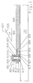
- FIG. 2
- is an exploded isometric view of a support plate assembly of the invention mounted on a portion of a ski, with the cover plate displaced from the assembly to make the components of the assembly more straightforward,
- FIG. 3
- is an plan view of the support assembly of FIG. 2 without a cover plate,
- FIG. 4
- is a cross-section of the support assembly of the invention along the line IV-IV of FIG. 3, and
- FIG. 5
- is a cross section of the support assembly along lines V-V in FIG. 3.
- The invention is directed to the changing of the stiffness of an ski. It includes an engagement means which moves relative to the ski as the ski bends, and an impedance means which cooperates with the engagement means. In some forms of the invention, the engagement means is a plate fixed to the ski, and the impedance means is a stop for engaging the plate to change - in this case increase - the stiffness of the ski. The engagement means and the impedance means can be positioned at different places on the ski to control the stiffness at different areas of the ski. However, in its preferred embodiment, the engagement means is a support plate for supporting the ski boot on the ski, and the impedance means is an adjustable stop for engaging the support plate to vary the underfoot stiffness of the ski. The following discussion relates to various schematic drawings of different embodiments, and to a detailed of one apparatus.
- Referring to FIG. 1, a
stiffness controlling assembly 601 is shown including asupport plate 603 which is fixed to theski 107 at one end, here the rear end of the plate, and is free at ist opposite end, which shown here is theforward end 605. When theski 107 flexes or bends longitudinally about an axis traverse to the longitudinal direction of theski 107, theend 605 slides longitudinally relative to theski 107. - The
free end 605 has tapered portions at the upper and lower part ofplate 603 with inclined faces shown at 607 and 609, which run transverse to ski 107. An adjustment, control orretainer member 611 has ahousing 612 which is attached to the ski by means of a fastener such asscrew 613 and a holdingmember 615, which is attached to the ski, for receiving retainer orfastening member 613 through abore 617 contoured to receive the fastener. A spring such ashelical spring 619 is disposed inhousing 612 and is located to be compressed by compression member such aswasher 621 asfastener 613 is rotated.Spring 619 is compressible betweenshoulder 622 inhousing 612 andmember 621. -
Retainer member 611 includes aflange 623 which extends rearwardly, and has aninclined abutment face 625 which is contoured to engage theface 607 ofplate 603. Holdingmember 615 also has aflange 627 extending partly along the length ofski 107, and having an inclined portion with aface 629 contoured to engage theface 609 ofplate 603. -
Screw 613 has aflange 631 which is seated beneath the upper end wall ofhousing 612 ofadjustment member 611, and has ahead 633 which can be turned to either movenut 621 into holdingmember 615 to compressspring 619, or to be urged in the opposite direction to relieve the compression onspring 619. - The stiffening in the apparatus shown in FIG. 1 is accomplished by friction between an adjusting member and a support plate. The apparatus is continuously adjustable.
- Therefore, in the operation of assembly in FIG. 1, if further stiffening of the ski is desired,
screw 613 is tightened to movenut 621 towards the ski to compressspring 619. This compression urges adjustingmember 611, and the face ofleg 623 againstface 625 ofplate 603. The tension created byface 607 andface 625, and face 609 andface 629, essentially clampsplate 603 to the ski at itsforward end 605, to substantially prevent bending ofski 107 betweenfastener 611 and the anchor between the support plate and the ski. In its most compressed condition, the ski apparatus is extremely stiff underfoot, and is particularly useful in curves made on hard snow. Asfastener 613 is loosened, the compression onspring 619 decreases, and the tension onend 605 ofsupport plate 603 becomes less and less. In its compressed condition, the portion ofski 107 undersupport plate 603 is essentially bendable, and is particularly useful for skiing on loose or powder snow. - There is no need for a clamp to guide
support plate 603 alongski 107 as the ski bends, since the forward end of the plate is confined between theretainer 611 and the holdingmember 615. Thefriction device 601 has some useful features. First, the spring is a progressive force, the spring force increasing as the support plate intrudes between theretainer 611 and the holdingmember 615, increasing stiffness as the ski bends. Second, the spring provides greater friction for flexing than for counterflexing. However, the friction approaches 0 as the angle α approaches 0. - FIG. 2 is an exploded isometric view of a support assembly of a preferred embodiment of the invention mounted on a portion of a
ski 107. As shown, the support assembly comprises a support plate main member, generally 904, and a support plate slide member, generally 905. Themain member 904 and its attachedslide member 905, may from time-to-time be referred to as the support plate. Therearward end 903 of the support platemain member 904 is somewhat thicker than the rest of the main member allowing the forward portion of the main member to be spaced from theunderlying ski 107. The rearward end of the support plate main member is provided withscrew holes 902 for purposes of mounting the main member to the ski and to permit the heel portion of a ski binding to be mounted on the support plate. - The support plate
main member 904 is connected to the supportplate slide member 905, and to the cover plate, generally 906, by means of attachment screws, not shown, which pass throughscrew holes 911 and which are threaded into threadedbushings 908 attached to slidemember 905. - As will be seen, the end of the support plate
main member 904 opposite therearward end 903 has a bifurcated, forked configuration withslots 910 in each of the forks and with a slot 933 positioned between the forks extending into the main member. The attachment screws referred to hold the support platemain member 904 securcly to the supportplate slide member 905, minimizing longitudinal movement between the two. However, in a preferred embodiment of the invention, a ribbed surface is provided at the interface between the two members, and in an especially embodiment, an intermediate layer, for example, an elastomeric material, such as ebonite, is positioned as an intermediate layer between the main member and the slide member. Such a layer not only serves to assure that no longitudinal movement between the two members will occur, but provides an additional advantage in that it tends to dampen vibrations transmitted from the ski to the binding. - In the embodiment shown, the support
plate slide member 905 is tapered toward the front, culminating in anabutment member 931 which serves to engage a peripheral edge of acontrol cam disc 920 which serves as an adjustment member or adjustment stop, as will be explained in more detail in the following. The cam disc can be pivoted about a smooth shanked fastener orspecial purpose screw 909 to juxtapose different peripheral surface toabutment member 931 thereby controlling the amount of bending or flexure of the ski, as will also be explained in more detail hereinafter. A head orcam setting lever 930 is employed to position the cam disc as desired, whileresilient lugs - A portion of the support assembly, together with the cam disc and other associated structure are positioned between a
base plate 913 havinglateral edges cover plate 906, which together serve to form a protective housing for parts of the mechanism. The forward ends of the base plate act as a guide for the pivoting movement of thecam disc 920, as will be better seen in FIG. 4 (FIGS. 3 to 5 are enlarged from that of FIG. 2 for the purpose of clarity).Slot 912 in thecover plate 906 accommodates movement of the forward end of the support plate which occurs during flexure of the ski. - While the back end of the support plate, specially the rearward end of the support plate
main member 903, is fixed to the ski and thus immovable, the forward end of the plate, namely theslide member portion 905, which is supported by a slide bearing yoke, better seen in the other figures, is free to move backward and forward, relative to the surface of the ski, thereby accommodating its flexing. Thecam disc 920, in conjunction withabutment member 931 serves to control the degree of permissible movement, thereby providing a means to control the degree of flexure of stiffness which the ski is capable of experiencing. - FIG. 3 is a plan view of the support plate of FIG. 2, however, with the cover plate removed in the interest of clarity. The figure shows the bifurcated forked configuration of support plate
main member 904 and its attachment to supportplate slide member 905 by means of attachment screws 907 inserted into the threadedbushings 908 extending through forkedslots 910, the bushings forming a part of the support plate slide member. Attachment screws 907, which fasten the main member to the slide member, are better seen in FIG. 5. - The support
plate slide member 905 is retained inslide bearing yoke 918, but is free to move or slide back and forth therein. As stated, the forward part of the slide member tapers to form a projectingabutment member 931 which is juxtaposed to selected peripheral sections ofcam disc 920. Depending upon the clearance between theabutment 931 and the peripheral section, the cam disc either prevents, limits, or allows the essentially uncontrolled longitudinal movement of the forward end of the support plate. - As illustrated in FIG. 3, the
abutment member 931 is juxtaposed to a slightly recessedperipheral section 922 ofcam disc 920, thereby allowing some degree of forward movement of the abutment to accommodate flexure or bending of the ski. Should the cam disc be rotated counterclockwise to bring the recessedperipheral section 923 opposite the abutment, substantially unlimited forward travel of the abutment would be possible. However, were the cam disc to be pivoted in a clockwise direction to bring theouter periphery 921 in juxtaposition withabutment 931, essentially no movement of the slide member would be possible, in which case the support plate would act as a stiffening brace for the ski, particularly desirable where a large amount of stiffness is required, for example, during turns on hard snow. The cam disc is moved to its desired position by manipulation ofcam setting lever 930. It will be seen that the resilient detents or lugs 924 and 925 engagedetent recesses detent projections forward portion 917 of the base plate. While a cam disc with a periphery having distinct "steps" of different radii has been described, it is also possible for the cam disc to have a periphery whose radius varies in a continuous manner. - FIG. 4 is a cross-section of a support plate of the invention along line IV-IV of FIG. 3. In this figure, the front jaw of the safety ski binding can be seen attached to the
cover plate 906 and to the support plate main member and support slide member, 904 and 905 respectively. The figure also shows a ski boot in phantom positioned in the bindung. Illustrated in FIG. 4 is thebase plate 913 including itsfront portion 917 and asetback portion 916, which together with the lower portion of the base plate form an opening through which thecam setting lever 930 projects for easy access. A smooth shanked fastener in the form of ascrew 909 serves the multiple functions of fastening the base plate to the ski, of serving as a pivot point for the cam disc, and to prevent any lifting or lateral movement of the forward part of the ski binding's front jaw. As previously indicated, thepivot fastener slot 912 accommodates the back and forth movement of the cover plate, which it will be remembered is attached to the main member and slide members of the support plate during flexure of the ski. - Referring again to FIG. 3, a useful feature of the invention, whose function is better seen in FIG. 4, is to be found in the positioning of an elastomeric pad or
plate 932 between a portion of the peripheral edge surface of thecam disc 920, and a surface ofabutment member 931. As shown, the positioning of the pad can be accomplished by attaching it to the cam disc by pins located on the cam disc, over which the pad is secured by means of holes located in the latter. As is seen particularly clearly in FIG. 4, before theabutment member 931 can make contact with the peripheral edge of thecam disc 920, it must compress the elastomeric pad. The resistance of the pad to such compression exerts a desirable dampening affect which resists flexing of the ski to a degree determined by the resiliency of the pad. The pad may be disposed over one or more of the recessed peripheral sections of the cam disc to obtain the dampening function described. - FIG. 5 is a cross-section of the support plate along lineV-V of FIG. 2 showing details of the sliding support, which alows the support plate of the invention to accommodate flexure of the ski.
- FIG. 5 shows the manner in which the support
plate slide member 905 is retained by a U-shapedslide bearing yoke 918, the latter being fastenable to a ski by means of fastening screws 919. The support platemain member 904, together withcover plate 906, is fastened to supportplate slide member 905 by means of attachment screws 907 which extend into threadedbushings 908 forming a part of the slide member. The lateral edges 914 and 915, respectively, of the base plate enclose theslide bearing yoke 918, and their upper ends are offset inwardly at the top to function as guide rails for thecover plate 906 so that the cover plate, together with the front jaw may slide during ski flexure in relation to the base plate along the longitudinal axis of the ski. As is clear from the figure, the lateral edges of the base plate, in conjunction with the cover plate, form a housing about a portion of the support plate assembly, protecting the parts thereof from damage and dirt which might otherwise be adventitiously introduced. - As shown in FIG. 4 and FIG. 5, the attachment screws 907 and 919 are positioned coaxially to each other. This is of considerable advantage since it makes it possible to employ the same drilling template for locating the support plate attachment holes in the ski, as is used for installing the safety ski binding screws.
- In installing the support plate of the invention, the slide bearing yoke is first screwed to the ski. The support
plate slide member 905 is thereafter inserted into the yoke, and the base plate is placed thereon and positioned as desired. Thereafter, therear end 903 of the support plate main member with the heel part thereon is fastened to the ski. - The forked
slots 910 in the support platemain member 904, which have the threadedbushings 908 of theslide member 905 fitted therethrough, allow the positioning ofmain member 904 to slidemember 905 to accommodate whatever length of ski boot is to be used in the ski binding. In this connection, boot adjustment slot 933 is provided to accomommodate the shank portion offastener 909 in instances where the ski boot sole is extremely short. - After placement of the support plate
main member 904, thecover plate 906 is placed in position andsmooth shank fastener 909 screwed into the ski. The front jaw is then placed on the cover plate in position and attachment screws 907 are screwed into the threadedbushings 908, simultaneously connecting support platemain member 904 to slidemember 905, preventing their longitudinal movement relative to each other. - With the support plate of the invention installed as described, the
cam disc 920 is adjusted to the position desired. In regard to such adjustment, as long as the supportplate slide part 905 is free to slide in theslide bearing yoke 918, there will be no stressing of the ski, which will be free to flex or bend in conformity to the terrain over which it is passing. Thecover plate 906 and the front jaws participate in such movement since the parts are connected together as indicated. Where theelastomeric pad 932 is present, however, such displacement will occur against the resistance of the pad which functions as a dampening element. - An
elastomeric pad 934 is attached such as by some appropriate adhesive to slidemember 905, to dampen the vibration betweenmember 905 andmain member 905 andmain member 904 during skiing. Such vibration dampening means can be applied between any horizontally disposed units in the system. - Various systems for controlling the stiffness of a ski have been described above. The skier may manually, or perhaps with the ski pole or some other device, adjust the apparatus according to the type of stiffness to be desired. The skier need not have different skiing apparatus for different types of snow or different abilities of the skier, and need not settle for a binding which is appropriate for only one type of skiing or which approximate different types of skiing but cannot adequately control the stiffness precisely for different types of skiing. Now, the skier need only adjust the apparatus for the type of stiffness desired and to participate in the skiing event. The settings can be changed as the skier desires. Furthermore, in some embodiments the skier can continuously adjust the stiffness of the ski. The adjustable member could be at places other than at the forward end of the support plate, such as at the rear end, at both ends and/or in the middle. Although many embodiments are given, it should be appreciated that other variations will fall within the scope of the invention.
Claims (9)
- A ski provided with a system for influencing the stiffness of an area of the ski, especially the underfoot area, this system comprising- an elongated support means arranged in longitudinal direction of the ski, a first portion of said support means fixed to the ski and a free end portion being movable in relation to the ski in longitudinal direction thereof, andcharacterized in that
an impedance means cooperating with said support means,
said impedance means comprises
means (607,609,619,623,625,627,629;931,932) for accomplishing friction between said free end portion (605,905) and an member (601;920) or stop attached to the ski (107), whereby the stiffness of the ski (107) is influenced by friction. - A ski provided with a system according to claim 1,
characterized in that
said member or stop is adjustable. - A ski provided with a system according to claim 1 or 2,
characterized in that
the friction means provides greater friction for flexing than for counterflexing of the ski. - A ski provided with a system
according to one of claims 1 to 3,
characterized in that
the friction means provides a progressive force and increasing stiffness of the ski as the ski bends. - A ski provided with a system
according to one of claims 1 to 4,
characterized in that
both the free end portion (605) and the adjusting member (601) have inclined faces (607,609;625,629) for cooperation of the free end and the adjusting member, the one inclined faces (625,629) adapted for being urged between the other inclined faces (607,609) upon bending of the ski (107), thereby creating a progressive force upon intruding of the one inclined faces between the other inclined faces. - A ski provided with a system
according to one of claims 1 to 5,
characterized in that
the free end portion comprises an abutment member (931) co-operating with an adjustable stop (920) adapted for preventing, limiting or allowing longitudinal movement of the abutment member, said movableness depending upon the adjustable clearance between said stop and the abutment member. - A ski provide with a system according to claim 6,
characterized in that
an elastomeric pad or plate (932) is positioned between the stop (920) and a surface of the abutment member (931) for abtaining a dampening function before the abutment member (931) can make contact with the stop (920). - A ski provided with a system according to claim 7,
characterized in that
the stop is formed by a cam disk (920) which can be pivoted to juxtapose different surfaces to abutment member (931). - A ski provided with a system according
to one of claims 1 to 8,
characterized in that
the support means is a support plate including an elongated main member (904) and a slide member (905) which can be moved longitudinally on the main member to accomodate ski boots of different sizes.
Applications Claiming Priority (5)
| Application Number | Priority Date | Filing Date | Title |
|---|---|---|---|
| DE9017486U | 1990-12-27 | ||
| DE9017486U DE9017486U1 (en) | 1990-12-27 | 1990-12-27 | |
| US715598 | 1991-06-14 | ||
| US07/715,598 US5251923A (en) | 1990-12-27 | 1991-06-14 | Support plate for a safety ski binding |
| EP91122313A EP0492658B1 (en) | 1990-12-27 | 1991-12-27 | Ski with a system for influencing its stiffness |
Related Parent Applications (2)
| Application Number | Title | Priority Date | Filing Date |
|---|---|---|---|
| EP91122313A Division EP0492658B1 (en) | 1990-12-27 | 1991-12-27 | Ski with a system for influencing its stiffness |
| EP91122313.9 Division | 1991-12-27 |
Publications (2)
| Publication Number | Publication Date |
|---|---|
| EP0700697A1 true EP0700697A1 (en) | 1996-03-13 |
| EP0700697B1 EP0700697B1 (en) | 2000-09-27 |
Family
ID=6860720
Family Applications (3)
| Application Number | Title | Priority Date | Filing Date |
|---|---|---|---|
| EP95117223A Expired - Lifetime EP0700698B1 (en) | 1990-12-27 | 1991-12-27 | Ski with a system for influencing its stiffness by using hydraulic means |
| EP95117217A Expired - Lifetime EP0700697B1 (en) | 1990-12-27 | 1991-12-27 | Ski with a system for influencing its stiffness by using friction |
| EP95117197A Expired - Lifetime EP0700696B1 (en) | 1990-12-27 | 1991-12-27 | Ski with a system for influencing its stiffness by using inertial forces |
Family Applications Before (1)
| Application Number | Title | Priority Date | Filing Date |
|---|---|---|---|
| EP95117223A Expired - Lifetime EP0700698B1 (en) | 1990-12-27 | 1991-12-27 | Ski with a system for influencing its stiffness by using hydraulic means |
Family Applications After (1)
| Application Number | Title | Priority Date | Filing Date |
|---|---|---|---|
| EP95117197A Expired - Lifetime EP0700696B1 (en) | 1990-12-27 | 1991-12-27 | Ski with a system for influencing its stiffness by using inertial forces |
Country Status (3)
| Country | Link |
|---|---|
| US (1) | US5251923A (en) |
| EP (3) | EP0700698B1 (en) |
| DE (6) | DE9017486U1 (en) |
Families Citing this family (27)
| Publication number | Priority date | Publication date | Assignee | Title |
|---|---|---|---|---|
| EP0490044A1 (en) * | 1990-12-14 | 1992-06-17 | Salomon S.A. | Winter-sport ski comprising stiffener and base |
| EP0490043B1 (en) * | 1990-12-14 | 1994-02-16 | Salomon S.A. | Ski containing base, upper body and attaching member for bindings |
| FR2675392B1 (en) * | 1991-04-22 | 1995-06-23 | Salomon Sa | DAMPING DEVICE FOR SKIING. |
| EP0590052B1 (en) * | 1991-06-17 | 1995-09-13 | TRIMBLE & CO., INC. | Ski binding block |
| FR2678517B1 (en) * | 1991-07-04 | 1993-10-15 | Salomon Sa | IMPROVEMENT FOR SKI DAMPING DEVICE. |
| US5513872A (en) * | 1991-08-27 | 1996-05-07 | Salomon S.A. | Interface device to modify the natural pressure distribution of a ski on the snow |
| FR2689411B1 (en) * | 1992-04-01 | 1994-06-03 | Salomon Sa | SKI COMPRISING A BASE AND A TWO-PART STIFFENER CONNECTED TO THE BASE. |
| AT401009B (en) * | 1992-07-15 | 1996-05-28 | Fischer Gmbh | SKI |
| FR2693659B1 (en) * | 1992-07-17 | 1994-09-16 | Salomon Sa | Interface device intended to modify the natural pressure distribution of a ski on its sliding surface. |
| FR2694205B1 (en) * | 1992-07-31 | 1994-09-23 | Salomon Sa | Improvement for damping device for ski. |
| FR2698553B1 (en) * | 1992-11-27 | 1995-03-10 | Salomon Sa | Interface device between a ski and binding elements. |
| FR2713945B1 (en) * | 1993-12-17 | 1996-03-29 | Salomon Sa | Interface device between a ski and binding elements. |
| FR2720007B1 (en) * | 1994-05-18 | 1996-07-12 | Salomon Sa | Alpine ski with a double-acting stiffening and / or damping device. |
| FR2721223B1 (en) * | 1994-06-21 | 1996-10-04 | Salomon Sa | Binding element, in particular ski binding element. |
| EP0694320B1 (en) * | 1994-07-22 | 2000-06-14 | Marker Deutschland GmbH | Device on a ski |
| AT404096B (en) * | 1995-03-10 | 1998-08-25 | Tyrolia Freizeitgeraete | DEVICE FOR CHANGING THE HARDNESS, ELASTICITY OR STIFFNESS OF A SLIDING DEVICE |
| DE19517417A1 (en) * | 1995-05-17 | 1996-11-21 | Marker Deutschland Gmbh | Ski binding |
| US6095547A (en) * | 1995-08-01 | 2000-08-01 | K-2 Corporation | Active piezoelectric damper for a snow ski or snowboard |
| US5681054A (en) * | 1995-12-06 | 1997-10-28 | Marker Deutschland Gmbh | Clutch engageable damping and stiffening system |
| IT1302744B1 (en) * | 1998-11-12 | 2000-09-29 | Piva Calzaturificio | SNOWBOARD ATTACK WITH ADJUSTABLE RIGIDNESS BASE |
| JP2003506169A (en) | 1999-08-06 | 2003-02-18 | マーカー ドイチユラント ゲゼルシヤフト ミツト ベシユレンクテル ハフツング | Ski safety binding length adjustment device |
| DE19940182A1 (en) | 1999-08-25 | 2001-03-01 | Marker Deutschland Gmbh | Device for influencing bending movements of a ski |
| DE50107481D1 (en) | 2000-12-15 | 2005-10-27 | Marker Deutschland Gmbh | Device for damping flex movements of a ski or the like. |
| DE10236152A1 (en) * | 2002-08-07 | 2004-02-19 | Marker Deutschland Gmbh | Ski and ski binding combination |
| WO2010060201A1 (en) * | 2008-11-27 | 2010-06-03 | Michel-Olivier Huard | Camber adjustment system and method for snow-riding devices |
| US9950242B2 (en) * | 2015-06-19 | 2018-04-24 | Anton F. Wilson | Automatically adaptive ski |
| US10099108B2 (en) | 2016-06-20 | 2018-10-16 | International Business Machines Corporation | Dynamic rigidity mechanism |
Citations (11)
| Publication number | Priority date | Publication date | Assignee | Title |
|---|---|---|---|---|
| FR1269049A (en) * | 1960-05-06 | 1961-08-04 | Ski | |
| DE1603002A1 (en) * | 1967-11-24 | 1971-08-12 | Rudolf Wittke | ski |
| DE2135450A1 (en) | 1970-09-28 | 1972-04-06 | Wiener Metallwarenfabrik Smolka & Co, Wien | Ski binding |
| US3937481A (en) | 1974-11-27 | 1976-02-10 | Koleda Michael T | Ski construction |
| FR2433350A1 (en) * | 1978-07-29 | 1980-03-14 | Schmidt Gunther | Ski with changeable movement characteristics - has piston and cylinder to alter tension or flexibility of ski by mechanically controlled push rod system |
| WO1983003360A1 (en) | 1982-03-25 | 1983-10-13 | Walter Gerber | Damping device for skies |
| AT373786B (en) | 1982-03-02 | 1984-02-27 | Pichler Hubert | SKI BINDING WITH A SHOCK ABSORBER |
| US4577886A (en) * | 1984-07-26 | 1986-03-25 | Chernega John O | Adjustable flex ski |
| WO1988005324A1 (en) * | 1987-01-22 | 1988-07-28 | Herwig Fischer | Ski |
| US4974867A (en) | 1986-08-20 | 1990-12-04 | Salomon S.A. | Apparatus for absorbing shocks and vibrations between a ski and a ski binding |
| EP0409749A1 (en) | 1989-07-18 | 1991-01-23 | Skis Rossignol S.A. | Complementary device for the ski permitting the assembly of a pair of skibindings on a ski |
Family Cites Families (11)
| Publication number | Priority date | Publication date | Assignee | Title |
|---|---|---|---|---|
| US2258046A (en) * | 1940-05-24 | 1941-10-07 | Clement Manufacture Enregistre | Ski |
| US3260531A (en) * | 1964-01-31 | 1966-07-12 | Johan G F Heuvel | Terrain-conforming and torsionalresponsive skis |
| US3260532A (en) * | 1965-04-02 | 1966-07-12 | Johan G F Heuvel | Ski binding mounting and runner construction |
| DE1578852A1 (en) * | 1967-08-04 | 1971-03-04 | Mutzhas Maximilian F | Skis with changeable suspension capacity |
| AT296109B (en) * | 1968-01-26 | 1972-01-25 | Gerhard Kopp | Sole plate for skis |
| AT368394B (en) * | 1981-01-28 | 1982-10-11 | Tyrolia Freizeitgeraete | DEVICE FOR SKI BINDINGS |
| CH652039A5 (en) * | 1981-05-25 | 1985-10-31 | Tmc Corp | SOLE SUPPORT PLATE OF A SAFETY SKI BINDING. |
| FR2569117B1 (en) * | 1984-08-17 | 1986-11-21 | Salomon Sa | SECURITY FASTENER FOR SKI AND SKI PROVIDED WITH SUCH A FASTENER |
| AT401351B (en) * | 1988-09-30 | 1996-08-26 | Atomic Austria Gmbh | CONNECTING DEVICE FOR HOLDING A SKI BOOT ON A SKI |
| FR2654635A1 (en) * | 1989-11-22 | 1991-05-24 | Salomon Sa | Device for mounting a boot on a ski |
| IT1242728B (en) * | 1990-06-08 | 1994-05-17 | Nordica Spa | SKI STRUCTURE. |
-
1990
- 1990-12-27 DE DE9017486U patent/DE9017486U1/de not_active Expired - Lifetime
-
1991
- 1991-06-14 US US07/715,598 patent/US5251923A/en not_active Expired - Fee Related
- 1991-12-27 DE DE69131489T patent/DE69131489T2/en not_active Expired - Fee Related
- 1991-12-27 EP EP95117223A patent/EP0700698B1/en not_active Expired - Lifetime
- 1991-12-27 DE DE69132432T patent/DE69132432T2/en not_active Expired - Fee Related
- 1991-12-27 DE DE69131491T patent/DE69131491T2/en not_active Expired - Fee Related
- 1991-12-27 DE DE69126602T patent/DE69126602T2/en not_active Expired - Fee Related
- 1991-12-27 EP EP95117217A patent/EP0700697B1/en not_active Expired - Lifetime
- 1991-12-27 DE DE69114679T patent/DE69114679T2/en not_active Expired - Fee Related
- 1991-12-27 EP EP95117197A patent/EP0700696B1/en not_active Expired - Lifetime
Patent Citations (11)
| Publication number | Priority date | Publication date | Assignee | Title |
|---|---|---|---|---|
| FR1269049A (en) * | 1960-05-06 | 1961-08-04 | Ski | |
| DE1603002A1 (en) * | 1967-11-24 | 1971-08-12 | Rudolf Wittke | ski |
| DE2135450A1 (en) | 1970-09-28 | 1972-04-06 | Wiener Metallwarenfabrik Smolka & Co, Wien | Ski binding |
| US3937481A (en) | 1974-11-27 | 1976-02-10 | Koleda Michael T | Ski construction |
| FR2433350A1 (en) * | 1978-07-29 | 1980-03-14 | Schmidt Gunther | Ski with changeable movement characteristics - has piston and cylinder to alter tension or flexibility of ski by mechanically controlled push rod system |
| AT373786B (en) | 1982-03-02 | 1984-02-27 | Pichler Hubert | SKI BINDING WITH A SHOCK ABSORBER |
| WO1983003360A1 (en) | 1982-03-25 | 1983-10-13 | Walter Gerber | Damping device for skies |
| US4577886A (en) * | 1984-07-26 | 1986-03-25 | Chernega John O | Adjustable flex ski |
| US4974867A (en) | 1986-08-20 | 1990-12-04 | Salomon S.A. | Apparatus for absorbing shocks and vibrations between a ski and a ski binding |
| WO1988005324A1 (en) * | 1987-01-22 | 1988-07-28 | Herwig Fischer | Ski |
| EP0409749A1 (en) | 1989-07-18 | 1991-01-23 | Skis Rossignol S.A. | Complementary device for the ski permitting the assembly of a pair of skibindings on a ski |
Also Published As
| Publication number | Publication date |
|---|---|
| DE69114679T2 (en) | 1996-05-23 |
| EP0700696A3 (en) | 1996-03-20 |
| EP0700696A2 (en) | 1996-03-13 |
| DE69132432T2 (en) | 2001-03-15 |
| EP0700698A1 (en) | 1996-03-13 |
| EP0700697B1 (en) | 2000-09-27 |
| DE69126602T2 (en) | 1997-11-27 |
| DE69131489D1 (en) | 1999-09-02 |
| DE69131489T2 (en) | 2000-03-23 |
| EP0700698B1 (en) | 1999-07-28 |
| EP0700696B1 (en) | 1999-07-28 |
| DE9017486U1 (en) | 1992-01-30 |
| US5251923A (en) | 1993-10-12 |
| DE69114679D1 (en) | 1995-12-21 |
| DE69126602D1 (en) | 1997-07-24 |
| DE69131491T2 (en) | 2000-03-23 |
| DE69131491D1 (en) | 1999-09-02 |
| DE69132432D1 (en) | 2000-11-02 |
Similar Documents
| Publication | Publication Date | Title |
|---|---|---|
| EP0700697A1 (en) | Ski with a system for influencing its stiffness by using friction | |
| US5651560A (en) | Support plate for a ski binding | |
| EP0574652B1 (en) | Modification of the flexibility of skis | |
| US5280942A (en) | Apparatus for selectively varying the stiffness of a ski | |
| US5326126A (en) | Modification of the flexibility of skis | |
| US5413371A (en) | Ski binding block | |
| EP0808199B1 (en) | Rider supporting assembly for snowboards | |
| US6283492B1 (en) | Snowboard binding system and a snowboard step-in boot system with gradually increasing resistance | |
| US5320377A (en) | Apparatus for selectivity varying the stiffness of a ski | |
| US5551720A (en) | Apparatus for selectively varying the stiffness of a ski | |
| US6533295B2 (en) | Device for retaining a boot on a gliding board | |
| JP2006511301A (en) | Snowboard binding with suspension heel loop | |
| EP1149610A1 (en) | Adjustable pad for foot binding | |
| US6102425A (en) | Device for purposely influencing the longitudinal curvature of a ski | |
| US6616171B2 (en) | Device for raising at least one binding element used on a board for gliding | |
| JP2965928B2 (en) | Ski aid | |
| EP0914846A2 (en) | Auxiliary apparatus for a ski | |
| US20020130490A1 (en) | Raising device for fitting onto a board for gliding | |
| JPH05212144A (en) | Apparatus for varying rigidity of ski | |
| JPH04272776A (en) | Safety clampping apparatus for alpen ski | |
| JP2000061022A (en) | Recovery force assisting device which is fitted between ski board, snow board and boot binder |
Legal Events
| Date | Code | Title | Description |
|---|---|---|---|
| PUAI | Public reference made under article 153(3) epc to a published international application that has entered the european phase |
Free format text: ORIGINAL CODE: 0009012 |
|
| AC | Divisional application: reference to earlier application |
Ref document number: 492658 Country of ref document: EP |
|
| AK | Designated contracting states |
Kind code of ref document: A1 Designated state(s): AT DE FR |
|
| 17P | Request for examination filed |
Effective date: 19960206 |
|
| 17Q | First examination report despatched |
Effective date: 19980116 |
|
| GRAG | Despatch of communication of intention to grant |
Free format text: ORIGINAL CODE: EPIDOS AGRA |
|
| GRAG | Despatch of communication of intention to grant |
Free format text: ORIGINAL CODE: EPIDOS AGRA |
|
| GRAH | Despatch of communication of intention to grant a patent |
Free format text: ORIGINAL CODE: EPIDOS IGRA |
|
| GRAH | Despatch of communication of intention to grant a patent |
Free format text: ORIGINAL CODE: EPIDOS IGRA |
|
| GRAA | (expected) grant |
Free format text: ORIGINAL CODE: 0009210 |
|
| AC | Divisional application: reference to earlier application |
Ref document number: 492658 Country of ref document: EP |
|
| AK | Designated contracting states |
Kind code of ref document: B1 Designated state(s): AT DE FR |
|
| REF | Corresponds to: |
Ref document number: 196610 Country of ref document: AT Date of ref document: 20001015 Kind code of ref document: T |
|
| REF | Corresponds to: |
Ref document number: 69132432 Country of ref document: DE Date of ref document: 20001102 |
|
| ET | Fr: translation filed | ||
| PLBE | No opposition filed within time limit |
Free format text: ORIGINAL CODE: 0009261 |
|
| STAA | Information on the status of an ep patent application or granted ep patent |
Free format text: STATUS: NO OPPOSITION FILED WITHIN TIME LIMIT |
|
| 26N | No opposition filed | ||
| PGFP | Annual fee paid to national office [announced via postgrant information from national office to epo] |
Ref country code: FR Payment date: 20031217 Year of fee payment: 13 |
|
| PGFP | Annual fee paid to national office [announced via postgrant information from national office to epo] |
Ref country code: AT Payment date: 20031219 Year of fee payment: 13 |
|
| PGFP | Annual fee paid to national office [announced via postgrant information from national office to epo] |
Ref country code: DE Payment date: 20040112 Year of fee payment: 13 |
|
| PG25 | Lapsed in a contracting state [announced via postgrant information from national office to epo] |
Ref country code: AT Free format text: LAPSE BECAUSE OF NON-PAYMENT OF DUE FEES Effective date: 20041227 |
|
| PG25 | Lapsed in a contracting state [announced via postgrant information from national office to epo] |
Ref country code: DE Free format text: LAPSE BECAUSE OF NON-PAYMENT OF DUE FEES Effective date: 20050701 |
|
| PG25 | Lapsed in a contracting state [announced via postgrant information from national office to epo] |
Ref country code: FR Free format text: LAPSE BECAUSE OF NON-PAYMENT OF DUE FEES Effective date: 20050831 |
|
| REG | Reference to a national code |
Ref country code: FR Ref legal event code: ST |