EP0700729B1 - Easily cleanable shower head - Google Patents
Easily cleanable shower head Download PDFInfo
- Publication number
- EP0700729B1 EP0700729B1 EP95112664A EP95112664A EP0700729B1 EP 0700729 B1 EP0700729 B1 EP 0700729B1 EP 95112664 A EP95112664 A EP 95112664A EP 95112664 A EP95112664 A EP 95112664A EP 0700729 B1 EP0700729 B1 EP 0700729B1
- Authority
- EP
- European Patent Office
- Prior art keywords
- base plate
- shower head
- head according
- water
- housing
- Prior art date
- Legal status (The legal status is an assumption and is not a legal conclusion. Google has not performed a legal analysis and makes no representation as to the accuracy of the status listed.)
- Revoked
Links
- XLYOFNOQVPJJNP-UHFFFAOYSA-N water Substances O XLYOFNOQVPJJNP-UHFFFAOYSA-N 0.000 claims abstract description 48
- 238000007789 sealing Methods 0.000 claims description 2
- 229920002994 synthetic fiber Polymers 0.000 claims 2
- 229920003023 plastic Polymers 0.000 abstract description 9
- 239000004033 plastic Substances 0.000 abstract description 9
- 238000004140 cleaning Methods 0.000 description 14
- 235000008733 Citrus aurantifolia Nutrition 0.000 description 6
- 235000011941 Tilia x europaea Nutrition 0.000 description 6
- 230000000694 effects Effects 0.000 description 6
- 239000004571 lime Substances 0.000 description 6
- 239000000463 material Substances 0.000 description 5
- 230000015572 biosynthetic process Effects 0.000 description 2
- 238000010276 construction Methods 0.000 description 2
- 239000012530 fluid Substances 0.000 description 2
- 230000005855 radiation Effects 0.000 description 2
- 206010010774 Constipation Diseases 0.000 description 1
- 239000011248 coating agent Substances 0.000 description 1
- 238000000576 coating method Methods 0.000 description 1
- 239000002131 composite material Substances 0.000 description 1
- 238000001035 drying Methods 0.000 description 1
- 230000003670 easy-to-clean Effects 0.000 description 1
- 230000005489 elastic deformation Effects 0.000 description 1
- 239000013013 elastic material Substances 0.000 description 1
- 230000002349 favourable effect Effects 0.000 description 1
- 238000005457 optimization Methods 0.000 description 1
- 230000008092 positive effect Effects 0.000 description 1
- 238000010926 purge Methods 0.000 description 1
- 239000007921 spray Substances 0.000 description 1
Images
Classifications
-
- B—PERFORMING OPERATIONS; TRANSPORTING
- B05—SPRAYING OR ATOMISING IN GENERAL; APPLYING FLUENT MATERIALS TO SURFACES, IN GENERAL
- B05B—SPRAYING APPARATUS; ATOMISING APPARATUS; NOZZLES
- B05B1/00—Nozzles, spray heads or other outlets, with or without auxiliary devices such as valves, heating means
- B05B1/14—Nozzles, spray heads or other outlets, with or without auxiliary devices such as valves, heating means with multiple outlet openings; with strainers in or outside the outlet opening
- B05B1/18—Roses; Shower heads
- B05B1/185—Roses; Shower heads characterised by their outlet element; Mounting arrangements therefor
-
- B—PERFORMING OPERATIONS; TRANSPORTING
- B05—SPRAYING OR ATOMISING IN GENERAL; APPLYING FLUENT MATERIALS TO SURFACES, IN GENERAL
- B05B—SPRAYING APPARATUS; ATOMISING APPARATUS; NOZZLES
- B05B15/00—Details of spraying plant or spraying apparatus not otherwise provided for; Accessories
- B05B15/50—Arrangements for cleaning; Arrangements for preventing deposits, drying-out or blockage; Arrangements for detecting improper discharge caused by the presence of foreign matter
Definitions
- the invention relates to a shower head, in particular for the sanitary area and there for the shower, with a disc-shaped housing, the one hand in the handle and on the other hand, water connection passing into the housing and a base plate with several rows of water outlet openings.
- Such shower heads are both in the sanitary area for the area of the shower and the bathtub, but also for other purposes. They are known for example in appropriately tailored shape also for the water basin in the kitchen area.
- the shower head of shower facilities is prone to constipation, especially in areas where the lime content in the water is high. It sits in Lime outlet area, which is usually only mechanical can be removed because the precipitated lime hard so far is that he also later with the appropriate Water flow and pressure escaping no longer is washed away with.
- the water jet nozzles molded onto a plastic carrier plate are (DE OS 43 08 599.7).
- the water jet nozzles are part of one on the bottom plate supporting elastic nozzle plate.
- DE OS 40 39 337.2 describes a self-cleaning shower head in which the an elastic base part made of elastic material Beamformers are assigned to act upon Pressurized water to an elastic deformation on the jet to reach.
- the invention is therefore based on the object easy to clean, with an optimized spray pattern To create shower head.
- the Base plate made of a Shore hardness of around 90
- the water outlet openings bulges each arranged in the water outlet direction has an ellipse in plan view and in section are hemispherical.
- the plastic one So bottom plate has in the area of the water outlet openings about corresponding bulges, where if the lime can deposit. Because of the existing conditions can he from these areas where he sits, can be easily wiped off without the effect of the water jet nozzle to influence. Even if not for a long time is cleaned accordingly, the jet pattern of the water jet nozzles remains received because the deposit is in one part takes place where they no longer directly influence the beam can.
- the arching of the outlet openings is elliptical is formed so that there is an attachment area for gives the lime material that tends to stick, which is caused by the different distance to the edge of the outlet openings differently coated with lime, which in turn cleaning is made much easier. It is known that a "weak point" layer of deposits can be removed more easily than even deposits coating. After all, it is not no matter which plastic as material for the base plate it is a possibility.
- the base plate consists of one Shore hardness of around 90 plastic. At a such plastic material is with sufficient elasticity ensures a sufficient service life and above all that necessary surface ensures the limescale deposits peel off easily and safely, or even wipe it off can.
- the base plate is designed as an annular disc and on the one hand in the housing edge and on the other hand in the middle part is stored.
- Such an annular disc can be the one that occurs Absorb forces much better than a continuous one Base plate, the rays emanating from the ring plate an even application to the body parts ensures and is even generally perceived as pleasant.
- This washer is on the one hand in the housing edge and on the other stored in the middle section, d. H. together with the Middle part can be assembled and disassembled, taking the necessary Tightness is guaranteed if as according to the invention after a further training is provided, the bottom plate has a groove on the edge in which one against the Housing edge or the middle part sealing O-ring stored is. The two O-rings are arranged so that they are for ensure the necessary tightness and on the other hand ensure that the annular base plate is securely mounted becomes.
- the hole pattern of the base plate is according to the present Invention characterized in that the water outlet nozzles on the base plate through the center of the circle Base plate rays, offset in two rows to each other are trained. Due to the slight offset of the individual water outlet nozzles or their bulging the individual bulges are applied one after the other when wiping, so that the cleaning effect is improved. This also results in a very useful hole pattern, whereby a supplementary illustration also interprets the arrangement that the water outlet nozzles in groups of four in an arc running from the inner edge to the outer edge are arranged.
- the basic flow direction or jet direction of course is specified and approximately at right angles to the central axis of the shower head runs.
- a further optimization of the cleaning possibility serves a training, according to which the base plate with the middle part forming an outwardly curved spherical surface is what causes the individual outlet openings of the Water jet nozzles are in different levels and thus are cheaper to clean once and the other one result in an optimized hole pattern or jet pattern.
- the uniform Water jets act due to the exit angle and the exit level so that even after a long time Service life the effect described is maintained. Furthermore there is of course always the option of adding the washer extreme pollution or even in the event of damage, to be optimal again in this way to get a functional shower.
- the ring disc has the necessary service life, because the actual area of the TPE plastic Washer and the protruding bulges not by the Cleaning can be damaged.
- the invention is characterized in particular by that a shower head is created, which is proportional in construction is simple, but still easy in terms of Limescale is to be cleaned. He also has via an optimized hole pattern that is not just cleaning relieved, but at the same time the beam formation too specifies an advantageously uniform overall jet.
- the shower head has a favorable service life and also enables an exchange of the Bottom plate with water jet nozzles, if this during of the entire operation should become necessary. It is against no need to replace the entire shower head.
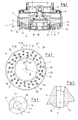
- a shower head intended for the shower area, the but can also be used in other areas can be provided with the reference symbol 1 in FIG. 1.
- This shower head 1 has a disc-shaped housing 2, in that opens up the water connection 3.
- a bottom plate 4 clamped on their special features further back is received.
- the base plate 4 has a large number of water jet nozzles 5, 6, 7, which in principle all the have the same shape, but with the exit angle depending on the level in which the outlet opening 10 of the individual Water jet nozzles 5, 6, 7 is arranged differently can be.
- the middle part 8 of the base plate 4 serves at the same time as a holder for the actual base plate 4 as here Washer is formed. This middle part 8 is about Attachment 9 fixed to the housing 2, at the same time thus, as already mentioned, the annular base plate 4 is supported becomes.
- the individual outlet openings 10 of the water jet nozzles 5, 6, 7 have a in the water outlet direction 11 Bulge 12, which is indicated in Fig. 1, but Fig. 4 can be seen particularly clearly.
- This bulge 12 is hemispherical to avoid straight, rugged edges. This makes cleaning limescale deposits essential facilitated.
- the individual water jet nozzles 5, 6, 7 are each in Rows 15 and 16 arranged, the details of the Hole pattern Fig. 2 can be taken and in the context of Explanations to Fig. 2 are also described in more detail.
- the bottom plate 4 is according to FIG. 1 between the edge of the housing 22 and middle part 8 clamped.
- the bottom plate 4 has both edges via a groove 23 of the same design, 24, an O-ring 25 being mounted in each of these grooves, to seal this area and ensure that the all water only via the water jet nozzles 5, 6, 7 den Can leave the area of the shower head.
- FIG. 2 and FIG. 3 The shape of the individual bulge 12 is illustrated in FIG. 2 and FIG. 3, wherein FIG. 3 is an enlarged representation of a the bulges 12. This shows that the bulge has the shape of an ellipse, the by the Circular center 19 going beam 20 both focal points 17, 18 intersects this ellipse.
- the outlet opening 10 is like 3 explains, shifted in the direction of the focal point 17, so that a different distance between the individual bulge areas to the outlet opening 10 or its edge 13 given is.
- Fig. 2 illustrates that the individual bulges 12th or water jet nozzles 5, 6, 7 each in rows of two 27, 28 are summarized, with each of these rows of two 27th and 28 the associated two water jet nozzles 5 'and 6' are staggered.
- Fig. 2 also illustrates that the individual water jet nozzles 5, 6, 7 combined into groups of four 31, 32 that are on one from the inner edge 33 to the outer edge 34 pointing, fleeing bow 35 arranged evenly distributed are. This results in the effect already described, that none of the water jet nozzles 5 are exactly on the same Beam 20, 20 ', 20' 'is, but rather offset on its own beam or, and beyond, again on the described sheet 35.
- the hole pattern of the base plate 4 described provides for an optimized overall jet of the shower head 1 and on the other hand, it makes cleaning easier. This purge the arrangement of the individual bulges also accommodates 12 - with the narrow side facing the cleaning direction - if you assume that cleaning is usually done the cleaning rag or whatever in a circle is moved.
- the special design of the base plate 4 corresponds 1 that the bottom plate 4 in the form of the annular disc and the middle part 8 form a spherical surface 30, so that the individual water jet nozzles 5, 6, 7, as shown in FIG. 1, yes illustrates in different levels of the base plate 4 emerge.
Abstract
Description
Die Erfindung betrifft einen Brausekopf, insbesondere für den Sanitärbereich und dort für die Dusche, mit einem scheibenförmigen Gehäuse, dem einerseits in den Handgriff und andererseits in das Gehäuse übergehenden Wasseranschluß und einer Bodenplatte mit mehreren Reihen von Wasseraustrittsöffnungen.The invention relates to a shower head, in particular for the sanitary area and there for the shower, with a disc-shaped housing, the one hand in the handle and on the other hand, water connection passing into the housing and a base plate with several rows of water outlet openings.
Derartige Brauseköpfe werden im Sanitärbereich sowohl für den Bereich der Dusche wie der Badewanne, aber auch für andere Zwecke eingesetzt. Bekannt sind sie beispielsweise in entsprechend zugeschnittener Form auch für das Wasserbecken im Küchenbereich. Insbesondere der Brausekopf von Duscheinrichtungen neigt insbesondere in Gegenden zu Verstopfungen, wo der Kalkanteil im Wasser hoch ist. Dabei setzt sich im Austrittsbereich Kalk an, der in der Regel nur mechanisch entfernt werden kann, weil der ausfallende Kalk so weit hart wird, daß er auch durch das später wieder mit entsprechender Fließgeschwindigkeit und Druck austretende Wasser nicht mehr mit weggespült wird. Bekannt ist es, stromabwärts der Wasseraustrittsöffnungen bzw. Düsen ein Verschlußglied vorzusehen, das bei Betriebsruhe die Düse verschließt (DE OS 40 39 338, DE OS 40 39 329 oder auch DE OS 40 39 328) oder aber den Querschnitt einer den Düsen nachgeordneten Fluidaustrittsöffnung größer zu bemessen als den Fluideinlaß (EP-A1 0 478 999, EP-A3 0 435 030). Nachteilig dabei ist, daß die Konstruktion des Brausekopfes damit erheblich verkompliziert wird und daß dennoch ein Austrocknen und damit Festsetzen der Kalkablagerungen nicht mit der notwendigen Sicherheit verhindert werden kann. Bekannt ist es auch, dem Bodenteil gummielastische, schlauchartige Wasserstrahldüsen zuzuordnen, um so das Festsetzen von Kalkablagerungen zu verhindern. Dabei besteht das Bodenteil aus einem Kunststoffverbundmaterial, wobei die Wasserstrahldüsen an eine Trägerplatte aus Kunststoff angespritzt sind (DE OS 43 08 599.7). Bei der EP-A-443 538 sind die Wasserstrahldüsen Teil einer sich auf der Bodenplatte abstützenden elastischen Düsenplatte. Die DE OS 40 39 337.2 beschreibt einen selbstreinigenden Brausekopf, bei dem dem aus elastischen Material bestehenden Bodenteil ein elastischer Strahlbildner zugeordnet ist, um bei Beaufschlagung mit Druckwasser eine elastische Verformung am Strahlbildner zu erreichen. Auch diese Lösungen sind sehr aufwendig und erfordern verhältnismäßig hohe Elastizität der einzelnen Bauteile, was bei den auftretenden Wasserdrücken und den Einsatzbedingungen zu Schwierigkeiten führen kann. Nicht vergessen werden darf dabei, daß in diesem Bereich mit höheren Temperaturen gearbeitet wird, so daß sich die Eigenschaften des Materials auch noch wieder ändern.Such shower heads are both in the sanitary area for the area of the shower and the bathtub, but also for other purposes. They are known for example in appropriately tailored shape also for the water basin in the kitchen area. In particular the shower head of shower facilities is prone to constipation, especially in areas where the lime content in the water is high. It sits in Lime outlet area, which is usually only mechanical can be removed because the precipitated lime hard so far is that he also later with the appropriate Water flow and pressure escaping no longer is washed away with. It is known downstream of the water outlet openings or nozzles to provide a closure member, that closes the nozzle when the machine is idle (DE OS 40 39 338, DE OS 40 39 329 or also DE OS 40 39 328) or the Cross section of a fluid outlet opening downstream of the nozzles larger than the fluid inlet (EP-A1 0 478 999, EP-A3 0 435 030). The disadvantage here is that the construction the shower head is considerably complicated and that nevertheless drying out and thus setting the limescale deposits cannot be prevented with the necessary security can. It is also known that the base part is rubber-elastic, assign hose-like water jet nozzles so as to get stuck to prevent limescale deposits. Here is what Bottom part made of a composite plastic material, the water jet nozzles molded onto a plastic carrier plate are (DE OS 43 08 599.7). In EP-A-443 538 the water jet nozzles are part of one on the bottom plate supporting elastic nozzle plate. DE OS 40 39 337.2 describes a self-cleaning shower head in which the an elastic base part made of elastic material Beamformers are assigned to act upon Pressurized water to an elastic deformation on the jet to reach. These solutions are also very complex and require relatively high elasticity of the individual components, what about the occurring water pressures and the operating conditions can lead to difficulties. Don't be forgotten may do so in this area with higher temperatures is worked so that the properties of the material also change again.
Der Erfindung liegt damit die Aufgabe zugrunde, einen leicht zu reinigenden, ein optimiertes Strahlbild aufweisenden Brausekopf zu schaffen.The invention is therefore based on the object easy to clean, with an optimized spray pattern To create shower head.
Die Aufgabe wird erfindungsgemäß dadurch gelöst, daß die Bodenplatte aus einem eine Shore-Härte von rund 90 aufweisenden Kunststoff besteht und den Wasseraustrittsöffnungen mit jeweils in Wasseraustrittsrichtung angeordnete Aufwölbungen aufweist, die in der Draufsicht ellipsenförmig und im Schnitt halbkugelförmig ausgebildet sind. Die aus Kunststoff bestehende Bodenplatte verfügt also im Bereich der Wasseraustrittsöffnungen über entsprechende Aufwölbungen, wo sich wenn der Kalk ablagern kann. Aufgrund der dann vorhandenen Gegebenheiten kann er von diesen Flächen, wo er sich ansetzt, leicht abgewischt werden, ohne die Wirkung der Wasserstrahldüse zu beeinflussen. Selbst wenn über längere Zeit nicht entsprechend gereinigt wird, bleibt das Strahlenbild der Wasserstrahldüsen erhalten, da sich die Ablagerung in einem Teil vollzieht, wo sie den Strahl direkt nicht mehr beeinflussen kann. Die Aufwölbung der Austrittsöffnungen ist ellipsenförmig ausgebildet ist, so daß sich ein Anlagerungsbereich für das zum Festsetzen neigende Kalkmaterial ergibt, der durch die unterschiedliche Entfernung zum Rand der Austrittsöffnungen unterschiedlich mit Kalk belegt ist, wodurch wiederum das Reinigen wesentlich erleichtert wird. Bekannt ist es ja, daß eine "Schwachstellen" aufweisende Schicht von Ablagerungen leichter abgelöst werden kann, als eine gleichmäßige Anlagerungen aufweisende Beschichtung. Schließlich ist es nicht gleichgültig, welcher Kunststoff als Material für die Bodenplatte in Frage kommt. Die Bodenplatte besteht aus einem eine Shore-Härte von rund 90 aufweisenden Kunststoff. Bei einem solchen Kunststoffmaterial ist bei ausreichender Elastizität eine ausreichende Standzeit gewährleistet und vor allem die notwendige Oberfläche gewährleistet, um die Kalkablagerungen leicht und sicher ablösen bzw. letztlich sogar abwischen zu können.The object is achieved in that the Base plate made of a Shore hardness of around 90 There is plastic and the water outlet openings bulges each arranged in the water outlet direction has an ellipse in plan view and in section are hemispherical. The plastic one So bottom plate has in the area of the water outlet openings about corresponding bulges, where if the lime can deposit. Because of the existing conditions can he from these areas where he sits, can be easily wiped off without the effect of the water jet nozzle to influence. Even if not for a long time is cleaned accordingly, the jet pattern of the water jet nozzles remains received because the deposit is in one part takes place where they no longer directly influence the beam can. The arching of the outlet openings is elliptical is formed so that there is an attachment area for gives the lime material that tends to stick, which is caused by the different distance to the edge of the outlet openings differently coated with lime, which in turn cleaning is made much easier. It is known that a "weak point" layer of deposits can be removed more easily than even deposits coating. After all, it is not no matter which plastic as material for the base plate it is a possibility. The base plate consists of one Shore hardness of around 90 plastic. At a such plastic material is with sufficient elasticity ensures a sufficient service life and above all that necessary surface ensures the limescale deposits peel off easily and safely, or even wipe it off can.
Nimmt man sich die Ausbildung der Aufwölbung etwas genauer vor, so ergibt sich, daß es besonders zweckmäßig ist, die ellipsenförmigen Aufwölbungen der Austrittsöffnungen mit ihren Brennpunkten auf einem durch den Kreismittelpunkt der Bodenplatte gehenden Strahl anzuordnen. Wiederum zweckmäßig ist es, wenn dabei die Austrittsöffnung selber zu einem der Brennpunkte nähergerückt ist, so daß der weiter vorne beschriebene Effekt der unterschiedlichen Schichtdicke von Anlagerungen sich gezielt einstellt. Alle Austrittsöffnungen bzw. alle Aufwölbungen verfügen somit über die gleiche Ausbildung und Anordnung, so daß bei einem Bearbeiten, d. h. Säubern bzw. Abwischen nicht einzelne der zu reinigenden Bereiche besonders behandelt werden müssen. Vielmehr sind wenn die Anbackungen bei allen Bohrungen bzw. besser gesagt Wasserstrahldüsen und deren Austrittsöffnungen gleich leicht zu entfernen. Die besondere Form der Aufwölbung wirkt sich positiv aus. Dabei ist es nicht erforderlich, wirklich eine Halbkugel zu bilden, sondern es reicht auch ein Teilbereich davon. Die entsprechend abgerundeten Formen begünstigen das leichte Reinigen. If you take the formation of the bulge a little more closely before, it turns out that it is particularly expedient the elliptical bulges of the outlet openings their focal points on a through the center of the circle Arrange bottom plate going beam. Again useful it is when the outlet opening itself becomes one of the Focal points is approaching, so that the one described earlier Effect of the different layer thickness of deposits adapts itself specifically. All outlets or all bulges thus have the same training and arrangement so that when editing, d. H. Do not clean or wipe individual areas to be cleaned need special treatment. Rather are the caking in all holes or rather water jet nozzles and their outlets just as easily remove. The special shape of the bulge has a positive effect out. It doesn't really need a hemisphere to form, but a sub-area of it is enough. The correspondingly rounded shapes favor this easy cleaning.
Für eine gleichmäßig arbeitende Brause ist es besonders zweckmäßig, wenn die Bodenplatte als Ringscheibe ausgebildet und einerseits im Gehäuserand und andererseits im Mittelteil gelagert ist. Eine derartige Ringscheibe kann die auftretenden Kräfte wesentlich besser aufnehmen, als eine durchgehende Bodenplatte, wobei die von der Ringplatte ausgehenden Strahlen eine gleichmäßige Beaufschlagung der Körperteile durchaus sicherstellt und sogar allgemein als angenehm empfunden wird. Diese Ringscheibe ist einerseits im Gehäuserand und andererseits im Mittelteil gelagert, d. h. sie kann zusammen mit dem Mittelteil montiert und demontiert werden, wobei die notwendige Dichtheit gewährleistet ist, wenn wie erfindungsgemäß nach einer weiteren Ausbildung vorgesehen ist, die Bodenplatte randseitig jeweils eine Nut aufweist, in der ein gegen den Gehäuserand bzw. das Mittelteil abdichtender O-Ring gelagert ist. Die beiden O-Ringe sind dabei so angeordnet, daß sie für die notwendige Dichtigkeit Sorge tragen und andererseits gewährleisten, daß die ringförmige Bodenplatte sicher gelagert wird.It is special for a uniform shower useful if the base plate is designed as an annular disc and on the one hand in the housing edge and on the other hand in the middle part is stored. Such an annular disc can be the one that occurs Absorb forces much better than a continuous one Base plate, the rays emanating from the ring plate an even application to the body parts ensures and is even generally perceived as pleasant. This washer is on the one hand in the housing edge and on the other stored in the middle section, d. H. together with the Middle part can be assembled and disassembled, taking the necessary Tightness is guaranteed if as according to the invention after a further training is provided, the bottom plate has a groove on the edge in which one against the Housing edge or the middle part sealing O-ring stored is. The two O-rings are arranged so that they are for ensure the necessary tightness and on the other hand ensure that the annular base plate is securely mounted becomes.
Das Lochbild der Bodenplatte ist gemäß der vorliegenden Erfindung dadurch gekennzeichnet, daß die Wasseraustrittsdüsen auf der Bodenplatte auf durch den Kreismittelpunkt der Bodenplatte gehenden Strahlen, in Zweierreihen versetzt zueinander ausgebildet sind. Durch den leichten Versatz der einzelnen Wasseraustrittsdüsen bzw. deren Aufwölbung werden beim Wischen die einzelnen Aufwölbungen nacheinander beaufschlagt, so daß der Reinigungseffekt damit verbessert ist. Außerdem ergibt sich so ein sehr zweckmäßiges Lochbild, wobei eine ergänzende Darstellung die Anordung auch so interpretiert, daß die Wasseraustrittsdüsen in Vierergruppen in einem vom Innenrand zum Außenrand fliehend verlaufenden Bogen angeordnet sind. Näheres hierzu wird im Rahmen der Figuren noch gezeigt und erläutert, wobei diese besondere Anordnung in Vierergruppen den bereits erwähnten Effekt steigert, nämlich daß beim Reinigen praktisch nie mehrere Aufwölbungen gleichzeitig beeinflußt werden, sondern immer eine nach der anderen. Außerdem ist so ein optimales Strahlenbild gegeben, d. h. es ergibt sich ein gleichförmig beschickter Wassermantel, der auf den Körper des Duschenden oder sich Reinigenden einwirkt.The hole pattern of the base plate is according to the present Invention characterized in that the water outlet nozzles on the base plate through the center of the circle Base plate rays, offset in two rows to each other are trained. Due to the slight offset of the individual water outlet nozzles or their bulging the individual bulges are applied one after the other when wiping, so that the cleaning effect is improved. This also results in a very useful hole pattern, whereby a supplementary illustration also interprets the arrangement that the water outlet nozzles in groups of four in an arc running from the inner edge to the outer edge are arranged. More on this is in the context of the figures still shown and explained, this particular arrangement in groups of four increases the already mentioned effect, namely that practically never several bulges when cleaning be influenced at the same time, but always one after the other. In addition, there is an optimal radiation pattern, d. H. the result is a uniformly charged water jacket, on the body of the showering or cleaning acts.
Wiederum zum Erzielen eines optimalen Wasserstrahlbildes und zur Optimierung der Bestrahlung des zu Reinigenden ist vorgesehen, daß die Wasseraustrittsdüsen je nach Entfernung vom Gehäuserand unterschiedliche Austrittswinkel aufweisen, wobei die Grundfließrichtung bzw. Strahlrichtung natürlich vorgegeben ist und etwa rechtwinklig zur Mittelachse des Brausekopfes verläuft.Again to achieve an optimal water jet image and to optimize the radiation to be cleaned provided that the water outlet nozzles depending on the distance have different exit angles from the edge of the housing, the basic flow direction or jet direction of course is specified and approximately at right angles to the central axis of the Shower head runs.
Einer weiteren Optimierung der Reinigungsmöglichkeit dient eine Ausbildung, nach der die Bodenplatte mit dem Mittelteil eine nach außen gewölbte Kugelfläche bildend geformt ist, was bewirkt, daß die einzelnen Austrittsöffnungen der Wasserstrahldüsen in unterschiedlichen Ebenen liegen und damit einmal günstiger zu reinigen sind und zum anderen ein optimiertes Lochbild bzw. Strahlbild ergeben. Die gleichförmigen Wasserstrahlen wirken dabei aufgrund des Austrittswinkels und der Austrittsebene so, daß auch nach langer Standzeit der beschriebene Effekt gewahrt bleibt. Im übrigen gibt es natürlich immer die Möglichkeit, die Ringscheibe bei extremer Verschmutzung oder gar bei Beschädigungen auszuwechseln, um auf diese Art und Weise eine sofort wieder optimal funktionsfähige Brause zu erhalten.A further optimization of the cleaning possibility serves a training, according to which the base plate with the middle part forming an outwardly curved spherical surface is what causes the individual outlet openings of the Water jet nozzles are in different levels and thus are cheaper to clean once and the other one result in an optimized hole pattern or jet pattern. The uniform Water jets act due to the exit angle and the exit level so that even after a long time Service life the effect described is maintained. Furthermore there is of course always the option of adding the washer extreme pollution or even in the event of damage, to be optimal again in this way to get a functional shower.
Die Ringscheibe verfügt über die notwendige Standzeit, da die aus TPE-Kunststoff bestehende eigentliche Fläche der Ringscheibe und die vorstehenden Aufwölbungen nicht durch die Abreinigung beschädigt werden können.The ring disc has the necessary service life, because the actual area of the TPE plastic Washer and the protruding bulges not by the Cleaning can be damaged.
Die Erfindung zeichnet sich insbesondere dadurch aus, daß ein Brausekopf geschaffen ist, der im Aufbau verhältnismäßig einfach gehalten ist, dennoch aber leicht bezüglich der Kalkablagerungen zu reinigen ist. Darüber hinaus verfügt er über ein optimiertes Lochbild, das nicht nur das Reinigen erleichtert, sondern gleichzeitig auch die Strahlbildung zu einem vorteilhaft gleichförmigen Gesamtstrahl vorgibt. Der Brausekopf verfügt darüber hinaus über günstige Standzeiten und ermöglicht bei Bedarf auch einen Austausch der die Wasserstrahldüsen aufweisenden Bodenplatte, wenn dies während des Gesamtbetriebes mal notwendig werden sollte. Es ist dagegen nicht erforderlich, den gesamten Brausekopf auszuwechseln.The invention is characterized in particular by that a shower head is created, which is proportional in construction is simple, but still easy in terms of Limescale is to be cleaned. He also has via an optimized hole pattern that is not just cleaning relieved, but at the same time the beam formation too specifies an advantageously uniform overall jet. The In addition, the shower head has a favorable service life and also enables an exchange of the Bottom plate with water jet nozzles, if this during of the entire operation should become necessary. It is against no need to replace the entire shower head.
Weitere Einzelheiten und Vorteile des Erfindungsgegenstandes ergeben sich aus der nachfolgenden Beschreibung der zugehörigen Zeichnung, in der ein bevorzugtes Ausführungsbeispiel mit den dazu notwendigen Einzelheiten und Einzelteilen dargestellt ist. Es zeigen:
- Fig. 1
- einen Querschnitt durch einen Brausekopf mit Bodenplatte,
- Fig. 2
- eine Draufsicht auf die Bodenplatte mit Mittelteil,
- Fig. 3
- eine Draufsicht auf eine Austrittsöffnung einer Wasserstrahldüse und
- Fig. 4
- einen Schnitt durch die Bodenplatte im unteren Bereich einer Austrittsöffnung.
- Fig. 1
- a cross section through a shower head with base plate,
- Fig. 2
- a plan view of the base plate with middle part,
- Fig. 3
- a plan view of an outlet opening of a water jet nozzle and
- Fig. 4
- a section through the bottom plate in the lower region of an outlet opening.
Ein für den Duschbereich vorgesehener Brausekopf, der
genausogut aber auch in anderen Bereichen eingesetzt werden
kann, ist in Fig. 1 mit dem Bezugszeichen 1 versehen. Dieser
Brausekopf 1 verfügt über ein scheibenförmiges Gehäuse 2, in
das oben der Wasseranschluß 3 einmündet. Im gegenüberliegenden
flachen Bodenbereich des Gehäuses 2 ist eine Bodenplatte
4 eingespannt, auf deren besondere Merkmale weiter hinten
eingegangen wird.A shower head intended for the shower area, the
but can also be used in other areas
can be provided with the
Die Bodenplatte 4 ist mit einer Vielzahl von Wasserstrahldüsen
5, 6, 7 bestückt, die vom Grundsatz her alle die
gleiche Form aufweisen, wobei allerdings der Austrittswinkel
je nach Ebene, in der die Austrittsöffnung 10 der einzelnen
Wasserstrahldüsen 5, 6, 7 angeordnet ist, unterschiedlich
sein kann.The base plate 4 has a large number of
Das Mittelteil 8 der Bodenplatte 4 dient gleichzeitig
als Halterung für die eigentliche Bodenplatte 4 die hier als
Ringscheibe ausgebildet ist. Dieses Mittelteil 8 ist über die
Befestigung 9 an dem Gehäuse 2 festgelegt, wobei gleichzeitig
damit, wie schon erwähnt, die ringförmige Bodenplatte 4 abgestützt
wird.The
Die einzelnen Austrittsöffnungen 10 der Wasserstrahldüsen
5, 6, 7 verfügen in Wasseraustrittsrichtung 11 über eine
Aufwölbung 12, was in Fig. 1 angedeutet ist, der Fig. 4 aber
besonders deutlich entnommen werden kann. Diese Aufwölbung 12
ist halbkugelförmig, um so gerade, schroffe Kanten zu vermeiden.
Dadurch wird das Abreinigen von Kalkablagerungen wesentlich
erleichtert.The
Die einzelnen Wasserstrahldüsen 5, 6, 7 sind jeweils in
Reihen 15 bzw. 16 angeordnet, wobei die Einzelheiten des
Lochbildes Fig. 2 entnommen werden können und im Rahmen der
Erläuterungen zu Fig. 2 auch noch näher beschrieben werden.The individual
Die Bodenplatte 4 ist gemäß Fig. 1 zwischen Gehäuserand
22 und Mittelteil 8 eingespannt. Die Bodenplatte 4 verfügt an
beiden Rändern über jeweils eine gleich ausgebildete Nut 23,
24, wobei in jeder dieser Nuten ein O-Ring 25 gelagert ist,
um diesen Bereich abzudichten und sicherzustellen, daß das
gesamte Wasser nur über die Wasserstrahldüsen 5, 6, 7 den
Bereich des Brausekopfes verlassen kann.The bottom plate 4 is according to FIG. 1 between the edge of the
Die Form der einzelnen Aufwölbung 12 verdeutlicht Fig. 2
und Fig. 3, wobei Fig. 3 eine vergrößerte Wiedergabe einer
der Aufwölbungen 12 ist. Hier zeigt sich, daß die Aufwölbung
die Form einer Ellipse aufweist, wobei der durch den
Kreismittelpunkt 19 gehende Strahl 20 beide Brennpunkte 17,
18 dieser Ellipse schneidet. Die Austrittsöffnung 10 ist wie
Fig. 3 erläutert, in Richtung auf den Brennpunkt 17 verschoben,
so daß ein unterschiedlicher Abstand der einzelnen Aufwölbungsbereiche
zur Austrittsöffnung 10 bzw. dessen Kante 13
gegeben ist.The shape of the
Fig. 2 verdeutlicht, daß die einzelnen Aufwölbungen 12
bzw. Wasserstrahldüsen 5, 6, 7 jeweils zu Zweierreihen 27, 28
zusammengefaßt sind, wobei bei jeder dieser Zweierreihen 27
und 28 die dazugehörigen beiden Wasserstrahldüsen 5' und 6'
versetzt zueinander angeordnet sind.Fig. 2 illustrates that the individual bulges 12th
or
Fig. 2 verdeutlicht aber auch, daß die einzelnen Wasserstrahldüsen
5, 6, 7 zu Vierergruppen 31, 32 zusammengefaßt
sind, die auf einem von dem Innenrand 33 zum Außenrand 34
weisenden, fliehenden Bogen 35 gleichmäßig verteilt angeordnet
sind. Dadurch ergibt sich der schon beschriebene Effekt,
daß keine der Wasserstrahldüsen 5 genau auf dem gleichen
Strahl 20, 20', 20'' liegt, sondern vielmehr jeweils versetzt
auf einem eigenen Strahl bzw. und darüber hinaus noch wieder
auf dem beschriebenen Bogen 35.Fig. 2 also illustrates that the individual
Das beschriebene Lochbild der Bodenplatte 4 erbringt zum
einen einen optimierten Gesamtstrahl des Brausekopfes 1 und
zum anderen eine Erleichterung beim Säubern. Dieser Säuberung
entgegen kommt auch die Anordnung der einzelnen Aufwölbungen
12 - quasi mit der Schmalseite zur Reinigungsrichtung gerichtet
- , wenn man mal davon ausgeht, daß beim Reinigen üblicherweise
der Reinigungslappen oder was auch immer im Kreise
bewegt wird.The hole pattern of the base plate 4 described provides for
an optimized overall jet of the
Der besonderen Ausbildung der Bodenplatte 4 entspricht
es gemäß Fig. 1, daß die Bodenplatte 4 in Form der Ringscheibe
und das Mittelteil 8 eine Kugelfläche 30 bilden, so daß
die einzelnen Wasserstrahldüsen 5, 6, 7, wie Fig. 1 ja schon
verdeutlicht, in unterschiedlichen Ebenen der Bodenplatte 4
austreten. The special design of the base plate 4 corresponds
1 that the bottom plate 4 in the form of the annular disc
and the
Alle genannten Merkmale, auch die den Zeichnungen allein zu entnehmenden, werden allein und in Kombination als erfindungswesentlich angesehen.All mentioned features, including those of the drawings alone to be removed, alone and in combination, are essential to the invention viewed.
Claims (9)
- Shower head, in particular for the field of sanitation and therein for the shower, with a disc-shaped housing (2), the water connection (3) passing on one side into the handle and on the other side into the housing (2) and a base plate (4) with several rows (15, 16) of water outlet openings (10), characterised in that the base plate (4) consists of a synthetic material having a Shore hardness of approximately 90 and comprises the water outlet openings (10) with water-jet nozzles (5, 6, 7) and bulges (12) located respectively in the water outlet direction (11), which are constructed to be elliptical in plan view and hemispherical in section.
- Shower head according to Claim 1, characterised in that the elliptical bulges (12) of the outlet openings (10) are arranged with their foci (17, 18) on a radius (20) passing through the centre point (19) of the base plate (4).
- Shower head according to Claim 1, characterised in that the base plate (4) is constructed as an annular disc and is mounted on one side in the edge of the housing (22) and on the other side in the central part (8).
- Shower head according to Claim 3, characterised in that on its edges the base plate (4) comprises respectively one groove (23, 24), in which is mounted an O-ring (25) sealing against the edge of the housing (22) or the central part (8).
- Shower head according to Claim 1, characterised in that the water-outlet nozzles (5, 6, 7) are arranged to be staggered with respect to each other in rows of two (27, 28) on the base plate (4) on radii (20) passing through the centre point (19) of the base plate.
- Shower head according to Claim 1, characterised in that the water outlet nozzles (5, 6, 7) have different outlet angles depending on their distance from the edge of the housing (22).
- Shower head according to Claim 1, characterised in that the base plate (4) with the central part (8) is shaped to form an outwardly curved spherical surface (30).
- Shower head according to Claim 1, characterised in that the water outlet nozzles (5, 6, 7) are arranged in groups of four (31, 32) in a curve (35) extending in a sloping manner from the inner edge (33) to the outer edge (34).
- Shower head according to Claim 1, characterised in that the base plate (4) consists of a PET synthetic material.
Applications Claiming Priority (2)
| Application Number | Priority Date | Filing Date | Title |
|---|---|---|---|
| DE4432327A DE4432327C2 (en) | 1994-09-10 | 1994-09-10 | Easy to clean shower head |
| DE4432327 | 1994-09-10 |
Publications (2)
| Publication Number | Publication Date |
|---|---|
| EP0700729A1 EP0700729A1 (en) | 1996-03-13 |
| EP0700729B1 true EP0700729B1 (en) | 2000-02-09 |
Family
ID=6527944
Family Applications (1)
| Application Number | Title | Priority Date | Filing Date |
|---|---|---|---|
| EP95112664A Revoked EP0700729B1 (en) | 1994-09-10 | 1995-08-11 | Easily cleanable shower head |
Country Status (8)
| Country | Link |
|---|---|
| EP (1) | EP0700729B1 (en) |
| AT (1) | ATE189623T1 (en) |
| CZ (1) | CZ204295A3 (en) |
| DE (2) | DE4432327C2 (en) |
| DK (1) | DK0700729T3 (en) |
| ES (1) | ES2144549T3 (en) |
| HU (1) | HU215677B (en) |
| PL (1) | PL177778B1 (en) |
Cited By (22)
| Publication number | Priority date | Publication date | Assignee | Title |
|---|---|---|---|---|
| USD641831S1 (en) | 2009-10-05 | 2011-07-19 | Water Pik, Inc. | Showerhead |
| US8020788B2 (en) | 2002-12-10 | 2011-09-20 | Water Pik, Inc. | Showerhead with enhanced pause mode |
| US8020787B2 (en) | 2006-11-29 | 2011-09-20 | Water Pik, Inc. | Showerhead system |
| US8028935B2 (en) | 2007-05-04 | 2011-10-04 | Water Pik, Inc. | Low flow showerhead and method of making same |
| US8109450B2 (en) | 2006-11-29 | 2012-02-07 | Water Pik, Inc. | Connection structure for handheld showerhead |
| US8292200B2 (en) | 2004-09-01 | 2012-10-23 | Water Pik, Inc. | Drenching showerhead |
| USD673649S1 (en) | 2012-01-27 | 2013-01-01 | Water Pik, Inc. | Ring-shaped wall mount showerhead |
| US8348181B2 (en) | 2008-09-15 | 2013-01-08 | Water Pik, Inc. | Shower assembly with radial mode changer |
| USD674050S1 (en) | 2012-01-27 | 2013-01-08 | Water Pik, Inc. | Ring-shaped handheld showerhead |
| US8366024B2 (en) | 2006-12-28 | 2013-02-05 | Water Pik, Inc. | Low speed pulsating showerhead |
| US8616470B2 (en) | 2010-08-25 | 2013-12-31 | Water Pik, Inc. | Mode control valve in showerhead connector |
| US8733675B2 (en) | 2006-04-20 | 2014-05-27 | Water Pik, Inc. | Converging spray showerhead |
| US8794543B2 (en) | 2006-12-28 | 2014-08-05 | Water Pik, Inc. | Low-speed pulsating showerhead |
| USD744066S1 (en) | 2014-06-13 | 2015-11-24 | Water Pik, Inc. | Wall mount showerhead |
| USD744064S1 (en) | 2014-06-13 | 2015-11-24 | Water Pik, Inc. | Handheld showerhead |
| USD744065S1 (en) | 2014-06-13 | 2015-11-24 | Water Pik, Inc. | Handheld showerhead |
| USD744614S1 (en) | 2014-06-13 | 2015-12-01 | Water Pik, Inc. | Wall mount showerhead |
| USD744611S1 (en) | 2014-06-13 | 2015-12-01 | Water Pik, Inc. | Handheld showerhead |
| USD744612S1 (en) | 2014-06-13 | 2015-12-01 | Water Pik, Inc. | Handheld showerhead |
| USD745111S1 (en) | 2014-06-13 | 2015-12-08 | Water Pik, Inc. | Wall mount showerhead |
| US9404243B2 (en) | 2013-06-13 | 2016-08-02 | Water Pik, Inc. | Showerhead with turbine driven shutter |
| USD803981S1 (en) | 2016-02-01 | 2017-11-28 | Water Pik, Inc. | Handheld spray nozzle |
Families Citing this family (9)
| Publication number | Priority date | Publication date | Assignee | Title |
|---|---|---|---|---|
| DE102005012706B4 (en) * | 2005-03-11 | 2006-11-23 | Hansa Metallwerke Ag | showerhead |
| CA2898716C (en) | 2012-06-22 | 2020-02-11 | Water Pik, Inc. | Bracket for showerhead with integral flow control |
| CN103769322B (en) * | 2014-01-09 | 2016-08-31 | 张爱恨 | A kind of air hybrid top spraying gondola with self-cleaning function |
| CA3013213C (en) | 2016-02-01 | 2021-04-20 | Water Pik, Inc. | Handheld pet spray wand |
| USD970684S1 (en) | 2016-04-15 | 2022-11-22 | Water Pik, Inc. | Showerhead |
| US10265710B2 (en) | 2016-04-15 | 2019-04-23 | Water Pik, Inc. | Showerhead with dual oscillating massage |
| CN113856927B (en) | 2016-09-08 | 2023-02-21 | 洁碧有限公司 | Pause assembly for showerhead |
| USD843549S1 (en) | 2017-07-19 | 2019-03-19 | Water Pik, Inc. | Handheld spray nozzle |
| USD872227S1 (en) | 2018-04-20 | 2020-01-07 | Water Pik, Inc. | Handheld spray device |
Family Cites Families (9)
| Publication number | Priority date | Publication date | Assignee | Title |
|---|---|---|---|---|
| US3893628A (en) * | 1974-04-08 | 1975-07-08 | Alsons Corp | Spray head |
| DE4039328A1 (en) * | 1989-12-28 | 1991-07-04 | Grohe Armaturen Friedrich | Shower outlet head - has double outlet plate and valve which enables water to collect between plates after water supply is shut off |
| DE3943058A1 (en) * | 1989-12-28 | 1991-07-04 | Grohe Armaturen Friedrich | SHOWER HEAD |
| DE4039338A1 (en) * | 1989-12-28 | 1991-07-04 | Grohe Armaturen Friedrich | Shower bath head - has rotary disc to prevent build-up of lime deposit around outlet holes |
| DE4039329C2 (en) * | 1989-12-28 | 2000-02-24 | Grohe Armaturen Friedrich | Shower head |
| DE4039337A1 (en) * | 1989-12-28 | 1991-07-04 | Grohe Armaturen Friedrich | Shower bath outlet head - has flexible disc in outlet which is deformed by water pressure and prevents build-up of lime deposits |
| US5228625A (en) * | 1990-02-22 | 1993-07-20 | Masco Gmbh | Sprinkler head |
| DE4031206A1 (en) * | 1990-10-04 | 1992-04-09 | Grohe Armaturen Friedrich | SHOWER HEAD |
| DE9303986U1 (en) * | 1992-11-04 | 1993-08-12 | Friedrich Grohe Ag, 58675 Hemer, De |
-
1994
- 1994-09-10 DE DE4432327A patent/DE4432327C2/en not_active Expired - Fee Related
-
1995
- 1995-07-06 HU HU9502060A patent/HU215677B/en not_active IP Right Cessation
- 1995-08-09 CZ CZ952042A patent/CZ204295A3/en unknown
- 1995-08-11 EP EP95112664A patent/EP0700729B1/en not_active Revoked
- 1995-08-11 DE DE59507772T patent/DE59507772D1/en not_active Expired - Fee Related
- 1995-08-11 DK DK95112664T patent/DK0700729T3/en active
- 1995-08-11 AT AT95112664T patent/ATE189623T1/en not_active IP Right Cessation
- 1995-08-11 ES ES95112664T patent/ES2144549T3/en not_active Expired - Lifetime
- 1995-09-07 PL PL95310309A patent/PL177778B1/en unknown
Cited By (32)
| Publication number | Priority date | Publication date | Assignee | Title |
|---|---|---|---|---|
| US8020788B2 (en) | 2002-12-10 | 2011-09-20 | Water Pik, Inc. | Showerhead with enhanced pause mode |
| US8905332B2 (en) | 2002-12-10 | 2014-12-09 | Water Pik, Inc. | Dual turbine showerhead |
| US8292200B2 (en) | 2004-09-01 | 2012-10-23 | Water Pik, Inc. | Drenching showerhead |
| US8733675B2 (en) | 2006-04-20 | 2014-05-27 | Water Pik, Inc. | Converging spray showerhead |
| US8020787B2 (en) | 2006-11-29 | 2011-09-20 | Water Pik, Inc. | Showerhead system |
| US8109450B2 (en) | 2006-11-29 | 2012-02-07 | Water Pik, Inc. | Connection structure for handheld showerhead |
| US8132745B2 (en) | 2006-11-29 | 2012-03-13 | Water Pik, Inc. | Showerhead with tube connectors |
| US8794543B2 (en) | 2006-12-28 | 2014-08-05 | Water Pik, Inc. | Low-speed pulsating showerhead |
| US8366024B2 (en) | 2006-12-28 | 2013-02-05 | Water Pik, Inc. | Low speed pulsating showerhead |
| US8146838B2 (en) | 2006-12-29 | 2012-04-03 | Water Pik, Inc. | Handheld showerhead with mode control in handle |
| US8584972B2 (en) | 2006-12-29 | 2013-11-19 | Water Pik, Inc. | Handheld showerhead with fluid passageways |
| US8967497B2 (en) | 2006-12-29 | 2015-03-03 | Water Pik, Inc. | Handheld showerhead with mode selector in handle |
| US8371618B2 (en) | 2007-05-04 | 2013-02-12 | Water Pik, Inc. | Hidden pivot attachment for showers and method of making same |
| US9127794B2 (en) | 2007-05-04 | 2015-09-08 | Water Pik, Inc. | Pivot attachment for showerheads |
| US8028935B2 (en) | 2007-05-04 | 2011-10-04 | Water Pik, Inc. | Low flow showerhead and method of making same |
| US8348181B2 (en) | 2008-09-15 | 2013-01-08 | Water Pik, Inc. | Shower assembly with radial mode changer |
| US8757517B2 (en) | 2008-09-15 | 2014-06-24 | Water Pik, Inc. | Showerhead with flow directing plates and radial mode changer |
| USD641831S1 (en) | 2009-10-05 | 2011-07-19 | Water Pik, Inc. | Showerhead |
| US8616470B2 (en) | 2010-08-25 | 2013-12-31 | Water Pik, Inc. | Mode control valve in showerhead connector |
| USD673649S1 (en) | 2012-01-27 | 2013-01-01 | Water Pik, Inc. | Ring-shaped wall mount showerhead |
| USD678463S1 (en) | 2012-01-27 | 2013-03-19 | Water Pik, Inc. | Ring-shaped wall mount showerhead |
| USD678467S1 (en) | 2012-01-27 | 2013-03-19 | Water Pik, Inc. | Ring-shaped handheld showerhead |
| USD674050S1 (en) | 2012-01-27 | 2013-01-08 | Water Pik, Inc. | Ring-shaped handheld showerhead |
| US9404243B2 (en) | 2013-06-13 | 2016-08-02 | Water Pik, Inc. | Showerhead with turbine driven shutter |
| USD744066S1 (en) | 2014-06-13 | 2015-11-24 | Water Pik, Inc. | Wall mount showerhead |
| USD744064S1 (en) | 2014-06-13 | 2015-11-24 | Water Pik, Inc. | Handheld showerhead |
| USD744065S1 (en) | 2014-06-13 | 2015-11-24 | Water Pik, Inc. | Handheld showerhead |
| USD744614S1 (en) | 2014-06-13 | 2015-12-01 | Water Pik, Inc. | Wall mount showerhead |
| USD744611S1 (en) | 2014-06-13 | 2015-12-01 | Water Pik, Inc. | Handheld showerhead |
| USD744612S1 (en) | 2014-06-13 | 2015-12-01 | Water Pik, Inc. | Handheld showerhead |
| USD745111S1 (en) | 2014-06-13 | 2015-12-08 | Water Pik, Inc. | Wall mount showerhead |
| USD803981S1 (en) | 2016-02-01 | 2017-11-28 | Water Pik, Inc. | Handheld spray nozzle |
Also Published As
| Publication number | Publication date |
|---|---|
| ES2144549T3 (en) | 2000-06-16 |
| CZ204295A3 (en) | 1996-03-13 |
| PL177778B1 (en) | 2000-01-31 |
| EP0700729A1 (en) | 1996-03-13 |
| HU215677B (en) | 1999-02-01 |
| DK0700729T3 (en) | 2000-07-24 |
| HUT72377A (en) | 1996-04-29 |
| ATE189623T1 (en) | 2000-02-15 |
| DE59507772D1 (en) | 2000-03-16 |
| DE4432327A1 (en) | 1996-03-14 |
| HU9502060D0 (en) | 1995-09-28 |
| PL310309A1 (en) | 1996-03-18 |
| DE4432327C2 (en) | 1998-07-02 |
Similar Documents
| Publication | Publication Date | Title |
|---|---|---|
| EP0700729B1 (en) | Easily cleanable shower head | |
| DE4105183C5 (en) | shower head | |
| EP0435031B1 (en) | Shower head | |
| DE3729692C2 (en) | Cleaning device for swimming pools | |
| EP0435030A2 (en) | Shower head | |
| EP1001095B1 (en) | Water aerator | |
| EP3338898B1 (en) | Spray jet outlet device and spray equipped with same | |
| EP2192852A1 (en) | Dishwasher | |
| DE3419698A1 (en) | DEVICE FOR MECHANICAL CLEANING OF LIQUIDS | |
| DE2056552A1 (en) | Outlet body for optional He generation of a flow pattern, in particular special for pipe connections to water basins | |
| DE3505438A1 (en) | SHOWER HEAD | |
| DE2149097C3 (en) | Device for automatic cleaning of toilet seats | |
| EP1259331B1 (en) | Shower head | |
| DE4039337A1 (en) | Shower bath outlet head - has flexible disc in outlet which is deformed by water pressure and prevents build-up of lime deposits | |
| EP1619315A1 (en) | Jet regulator | |
| DE3203090A1 (en) | Electrode cleaning device for water chlorinating and sterilising units | |
| EP0372538B1 (en) | Windscreen wiper blade | |
| DE6921769U (en) | OUTLET MOUTH PIECE FOR LOW-SPRAYING FLOWS | |
| EP2674085B1 (en) | Toilet brush | |
| DE2901013A1 (en) | Hand held spray head for shower bath - has resilient spray disc clamped inside, forced into curved shape by water pressure | |
| DE2111829C3 (en) | Self-cleaning spray head | |
| DE112019004251T5 (en) | Water outlet nozzle and water jet device with the same | |
| DE69815804T2 (en) | shower head | |
| DE2108103C3 (en) | Washing devices, in particular for sanitary purposes | |
| EP1247911A2 (en) | Cleaning device |
Legal Events
| Date | Code | Title | Description |
|---|---|---|---|
| PUAI | Public reference made under article 153(3) epc to a published international application that has entered the european phase |
Free format text: ORIGINAL CODE: 0009012 |
|
| AK | Designated contracting states |
Kind code of ref document: A1 Designated state(s): AT BE CH DE DK ES FR GB GR IE IT LI LU MC NL PT SE |
|
| 17P | Request for examination filed |
Effective date: 19960622 |
|
| 17Q | First examination report despatched |
Effective date: 19981015 |
|
| GRAG | Despatch of communication of intention to grant |
Free format text: ORIGINAL CODE: EPIDOS AGRA |
|
| GRAG | Despatch of communication of intention to grant |
Free format text: ORIGINAL CODE: EPIDOS AGRA |
|
| GRAH | Despatch of communication of intention to grant a patent |
Free format text: ORIGINAL CODE: EPIDOS IGRA |
|
| GRAH | Despatch of communication of intention to grant a patent |
Free format text: ORIGINAL CODE: EPIDOS IGRA |
|
| GRAA | (expected) grant |
Free format text: ORIGINAL CODE: 0009210 |
|
| AK | Designated contracting states |
Kind code of ref document: B1 Designated state(s): AT BE CH DE DK ES FR GB GR IE IT LI LU MC NL PT SE |
|
| PG25 | Lapsed in a contracting state [announced via postgrant information from national office to epo] |
Ref country code: GR Free format text: LAPSE BECAUSE OF NON-PAYMENT OF DUE FEES Effective date: 20000209 |
|
| REF | Corresponds to: |
Ref document number: 189623 Country of ref document: AT Date of ref document: 20000215 Kind code of ref document: T |
|
| REG | Reference to a national code |
Ref country code: CH Ref legal event code: EP |
|
| GBT | Gb: translation of ep patent filed (gb section 77(6)(a)/1977) |
Effective date: 20000209 |
|
| REF | Corresponds to: |
Ref document number: 59507772 Country of ref document: DE Date of ref document: 20000316 |
|
| GBT | Gb: translation of ep patent filed (gb section 77(6)(a)/1977) |
Free format text: ERRATUM: THE FOLLOWING EUROPEAN PATENTS WERE ADVERTISED IN ERROR IN JOURNAL 5781 DATED 1 MARCH 2000 AS HAVING BEEN FILED UNDER SECTION 77(6)(A) ON 8 FEBRUARY 2000. |
|
| REG | Reference to a national code |
Ref country code: IE Ref legal event code: FG4D Free format text: GERMAN |
|
| ITF | It: translation for a ep patent filed |
Owner name: SOCIETA' ITALIANA BREVETTI S.P.A. |
|
| PG25 | Lapsed in a contracting state [announced via postgrant information from national office to epo] |
Ref country code: SE Free format text: LAPSE BECAUSE OF FAILURE TO SUBMIT A TRANSLATION OF THE DESCRIPTION OR TO PAY THE FEE WITHIN THE PRESCRIBED TIME-LIMIT Effective date: 20000509 Ref country code: PT Free format text: LAPSE BECAUSE OF FAILURE TO SUBMIT A TRANSLATION OF THE DESCRIPTION OR TO PAY THE FEE WITHIN THE PRESCRIBED TIME-LIMIT Effective date: 20000509 |
|
| ET | Fr: translation filed | ||
| REG | Reference to a national code |
Ref country code: ES Ref legal event code: FG2A Ref document number: 2144549 Country of ref document: ES Kind code of ref document: T3 |
|
| REG | Reference to a national code |
Ref country code: DK Ref legal event code: T3 |
|
| PG25 | Lapsed in a contracting state [announced via postgrant information from national office to epo] |
Ref country code: LU Free format text: LAPSE BECAUSE OF NON-PAYMENT OF DUE FEES Effective date: 20000811 Ref country code: GB Free format text: LAPSE BECAUSE OF NON-PAYMENT OF DUE FEES Effective date: 20000811 |
|
| PG25 | Lapsed in a contracting state [announced via postgrant information from national office to epo] |
Ref country code: MC Free format text: THE PATENT HAS BEEN ANNULLED BY A DECISION OF A NATIONAL AUTHORITY Effective date: 20000831 Ref country code: BE Free format text: LAPSE BECAUSE OF NON-PAYMENT OF DUE FEES Effective date: 20000831 |
|
| PLBI | Opposition filed |
Free format text: ORIGINAL CODE: 0009260 |
|
| PLBF | Reply of patent proprietor to notice(s) of opposition |
Free format text: ORIGINAL CODE: EPIDOS OBSO |
|
| 26 | Opposition filed |
Opponent name: FRIEDRICH GROHE AG & CO. KG Effective date: 20001102 |
|
| BERE | Be: lapsed |
Owner name: FRANZ SCHEFFER OHG Effective date: 20000831 |
|
| NLR1 | Nl: opposition has been filed with the epo |
Opponent name: FRIEDRICH GROHE AG & CO. KG |
|
| GBPC | Gb: european patent ceased through non-payment of renewal fee |
Effective date: 20000811 |
|
| REG | Reference to a national code |
Ref country code: CH Ref legal event code: PL |
|
| PLBF | Reply of patent proprietor to notice(s) of opposition |
Free format text: ORIGINAL CODE: EPIDOS OBSO |
|
| REG | Reference to a national code |
Ref country code: CH Ref legal event code: NV Representative=s name: SCHMAUDER & PARTNER AG PATENTANWALTSBUERO * SCHMAU Ref country code: CH Ref legal event code: AEN Free format text: DAS PATENT IST AUFGRUND DES WEITERBEHANDLUNGSANTRAGS VOM 14.05.2001 * DAS PATENT IST AUFGRUND DES WEITERBEHANDLUNGSANTRAGS VOM 14.05.2001 |
|
| PLBF | Reply of patent proprietor to notice(s) of opposition |
Free format text: ORIGINAL CODE: EPIDOS OBSO |
|
| PGFP | Annual fee paid to national office [announced via postgrant information from national office to epo] |
Ref country code: FR Payment date: 20010710 Year of fee payment: 7 |
|
| PGFP | Annual fee paid to national office [announced via postgrant information from national office to epo] |
Ref country code: AT Payment date: 20010711 Year of fee payment: 7 |
|
| PGFP | Annual fee paid to national office [announced via postgrant information from national office to epo] |
Ref country code: ES Payment date: 20010821 Year of fee payment: 7 |
|
| PGFP | Annual fee paid to national office [announced via postgrant information from national office to epo] |
Ref country code: DK Payment date: 20010827 Year of fee payment: 7 |
|
| PGFP | Annual fee paid to national office [announced via postgrant information from national office to epo] |
Ref country code: CH Payment date: 20010829 Year of fee payment: 7 |
|
| PGFP | Annual fee paid to national office [announced via postgrant information from national office to epo] |
Ref country code: NL Payment date: 20010831 Year of fee payment: 7 |
|
| PGFP | Annual fee paid to national office [announced via postgrant information from national office to epo] |
Ref country code: DE Payment date: 20010912 Year of fee payment: 7 |
|
| PG25 | Lapsed in a contracting state [announced via postgrant information from national office to epo] |
Ref country code: AT Free format text: LAPSE BECAUSE OF NON-PAYMENT OF DUE FEES Effective date: 20020811 |
|
| PG25 | Lapsed in a contracting state [announced via postgrant information from national office to epo] |
Ref country code: ES Free format text: LAPSE BECAUSE OF NON-PAYMENT OF DUE FEES Effective date: 20020812 |
|
| PG25 | Lapsed in a contracting state [announced via postgrant information from national office to epo] |
Ref country code: LI Free format text: LAPSE BECAUSE OF NON-PAYMENT OF DUE FEES Effective date: 20020831 Ref country code: CH Free format text: LAPSE BECAUSE OF NON-PAYMENT OF DUE FEES Effective date: 20020831 |
|
| PG25 | Lapsed in a contracting state [announced via postgrant information from national office to epo] |
Ref country code: DK Free format text: LAPSE BECAUSE OF NON-PAYMENT OF DUE FEES Effective date: 20020930 |
|
| PLBO | Opposition rejected |
Free format text: ORIGINAL CODE: EPIDOS REJO |
|
| APAC | Appeal dossier modified |
Free format text: ORIGINAL CODE: EPIDOS NOAPO |
|
| PG25 | Lapsed in a contracting state [announced via postgrant information from national office to epo] |
Ref country code: NL Free format text: LAPSE BECAUSE OF NON-PAYMENT OF DUE FEES Effective date: 20030301 Ref country code: DE Free format text: LAPSE BECAUSE OF NON-PAYMENT OF DUE FEES Effective date: 20030301 |
|
| REG | Reference to a national code |
Ref country code: DK Ref legal event code: EBP |
|
| REG | Reference to a national code |
Ref country code: CH Ref legal event code: PL |
|
| APAC | Appeal dossier modified |
Free format text: ORIGINAL CODE: EPIDOS NOAPO |
|
| NLV4 | Nl: lapsed or anulled due to non-payment of the annual fee |
Effective date: 20030301 |
|
| REG | Reference to a national code |
Ref country code: FR Ref legal event code: ST |
|
| APBU | Appeal procedure closed |
Free format text: ORIGINAL CODE: EPIDOSNNOA9O |
|
| RDAF | Communication despatched that patent is revoked |
Free format text: ORIGINAL CODE: EPIDOSNREV1 |
|
| RDAG | Patent revoked |
Free format text: ORIGINAL CODE: 0009271 |
|
| STAA | Information on the status of an ep patent application or granted ep patent |
Free format text: STATUS: PATENT REVOKED |
|
| 27W | Patent revoked |
Effective date: 20030724 |
|
| APAA | Appeal reference recorded |
Free format text: ORIGINAL CODE: EPIDOS REFN |
|
| APAH | Appeal reference modified |
Free format text: ORIGINAL CODE: EPIDOSCREFNO |
|
| PG25 | Lapsed in a contracting state [announced via postgrant information from national office to epo] |
Ref country code: FR Free format text: LAPSE BECAUSE OF NON-PAYMENT OF DUE FEES Effective date: 20020831 |