EP0701109A2 - Watermeter - Google Patents
Watermeter Download PDFInfo
- Publication number
- EP0701109A2 EP0701109A2 EP95112728A EP95112728A EP0701109A2 EP 0701109 A2 EP0701109 A2 EP 0701109A2 EP 95112728 A EP95112728 A EP 95112728A EP 95112728 A EP95112728 A EP 95112728A EP 0701109 A2 EP0701109 A2 EP 0701109A2
- Authority
- EP
- European Patent Office
- Prior art keywords
- water meter
- transmission
- meter according
- counting
- display device
- Prior art date
- Legal status (The legal status is an assumption and is not a legal conclusion. Google has not performed a legal analysis and makes no representation as to the accuracy of the status listed.)
- Withdrawn
Links
Images


Classifications
-
- G—PHYSICS
- G01—MEASURING; TESTING
- G01F—MEASURING VOLUME, VOLUME FLOW, MASS FLOW OR LIQUID LEVEL; METERING BY VOLUME
- G01F1/00—Measuring the volume flow or mass flow of fluid or fluent solid material wherein the fluid passes through a meter in a continuous flow
- G01F1/05—Measuring the volume flow or mass flow of fluid or fluent solid material wherein the fluid passes through a meter in a continuous flow by using mechanical effects
- G01F1/06—Measuring the volume flow or mass flow of fluid or fluent solid material wherein the fluid passes through a meter in a continuous flow by using mechanical effects using rotating vanes with tangential admission
- G01F1/075—Measuring the volume flow or mass flow of fluid or fluent solid material wherein the fluid passes through a meter in a continuous flow by using mechanical effects using rotating vanes with tangential admission with magnetic or electromagnetic coupling to the indicating device
- G01F1/0755—Measuring the volume flow or mass flow of fluid or fluent solid material wherein the fluid passes through a meter in a continuous flow by using mechanical effects using rotating vanes with tangential admission with magnetic or electromagnetic coupling to the indicating device with magnetic coupling only in a mechanical transmission path
-
- G—PHYSICS
- G01—MEASURING; TESTING
- G01D—MEASURING NOT SPECIALLY ADAPTED FOR A SPECIFIC VARIABLE; ARRANGEMENTS FOR MEASURING TWO OR MORE VARIABLES NOT COVERED IN A SINGLE OTHER SUBCLASS; TARIFF METERING APPARATUS; MEASURING OR TESTING NOT OTHERWISE PROVIDED FOR
- G01D4/00—Tariff metering apparatus
- G01D4/002—Remote reading of utility meters
- G01D4/004—Remote reading of utility meters to a fixed location
-
- G—PHYSICS
- G01—MEASURING; TESTING
- G01D—MEASURING NOT SPECIALLY ADAPTED FOR A SPECIFIC VARIABLE; ARRANGEMENTS FOR MEASURING TWO OR MORE VARIABLES NOT COVERED IN A SINGLE OTHER SUBCLASS; TARIFF METERING APPARATUS; MEASURING OR TESTING NOT OTHERWISE PROVIDED FOR
- G01D4/00—Tariff metering apparatus
- G01D4/02—Details
-
- G—PHYSICS
- G01—MEASURING; TESTING
- G01F—MEASURING VOLUME, VOLUME FLOW, MASS FLOW OR LIQUID LEVEL; METERING BY VOLUME
- G01F15/00—Details of, or accessories for, apparatus of groups G01F1/00 - G01F13/00 insofar as such details or appliances are not adapted to particular types of such apparatus
- G01F15/06—Indicating or recording devices
- G01F15/061—Indicating or recording devices for remote indication
- G01F15/063—Indicating or recording devices for remote indication using electrical means
-
- Y—GENERAL TAGGING OF NEW TECHNOLOGICAL DEVELOPMENTS; GENERAL TAGGING OF CROSS-SECTIONAL TECHNOLOGIES SPANNING OVER SEVERAL SECTIONS OF THE IPC; TECHNICAL SUBJECTS COVERED BY FORMER USPC CROSS-REFERENCE ART COLLECTIONS [XRACs] AND DIGESTS
- Y02—TECHNOLOGIES OR APPLICATIONS FOR MITIGATION OR ADAPTATION AGAINST CLIMATE CHANGE
- Y02B—CLIMATE CHANGE MITIGATION TECHNOLOGIES RELATED TO BUILDINGS, e.g. HOUSING, HOUSE APPLIANCES OR RELATED END-USER APPLICATIONS
- Y02B90/00—Enabling technologies or technologies with a potential or indirect contribution to GHG emissions mitigation
- Y02B90/20—Smart grids as enabling technology in buildings sector
-
- Y—GENERAL TAGGING OF NEW TECHNOLOGICAL DEVELOPMENTS; GENERAL TAGGING OF CROSS-SECTIONAL TECHNOLOGIES SPANNING OVER SEVERAL SECTIONS OF THE IPC; TECHNICAL SUBJECTS COVERED BY FORMER USPC CROSS-REFERENCE ART COLLECTIONS [XRACs] AND DIGESTS
- Y04—INFORMATION OR COMMUNICATION TECHNOLOGIES HAVING AN IMPACT ON OTHER TECHNOLOGY AREAS
- Y04S—SYSTEMS INTEGRATING TECHNOLOGIES RELATED TO POWER NETWORK OPERATION, COMMUNICATION OR INFORMATION TECHNOLOGIES FOR IMPROVING THE ELECTRICAL POWER GENERATION, TRANSMISSION, DISTRIBUTION, MANAGEMENT OR USAGE, i.e. SMART GRIDS
- Y04S20/00—Management or operation of end-user stationary applications or the last stages of power distribution; Controlling, monitoring or operating thereof
- Y04S20/30—Smart metering, e.g. specially adapted for remote reading
Definitions
- the invention relates to a water meter with a measuring device arranged in a first housing area, in particular an impeller, for volume or quantity measurement and a metering and / or display device arranged in a second housing area and interacting with the measuring device, the two housing areas being separated from one another in a sealed manner .
- the invention is therefore based on the object of creating a water meter to be installed in a household, which allows the utility company to read the meter reading safely and with as little effort as possible without entering the respective home of the end customer, and which can also be easily installed using the retrofitting method.
- a radio-technical transmitting device which interacts with the meter and is fed from an energy source, is provided for transmitting the meter reading to a central, remote receiving system.
- the water meter according to the invention thus sends the meter reading to a separate reception system, which is arranged, for example, centrally in the hallway, basement or the like of the house, for example a multi-storey apartment building, where the reader can easily read the meter reading without entering the respective apartments.
- the meter reading can be transmitted in a stochastic sequence or periodically several times a day. If, for example, the house is fully equipped with such water meters, all meters can be read simultaneously on the reception system without anyone having to be present.
- Another advantage of radio transmission which takes place during periodic operation, for example at predetermined time or quantity intervals, for example every hour or per hundred liters, is the reduction of the reading errors through automatically secured data transmission. Furthermore, there is no effort in shorter intervals, for. B. monthly, can be read, greater justice when changing tariffs or tenants. Since no additional elements to be installed in the apartment are required, the water meter can also be easily installed using the retrofit method.
- the transmission device in particular the transmission elements has a transmitting antenna and possibly the circuit board carrying the counting and / or display device, which is simply inserted into the upper, second housing area.
- the counter and / or display device of which is a mechanical device, preferably a roller counter according to the invention a sensor device with a sensor for detecting a marking, which is arranged on the mechanical metering device and indicates a certain counted volume or quantity or the like may be provided, the transmission of the radio signals possibly taking place as a function of the sensor detection.
- the sensor can be a micro switch that is optionally actuated by means of a separate shaft, preferably driven by a transmission gear, alternatively an opto switch or a reed switch can also be used.
- opto-switches which are designed as light barriers have proven to be extremely useful, preferably two such light barriers being connected in series.
- Each light barrier transmits a separate signal at a time when the marking is detected, so that in the event that water flows back through the counter, which results in a backward rotation of the counter and thus the marking, these are determined on the basis of the signals coming from the light barriers can.
- This is advantageous in that the respective counter value originating from the reverse rotation, which would falsify the measurement result, is not included in the calculation.
- a shaft which: drives the marking or a disk carrying the marking in rotation and which is coupled to the counter, the marking coming into operative connection with the sensor as part of the rotation.
- a second alternative embodiment of a water meter according to the invention which has an electronic counting and / or display device, in particular an LCD device, which comprises an electronic control element, preferably a microprocessor, which controls it and is powered by an energy source, is designed according to the invention such that the control device also includes is connected to the control element, the control element controlling the transmission mode.
- the transmitter can be integrated easily and without great effort.
- the energy source feeding the transmission device in particular a battery, is integrated in the interior of the water meter, with the water meter having the electronic metering and / or display device according to the invention supplying the transmission device from the control element and the energy supply supplying the electronic counter and / or display device takes place.
- the second meter and / or display device and the transmitting device and optionally the housing area carrying the energy source and the control element, detachably on the first, the housing area containing the measuring device is arranged so that a simple exchange can take place.
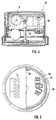
- FIG. 1 shows a water meter 1 with a first housing area 2, in which the volume or quantity measuring device 3 is arranged, and with a second housing area 4, which in the exemplary embodiment shown contains a mechanical counting device 5.
- a transmitter device 6 is arranged in the housing area 4, comprising a circuit board 7 on which all the elements required for radio operation and also a radio antenna are arranged.
- the transmitting device 6 is fed via the energy source 8, which is likewise integrated in the housing area 4.
- the operation of the water meter is now such that the measuring device 3 rotating by the water flow transmits its rotary movement, by suitable coupling, mechanically or magnetically, to a shaft 9 in the housing area 4, via which the counting device 5 is then driven in a manner not shown, and so on shows the volume flow or the amount consumed.
- a marking 10 is arranged on the counting device, which in the example shown is a roller counter, on one of the rollers, which, for example, consumes a quantity after each 360 ° rotation 100 liters indexed.
- a sensor 11 is arranged on the circuit board 7, which detects the marking 10 each time it passes through and accordingly sends a signal to the transmitting device 6.
- the signal and thus the counter reading are either stored and summed up in order to be sent in a stochastic or periodic sequence to a central reception system (not shown) independently of the detection signal will.
- the transmission operation can also take place depending on the count value signal, indicating the respective 100 liter period.
- Fig. 2 shows a water meter 22 of a second embodiment, which also has a mechanical counter 23.
- a reflex disk 24 is associated with this counting device (cf. FIG. 3), which is mechanically coupled to the counter 23 via a drive shaft 25 and which, if operated, is set in rotation by the counting device 23.
- the shaft 25 is coupled with, it always indicates 10 times the respective roller increment by one revolution, i.e., for example, when connected to the right 1 liter roller with one turn of the disc, a consumed amount of 10 liters specified.
- a reflective light barrier 26 is assigned opposite to the reflective light pane, which is covered with corresponding markings, which forms a light barrier with the reflective pane 24 and thus detects the corresponding markings on the reflective pane 24.
- a shield 27 is arranged, which shields any magnetic influence on the signal detection and transmission. After the markings have been detected, corresponding signals are emitted, depending on the operating mode, via the antenna 29 arranged in this example directly underneath an attachment plate 28 which covers the “inner life” of the water meter.
- FIG. 4 describes a third embodiment of a water meter 30, which also has a mechanical counter 31.
- the quantity interval is recorded here purely mechanically.
- a vertically standing shaft 32 is provided is driven either directly from the shaft 33 or indirectly via the roller counter 31 via a transmission gear, not shown.
- a switching cam 34 is arranged on the shaft 32 and actuates the microswitches 35 arranged on both sides when the shaft 32 rotates. Each time one of the switches is actuated, the flow of a predetermined quantity of water is indicated, the respective quantity interval depending on the rotational speed of the shaft 32 and can be adjusted by means of a corresponding configuration of the transmission gear. Instead of the two microswitches 35, only a single one could of course also be provided.
- a signal is also sent to the respective transmission device, after which the operating mode-dependent transmission of the respective count value takes place by means of the antenna 36, which is also arranged on the top in this example.
- FIG. 6 shows a further embodiment of a water meter 37, which also has a mechanical counter 38.
- a shaft 39 is coupled to this counting device 38 and is driven in rotation via the counting device 38.
- Two fork light barriers 41a, 41b are assigned to arm 40 (cf. FIG. 7), between which arm 40 is immersed when it rotates. With each immersion, the respective light barrier 41a or 41b is interrupted, so that the passage of the arm 40 is detected.
- the arrangement of two fork light barriers connected in series means that in the event of a backflow of water, if the arm 40 is rotated in the opposite direction, it will pass through the fork light barrier again and thus indicate a further, the predetermined quantity interval Signal is emitted, an incorrect measurement is prevented, since each signal can be resolved without a doubt.
- the arm 40 is first detected by the light barrier 41b, then by the light barrier 41a, and then runs backwards, the light barrier 41a again sends a signal, but this is not possible with normal forward drive would. In this way, such an erroneous signal can be rejected so that the quantity determination is not affected erroneously.
- the arrangement of two light barriers is of course also possible in the case of the embodiment of FIGS. 2 and 3, the double microswitch arrangement shown in FIGS. 4 and 5 also serving this purpose.
- a water meter with an electronic counting and / or display device is constructed in comparison to the mechanical examples shown in FIGS. 1 to 7 in such a way that an electronic counting device, for example with an LCD display, is arranged instead of the mechanical counting device.
- the operation of the same takes place via a control element, preferably a microprocessor, which is operated via an integrated battery.
- the measurement of the measuring device rotation is not usually done mechanically, but electrically via volume sensors.
- FIG. 8 The integration of the transmitter in such a water meter can now be seen in FIG. 8.
- the electronics of the conventional electronic water meter described are shown in area 12. This consists of a microprocessor 14 operated via a battery 13, which controls the LCD display 15 and is connected to additional elements such as the volume sensors 16, a switch button 17 and an external quartz crystal 18.
- the transmitter is connected to the microprocessor 14 Representing area 19, consisting of the radio device 20 and the transmitting antenna 21.
- the radio device 20 is directly connected to the microprocessor 14 and is controlled by the latter, for example at a predetermined time interval, and thus transmits the measurement results also supplied to the radio device 20 via the microprocessor 14 the antenna 21 to the central receiving system.
Abstract
Description
Die Erfindung betrifft einen Wasserzähler mit einer in einem ersten Gehäusebereich angeordneten Meßeinrichtung, insbesondere einem Flügelrad, zur Volumen- oder Mengenmessung und einer in einem zweiten Gehäusebereich angeordneten, mit der Meßeinrichtung zusammenwirkenden Zähl- und/oder Anzeigeeinrichtung, wobei die beiden Gehäusebereiche voneinander abgedichtet getrennt sind.The invention relates to a water meter with a measuring device arranged in a first housing area, in particular an impeller, for volume or quantity measurement and a metering and / or display device arranged in a second housing area and interacting with the measuring device, the two housing areas being separated from one another in a sealed manner .
Zum periodischen Ablesen von in Haushalten installierten Wasserzählern ist es stets erforderlich, daß die ablesende Person unweigerlich die Wohnung betritt, was für den Wohnungsinhaber, da dieser ja präsent sein muß, aufwendig und störend ist, ferner stellt dies auch einen Eingriff in seine Privatsphäre dar. Zum anderen wird aufgrund der steigenden Zahl von Ein-Personen-Haushalten es für die Versorgungs- und Abrechnungsunternehmen immer aufwendiger und schwieriger, die erforderlichen Ablesungen durchzuführen, da die Zahl der abzulesenden Wasserzähler kontinuierlich steigt, womit ein erheblicher Mehraufwand an Zeit, Personal und damit Kosten verbunden ist. Zwar sind bereits drahtgebundene Übertragungssysteme des Zählerwertes bekannt, jedoch besitzen diese den Nachteil, daß sie für den nachträglichen Einbau bzw. Installation infolge des sehr hohen Aufwands kaum geeignet ist.For periodic reading of water meters installed in households, it is always necessary that the person reading inevitably enters the apartment, which is expensive and annoying for the apartment owner, since this must be present, and this also constitutes an encroachment on his privacy. On the other hand, due to the increasing number of one-person households, it is becoming more and more complex and difficult for the supply and accounting companies to carry out the necessary readings, since the number of water meters to be read increases continuously, which means a considerable increase in time, personnel and thus costs connected is. Although wired transmission systems of the counter value are already known, they have the disadvantage that they are hardly suitable for retrofitting or installation due to the very high outlay.
Der Erfindung liegt somit die Aufgabe zugrunde, einen in einem Haushalt zu installierenden Wasserzähler zu schaffen, der es dem Versorgungsunternehmen erlaubt, den Zählerstand sicher und mit möglichst kleinem Aufwand ohne Betreten der jeweiligen Wohnung des Endkunden abzulesen, und der einfach auch im Nachrüstverfahren installierbar ist.The invention is therefore based on the object of creating a water meter to be installed in a household, which allows the utility company to read the meter reading safely and with as little effort as possible without entering the respective home of the end customer, and which can also be easily installed using the retrofitting method.
Zur Lösung dieser Erfindung ist bei einem Wasserzähler mit den eingangs genannten Merkmalen erfindungsgemäß eine mit dem Zählwerk zusammenwirkende, aus einer Energiequelle gespeiste funktechnische Sendeeinrichtung zum Aussenden des Zählerstandes an ein zentrales, entfernt angeordnetes Empfangssystem vorgesehen.To solve this invention, in a water meter with the features mentioned at the outset, a radio-technical transmitting device, which interacts with the meter and is fed from an energy source, is provided for transmitting the meter reading to a central, remote receiving system.
Der erfindungsgemäße Wasserzähler sendet somit den Zählerstand an ein separates Empfangssystem, das beispielsweise zentral im Flur, Keller oder dergleichen des Hauses, beispielsweise eines mehrstöckigen Mietshauses, angeordnet ist, wo der Ablesende einfachst und ohne Betreten der jeweiligen Wohnungen den Zählerstand ablesen kann. Der Zählerstand kann in stochastischer Folge oder periodisch mehrmals täglich übertragen werden. Ist beispielsweise das Haus komplett mit derartigen Wasserzählern ausgerüstet, können alle Zähler gleichzeitig am Empfangssystem abgelesen werden, ohne daß überhaupt jemand anwesend sein muß. Ein weiterer Vorteil der Funkübertragung, die bei periodischem Betrieb beispielsweise in vorbestimmten Zeit- oder Mengenintervallen, beispielsweise jede Stunde oder pro hundert Liter, erfolgt, ist die Reduzierung der Ablesefehler durch automatisch gesicherte Datenübertragung. Ferner herrscht, da ohne Aufwand in kürzeren Abständen, z. B. monatlich, abgelesen werden kann, eine größere Gerechtigkeit bei Tarif- oder Mieterwechsel. Da keinerlei zusätzlich in der Wohnung zu installierenden Elemente erforderlich sind, ist der Wasserzähler auch mühelos im Nachrüstverfahren installierbar.The water meter according to the invention thus sends the meter reading to a separate reception system, which is arranged, for example, centrally in the hallway, basement or the like of the house, for example a multi-storey apartment building, where the reader can easily read the meter reading without entering the respective apartments. The meter reading can be transmitted in a stochastic sequence or periodically several times a day. If, for example, the house is fully equipped with such water meters, all meters can be read simultaneously on the reception system without anyone having to be present. Another advantage of radio transmission, which takes place during periodic operation, for example at predetermined time or quantity intervals, for example every hour or per hundred liters, is the reduction of the reading errors through automatically secured data transmission. Furthermore, there is no effort in shorter intervals, for. B. monthly, can be read, greater justice when changing tariffs or tenants. Since no additional elements to be installed in the apartment are required, the water meter can also be easily installed using the retrofit method.
Um den Aufbau des erfindungsgemäßen Wasserzählers insbesondere für die Fertigung möglichst einfach zu gestalten, kann in weiterer Ausgestaltung der Erfindung vorgesehen sein, daß die Sendeeinrichtung eine die Sendeelemente, insbesondere eine Sendeantenne und gegebenenfalls die Zähl- und/oder Anzeigeeinrichtung tragende Platine aufweist, die einfachst in den oberen, zweiten Gehäusebereich eingesetzt wird.In order to make the structure of the water meter according to the invention as simple as possible, in particular for production, it can be provided in a further embodiment of the invention that the transmission device, in particular the transmission elements has a transmitting antenna and possibly the circuit board carrying the counting and / or display device, which is simply inserted into the upper, second housing area.
In weiterer Ausgestaltung der Erfindung kann bei einem erfindungsgemäßen Wasserzähler, dessen Zähl- und/oder Anzeigeeinrichtung eine mechanische Einrichtung, vorzugsweise ein Rollenzählwerk ist, erfindungsgemäß eine Sensoreinrichtung mit einem Sensor zur Erfassung einer an der mechanischen Zähleinrichtung angeordneten, ein bestimmtes gezähltes Volumen oder Menge indizierenden Markierung oder dergleichen vorgesehen sein, wobei die Aussendung der Funksignale gegebenenfalls in Abhängigkeit von der Sensorerfassung erfolgen kann. Dabei kann der Sensor erfindungsgemäß ein gegebenenfalls mittels einer separaten, vorzugsweise über ein Übersetzungsgetriebe angetriebenen Welle betätigter Micro-Schalter sein, alternativ dazu können auch ein Opto-Schalter oder ein Reed-Schalter Anwendung finden. Erfindungsgemäß haben sich Opto-Schalter, die als Lichtschranken ausgebildet sind, als äußerst zweckmäßig erwiesen, wobei vorzugsweise zwei derartige Lichtschranken hintereinander geschaltet sind. Jede Lichtschranke sendet zeitlich versetzt ein separates Signal bei Detektion der Markierung aus, so daß in dem Fall, wenn Wasser durch den Zähler zurückfließt, was eine Rückwärtsrotation des Zählwerks und damit der Markierung mit sich bringt, diese anhand der von den Lichtschranken herrührenden Signale ermittelt werden kann. Dies ist dahingehend von Vorteil, daß der jeweilige, von der Rückwärtsrotation herrührende Zählerwert, der ja das Meßergebnis verfälschen würde, nicht mit in die Berechnung eingeht. Insbesondere zur Realisation der Lichtschranken-Alternative hat es sich als zweckmäßig erwiesen, wenn erfindungsgemäß eine Welle vorgesehen ist, die die Markierung oder eine die Markierung tragende Scheibe rotierend antreibt und die mit dem Zählwerk gekoppelt ist, wobei die Markierung im Rahmen der Rotation mit dem Sensor in Wirkungsverbindung tritt.In a further embodiment of the invention, in the case of a water meter according to the invention, the counter and / or display device of which is a mechanical device, preferably a roller counter, according to the invention a sensor device with a sensor for detecting a marking, which is arranged on the mechanical metering device and indicates a certain counted volume or quantity or the like may be provided, the transmission of the radio signals possibly taking place as a function of the sensor detection. According to the invention, the sensor can be a micro switch that is optionally actuated by means of a separate shaft, preferably driven by a transmission gear, alternatively an opto switch or a reed switch can also be used. According to the invention, opto-switches which are designed as light barriers have proven to be extremely useful, preferably two such light barriers being connected in series. Each light barrier transmits a separate signal at a time when the marking is detected, so that in the event that water flows back through the counter, which results in a backward rotation of the counter and thus the marking, these are determined on the basis of the signals coming from the light barriers can. This is advantageous in that the respective counter value originating from the reverse rotation, which would falsify the measurement result, is not included in the calculation. In particular for realizing the light barrier alternative, it has proven to be expedient if, according to the invention, a shaft is provided which: drives the marking or a disk carrying the marking in rotation and which is coupled to the counter, the marking coming into operative connection with the sensor as part of the rotation.
Eine zweite erfindungsgemäße Ausführungsalternative eines Wasserzählers, der eine elektronische Zähl- und/oder Anzeigeeinrichtung, insbesondere eine LCD-Einrichtung aufweist, die ein sie steuerndes, aus einer Energiequelle gespeistes elektronisches Steuerelement, vorzugsweise einen Microprozessor, umfaßt, ist erfindungsgemäß dergestalt, daß die Steuereinrichtung mit dem Steuerelement in Verbindung steht, wobei das Steuerelement den Sendebetrieb steuert. Auf diese Weise kann die Sendeeinrichtung einfachst und ohne größeren Aufwand integriert werden.A second alternative embodiment of a water meter according to the invention, which has an electronic counting and / or display device, in particular an LCD device, which comprises an electronic control element, preferably a microprocessor, which controls it and is powered by an energy source, is designed according to the invention such that the control device also includes is connected to the control element, the control element controlling the transmission mode. In this way, the transmitter can be integrated easily and without great effort.
Im Rahmen der Erfindung kann ferner vorgesehen sein, daß die die Sendeeinrichtung speisende Energiequelle, insbesondere eine Batterie, im Inneren des Wasserzählers integriert ist, wobei bei dem die elektronische Zähl- und/oder Anzeigeeinrichtung aufweisenden Wasserzähler erfindungsgemäß die Speisung der Sendeeinrichtung aus der das Steuerelement und die elektronische Zähl- und/oder Anzeigeeinrichtung versorgenden Energiequelle erfolgt.Within the scope of the invention it can further be provided that the energy source feeding the transmission device, in particular a battery, is integrated in the interior of the water meter, with the water meter having the electronic metering and / or display device according to the invention supplying the transmission device from the control element and the energy supply supplying the electronic counter and / or display device takes place.
Um nun bereits installierte Wasserzähler der "alten" Art, also ohne Funkeinrichtung, mit einer derartigen aufzurüsten, oder um beispielsweise das Zählwerk zwecks Eichung oder dergleichen einfachst austauschen zu können, kann in weiterer Ausgestaltung der Erfindung vorgesehen sein, daß der zweite, die Zähl- und/oder Anzeigeeinrichtung und die Sendeeinrichtung und gegebenenfalls die Energiequelle und das Steuerelement tragende Gehäusebereich lösbar am ersten, die Meßeinrichtung enthaltenden Gehäusebereich angeordnet ist, so daß ein einfacher Austausch erfolgen kann.In order to retrofit already installed water meters of the "old" type, ie without a radio device, or to be able to simply replace the meter for calibration or the like, for example, it can be provided in a further embodiment of the invention that the second meter and / or display device and the transmitting device and optionally the housing area carrying the energy source and the control element, detachably on the first, the housing area containing the measuring device is arranged so that a simple exchange can take place.
Weitere Vorteile, Merkmale und Einzelheiten der Erfindung ergeben sich aus den im folgenden beschriebenen Ausführungsbeispielen sowie anhand der Zeichnungen. Dabei zeigen:
- Fig. 1
- einen Schnitt durch einen erfindungsgemäßen Wasserzähler mit mechanischer Zähl- und/oder Anzeigeeinrichtung,
- Fig. 2
- einen Schnitt durch einen erfindungsgemäßen Wasserzähler einer zweiten Ausführungsform mit mechanischer Zähl- und/oder Anzeigeeinrichtung,
- Fig. 3
- eine Aufsicht, teilweise im Schnitt, des Wasserzählers aus Fig. 2,
- Fig. 4
- einen Schnitt durch einen erfindungsgemäßen Wasserzähler einer dritten Ausführungsform mit mechanischer Zähl- und/oder Anzeigeeinrichtung,
- Fig. 5
- eine Aufsicht, teilweise im Schnitt, des Wasserzählers aus Fig. 4,
- Fig. 6
- einen Schnitt durch einen erfindungsgemäßen Wasserzähler einer vierten Ausführungsform mit mechanischer Zähl- und/oder Anzeigeeinrichtung,
- Fig. 7
- eine teilweise Seitenansicht des Wasserzählers aus Fig. 6 in Richtung der Pfeile VII - VII aus Fig. 6, und
- Fig. 8
- ein Einbindungsschema der Sendeeinrichtung in die Elektronik eines eine elektronische Zähl- und/oder Anzeigeeinrichtung aufweisenden Wasserzählers.
- Fig. 1
- 2 shows a section through a water meter according to the invention with a mechanical counting and / or display device,
- Fig. 2
- 2 shows a section through a water meter according to the invention of a second embodiment with a mechanical counting and / or display device,
- Fig. 3
- 3 shows a top view, partly in section, of the water meter from FIG. 2,
- Fig. 4
- 2 shows a section through a water meter according to the invention in a third embodiment with a mechanical counting and / or display device,
- Fig. 5
- 4 shows a top view, partly in section, of the water meter from FIG. 4,
- Fig. 6
- 4 shows a section through a water meter according to the invention in a fourth embodiment with a mechanical counting and / or display device,
- Fig. 7
- 6 in the direction of arrows VII - VII from FIG. 6, and
- Fig. 8
- an integration diagram of the transmission device in the electronics of an electronic meter and / or display device having a water meter.
Fig. 1 zeigt einen Wasserzähler 1 mit einem ersten Gehäusebereich 2, in dem die Volumen- oder Mengenmeßeinrichtung 3 angeordnet ist, und mit einem zweiten Gehäusebereich 4, der im gezeigten Ausführungsbeispiel eine mechanische Zähleinrichtung 5 beinhaltet. Im Gehäusebereich 4 ist eine Sendeeinrichtung 6 angeordnet, bestehend aus einer Platine 7, auf der sämtliche für den Funkbetrieb erforderlichen Elemente und auch eine Funkantenne angeordnet sind. Die Sendeeinrichtung 6 wird über die ebenfalls im Gehäusebereich 4 integrierte Energiequelle 8 gespeist. Der Betrieb des Wasserzählers ist nun derart, daß die durch den Wasserfluß rotierende Meßeinrichtung 3 ihre Drehbewegung durch geeignete Kupplung, mechanisch oder magnetisch, an eine Welle 9 im Gehäusebereich 4 überträgt, über welche dann die Zähleinrichtung 5 in nicht näher dargestellter Weise angetrieben wird und so den Volumenfluß oder den Mengenverbrauch anzeigt. Um nun den Zählerstand erfassen zu können, um ihn zu senden, ist an der Zähleinrichtung, bei der es sich im gezeigten Beispiel um ein Rollenzählwerk handelt, an einer der Rollen eine Markierung 10 angeordnet, die beispielsweise nach jeder 360°-Drehung einen Mengenverbrauch von 100 Litern indiziert. Auf der Platine 7 ist zur Erfassung dieser Markierung 10 ein Sensor 11 angeordnet, der bei jedem Durchgang der Markierung 10 diese detektiert und entsprechend ein Signal an die Sendeeinrichtung 6 gibt. In dieser wird das Signal und damit der Zählerstand entweder gespeichert und aufsummiert, um in stochastischer oder periodischer Folge an ein nicht dargestelltes zentrales Empfangssystem unabhängig von dem Erfassungssignal gesendet zu werden. Jedoch kann der Sendebetrieb auch in Abhängigkeit des Zählwertsignals, die jeweilige 100-Liter-Periode angebend, erfolgen.1 shows a
Fig. 2 zeigt einen Wasserzähler 22 einer zweiten Ausführungsform, der ebenfalls eine mechanische Zähleinrichtung 23 aufweist. Dieser Zähleinrichtung ist eine Reflexscheibe 24 zugeordnet (vgl. Fig. 3), die mechanisch mit dem Zählwerk 23 über eine Antriebswelle 25 gekoppelt ist, und die von der Zähleinrichtung 23, sofern diese betrieben wird, in Drehung versetzt wird. Je nachdem, an welcher der Zahlenrollen die Welle 25 angekoppelt ist, gibt sie durch eine Umdrehung immer das 10-fache des jeweiligen Rolleninkrements an, also beispielsweise wird bei Ankopplung an die rechte 1-Liter-Rolle mit einer Scheibenumdrehung eine verbrauchte Menge von 10 Litern angegeben. Der Reflexlichtscheibe, die mit entsprechenden Markierungen belegt ist, ist eine Reflexlichtschranke 26 gegenüberstehend zugeordnet, welche mit der Reflexscheibe 24 eine Lichtschranke bildet und so die entsprechenden Markierungen auf der Reflexscheibe 24 detektiert. Im Bereich der Reflexlichtschranke ist eine Abschirmung 27 angeordnet, die jegliche magnetische Beeinflussung der Signalerfassung und Übertragung abschirmt. Nach erfolgter Detektion der Markierungen werden entsprechende Signale je nach Betriebsmodus über die in diesem Beispiel direkt unterhalb eines das "Innenleben" des Wasserzählers abdeckenden Aufsteckschildes 28 angeordnete Antenne 29 ausgesendet.Fig. 2 shows a
In Fig. 4 ist eine dritte Ausführungsform eines Wasserzählers 30 beschrieben, der ebenfalls eine mechanische Zähleinrichtung 31 besitzt. Die Mengenintervallerfassung erfolgt hier jedoch auf rein mechanischem Wege. Zu diesem Zweck ist eine vertikal stehende Welle 32 vorgesehen, die über ein nichtdargestelltes Übersetzungsgetriebe entweder direkt von der Welle 33 oder indirekt über das Rollenzählwerk 31 angetrieben wird. An der Welle 32 ist ein Schaltnocken 34 angeordnet, der bei Drehung der Welle 32 die beidseitig angeordneten Mikroschalter 35 betätigt. Mit jeder Betätigung eines der Schalter ist der Durchfluß einer vorbestimmten Wassermenge indiziert, wobei das jeweilige Mengenintervall von der Drehgeschwindigkeit der Welle 32 abhängt und durch entsprechende Ausgestaltung des Übersetzungsgetriebes eingestellt werden kann. Anstelle der beiden Mikroschalter 35 könnte selbstverständlich auch nur ein einzelner vorgesehen sein. Nach erfolgter Betätigung des jeweiligen Schalters wird auch hier ein Signal an die jeweilige Sendeeinrichtung gegeben, wonach die betriebsmodusabhängige Aussendung des jeweiligen Zählwertes mittels der auch in diesem Beispiel oberseitig angebrachten Antenne 36 erfolgt.FIG. 4 describes a third embodiment of a
Fig. 6 zeigt eine weitere Ausführungsform eines Wasserzählers 37, der ebenfalls eine mechanische Zähleinrichtung 38 aufweist. An diese Zähleinrichtung 38 ist eine Welle 39 angekoppelt, die über die Zähleinrichtung 38 rotierend angetrieben wird. Am hinteren Ende ist ein senkrecht zur Welle 39 stehender Arm 40 angeordnet, der durch die Wellenrotation eine Kreisbewegung beschreibt. Dem Arm 40 sind zwei Gabellichtschranken 41a, 41b zugeordnet (vgl. Fig. 7), zwischen die der Arm 40 bei Drehung eintaucht. Mit jedem Eintauchen wird die jeweilige Lichtschranke 41a bzw. 41b unterbrochen, so daß der Durchlauf des Armes 40 detektiert wird. Durch die hintereinander geschaltete Anordnung zweier Gabellichtschranken wird im Falle eines Wasserrückflusses, wenn der Arm 40 ja in entgegengesetzte Richtung gedreht wird, dieser die Gabellichtschranke nochmals durchläuft und so ein weiteres, das vorbestimmte Mengenintervall indizierendens Signal abgegeben wird, eine fehlerhafte Messung verhindert, da jedes Signal zweifelsfrei aufgelöst werden kann. Dies hat zur Folge, daß, wenn der Arm 40 beim Durchgang zunächst von der Lichtschranke 41b, anschließend von der Lichtschranke 41a detektiert wird, und er anschließend rückwärts läuft, wiederum die Lichtschranke 41a als nächste ein Signal sendet, was jedoch bei normalem Vorwärtstrieb nicht möglich wäre. Auf diese Weise kann ein derart fehlerhaftes Signal ausgesondert werden, so daß die Mengenbestimmung davon nicht fehlerhaft beeinflußt wird. Die Anordnung zweier Lichtschranken ist selbstverständlich auch im Falle der Ausführungsform der Fig. 2 und 3 möglich, wobei auch die in den Fig. 4 und 5 gezeigte doppelte Microschalteranordnung diesem Zweck dienen kann.6 shows a further embodiment of a
Ein Wasserzähler mit elektronischer Zähl- und/oder Anzeigeeinrichtung ist im Vergleich zu den in den Fig. 1 bis 7 gezeigten mechanischen Beispielen derart aufgebaut, daß anstelle der mechanischen Zähleinrichtung eine elektronische Zähleinrichtung beispielsweise mit einer LCD-Anzeige angeordnet ist. Der Betrieb derselben erfolgt über ein Steuerelement, vorzugsweise einen Microprozessor, der über eine integrierte Batterie betrieben wird. Weiterhin erfolgt die Erfassung der Meßeinrichtungsrotation nicht in der Regel mechanisch, sondern elektrisch über Volumensensoren. Die Einbindung der Sendeeinrichtung in einen derartigen Wasserzähler ist nunmehr Fig. 8 zu entnehmen. Dabei ist im Bereich 12 die Elektronik des beschriebenen herkömmlichen elektronischen Wasserzählers dargestellt. Diese besteht aus einem über eine Batterie 13 betriebenen Microprozessor 14, der die LCD-Anzeige 15 steuert und mit zusätzlichen Elementen wie den Volumensensoren 16, einer Schalttaste 17 und einem externen Schwingquarz 18 in Verbindung steht. Dem Microprozessor 14 zugeschaltet ist der die Sendeeinrichtung darstellende Bereich 19, bestehend aus der Funkeinrichtung 20 und der Sendeantenne 21. Die Funkeinrichtung 20 steht direkt mit dem Microprozessor 14 in Verbindung und wird von diesem beispielsweise in einem vorbestimmten Zeittakt gesteuert und sendet so die der Funkeinrichtung 20 ebenfalls über den Microprozessor 14 zugeführten Meßergebnisse über die Antenne 21 an das zentrale Empfangssystem.A water meter with an electronic counting and / or display device is constructed in comparison to the mechanical examples shown in FIGS. 1 to 7 in such a way that an electronic counting device, for example with an LCD display, is arranged instead of the mechanical counting device. The operation of the same takes place via a control element, preferably a microprocessor, which is operated via an integrated battery. Furthermore, the measurement of the measuring device rotation is not usually done mechanically, but electrically via volume sensors. The integration of the transmitter in such a water meter can now be seen in FIG. 8. The electronics of the conventional electronic water meter described are shown in
Claims (13)
Applications Claiming Priority (2)
| Application Number | Priority Date | Filing Date | Title |
|---|---|---|---|
| DE4428996 | 1994-08-16 | ||
| DE4428996A DE4428996C2 (en) | 1994-08-16 | 1994-08-16 | water meter |
Publications (2)
| Publication Number | Publication Date |
|---|---|
| EP0701109A2 true EP0701109A2 (en) | 1996-03-13 |
| EP0701109A3 EP0701109A3 (en) | 1996-12-11 |
Family
ID=6525792
Family Applications (1)
| Application Number | Title | Priority Date | Filing Date |
|---|---|---|---|
| EP95112728A Withdrawn EP0701109A3 (en) | 1994-08-16 | 1995-08-12 | Watermeter |
Country Status (2)
| Country | Link |
|---|---|
| EP (1) | EP0701109A3 (en) |
| DE (1) | DE4428996C2 (en) |
Cited By (2)
| Publication number | Priority date | Publication date | Assignee | Title |
|---|---|---|---|---|
| EP1033578A2 (en) * | 1999-02-27 | 2000-09-06 | Horst Prof. Dr. Ziegler | Device for determining the rotation of a rotating element |
| EP2221585A1 (en) | 2009-02-23 | 2010-08-25 | Lorenz GmbH & Co. KG | Method for gathering consumption information |
Families Citing this family (15)
| Publication number | Priority date | Publication date | Assignee | Title |
|---|---|---|---|---|
| DE19632575A1 (en) * | 1996-08-13 | 1998-02-19 | Abb Patent Gmbh | Displacement type liquid flow meter |
| DE19723364B4 (en) * | 1997-06-04 | 2006-09-14 | Hydrometer Gmbh | Magnetic coupling for water meters with protection against external interference magnetic fields |
| DE29710249U1 (en) * | 1997-06-12 | 1998-10-08 | Raab Karcher Energy Services G | Device for recording and evaluating temperature-dependent consumption values |
| DE19755924C2 (en) * | 1997-12-17 | 2001-03-29 | Ifm Electronic Gmbh | Electronic evaluation device |
| DE19834009A1 (en) * | 1998-07-28 | 2000-02-24 | Micro Sensys Gmbh | Method to detect and confirm gas, water and electricity meters; uses data carrier, e.g. transponder, integrated on chip to provide computer with data from meter |
| DE19839116A1 (en) * | 1998-08-27 | 2000-03-02 | Horst Ziegler | System for controlling the consumption of a medium, especially a line-bound medium |
| DE19903789C1 (en) * | 1999-02-01 | 2000-08-03 | Hydrometer Gmbh | Communication-capable flow meter for liquids, especially water meters |
| DE19922603A1 (en) * | 1999-05-17 | 2000-11-23 | Elster Produktion Gmbh | Method and device for reading a consumer meter by a remote instrument is fitted with a remote instrument reading module to record consumption electronically and to pass on a data remote transmission link to a data pick-up device. |
| DE19923932C2 (en) * | 1999-05-26 | 2002-08-01 | Hydrometer Gmbh | Liquid meter with multifunctional measuring chamber cover |
| DE19939535C2 (en) * | 1999-08-20 | 2003-10-09 | Wiesemann & Theis Gmbh | Method for radio transmission of a status signal from a sensor |
| DE19957280A1 (en) * | 1999-11-29 | 2001-05-31 | Elster Produktion Gmbh | Counter with additional module |
| DE10006804C2 (en) | 2000-02-15 | 2003-09-04 | Berg Prototypen & Design Roland | Reflector for a lighting device and its use in flat lamp chambers, especially vehicle signal lamps |
| DE10214418A1 (en) * | 2002-03-30 | 2003-10-09 | Abb Patent Gmbh | Volume flow meter, especially water meter, has openings in meter mechanism housing matched to shape and size of signal pick up and transmitter module |
| DE102006020030A1 (en) * | 2006-04-26 | 2007-11-08 | IAD Gesellschaft für Informatik, Automatisierung und Datenverarbeitung mbH | Data acquisition and control system with data transmission over radio links and electrical energy distribution networks and method therefor |
| DE202013001852U1 (en) * | 2013-02-27 | 2014-02-28 | Christian Gradischnik | Device for detecting a flow |
Family Cites Families (17)
| Publication number | Priority date | Publication date | Assignee | Title |
|---|---|---|---|---|
| DE1775155C3 (en) * | 1968-07-10 | 1978-06-08 | Dr.Ing.H.C. F. Porsche Ag, 7000 Stuttgart | Bevel gearbox with synchronizing device |
| DE2221371B2 (en) * | 1972-05-02 | 1974-04-25 | Siemens Ag, 1000 Berlin U. 8000 Muenchen | Device for the wireless transmission of a measured value from a transducer to an evaluation circuit |
| DE2419081C3 (en) * | 1974-04-20 | 1979-02-15 | Bien, Reinhold, 6701 Ruppertsberg | Device for contactless transmission of measured values |
| DE2551882C3 (en) * | 1975-11-19 | 1979-03-08 | Fraunhofer-Gesellschaft Zur Foerderung Der Angewandten Forschung E.V., 8000 Muenchen | Device for wireless remote transmission of the speed of a rotating part |
| DE2616323A1 (en) * | 1976-04-14 | 1977-10-27 | Kueppers Karl | Flowmeter for very small flows - rotates plate in field of coil, damping it at times so that oscillator operation stop |
| US4119948A (en) * | 1976-04-29 | 1978-10-10 | Ernest Michael Ward | Remote meter reading system |
| DE2854199A1 (en) * | 1978-12-15 | 1980-06-26 | Vdo Schindling | DEVICE FOR TRANSMITTING MEASURED VALUES |
| DE2935965B2 (en) * | 1979-09-06 | 1981-07-16 | Kurt 2110 Buchholz Fritze | Arrangement for telemetric monitoring of moving machine parts. |
| DE3241222C2 (en) * | 1982-11-09 | 1985-03-21 | Hans 6908 Wiesloch Engelmann | Device for measuring the speed and possibly the direction of rotation of an impeller of an impeller flow meter for electrolytic liquids |
| FR2543292B1 (en) * | 1983-03-21 | 1986-10-10 | Pont A Mousson | DEVICE FOR MEASURING THE ROTATION OF A TURBINE OF FLUID FLOW METERS |
| JPS60135822A (en) * | 1983-12-26 | 1985-07-19 | Ricoh Co Ltd | Automatic checking device of water service meter |
| DE3519215A1 (en) * | 1985-04-13 | 1986-10-16 | Ziegler, Horst, Prof. Dr., 4790 Paderborn | PROBE, ESPECIALLY FOR USE ON A WING WHEEL FLOW METER |
| US4940976A (en) * | 1988-02-05 | 1990-07-10 | Utilicom Inc. | Automated remote water meter readout system |
| ES2009665A6 (en) * | 1988-11-04 | 1989-10-01 | Perez Lago Alfredo | Fluid flow volume measurement and billing system |
| JPH03215713A (en) * | 1990-01-20 | 1991-09-20 | Kimmon Mfg Co Ltd | Transmitter for automatic power generation type water supply meter |
| US5214587A (en) * | 1990-11-28 | 1993-05-25 | Green Richard G | Device for monitoring utility usage |
| DE4123043A1 (en) * | 1991-07-12 | 1993-01-21 | Ingo Dohmann | Fluid dispensing system throughput display e.g. for oil, hydraulic fluid - has throughput detectors with transmitters and independently positioned mobile display device with receiver |
-
1994
- 1994-08-16 DE DE4428996A patent/DE4428996C2/en not_active Revoked
-
1995
- 1995-08-12 EP EP95112728A patent/EP0701109A3/en not_active Withdrawn
Non-Patent Citations (1)
| Title |
|---|
| None |
Cited By (3)
| Publication number | Priority date | Publication date | Assignee | Title |
|---|---|---|---|---|
| EP1033578A2 (en) * | 1999-02-27 | 2000-09-06 | Horst Prof. Dr. Ziegler | Device for determining the rotation of a rotating element |
| EP1033578A3 (en) * | 1999-02-27 | 2000-11-02 | Horst Prof. Dr. Ziegler | Device for determining the rotation of a rotating element |
| EP2221585A1 (en) | 2009-02-23 | 2010-08-25 | Lorenz GmbH & Co. KG | Method for gathering consumption information |
Also Published As
| Publication number | Publication date |
|---|---|
| DE4428996C2 (en) | 1997-04-30 |
| EP0701109A3 (en) | 1996-12-11 |
| DE4428996A1 (en) | 1996-02-29 |
Similar Documents
| Publication | Publication Date | Title |
|---|---|---|
| EP0701109A2 (en) | Watermeter | |
| EP0180880A2 (en) | Display detection device for a watch, in particular a radio watch | |
| EP1012430A1 (en) | Process and device for controlling the closure of locks | |
| WO2006114211A1 (en) | Multiple- pane window with an electrical built-in element | |
| DE19849108A1 (en) | Encoder | |
| DE2838056B1 (en) | Locking system for use locks with a key signal transmitter and a key signal receiver | |
| DE3929879A1 (en) | Multifunctional security parking card - includes finger-pressure actuated radio transmitter alarm sender | |
| EP0924379A2 (en) | Tape drum for a darkening device | |
| DE102015011299A1 (en) | Arrangement for closure monitoring | |
| DE4309006A1 (en) | Wireless data transmission device | |
| EP1890116B1 (en) | Tamperproof liquid flow meter | |
| EP1026481B1 (en) | Communication capable flowrate counter for liquids, in particular water counter | |
| EP0001976B1 (en) | Coin testing assembly for electronic parking lot meters | |
| DE8432847U1 (en) | Pointer position detection device for a clock, in particular a radio clock | |
| EP0513633B1 (en) | Alarm clock | |
| EP0650107A1 (en) | Control system for motorized drives | |
| EP1050747A2 (en) | Device for determining a volume of a gas stream | |
| DE60108397T2 (en) | CONSUMPTION COUNTERS | |
| WO1994027256A1 (en) | Toll-recording system for use in urban streets and traffic areas | |
| DE102007054462B4 (en) | Door drive with an angle detection of the closer shaft | |
| DE102016217549B4 (en) | combination lock | |
| EP0701724A1 (en) | Device for payment of parking fees | |
| EP0317819A2 (en) | Rotating counting mechanism, in particular for a gas meter | |
| EP0663598A2 (en) | Means for determining current pulses of lightning conductors or similar | |
| DE19632575A1 (en) | Displacement type liquid flow meter |
Legal Events
| Date | Code | Title | Description |
|---|---|---|---|
| PUAI | Public reference made under article 153(3) epc to a published international application that has entered the european phase |
Free format text: ORIGINAL CODE: 0009012 |
|
| AK | Designated contracting states |
Kind code of ref document: A2 Designated state(s): AT CH DE FR GB IT LI |
|
| PUAL | Search report despatched |
Free format text: ORIGINAL CODE: 0009013 |
|
| AK | Designated contracting states |
Kind code of ref document: A3 Designated state(s): AT CH DE FR GB IT LI |
|
| 17P | Request for examination filed |
Effective date: 19970120 |
|
| 17Q | First examination report despatched |
Effective date: 20000823 |
|
| STAA | Information on the status of an ep patent application or granted ep patent |
Free format text: STATUS: THE APPLICATION IS DEEMED TO BE WITHDRAWN |
|
| 18D | Application deemed to be withdrawn |
Effective date: 20010103 |