EP0702305A1 - Disk memory apparatus - Google Patents
Disk memory apparatus Download PDFInfo
- Publication number
- EP0702305A1 EP0702305A1 EP95114329A EP95114329A EP0702305A1 EP 0702305 A1 EP0702305 A1 EP 0702305A1 EP 95114329 A EP95114329 A EP 95114329A EP 95114329 A EP95114329 A EP 95114329A EP 0702305 A1 EP0702305 A1 EP 0702305A1
- Authority
- EP
- European Patent Office
- Prior art keywords
- disk memory
- data
- disk
- memory apparatus
- drive
- Prior art date
- Legal status (The legal status is an assumption and is not a legal conclusion. Google has not performed a legal analysis and makes no representation as to the accuracy of the status listed.)
- Withdrawn
Links
Images


Classifications
-
- G—PHYSICS
- G06—COMPUTING; CALCULATING OR COUNTING
- G06F—ELECTRIC DIGITAL DATA PROCESSING
- G06F12/00—Accessing, addressing or allocating within memory systems or architectures
- G06F12/02—Addressing or allocation; Relocation
- G06F12/08—Addressing or allocation; Relocation in hierarchically structured memory systems, e.g. virtual memory systems
- G06F12/12—Replacement control
- G06F12/121—Replacement control using replacement algorithms
- G06F12/122—Replacement control using replacement algorithms of the least frequently used [LFU] type, e.g. with individual count value
-
- G—PHYSICS
- G06—COMPUTING; CALCULATING OR COUNTING
- G06F—ELECTRIC DIGITAL DATA PROCESSING
- G06F12/00—Accessing, addressing or allocating within memory systems or architectures
- G06F12/02—Addressing or allocation; Relocation
- G06F12/08—Addressing or allocation; Relocation in hierarchically structured memory systems, e.g. virtual memory systems
- G06F12/0802—Addressing of a memory level in which the access to the desired data or data block requires associative addressing means, e.g. caches
- G06F12/0866—Addressing of a memory level in which the access to the desired data or data block requires associative addressing means, e.g. caches for peripheral storage systems, e.g. disk cache
-
- G—PHYSICS
- G06—COMPUTING; CALCULATING OR COUNTING
- G06F—ELECTRIC DIGITAL DATA PROCESSING
- G06F3/00—Input arrangements for transferring data to be processed into a form capable of being handled by the computer; Output arrangements for transferring data from processing unit to output unit, e.g. interface arrangements
- G06F3/06—Digital input from, or digital output to, record carriers, e.g. RAID, emulated record carriers or networked record carriers
- G06F3/0601—Interfaces specially adapted for storage systems
-
- G—PHYSICS
- G11—INFORMATION STORAGE
- G11B—INFORMATION STORAGE BASED ON RELATIVE MOVEMENT BETWEEN RECORD CARRIER AND TRANSDUCER
- G11B19/00—Driving, starting, stopping record carriers not specifically of filamentary or web form, or of supports therefor; Control thereof; Control of operating function ; Driving both disc and head
- G11B19/02—Control of operating function, e.g. switching from recording to reproducing
-
- G—PHYSICS
- G11—INFORMATION STORAGE
- G11B—INFORMATION STORAGE BASED ON RELATIVE MOVEMENT BETWEEN RECORD CARRIER AND TRANSDUCER
- G11B20/00—Signal processing not specific to the method of recording or reproducing; Circuits therefor
- G11B20/10—Digital recording or reproducing
-
- G—PHYSICS
- G06—COMPUTING; CALCULATING OR COUNTING
- G06F—ELECTRIC DIGITAL DATA PROCESSING
- G06F3/00—Input arrangements for transferring data to be processed into a form capable of being handled by the computer; Output arrangements for transferring data from processing unit to output unit, e.g. interface arrangements
- G06F3/06—Digital input from, or digital output to, record carriers, e.g. RAID, emulated record carriers or networked record carriers
- G06F2003/0697—Digital input from, or digital output to, record carriers, e.g. RAID, emulated record carriers or networked record carriers device management, e.g. handlers, drivers, I/O schedulers
-
- G—PHYSICS
- G06—COMPUTING; CALCULATING OR COUNTING
- G06F—ELECTRIC DIGITAL DATA PROCESSING
- G06F2212/00—Indexing scheme relating to accessing, addressing or allocation within memory systems or architectures
- G06F2212/31—Providing disk cache in a specific location of a storage system
- G06F2212/312—In storage controller
-
- Y—GENERAL TAGGING OF NEW TECHNOLOGICAL DEVELOPMENTS; GENERAL TAGGING OF CROSS-SECTIONAL TECHNOLOGIES SPANNING OVER SEVERAL SECTIONS OF THE IPC; TECHNICAL SUBJECTS COVERED BY FORMER USPC CROSS-REFERENCE ART COLLECTIONS [XRACs] AND DIGESTS
- Y02—TECHNOLOGIES OR APPLICATIONS FOR MITIGATION OR ADAPTATION AGAINST CLIMATE CHANGE
- Y02D—CLIMATE CHANGE MITIGATION TECHNOLOGIES IN INFORMATION AND COMMUNICATION TECHNOLOGIES [ICT], I.E. INFORMATION AND COMMUNICATION TECHNOLOGIES AIMING AT THE REDUCTION OF THEIR OWN ENERGY USE
- Y02D10/00—Energy efficient computing, e.g. low power processors, power management or thermal management
Definitions
- the present invention relates to a disk memory apparatus, and more particularly to a disk memory apparatus having a memory to store a portion of data in a disk memory thereof.
- a conventional disk memory apparatus (e.g., a hard disk apparatus, an optical disk memory apparatus and a flexible memory apparatus) includes a disk memory drive to rotate a disk memory.
- the disk memory drive begins to rotate the disk memory.
- the rotational speed of the disk memory increases to reach a predetermined rotational speed (e.g., 1,200 to 3,600 rpm in the case of certain Flexible Disk Drive or other operational speeds in the case of other drive devices).
- the disk memory apparatus sends to an information processing device (e.g., a host computer) a ready signal indicating that the disk memory apparatus is ready to be accessed.
- the information processing device Upon receiving the ready signal, the information processing device begins to access the disk memory apparatus.
- the information processing device cannot access the disk memory apparatus until the rotational speed of the disk memory reaches the predetermined speed (e.g., an operational speed).
- Another conventional disk memory apparatus has a disk cache to reduce access time.
- the disk cache stores a portion of data in the disk memory.
- the disk memory apparatus reads the data out of the disk cache in lieu of the disk memory. This reduces the access time of the data because the access time of the disk cache is by far shorter than that of the disk memory.
- the contents of the disk cache is updated according to a replacement policy such as least recently used (LRU) so as to increase the hit ratio of the disk cache.
- a replacement policy such as least recently used (LRU) so as to increase the hit ratio of the disk cache.
- the information processing device has to wait for accessing data until the rotational speed of the disk memory reaches the predetermined value.
- One object of the present invention is to allow a disk memory apparatus to send data before the disk memory becomes ready to be accessed. Specifically, the disk memory apparatus sends the data before the rotational speed of the disk memory reaches a predetermined speed (e.g., an operational speed).
- a predetermined speed e.g., an operational speed
- Another object of the present invention is to allow a disk memory apparatus to send data soon after the power is turned on.
- Another object of the present invention is to allow a disk memory apparatus to send data soon after the disk memory drive is restarted.
- Another object of the present invention is to select data frequently accessed soon after the power is turned on.
- Another object of the present invention is to select data frequently accessed after the disk memory apparatus is idle for a predetermined period of time.
- Another object of the present invention is to enhance the lifetime of the disk memory apparatus.
- Another object of the present invention is to save electrical power supplied to the disk memory apparatus.
- a disk memory apparatus is coupled with an information processing device and supplied with electrical power.
- the disk memory apparatus includes a disk memory drive, a non-volatile memory and a controller.
- the disk memory drive stores data therein.
- the non-volatile memory stores a portion of data contained in the disk memory drive and maintains contents thereof when the electrical power is removed.
- the controller transfers data in the nonvolatile memory to the information processing device when the disk memory drive is not ready for data reproduction.
- the controller may transfer the data when the disk memory device is not ready for data reproduction after turning on of the electrical power.
- the nonvolatile memory may store data requested by the information processing device when the electrical power is turned on.
- the disk memory apparatus may include shutdown means for stopping the disk memory drive after the disk memory apparatus is idle for a predetermined period of time.
- the controller may transfer the data when the disk memory drive is not ready due to stoppage thereof by the shutdown means.
- the controller may select data to be stored in the nonvolatile memory according to statistics on data accessed by the information processing device. More specifically, the controller may store in the nonvolatile memory history information indicating a history of data accessed by the information processing device, and the controller may select data to be stored in the nonvolatile memory according to the history information. The controller may select data to be stored in the nonvolatile memory according to a frequency of access to the data.
- the nonvolatile memory may include a flash memory.
- a disk memory apparatus 1 is coupled to an information processing device (e.g., a computer) 2.
- the disk memory apparatus 1 sends to the computer 2 a ready signal indicating that the disk memory apparatus is ready to handle requests from the computer 2.
- the computer 2 After receiving the ready signal, the computer 2 requests data reproduction and data recording to the disk memory apparatus 1 by sending commands to the disk memory apparatus 1.
- the data is recorded and reproduced in blocks each including 512 bytes. Each block is assigned a block address.
- the computer 2 sends the block address along with the commands to identify the data block to be accessed.
- the disk memory apparatus 1 is supplied with electrical power 100.
- the electrical power is turned on and turned off by the computer 2 or the operator.
- the disk memory apparatus 1 includes an input-output processor 11, a main processor 15, a non-volatile memory 16, a buffer memory 14, a disk memory drive 12 and a disk memory drive control circuit 17.
- the electrical power 100 is supplied to those elements in the disk memory apparatus 1.
- the input-output processor 11 receives the commands from the computer 2.
- the input-output processor 11 controls the data transfer between the computer 2 and the non-volatile memory 16 and between the computer 2 and the buffer memory 14.
- the input-output processor 11 sends the ready signal to the computer 2.
- the operation of the input-output processor 11 is controlled by the main processor 15.
- the disk memory drive 12 (e.g., a hard disk drive, an optical disk drive or a flexible disk drive) includes a disk memory (e.g., a hard disk, an optical disk or a flexible disk) rotated by a spindle motor.
- the disk memory drive includes a head for reproducing data from and/or recording data in the disk memory.
- the disk memory drive control circuit 13 controls the operation of the disk memory drive 12.
- the disk memory drive control circuit 13 reads data out of the disk memory drive 12 and stores the data into the buffer memory 14.
- the disk memory drive control circuit 13 reads data out of the buffer memory 14 and writes the data in the disk memory drive 12.
- the disk memory drive control circuit 13 sends a signal to the main processor when the disk memory drive becomes ready to perform data reproduction and/or data recording. More specifically, the disk memory drive control circuit 13 sends the signal when the rotational speed of the disk memory in the disk memory drive 12 reaches a predetermined value.
- the predetermined value may be set by the designer according to the designer's requirements.
- the disk memory drive control circuit 13 includes a shutdown circuit 17.
- the shutdown circuit 17 suspends the rotation of the spindle motor in the disk memory drive 12 when receiving a shutdown signal from the main processor 15. In this exemplary embodiment, the shutdown circuit 17 turns off the power of the disk memory drive 12.
- the non-volatile memory 16 which is a key feature of the present invention, stores data sent from the main processor 15.
- the non-volatile memory 16 retains the contents thereof even if the electrical power 100 is turned off.
- the non-volatile memory 16 includes a flash memory.
- a random access memory having a back-up battery can also be used as the non-volatile memory 16.
- non-volatile memory does not include disk memories such as a magnetic disk memory and an optical disk memory.
- the non-volatile memory 16 has an error checking/correcting function using the cycle redundancy check (CRC) as an exemplary error detection algorithm.
- CRC cycle redundancy check
- the main processor 15 executes programs stored in a memory (not shown in the figure). By executing the programs, the main processor 15 controls the operation of the input-output processor 11 and the disk memory drive control circuit 13. The main processor 15 also accesses the non-volatile memory 16 and the buffer memory 14.
- the main processor 15 includes a shutdown timer T.
- the contents of the shutdown timer T is reset to a predetermined value when the disk memory drive 12 is accessed.
- the contents of the shutdown timer T is decremented while the disk memory drive 12 is idle.
- the shutdown timer T generates a signal when a predetermined period of time has passed after the last resetting. Upon receiving this signal, the main processor 15 sends the shutdown signal to the shutdown circuit 17.
- main processor has the functions disclosed below.
- the main processor 15 stores information of a history of the data blocks accessed by the computer 2 in the non-volatile memory 16.
- the main processor 15 selects part of the data in the disk memory to be stored in the non-volatile memory 16 according to the aforementioned information.
- the main processor 15 transfers data in the non-volatile memory 16 to the computer 2 instead of the data in the disk memory of drive 12.
- the main processor 15 suspends the rotation of the spindle motor in the disk memory drive 12.
- the non-volatile memory 16 has a flag area 21, a data block table area 22, a data block storage area 23 and a statistics area 24.
- the data block storage area 23 includes first to fifth segment areas 231 to 235.
- the flag area 21 stores a flag indicating whether effective data exists in the non-volatile memory 16 or not.
- the flag includes 2 bytes. The flag indicates that effective data exists in the non-volatile memory 16 when the value of the flag is set to 5555h by hexadecimal.
- the data block table area 22 stores information indicating a relationship between the data blocks in the data block storage area 23 and those in the disk memory.
- the data block storage area 23 stores parts (i.e., copies) of data blocks in the disk memory.
- the data block storage area 23 is divided into first to fifth segment areas 231 to 235.
- the first and second segment areas 231 and 232 store data blocks frequently accessed by the computer 2 soon after the power 100 is turned on.
- the third to fifth segment areas 233 to 235 store data blocks frequently accessed by the computer 2 after the disk memory drive 12 is idle for the predetermined period of time. The method of selecting data blocks to be stored in the data block storage area 23 is described below.
- the statistics area stores information of a history of data blocks accessed by the computer 2.
- the data block table area 22 includes first to fifth index areas 31 to 35 corresponding to the first to fifth segment areas 231 to 235, respectively.
- Each of the index areas 31 to 35 includes an availability area 310, a segment address area 311, a first block address area 312 and a last block address area 313.
- the availability area 310 stores information indicating whether the corresponding segment area stores data or not.
- the segment address area 311 stores the address of the corresponding segment area in the non-volatile memory 16.
- the first and last block address areas 312 and 313 store the block address of the data stored in the corresponding segment area.
- a plurality of data blocks may be stored in one segment area. In this case, the first and last block address areas 312 and 313 store the block addresses of the first and last data blocks, respectively.
- the statistics area 24 includes an weight table area 5 and areas 41 and 42.
- the area 41 stores information about data accesses after the power 100 is turned on.
- the area 42 stores information about data accesses after the shutdown of the disk memory drive 12.
- the area 41 includes first to eighth entry areas 411 to 418.
- Each of the entry areas 411 to 418 includes first and last block address areas 4111 and 4112.
- the entry areas 411 to 418 store first and last block addresses of the data recently accessed by the computer 2 after the power 100 is turned on.
- the area 42 includes first to eighth entry areas 421 to 428.
- Each of the entry areas 421 to 428 includes first and last block address areas 4211 and 4212.
- the entry areas 421 to 428 store first and last block addresses of the data recently accessed by the computer 2 after the shutdown of the disk memory drive 12.
- the weight table area 5 includes a plurality of ranking areas 51 to 5n.
- Each of ranking areas 51 to 5n includes first and last block address areas 511 and 512.
- the ranking areas 51 to 5n store the first and last address of the data in the data block storage area 23 in descending order of the weight indicating access frequency.
- the operation of the main processor 15 is implemented by a program stored in a memory (not shown in the figures).
- step A01 when the power 100 is turned on, the main processor 15 and the other circuits are initialized (step A01). After the initialization, the main processor 100 sends the shutdown signal to the shutdown circuit 17.
- the main processor 15 determines whether or not effective data is stored in the data block storage area 23 by checking the contents of the flag area 21 (step A02).
- step B01 When effective data is not stored, the program branches to step B01 to prepare starting of the disk memory drive 12.
- the input-output processor 11 sends to the computer 2 a ready signal indicating that the disk memory apparatus 1 is in an accessible state (step A03).
- the main processor 15 waits for a command from the computer 2 (step A04). Upon receiving the command from the computer 2, it is determined whether or not the corresponding command is a request for reproducing (step A05). When the command is not a request for reproducing, the program branches to step E01.
- the program determines whether or not the requested data blocks are stored in the non-volatile memory 16 by referring to the data block table area 22 (steps A06 and A07).
- step D01 When the requested data blocks are not in the non-volatile memory 16, the program branches to step D01 to read the requested data blocks out of the disk memory drive 12.
- step A08 When the requested data blocks are in the non-volatile memory 16, errors in the data blocks are checked by CRC (step A08). When an error is detected, the program stops to transfer the data blocks in the non-volatile memory 16 and branches to step D01 to read the data block out of the disk memory drive 12.
- the main processor 15 transfers the corresponding data block to the computer 2 from the non-volatile memory 16 through the input-output processor 11 (step A09). This means that the requested data block can be transferred to the computer 2 even before the disk memory drive 12 is ready for data reproduction.
- step A10 After transferring the data block, the program executes an access statistics process (step A10).
- the main processor 15 turns off the shutdown signal to start the disk memory drive 12 (step B02). Thereafter, the main processor 15 waits for a signal from the disk memory drive 12 indicating that the disk memory drive 12 is ready to reproduce data.
- the program Upon receiving the signal through the disk memory drive control circuit 13, the program sends the ready signal to the computer 2 (step B04) to inform the computer 2 that the disk memory drive 12 is ready to reproduce data. Thereafter, the shutdown timer T is activated to start counting (step B06).
- the program branches to step C01.
- the main processor 15 controls the operation of the disk memory drive 12 such as the rotation of the spindle motor and the position of the head (step B07).
- the main processor 15 When the shutdown timer T informs that the predetermined period of time has lapsed, the main processor 15 outputs the shutdown signal to the shutdown circuit 17. Upon receiving the shutdown signal, the shutdown circuit 17 turns off the power supplied to the disk memory drive 12. When the power is turned off, the disk memory drive' control circuit 13 performs preparatory operations such as the positioning of the head or the like (steps B08, B09 and B10). This condition of the disk memory apparatus 1 is hereinafter referred to as a "power saving state". When the disk memory apparatus 12 is brought into the power saving state, the program branches to step A04 in Fig. 6 (step A11).
- disk memory drive 12 when disk memory drive 12 is not accessed for the predetermined time, the power supply of disk memory drive 12 is turned off to save power.
- the program determines whether or not the command sent from the computer 2 is a data reproduction request (step C02). When the command is not a data reproduction request, the program branches to step C08.
- the program determines whether or not the data blocks requested by the computer 2 are stored in the non-volatile memory 16 by referring to the data block table area 22 (steps C03 and C04). When the requested data blocks are not in the non-volatile memory 16, the program branches to step C09. In step C09, the program suspends the counting of the shutdown timer T and branches to step D08.
- step C05 When the requested data blocks are in the non-volatile memory 16, errors in the data blocks are checked by CRC (step C05). When an error is detected, the program branches to step C09 to read the data block out of the disk memory.
- the program transfers the corresponding data block to the computer 2 from the non-volatile memory 16 through the input-output processor 11 (step C06).
- step C06 After the data transfer in step C06, the program executes an access statistics process, which is described below (step C07). After the access statistics process, the program branches to step B12.
- the program turns off the shutdown signal to put the disk memory drive 12 in motion and waits until receiving a signal from the disk memory drive 12 indicating that it is ready for data reproduction (steps D02 and D03).
- the program transfers the requested data blocks in, disk memory drive 12 to the buffer memory 14 (step D04). If a data error is detected by an error inspection function of the buffer memory 14, a specified error process is executed and thereafter a process shown on and after step D07, as described below, is executed (steps D05 and D09).
- step D06 When an error is not detected, then the data stored in the buffer memory 14 is transferred to the computer 2 through the input-output processor 11 (step D06). Thereafter, the program executes the access statistical process (step D07) and branches to step B11 to execute steps after step B04 in Fig. 7.
- the program terminates the shutdown signal to put the disk memory drive 12 in motion and waits until receiving a signal from the disk memory drive 12 indicating that it is ready for data reproduction (steps E02 and E03). Upon receiving this signal, the program executes the operation instructed by the command from the computer 2 (step E04). Thereafter, the program branches to step B11 in Fig. 7.
- step F02 the program determines the number of accesses requested after the power is turned on. If the number is less than or equal to a predetermined threshold, the program branches to step F03. If the number exceeds the threshold, the program branches to step F05.
- the threshold which is a positive integer, is set considering the capacity of the non-volatile memory 16, the property of the computer 2 and so on. This determination limits the number of accesses that are taken into account when the program updates the contents of the non-volatile memory 16.
- step F05 the present access is registered in the entry area 411. Specifically, the first and last block addresses of the present access are stored in the first and last block address areas 4111 and 4112, respectively. The data previously stored in the entry areas 411 to 417 is moved to the entry areas 412 to 148, respectively. The data previously stored in the entry area 418 is deleted.
- step F06 the weight table area 5 is updated.
- the weights of data blocks registered in the area 41 are calculated.
- (9 - N)2 is the weight of the data block which is accessed N times before and registered in the entry area 41N.
- the data blocks are registered in the ranking areas 51 to 5n in the descending order of the weight thereof. That is, in the first and last data block address areas 511 and 512 is stored those of the data block having the greatest weight.
- step F07 the program determines whether or not the contents of the non-volatile memory 16 need to be updated. The detailed process of the determination is described below.
- the program determines the number Sg of the segment area for storing the data blocks frequently accessed soon after the power 100 is turned on.
- the number Sg is equal to 2 because the segment areas 231 and 232 are provided for this purpose.
- a third step comparing the first and last data block addresses in the data block table area 22 (Fig. 3) to those in the weight table area 5 (Fig. 5), the program determines whether or not the segment areas 231 and 232 stores all of the data blocks obtained in the second step. If all data blocks are stored, the program branches to step F04 and the access statistics process is terminated. If some of the data blocks are not stored, the program branches to step G01.
- step F03 when the program determines that the number of accesses after the power 100 is turned on exceeds the threshold, the program branches to step F03.
- step F03 the program determines whether or not the number of accesses after the shutdown of the disk memory drive 12 exceeds a predetermined threshold.
- the threshold is set taking into account the capacity of the non-volatile memory 16, the properties and characteristics of the computer 2 and so on. If the number of accesses exceeds the threshold, the program branches to step F03 and the access statistics process is terminated. If the number is less than or equal to the threshold, the program branches to step F08.
- steps F08 to F10 the program executes substantially the same operations as those of steps F05 to F07, respectively, with respect to the areas 421 to 428 and 233 to 235 instead of the areas 411 to 418 and 231 to 232.
- step F10 the program branches to step G10 when the non-volatile memory 16 must be updated.
- step G02 the contents of the data block table area 22 is saved in the memory storing the program and not shown in the figure.
- the program initializes the index areas 31 and 32, which correspond to the segment areas 231 and 232 storing data accessed when the power 100 is turned on.
- step G03 the program selects the data block registered in the ranking area 51 (hereinafter referred to as a "first data block", which has highest ranking) as the object of the operation of steps G04 to G09.
- step G04 referring to the contents of the data block table area 22 saved in the memory, the program determines whether or not the first data block is stored in the segment area 231 or 232. If the first data block is found, the program branches to step G07. Otherwise, the program executes step G05.
- step G05 the program determines whether or not the non-volatile memory 16 has a free area large enough to store the first data block.
- the "free area” includes both the area storing no data and the area storing the data blocks not registered in the weight table area 5. If the free area is not found, the program branches to step F04. Otherwise, the program branches to step G06.
- step G06 the contents of the first data block is copied to the free area in the non-volatile memory 16.
- the first data block is transferred from the buffer memory 14. If the buffer memory 14 does not store the first data block, the first data block is transferred from the disk memory drive 12.
- step G07 information about the first data block is stored in one of the index areas 31 to 35 corresponding to the segment area storing the first data block. Specifically, the address in the non-volatile memory 16 is stored in the segment address area 311. The first and last data block addresses in the disk memory are stored in the first and last block address areas 312 and 313, respectively.
- step G08 the program determines whether or not all the data blocks registered in the weight table area 5 are processed by the steps G04 to G07. If all of the data blocks are processed, the program branches to step F04. Otherwise the program proceeds to step G09. In this exemplary operation, the program branches to step G09 because the data blocks registered in the ranking areas 52 to 5n are not processed.
- step G09 the program updates the object of the processes of steps G04 to G08. Specifically, the next lower ranking data block is selected as the object. In this exemplary operation, the program selects the data block registered in the index area 32, which has the second highest ranking. In the similar manner, the data blocks registered in the weight table area 5 are processed according steps G04 to G08 in sequence.
- step G11 the contents of the data block table area 22 is saved in the memory storing the program and not shown in figure 12.
- the program initializes the index areas 33 to 35, which correspond to the segment areas 233 to 235 storing data accessed after the shutdown of the disk memory drive 12.
- steps G03 to G09 the program executes the steps G03 to G08 with respect to the segment areas 233 to 235 instead of the segment areas 231 and 232.
- a disk memory apparatus can send requested data before the disk memory becomes ready to be accessed because the data is transferred from the non-volatile memory that stores data frequently accessed when the power is turned on.
- the hit-ratio of the data in the non-volatile memory 16 is high because the data to be stored in the non-volatile memory 16 is selected according to the statistics of the accesses instead of a conventional replacing strategy such as LRU.
- the present invention contributes to power saving and enhances the lifetime of the apparatus because the disk memory drive 12 is stopped after it is idle for a predetermined period of time. This advantage is enhanced by the high hit-ratio of the non-volatile memory 16 due to the access statistics.
- the non-volatile memory 16 may store the positions of "bad spots” in which read errors occurred in addition to the data stated above for effective use of non-volatile memory 16.
- the areas provided in the non-volatile memory 16 is not limited to those described above.
- the non-volatile memory 16 may comprise a plurality of memory units.
- the nonvolatile memory may store information indicating a status or configuration of said disk memory apparatus because, in many computer systems, the computer 2 frequently requests this information soon after the disk memory apparatus is turned on.
Abstract
A disk memory apparatus includes a disk memory drive, a non-volatile memory and a controller. The non-volatile memory stores a portion of data contained in the disk memory drive and maintains contents thereof when the apparatus is turned off. Instead of the data in the disk memory drive, the controller transfers data in the nonvolatile memory to a host computer when the disk memory drive is not ready for data reproduction soon after the apparatus is turned on. The controller selects data frequently accessed soon after the apparatus is turned on and stores the data in the nonvolatile memory. This selection is performed according to statistics on data accessed by the computer.
Description
- The present invention relates to a disk memory apparatus, and more particularly to a disk memory apparatus having a memory to store a portion of data in a disk memory thereof.
- A conventional disk memory apparatus (e.g., a hard disk apparatus, an optical disk memory apparatus and a flexible memory apparatus) includes a disk memory drive to rotate a disk memory. When the power of the disk memory apparatus is turned on, the disk memory drive begins to rotate the disk memory. The rotational speed of the disk memory increases to reach a predetermined rotational speed (e.g., 1,200 to 3,600 rpm in the case of certain Flexible Disk Drive or other operational speeds in the case of other drive devices). Thereafter, the disk memory apparatus sends to an information processing device (e.g., a host computer) a ready signal indicating that the disk memory apparatus is ready to be accessed. Upon receiving the ready signal, the information processing device begins to access the disk memory apparatus. Thus, in the conventional disk memory apparatus, the information processing device cannot access the disk memory apparatus until the rotational speed of the disk memory reaches the predetermined speed (e.g., an operational speed).
- Another conventional disk memory apparatus has a disk cache to reduce access time. The disk cache stores a portion of data in the disk memory. When the information processing device requires data stored in the disk cache as well as in the disk memory, the disk memory apparatus reads the data out of the disk cache in lieu of the disk memory. This reduces the access time of the data because the access time of the disk cache is by far shorter than that of the disk memory.
- The contents of the disk cache is updated according to a replacement policy such as least recently used (LRU) so as to increase the hit ratio of the disk cache.
- However, in the conventional disk memory apparatus, a volatile memory is used as the disk cache and the disk cache loses the contents therein when the power of the disk memory apparatus is turned off. Previously, it was regarded as almost meaningless to use a nonvolatile memory as the disk cache because the data stored before the power is turned off is seldom accessed after the power is turned on again. The reason for this consideration is that the information processing device executes different programs before and after the power-off and different programs tend to access different portions of the disk memory.
- Thus, even if the disk memory apparatus has the disk cache, the information processing device has to wait for accessing data until the rotational speed of the disk memory reaches the predetermined value.
- One object of the present invention is to allow a disk memory apparatus to send data before the disk memory becomes ready to be accessed. Specifically, the disk memory apparatus sends the data before the rotational speed of the disk memory reaches a predetermined speed (e.g., an operational speed).
- Another object of the present invention is to allow a disk memory apparatus to send data soon after the power is turned on.
- Another object of the present invention is to allow a disk memory apparatus to send data soon after the disk memory drive is restarted.
- Another object of the present invention is to select data frequently accessed soon after the power is turned on.
- Another object of the present invention is to select data frequently accessed after the disk memory apparatus is idle for a predetermined period of time.
- Another object of the present invention is to enhance the lifetime of the disk memory apparatus.
- Another object of the present invention is to save electrical power supplied to the disk memory apparatus.
- According to the present invention, a disk memory apparatus is coupled with an information processing device and supplied with electrical power. The disk memory apparatus includes a disk memory drive, a non-volatile memory and a controller. The disk memory drive stores data therein. The non-volatile memory stores a portion of data contained in the disk memory drive and maintains contents thereof when the electrical power is removed. The controller transfers data in the nonvolatile memory to the information processing device when the disk memory drive is not ready for data reproduction.
- The controller may transfer the data when the disk memory device is not ready for data reproduction after turning on of the electrical power. In this case, the nonvolatile memory may store data requested by the information processing device when the electrical power is turned on.
- The disk memory apparatus may include shutdown means for stopping the disk memory drive after the disk memory apparatus is idle for a predetermined period of time. In this case, the controller may transfer the data when the disk memory drive is not ready due to stoppage thereof by the shutdown means.
- The controller may select data to be stored in the nonvolatile memory according to statistics on data accessed by the information processing device. More specifically, the controller may store in the nonvolatile memory history information indicating a history of data accessed by the information processing device, and the controller may select data to be stored in the nonvolatile memory according to the history information. The controller may select data to be stored in the nonvolatile memory according to a frequency of access to the data.
- The nonvolatile memory may include a flash memory.
- Other objects, features and advantages of the present invention will become more apparent when the following description is read in conjunction with the accompanying drawings, wherein:
- Fig. 1 is a block diagram of a disk memory apparatus according to the present invention.
- Fig. 2 shows areas 21-24 in a
non-volatile memory 16. - Fig. 3 shows areas in
index areas 31 to 35 of a datablock table area 22. - Fig. 4 shows areas in
entry areas 411 to 428 inrespective area 41 for "turning on" andarea 42 for shutdown. - Fig. 5 shows areas in ranking
areas 51 to 53 in aweight table area 5. - Figs. 6-12 are flowcharts illustrating the operation of a
main processor 15 after the power of the disk memory apparatus is turned on. - In these drawings, the same reference numerals depict the same parts, respectively.
- Next is described a preferred embodiment of the present invention.
- Referring to Fig. 1, a disk memory apparatus 1 according to the embodiment is coupled to an information processing device (e.g., a computer) 2. The disk memory apparatus 1 sends to the computer 2 a ready signal indicating that the disk memory apparatus is ready to handle requests from the
computer 2. After receiving the ready signal, thecomputer 2 requests data reproduction and data recording to the disk memory apparatus 1 by sending commands to the disk memory apparatus 1. - The data is recorded and reproduced in blocks each including 512 bytes. Each block is assigned a block address. The
computer 2 sends the block address along with the commands to identify the data block to be accessed. - The disk memory apparatus 1 is supplied with
electrical power 100. The electrical power is turned on and turned off by thecomputer 2 or the operator. - The disk memory apparatus 1 includes an input-
output processor 11, amain processor 15, anon-volatile memory 16, abuffer memory 14, adisk memory drive 12 and a disk memory drive control circuit 17. Theelectrical power 100 is supplied to those elements in the disk memory apparatus 1. - The input-
output processor 11 receives the commands from thecomputer 2. The input-output processor 11 controls the data transfer between thecomputer 2 and thenon-volatile memory 16 and between thecomputer 2 and thebuffer memory 14. The input-output processor 11 sends the ready signal to thecomputer 2. The operation of the input-output processor 11 is controlled by themain processor 15. - The disk memory drive 12 (e.g., a hard disk drive, an optical disk drive or a flexible disk drive) includes a disk memory (e.g., a hard disk, an optical disk or a flexible disk) rotated by a spindle motor. The disk memory drive includes a head for reproducing data from and/or recording data in the disk memory.
- The disk memory
drive control circuit 13 controls the operation of thedisk memory drive 12. The disk memorydrive control circuit 13 reads data out of thedisk memory drive 12 and stores the data into thebuffer memory 14. The disk memorydrive control circuit 13 reads data out of thebuffer memory 14 and writes the data in thedisk memory drive 12. - The disk memory
drive control circuit 13 sends a signal to the main processor when the disk memory drive becomes ready to perform data reproduction and/or data recording. More specifically, the disk memorydrive control circuit 13 sends the signal when the rotational speed of the disk memory in thedisk memory drive 12 reaches a predetermined value. The predetermined value may be set by the designer according to the designer's requirements. - The disk memory
drive control circuit 13 includes a shutdown circuit 17. The shutdown circuit 17 suspends the rotation of the spindle motor in thedisk memory drive 12 when receiving a shutdown signal from themain processor 15. In this exemplary embodiment, the shutdown circuit 17 turns off the power of thedisk memory drive 12. - The
non-volatile memory 16, which is a key feature of the present invention, stores data sent from themain processor 15. Thenon-volatile memory 16 retains the contents thereof even if theelectrical power 100 is turned off. In this exemplary embodiment, thenon-volatile memory 16 includes a flash memory. A random access memory having a back-up battery can also be used as thenon-volatile memory 16. However, it should be understood that non-volatile memory does not include disk memories such as a magnetic disk memory and an optical disk memory. - In this exemplary embodiment, the
non-volatile memory 16 has an error checking/correcting function using the cycle redundancy check (CRC) as an exemplary error detection algorithm. - The
main processor 15 executes programs stored in a memory (not shown in the figure). By executing the programs, themain processor 15 controls the operation of the input-output processor 11 and the disk memorydrive control circuit 13. Themain processor 15 also accesses thenon-volatile memory 16 and thebuffer memory 14. - The
main processor 15 includes a shutdown timer T. The contents of the shutdown timer T is reset to a predetermined value when thedisk memory drive 12 is accessed. The contents of the shutdown timer T is decremented while thedisk memory drive 12 is idle. The shutdown timer T generates a signal when a predetermined period of time has passed after the last resetting. Upon receiving this signal, themain processor 15 sends the shutdown signal to the shutdown circuit 17. - Moreover, the main processor has the functions disclosed below.
- The
main processor 15 stores information of a history of the data blocks accessed by thecomputer 2 in thenon-volatile memory 16. - The
main processor 15 selects part of the data in the disk memory to be stored in thenon-volatile memory 16 according to the aforementioned information. - When the
computer 2 requests data stored in thenon-volatile memory 16, themain processor 15 transfers data in thenon-volatile memory 16 to thecomputer 2 instead of the data in the disk memory ofdrive 12. - When the disk memory drive is idle for a predetermined period of time, the
main processor 15 suspends the rotation of the spindle motor in thedisk memory drive 12. - The details of the operation of the
main processor 15 are described below. - Next is described the structure of the data stored in the
non-volatile memory 16. - Referring to Fig. 2, the
non-volatile memory 16 has aflag area 21, a datablock table area 22, a datablock storage area 23 and astatistics area 24. The datablock storage area 23 includes first tofifth segment areas 231 to 235. - The
flag area 21 stores a flag indicating whether effective data exists in thenon-volatile memory 16 or not. In this exemplary embodiment, the flag includes 2 bytes. The flag indicates that effective data exists in thenon-volatile memory 16 when the value of the flag is set to 5555h by hexadecimal. - The data block
table area 22 stores information indicating a relationship between the data blocks in the datablock storage area 23 and those in the disk memory. - The data
block storage area 23 stores parts (i.e., copies) of data blocks in the disk memory. The datablock storage area 23 is divided into first tofifth segment areas 231 to 235. The first andsecond segment areas computer 2 soon after thepower 100 is turned on. The third tofifth segment areas 233 to 235 store data blocks frequently accessed by thecomputer 2 after thedisk memory drive 12 is idle for the predetermined period of time. The method of selecting data blocks to be stored in the datablock storage area 23 is described below. - The statistics area stores information of a history of data blocks accessed by the
computer 2. - The contents of the aforementioned areas can be deleted independently.
- Referring to Fig. 3, the data
block table area 22 includes first tofifth index areas 31 to 35 corresponding to the first tofifth segment areas 231 to 235, respectively. Each of theindex areas 31 to 35 includes anavailability area 310, asegment address area 311, a firstblock address area 312 and a lastblock address area 313. Theavailability area 310 stores information indicating whether the corresponding segment area stores data or not. Thesegment address area 311 stores the address of the corresponding segment area in thenon-volatile memory 16. The first and lastblock address areas block address areas - Referring to Fig. 4, the
statistics area 24 includes anweight table area 5 andareas area 41 stores information about data accesses after thepower 100 is turned on. Thearea 42 stores information about data accesses after the shutdown of thedisk memory drive 12. - The
area 41 includes first toeighth entry areas 411 to 418. Each of theentry areas 411 to 418 includes first and lastblock address areas entry areas 411 to 418 store first and last block addresses of the data recently accessed by thecomputer 2 after thepower 100 is turned on. - The
area 42 includes first toeighth entry areas 421 to 428. Each of theentry areas 421 to 428 includes first and lastblock address areas entry areas 421 to 428 store first and last block addresses of the data recently accessed by thecomputer 2 after the shutdown of thedisk memory drive 12. - The method of updating the contents of the
areas - Referring to Fig. 5, the
weight table area 5 includes a plurality of rankingareas 51 to 5n. Each of rankingareas 51 to 5n includes first and lastblock address areas areas 51 to 5n store the first and last address of the data in the datablock storage area 23 in descending order of the weight indicating access frequency. - Next will be described the operation of the
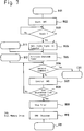
main processor 15. The operation of themain processor 15 is implemented by a program stored in a memory (not shown in the figures). - Referring to Fig. 6, when the
power 100 is turned on, themain processor 15 and the other circuits are initialized (step A01). After the initialization, themain processor 100 sends the shutdown signal to the shutdown circuit 17. - When the initialization is completed, the
main processor 15 determines whether or not effective data is stored in the datablock storage area 23 by checking the contents of the flag area 21 (step A02). - When effective data is not stored, the program branches to step B01 to prepare starting of the
disk memory drive 12. When effective data is stored, the input-output processor 11 sends to the computer 2 a ready signal indicating that the disk memory apparatus 1 is in an accessible state (step A03). - The
main processor 15 waits for a command from the computer 2 (step A04). Upon receiving the command from thecomputer 2, it is determined whether or not the corresponding command is a request for reproducing (step A05). When the command is not a request for reproducing, the program branches to step E01. - When the command is a request for reproducing, the program determines whether or not the requested data blocks are stored in the
non-volatile memory 16 by referring to the data block table area 22 (steps A06 and A07). - When the requested data blocks are not in the
non-volatile memory 16, the program branches to step D01 to read the requested data blocks out of thedisk memory drive 12. - When the requested data blocks are in the
non-volatile memory 16, errors in the data blocks are checked by CRC (step A08). When an error is detected, the program stops to transfer the data blocks in thenon-volatile memory 16 and branches to step D01 to read the data block out of thedisk memory drive 12. - When an error is not detected, the
main processor 15 transfers the corresponding data block to thecomputer 2 from thenon-volatile memory 16 through the input-output processor 11 (step A09). This means that the requested data block can be transferred to thecomputer 2 even before thedisk memory drive 12 is ready for data reproduction. - After transferring the data block, the program executes an access statistics process (step A10).
- Next is described the process of the program on and after step B01.
- Referring to Fig. 7, the
main processor 15 turns off the shutdown signal to start the disk memory drive 12 (step B02). Thereafter, themain processor 15 waits for a signal from thedisk memory drive 12 indicating that thedisk memory drive 12 is ready to reproduce data. - Upon receiving the signal through the disk memory
drive control circuit 13, the program sends the ready signal to the computer 2 (step B04) to inform thecomputer 2 that thedisk memory drive 12 is ready to reproduce data. Thereafter, the shutdown timer T is activated to start counting (step B06). When receiving a command from thecomputer 2 through the input-output processor 11, the program branches to step C01. - When no command is sent from the
computer 2, themain processor 15 controls the operation of thedisk memory drive 12 such as the rotation of the spindle motor and the position of the head (step B07). - When the shutdown timer T informs that the predetermined period of time has lapsed, the
main processor 15 outputs the shutdown signal to the shutdown circuit 17. Upon receiving the shutdown signal, the shutdown circuit 17 turns off the power supplied to thedisk memory drive 12. When the power is turned off, the disk memory drive'control circuit 13 performs preparatory operations such as the positioning of the head or the like (steps B08, B09 and B10). This condition of the disk memory apparatus 1 is hereinafter referred to as a "power saving state". When thedisk memory apparatus 12 is brought into the power saving state, the program branches to step A04 in Fig. 6 (step A11). - As stated above, when
disk memory drive 12 is not accessed for the predetermined time, the power supply ofdisk memory drive 12 is turned off to save power. - Next is described the process of the program on and after step C01.
- Referring to Fig. 8, the program determines whether or not the command sent from the
computer 2 is a data reproduction request (step C02). When the command is not a data reproduction request, the program branches to step C08. - When the command is a data reproduction request, the program determines whether or not the data blocks requested by the
computer 2 are stored in thenon-volatile memory 16 by referring to the data block table area 22 (steps C03 and C04). When the requested data blocks are not in thenon-volatile memory 16, the program branches to step C09. In step C09, the program suspends the counting of the shutdown timer T and branches to step D08. - When the requested data blocks are in the
non-volatile memory 16, errors in the data blocks are checked by CRC (step C05). When an error is detected, the program branches to step C09 to read the data block out of the disk memory. - When an error is not detected, the program transfers the corresponding data block to the
computer 2 from thenon-volatile memory 16 through the input-output processor 11 (step C06). - After the data transfer in step C06, the program executes an access statistics process, which is described below (step C07). After the access statistics process, the program branches to step B12.
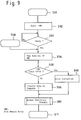
- Next is described the operation of the program after step D01 shown in Fig. 6.
- Referring to Fig. 9, the program turns off the shutdown signal to put the
disk memory drive 12 in motion and waits until receiving a signal from thedisk memory drive 12 indicating that it is ready for data reproduction (steps D02 and D03). Upon receiving this ready signal, the program transfers the requested data blocks in,disk memory drive 12 to the buffer memory 14 (step D04). If a data error is detected by an error inspection function of thebuffer memory 14, a specified error process is executed and thereafter a process shown on and after step D07, as described below, is executed (steps D05 and D09). - When an error is not detected, then the data stored in the
buffer memory 14 is transferred to thecomputer 2 through the input-output processor 11 (step D06). Thereafter, the program executes the access statistical process (step D07) and branches to step B11 to execute steps after step B04 in Fig. 7. - Next is described the operation of the program after step E01.
- Referring to Fig. 10, the program terminates the shutdown signal to put the
disk memory drive 12 in motion and waits until receiving a signal from thedisk memory drive 12 indicating that it is ready for data reproduction (steps E02 and E03). Upon receiving this signal, the program executes the operation instructed by the command from the computer 2 (step E04). Thereafter, the program branches to step B11 in Fig. 7. - Next is described the details of the access statistics process of steps A10, C07 and D07.
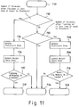
- Referring to Fig. 11, in step F02, the program determines the number of accesses requested after the power is turned on. If the number is less than or equal to a predetermined threshold, the program branches to step F03. If the number exceeds the threshold, the program branches to step F05. The threshold, which is a positive integer, is set considering the capacity of the
non-volatile memory 16, the property of thecomputer 2 and so on. This determination limits the number of accesses that are taken into account when the program updates the contents of thenon-volatile memory 16. - Referring to Figs. 4 and 11, in step F05, the present access is registered in the
entry area 411. Specifically, the first and last block addresses of the present access are stored in the first and lastblock address areas entry areas 411 to 417 is moved to theentry areas 412 to 148, respectively. The data previously stored in theentry area 418 is deleted. - Referring to Figs. 5 and 11, in step F06, the
weight table area 5 is updated. - At first, the weights of data blocks registered in the
area 41 are calculated. In this exemplary embodiment having eightentry areas 411 to 418, (9 - N)² is the weight of the data block which is accessed N times before and registered in the entry area 41N. This weight can be generalized as (M + 1 - N)² where the system has M entry areas. If the same data block is stored in thearea 41, the weight is added up. That is, if a specific data block is registered in theentry areas 413, 415 and 416, the weight of this data block is (9 - 3)² + (9 - 5)² + (9 - 6)² = 61. - After calculating the weight, the data blocks are registered in the
ranking areas 51 to 5n in the descending order of the weight thereof. That is, in the first and last datablock address areas - Next, in step F07, the program determines whether or not the contents of the
non-volatile memory 16 need to be updated. The detailed process of the determination is described below. - In a first step, the program determines the number Sg of the segment area for storing the data blocks frequently accessed soon after the
power 100 is turned on. In this exemplary embodiment, the number Sg is equal to 2 because thesegment areas - In a second step, the program determines the data blocks registered in the
ranking areas 
- In a third step, comparing the first and last data block addresses in the data block table area 22 (Fig. 3) to those in the weight table area 5 (Fig. 5), the program determines whether or not the
segment areas - Next are described the processes after step F03.
- Referring to Fig. 11, when the program determines that the number of accesses after the
power 100 is turned on exceeds the threshold, the program branches to step F03. - In step F03, the program determines whether or not the number of accesses after the shutdown of the
disk memory drive 12 exceeds a predetermined threshold. In step F02, the threshold is set taking into account the capacity of thenon-volatile memory 16, the properties and characteristics of thecomputer 2 and so on. If the number of accesses exceeds the threshold, the program branches to step F03 and the access statistics process is terminated. If the number is less than or equal to the threshold, the program branches to step F08. - In steps F08 to F10, the program executes substantially the same operations as those of steps F05 to F07, respectively, with respect to the
areas 421 to 428 and 233 to 235 instead of theareas 411 to 418 and 231 to 232. - In step F10, the program branches to step G10 when the
non-volatile memory 16 must be updated. - Next is described the processes after steps G01 and G10.
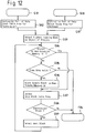
- Referring to Fig. 12, in step G02, the contents of the data
block table area 22 is saved in the memory storing the program and not shown in the figure. After copying, the program initializes theindex areas segment areas power 100 is turned on. - In step G03, the program selects the data block registered in the ranking area 51 (hereinafter referred to as a "first data block", which has highest ranking) as the object of the operation of steps G04 to G09.
- In step G04, referring to the contents of the data
block table area 22 saved in the memory, the program determines whether or not the first data block is stored in thesegment area - In step G05, the program determines whether or not the
non-volatile memory 16 has a free area large enough to store the first data block. The "free area" includes both the area storing no data and the area storing the data blocks not registered in theweight table area 5. If the free area is not found, the program branches to step F04. Otherwise, the program branches to step G06. - In step G06, the contents of the first data block is copied to the free area in the
non-volatile memory 16. The first data block is transferred from thebuffer memory 14. If thebuffer memory 14 does not store the first data block, the first data block is transferred from thedisk memory drive 12. - In step G07, information about the first data block is stored in one of the
index areas 31 to 35 corresponding to the segment area storing the first data block. Specifically, the address in thenon-volatile memory 16 is stored in thesegment address area 311. The first and last data block addresses in the disk memory are stored in the first and lastblock address areas - In step G08, the program determines whether or not all the data blocks registered in the
weight table area 5 are processed by the steps G04 to G07. If all of the data blocks are processed, the program branches to step F04. Otherwise the program proceeds to step G09. In this exemplary operation, the program branches to step G09 because the data blocks registered in theranking areas 52 to 5n are not processed. - In step G09, the program updates the object of the processes of steps G04 to G08. Specifically, the next lower ranking data block is selected as the object. In this exemplary operation, the program selects the data block registered in the
index area 32, which has the second highest ranking. In the similar manner, the data blocks registered in theweight table area 5 are processed according steps G04 to G08 in sequence. - Next is described the operation after step G10.
- Referring to Fig. 12, in step G11, the contents of the data
block table area 22 is saved in the memory storing the program and not shown in figure 12. After copying, the program initializes theindex areas 33 to 35, which correspond to thesegment areas 233 to 235 storing data accessed after the shutdown of thedisk memory drive 12. - In steps G03 to G09, the program executes the steps G03 to G08 with respect to the
segment areas 233 to 235 instead of thesegment areas - Next is described the technical advantages of the present invention.
- First, according to the present invention, a disk memory apparatus can send requested data before the disk memory becomes ready to be accessed because the data is transferred from the non-volatile memory that stores data frequently accessed when the power is turned on.
- Second, the hit-ratio of the data in the
non-volatile memory 16 is high because the data to be stored in thenon-volatile memory 16 is selected according to the statistics of the accesses instead of a conventional replacing strategy such as LRU. - Third, the present invention contributes to power saving and enhances the lifetime of the apparatus because the
disk memory drive 12 is stopped after it is idle for a predetermined period of time. This advantage is enhanced by the high hit-ratio of thenon-volatile memory 16 due to the access statistics. - Next is described the modifications of the present invention.
- The
non-volatile memory 16 may store the positions of "bad spots" in which read errors occurred in addition to the data stated above for effective use ofnon-volatile memory 16. - The areas provided in the
non-volatile memory 16 is not limited to those described above. - The
non-volatile memory 16 may comprise a plurality of memory units. - The nonvolatile memory may store information indicating a status or configuration of said disk memory apparatus because, in many computer systems, the
computer 2 frequently requests this information soon after the disk memory apparatus is turned on. - The present embodiments are therefore, to be considered in all respects as illustrative and not restrictive, the scope of the invention being indicated by the appended claims rather than by the foregoing description and all changes which come within the meanings and range of equivalency of the claims are therefore intended to the embraced therein.
Claims (17)
- A disk memory apparatus coupled with an information processing device and supplied with electrical power, comprising:
a disk memory drive including data therein;
a nonvolatile memory for storing a portion of data contained in said disk memory drive and maintaining contents thereof when said electrical power is removed; and
a controller transferring data in said nonvolatile memory to said information processing device when said disk memory drive is in a condition other than being ready for data reproduction. - A disk memory apparatus according to claim 1, wherein said controller transfers said data when said disk memory device is in a condition other than being ready for data reproduction after turning on of said electrical power.
- A disk memory apparatus according to claim 1 or 2, wherein said nonvolatile memory stores data requested by said information processing device when said electrical power is turned on.
- A disk memory apparatus according to any of claims 1 to 3, wherein said nonvolatile memory stores information indicating a status of said disk memory apparatus.
- A disk memory apparatus according to any of claims 1 to 4, wherein said nonvolatile memory stores information indicating a configuration of said disk memory apparatus.
- A disk memory apparatus according to any of claims 1 to 5, further comprising shutdown means for stopping said disk memory drive after said disk memory apparatus is idle for a predetermined period of time.
- A disk memory apparatus according to claim 6, wherein said controller transfers said data when said disk memory drive is in said condition due to stoppage thereof by said shutdown means.
- A disk memory apparatus according to any of claims 1 to 7, wherein said controller selects data to be stored in said nonvolatile memory according to statistics on data accessed by said information processing device.
- A disk memory apparatus according to claim 8, wherein said controller stores in said nonvolatile memory history information indicating a history of data accessed by said information processing device, and said controller selects data to be stored in said nonvolatile memory according to said history information.
- A disk memory apparatus according to claim 8 or 9, wherein said controller selects data to be stored in said nonvolatile memory according to a frequency of access to said data.
- A disk memory apparatus according to claim 9 or 10, wherein said controller updates said history information according to a predetermined number of data accesses is occurring after power-on of said disk memory apparatus.
- A disk memory apparatus according to any of claims 9 to 11, wherein said controller updates said history information according to a predetermined number of data accesses occurring after stoppage of said disk memory drive by said shutdown means.
- A disk memory apparatus according to any of claims 1 to 12, wherein said controller sends a ready signal to said information processing device when said disk memory drive is in said condition after power-on of said disk memory apparatus.
- A disk memory apparatus according to any of claims 1 to 13, wherein said nonvolatile memory comprises a flash memory.
- A disk memory apparatus according to any of claims 1 to 14, wherein said nonvolatile memory comprises an access memory having a battery back-up.
- A disk memory apparatus according to any of claims 1 to 15, wherein said controller transfers said data prior to said disk memory drive reaching a predetermined rotational speed.
- A disk memory apparatus according to any of claims 1 to 16, wherein said controller transfers said data within a predetermined amount of time after said disk memory apparatus is powered-on.
Applications Claiming Priority (2)
| Application Number | Priority Date | Filing Date | Title |
|---|---|---|---|
| JP6219170A JPH0883148A (en) | 1994-09-13 | 1994-09-13 | Magnetic disk device |
| JP219170/94 | 1994-09-13 |
Publications (1)
| Publication Number | Publication Date |
|---|---|
| EP0702305A1 true EP0702305A1 (en) | 1996-03-20 |
Family
ID=16731302
Family Applications (1)
| Application Number | Title | Priority Date | Filing Date |
|---|---|---|---|
| EP95114329A Withdrawn EP0702305A1 (en) | 1994-09-13 | 1995-09-12 | Disk memory apparatus |
Country Status (2)
| Country | Link |
|---|---|
| EP (1) | EP0702305A1 (en) |
| JP (1) | JPH0883148A (en) |
Cited By (30)
| Publication number | Priority date | Publication date | Assignee | Title |
|---|---|---|---|---|
| WO1997050035A1 (en) * | 1996-06-21 | 1997-12-31 | Memory Corporation Plc | Memory device |
| EP1028425A2 (en) * | 1999-02-12 | 2000-08-16 | Compaq Computer Corporation | Low power system and method for playing compressed audio data |
| WO2002001364A2 (en) * | 2000-06-23 | 2002-01-03 | Intel Corporation | Non-volatile cache integrated with mass storage device |
| WO2003034230A1 (en) | 2001-10-16 | 2003-04-24 | Intel Corporation | Mass storage caching processes for power reduction |
| EP1326245A1 (en) * | 2000-07-28 | 2003-07-09 | Hitachi, Ltd. | Digital information recording and reproducing device |
| US6725342B1 (en) | 2000-09-26 | 2004-04-20 | Intel Corporation | Non-volatile mass storage cache coherency apparatus |
| US6785767B2 (en) | 2000-12-26 | 2004-08-31 | Intel Corporation | Hybrid mass storage system and method with two different types of storage medium |
| US6920533B2 (en) | 2001-06-27 | 2005-07-19 | Intel Corporation | System boot time reduction method |
| WO2005081093A1 (en) * | 2004-02-04 | 2005-09-01 | Sandisk Corporation | Dual media storage device |
| EP1605453A2 (en) * | 2004-06-10 | 2005-12-14 | Marvell World Trade Ltd. | Adaptive storage system |
| EP1612656A2 (en) * | 2004-07-01 | 2006-01-04 | e-Storage Networks, Inc. | Data transmission device having the shape of a standard 3.5" disk |
| US7103724B2 (en) | 2002-04-01 | 2006-09-05 | Intel Corporation | Method and apparatus to generate cache data |
| US7127549B2 (en) | 2004-02-04 | 2006-10-24 | Sandisk Corporation | Disk acceleration using first and second storage devices |
| FR2888032A1 (en) * | 2005-06-30 | 2007-01-05 | Gemplus Sa | METHOD FOR MANAGING NON-VOLATILE MEMORY IN A CHIP CARD |
| US7275135B2 (en) | 2001-08-31 | 2007-09-25 | Intel Corporation | Hardware updated metadata for non-volatile mass storage cache |
| WO2008103359A1 (en) * | 2007-02-20 | 2008-08-28 | Marvell World Trade Ltd. | Externally removable non-volatile semiconductor memory module for hard disk drives |
| US7617359B2 (en) | 2004-06-10 | 2009-11-10 | Marvell World Trade Ltd. | Adaptive storage system including hard disk drive with flash interface |
| US7634585B2 (en) | 2005-11-04 | 2009-12-15 | Sandisk Corporation | In-line cache using nonvolatile memory between host and disk device |
| US7636809B2 (en) | 2004-06-10 | 2009-12-22 | Marvell World Trade Ltd. | Adaptive storage system including hard disk drive with flash interface |
| US7747837B2 (en) | 2005-12-21 | 2010-06-29 | Sandisk Corporation | Method and system for accessing non-volatile storage devices |
| US7769978B2 (en) | 2005-12-21 | 2010-08-03 | Sandisk Corporation | Method and system for accessing non-volatile storage devices |
| US7788514B2 (en) | 2004-06-10 | 2010-08-31 | Marvell World Trade Ltd. | Low power computer with main and auxiliary processors |
| US7788427B1 (en) | 2005-05-05 | 2010-08-31 | Marvell International Ltd. | Flash memory interface for disk drive |
| US7793068B2 (en) | 2005-12-21 | 2010-09-07 | Sandisk Corporation | Dual mode access for non-volatile storage devices |
| US8171219B2 (en) | 2009-03-31 | 2012-05-01 | Intel Corporation | Method and system to perform caching based on file-level heuristics |
| CN101261594B (en) * | 2007-03-08 | 2012-05-30 | 三星电子株式会社 | Method of converting a hybrid hard disk drive to a normal hdd |
| US8386701B2 (en) | 2008-06-30 | 2013-02-26 | Intel Corporation | Apparatus and method for multi-level cache utilization |
| US9104315B2 (en) | 2005-02-04 | 2015-08-11 | Sandisk Technologies Inc. | Systems and methods for a mass data storage system having a file-based interface to a host and a non-file-based interface to secondary storage |
| US9158355B2 (en) | 2006-08-10 | 2015-10-13 | Marvell World Trade Ltd. | Dynamic core switching |
| CN109388339A (en) * | 2017-08-11 | 2019-02-26 | 三星电子株式会社 | Memory Controller and its operating method |
Families Citing this family (1)
| Publication number | Priority date | Publication date | Assignee | Title |
|---|---|---|---|---|
| KR100675010B1 (en) | 2006-02-03 | 2007-01-29 | 삼성전자주식회사 | Method for cache controlling of hybrid hard disk drive, recording medium and apparatus therefor |
Citations (8)
| Publication number | Priority date | Publication date | Assignee | Title |
|---|---|---|---|---|
| EP0357464A2 (en) * | 1988-09-02 | 1990-03-07 | Matsushita Electric Industrial Co., Ltd. | Information recording and reproducing apparatus using optical discs |
| EP0392895A2 (en) * | 1989-04-13 | 1990-10-17 | Sundisk Corporation | Flash EEprom system |
| EP0452989A2 (en) * | 1985-05-29 | 1991-10-23 | Kabushiki Kaisha Toshiba | Magnetic disk controller incorporating a cache system adopting an LRU system |
| EP0475639A2 (en) * | 1990-08-31 | 1992-03-18 | Kawasaki Steel Corporation | Hard disk emulator |
| EP0481716A2 (en) * | 1990-10-15 | 1992-04-22 | Fujitsu Limited | Control system for controlling cache storage unit |
| JPH04205852A (en) * | 1990-11-30 | 1992-07-28 | Hitachi Ltd | Disk cache device |
| WO1992015933A1 (en) * | 1991-03-05 | 1992-09-17 | Zitel Corporation | Cache memory system and method of operating the cache memory system |
| EP0666539A2 (en) * | 1994-02-03 | 1995-08-09 | International Business Machines Corporation | Cache control system |
Family Cites Families (2)
| Publication number | Priority date | Publication date | Assignee | Title |
|---|---|---|---|---|
| JPH04221458A (en) * | 1990-12-25 | 1992-08-11 | Tokyo Electric Co Ltd | Magnetic disk controller |
| JPH05119923A (en) * | 1991-10-29 | 1993-05-18 | Nec Corp | Disk controller |
-
1994
- 1994-09-13 JP JP6219170A patent/JPH0883148A/en active Pending
-
1995
- 1995-09-12 EP EP95114329A patent/EP0702305A1/en not_active Withdrawn
Patent Citations (8)
| Publication number | Priority date | Publication date | Assignee | Title |
|---|---|---|---|---|
| EP0452989A2 (en) * | 1985-05-29 | 1991-10-23 | Kabushiki Kaisha Toshiba | Magnetic disk controller incorporating a cache system adopting an LRU system |
| EP0357464A2 (en) * | 1988-09-02 | 1990-03-07 | Matsushita Electric Industrial Co., Ltd. | Information recording and reproducing apparatus using optical discs |
| EP0392895A2 (en) * | 1989-04-13 | 1990-10-17 | Sundisk Corporation | Flash EEprom system |
| EP0475639A2 (en) * | 1990-08-31 | 1992-03-18 | Kawasaki Steel Corporation | Hard disk emulator |
| EP0481716A2 (en) * | 1990-10-15 | 1992-04-22 | Fujitsu Limited | Control system for controlling cache storage unit |
| JPH04205852A (en) * | 1990-11-30 | 1992-07-28 | Hitachi Ltd | Disk cache device |
| WO1992015933A1 (en) * | 1991-03-05 | 1992-09-17 | Zitel Corporation | Cache memory system and method of operating the cache memory system |
| EP0666539A2 (en) * | 1994-02-03 | 1995-08-09 | International Business Machines Corporation | Cache control system |
Non-Patent Citations (1)
| Title |
|---|
| PATENT ABSTRACTS OF JAPAN vol. 016, no. 551 (P - 1453) 20 November 1992 (1992-11-20) * |
Cited By (61)
| Publication number | Priority date | Publication date | Assignee | Title |
|---|---|---|---|---|
| WO1997050035A1 (en) * | 1996-06-21 | 1997-12-31 | Memory Corporation Plc | Memory device |
| EP1028425A2 (en) * | 1999-02-12 | 2000-08-16 | Compaq Computer Corporation | Low power system and method for playing compressed audio data |
| EP1028425A3 (en) * | 1999-02-12 | 2001-01-03 | Compaq Computer Corporation | Low power system and method for playing compressed audio data |
| WO2002001364A2 (en) * | 2000-06-23 | 2002-01-03 | Intel Corporation | Non-volatile cache integrated with mass storage device |
| WO2002001364A3 (en) * | 2000-06-23 | 2002-04-04 | Intel Corp | Non-volatile cache integrated with mass storage device |
| GB2380031A (en) * | 2000-06-23 | 2003-03-26 | Intel Corp | Non-volatile cache integrated with mass storage device |
| GB2380031B (en) * | 2000-06-23 | 2004-09-29 | Intel Corp | Non-volatile cache integrated with mass storage device |
| EP1326245A4 (en) * | 2000-07-28 | 2006-10-11 | Hitachi Ltd | Digital information recording and reproducing device |
| EP1326245A1 (en) * | 2000-07-28 | 2003-07-09 | Hitachi, Ltd. | Digital information recording and reproducing device |
| US6941423B2 (en) | 2000-09-26 | 2005-09-06 | Intel Corporation | Non-volatile mass storage cache coherency apparatus |
| US6725342B1 (en) | 2000-09-26 | 2004-04-20 | Intel Corporation | Non-volatile mass storage cache coherency apparatus |
| US6785767B2 (en) | 2000-12-26 | 2004-08-31 | Intel Corporation | Hybrid mass storage system and method with two different types of storage medium |
| US7308531B2 (en) | 2000-12-26 | 2007-12-11 | Intel Corporation | Hybrid mass storage system and method |
| US6920533B2 (en) | 2001-06-27 | 2005-07-19 | Intel Corporation | System boot time reduction method |
| US7275135B2 (en) | 2001-08-31 | 2007-09-25 | Intel Corporation | Hardware updated metadata for non-volatile mass storage cache |
| WO2003034230A1 (en) | 2001-10-16 | 2003-04-24 | Intel Corporation | Mass storage caching processes for power reduction |
| CN1312590C (en) * | 2001-10-16 | 2007-04-25 | 英特尔公司 | Mass storage caching processes for power reduction |
| US7103724B2 (en) | 2002-04-01 | 2006-09-05 | Intel Corporation | Method and apparatus to generate cache data |
| US7310699B2 (en) | 2004-02-04 | 2007-12-18 | Sandisk Corporation | Mass storage accelerator |
| EP2254022A1 (en) * | 2004-02-04 | 2010-11-24 | SanDisk Corporation | Dual media storage device |
| US7302534B2 (en) | 2004-02-04 | 2007-11-27 | Sandisk Corporation | Dual media storage device |
| WO2005081093A1 (en) * | 2004-02-04 | 2005-09-01 | Sandisk Corporation | Dual media storage device |
| US7127549B2 (en) | 2004-02-04 | 2006-10-24 | Sandisk Corporation | Disk acceleration using first and second storage devices |
| US7136973B2 (en) | 2004-02-04 | 2006-11-14 | Sandisk Corporation | Dual media storage device |
| EP1605456A2 (en) * | 2004-06-10 | 2005-12-14 | Marvell World Trade Ltd. | Hard disk drive power reduction module |
| US8874948B2 (en) | 2004-06-10 | 2014-10-28 | Marvell World Trade Ltd. | Apparatuses for operating, during respective power modes, transistors of multiple processors at corresponding duty cycles |
| US8572416B2 (en) | 2004-06-10 | 2013-10-29 | Marvell World Trade Ltd. | Low power computer with main and auxiliary processors |
| EP1605453A2 (en) * | 2004-06-10 | 2005-12-14 | Marvell World Trade Ltd. | Adaptive storage system |
| EP1605456A3 (en) * | 2004-06-10 | 2006-10-04 | Marvell World Trade Ltd. | Hard disk drive power reduction module |
| EP1605453A3 (en) * | 2004-06-10 | 2006-10-04 | Marvell World Trade Ltd. | Adaptive storage system |
| US7788514B2 (en) | 2004-06-10 | 2010-08-31 | Marvell World Trade Ltd. | Low power computer with main and auxiliary processors |
| US7702848B2 (en) | 2004-06-10 | 2010-04-20 | Marvell World Trade Ltd. | Adaptive storage system including hard disk drive with flash interface |
| CN100418039C (en) * | 2004-06-10 | 2008-09-10 | 马维尔国际贸易有限公司 | Hard disk drive power reducing module |
| US7512734B2 (en) | 2004-06-10 | 2009-03-31 | Marvell International Ltd. | Adaptive storage system |
| US7617359B2 (en) | 2004-06-10 | 2009-11-10 | Marvell World Trade Ltd. | Adaptive storage system including hard disk drive with flash interface |
| US7636809B2 (en) | 2004-06-10 | 2009-12-22 | Marvell World Trade Ltd. | Adaptive storage system including hard disk drive with flash interface |
| US7634615B2 (en) | 2004-06-10 | 2009-12-15 | Marvell World Trade Ltd. | Adaptive storage system |
| EP1612656A2 (en) * | 2004-07-01 | 2006-01-04 | e-Storage Networks, Inc. | Data transmission device having the shape of a standard 3.5" disk |
| EP1612656A3 (en) * | 2004-07-01 | 2007-04-04 | e-Storage Networks, Inc. | Data transmission device having the shape of a standard 3.5" disk |
| US10126959B2 (en) | 2005-02-04 | 2018-11-13 | Sandisk Technologies Llc | Systems and methods for a mass data storage system having a file-based interface to a host and a non-file-based interface to secondary storage |
| US10055147B2 (en) | 2005-02-04 | 2018-08-21 | Sandisk Technologies Llc | Systems and methods for a mass data storage system having a file-based interface to a host and a non-file-based interface to secondary storage |
| US9104315B2 (en) | 2005-02-04 | 2015-08-11 | Sandisk Technologies Inc. | Systems and methods for a mass data storage system having a file-based interface to a host and a non-file-based interface to secondary storage |
| US7788427B1 (en) | 2005-05-05 | 2010-08-31 | Marvell International Ltd. | Flash memory interface for disk drive |
| US7979614B1 (en) | 2005-05-05 | 2011-07-12 | Marvell International Ltd. | Flash memory/disk drive interface and method for same |
| WO2007003493A1 (en) * | 2005-06-30 | 2007-01-11 | Gemplus | Method for managing a non-volatile memory in a smart card |
| FR2888032A1 (en) * | 2005-06-30 | 2007-01-05 | Gemplus Sa | METHOD FOR MANAGING NON-VOLATILE MEMORY IN A CHIP CARD |
| US7773433B2 (en) | 2005-06-30 | 2010-08-10 | Gemalto Sa | Method for managing a non-volatile memory in a smart card |
| US7634585B2 (en) | 2005-11-04 | 2009-12-15 | Sandisk Corporation | In-line cache using nonvolatile memory between host and disk device |
| US7747837B2 (en) | 2005-12-21 | 2010-06-29 | Sandisk Corporation | Method and system for accessing non-volatile storage devices |
| US8209516B2 (en) | 2005-12-21 | 2012-06-26 | Sandisk Technologies Inc. | Method and system for dual mode access for storage devices |
| US7769978B2 (en) | 2005-12-21 | 2010-08-03 | Sandisk Corporation | Method and system for accessing non-volatile storage devices |
| US7793068B2 (en) | 2005-12-21 | 2010-09-07 | Sandisk Corporation | Dual mode access for non-volatile storage devices |
| US9158355B2 (en) | 2006-08-10 | 2015-10-13 | Marvell World Trade Ltd. | Dynamic core switching |
| WO2008103359A1 (en) * | 2007-02-20 | 2008-08-28 | Marvell World Trade Ltd. | Externally removable non-volatile semiconductor memory module for hard disk drives |
| CN101261594B (en) * | 2007-03-08 | 2012-05-30 | 三星电子株式会社 | Method of converting a hybrid hard disk drive to a normal hdd |
| US8386701B2 (en) | 2008-06-30 | 2013-02-26 | Intel Corporation | Apparatus and method for multi-level cache utilization |
| DE112009000431B4 (en) | 2008-06-30 | 2023-03-23 | Intel Corporation | PROCESSOR-BASED SYSTEM, NON-VOLATILE CACHE AND METHOD OF UTILIZING A NON-VOLATILE CACHE |
| US8171219B2 (en) | 2009-03-31 | 2012-05-01 | Intel Corporation | Method and system to perform caching based on file-level heuristics |
| DE102010013389B4 (en) | 2009-03-31 | 2022-11-24 | Intel Corporation | Method and system for performing caching based on file-level heuristics |
| CN109388339A (en) * | 2017-08-11 | 2019-02-26 | 三星电子株式会社 | Memory Controller and its operating method |
| CN109388339B (en) * | 2017-08-11 | 2023-12-12 | 三星电子株式会社 | Memory controller and method of operating the same |
Also Published As
| Publication number | Publication date |
|---|---|
| JPH0883148A (en) | 1996-03-26 |
Similar Documents
| Publication | Publication Date | Title |
|---|---|---|
| EP0702305A1 (en) | Disk memory apparatus | |
| US5535399A (en) | Solid state disk drive unit having on-board backup non-volatile memory | |
| JP3544610B2 (en) | Memory device | |
| US5802551A (en) | Method and apparatus for controlling the writing and erasing of information in a memory device | |
| US7111134B2 (en) | Subsystem and subsystem processing method | |
| US7020756B2 (en) | Data saving method and external storage device | |
| US5935259A (en) | System and method for preventing damage to media files within a digital camera device | |
| US7418436B2 (en) | Information processing apparatus, memory management apparatus, memory management method, and information processing method | |
| JP4268396B2 (en) | Non-volatile memory device file management that can be programmed once | |
| EP0834882B1 (en) | Memory management method and apparatus | |
| US5778443A (en) | Method and apparatus for conserving power and system resources in a computer system employing a virtual memory | |
| US5732408A (en) | Control system for controlling the pending data to write back in a cache storage unit | |
| US6092160A (en) | Memory management method | |
| EP0666539A2 (en) | Cache control system | |
| JPH0291749A (en) | Nonvolatile type semiconductor memory device | |
| US5727232A (en) | Disk system having buffer with designated area to be used for repeat access data | |
| KR100390228B1 (en) | Information storage device and information storage method | |
| EP0667579A1 (en) | Cache for optical storage device | |
| US7805572B2 (en) | Cache pollution avoidance | |
| JPH0535614A (en) | Back-up device | |
| JPH064228A (en) | Semiconductor disk device | |
| JPH09319667A (en) | Hybernation processing method | |
| JPS62130440A (en) | Cache subsystem | |
| JP3125634B2 (en) | Electronic computer system | |
| JPH1050084A (en) | Memory controller and memory access method |
Legal Events
| Date | Code | Title | Description |
|---|---|---|---|
| PUAI | Public reference made under article 153(3) epc to a published international application that has entered the european phase |
Free format text: ORIGINAL CODE: 0009012 |
|
| 17P | Request for examination filed |
Effective date: 19960104 |
|
| AK | Designated contracting states |
Kind code of ref document: A1 Designated state(s): DE FR GB |
|
| 17Q | First examination report despatched |
Effective date: 19990929 |
|
| STAA | Information on the status of an ep patent application or granted ep patent |
Free format text: STATUS: THE APPLICATION IS DEEMED TO BE WITHDRAWN |
|
| 18D | Application deemed to be withdrawn |
Effective date: 20000210 |