EP0702321A1 - Method and apparatus for classifying picture elements in radiation images - Google Patents
Method and apparatus for classifying picture elements in radiation images Download PDFInfo
- Publication number
- EP0702321A1 EP0702321A1 EP95116196A EP95116196A EP0702321A1 EP 0702321 A1 EP0702321 A1 EP 0702321A1 EP 95116196 A EP95116196 A EP 95116196A EP 95116196 A EP95116196 A EP 95116196A EP 0702321 A1 EP0702321 A1 EP 0702321A1
- Authority
- EP
- European Patent Office
- Prior art keywords
- picture elements
- image
- mean
- predetermined
- classifying
- Prior art date
- Legal status (The legal status is an assumption and is not a legal conclusion. Google has not performed a legal analysis and makes no representation as to the accuracy of the status listed.)
- Granted
Links
Images


Classifications
-
- G—PHYSICS
- G06—COMPUTING; CALCULATING OR COUNTING
- G06T—IMAGE DATA PROCESSING OR GENERATION, IN GENERAL
- G06T7/00—Image analysis
- G06T7/0002—Inspection of images, e.g. flaw detection
- G06T7/0012—Biomedical image inspection
-
- G—PHYSICS
- G06—COMPUTING; CALCULATING OR COUNTING
- G06T—IMAGE DATA PROCESSING OR GENERATION, IN GENERAL
- G06T7/00—Image analysis
-
- G—PHYSICS
- G06—COMPUTING; CALCULATING OR COUNTING
- G06T—IMAGE DATA PROCESSING OR GENERATION, IN GENERAL
- G06T7/00—Image analysis
- G06T7/10—Segmentation; Edge detection
- G06T7/12—Edge-based segmentation
-
- G—PHYSICS
- G06—COMPUTING; CALCULATING OR COUNTING
- G06V—IMAGE OR VIDEO RECOGNITION OR UNDERSTANDING
- G06V10/00—Arrangements for image or video recognition or understanding
- G06V10/40—Extraction of image or video features
- G06V10/44—Local feature extraction by analysis of parts of the pattern, e.g. by detecting edges, contours, loops, corners, strokes or intersections; Connectivity analysis, e.g. of connected components
-
- G—PHYSICS
- G06—COMPUTING; CALCULATING OR COUNTING
- G06T—IMAGE DATA PROCESSING OR GENERATION, IN GENERAL
- G06T2207/00—Indexing scheme for image analysis or image enhancement
- G06T2207/10—Image acquisition modality
- G06T2207/10116—X-ray image
-
- G—PHYSICS
- G06—COMPUTING; CALCULATING OR COUNTING
- G06T—IMAGE DATA PROCESSING OR GENERATION, IN GENERAL
- G06T2207/00—Indexing scheme for image analysis or image enhancement
- G06T2207/30—Subject of image; Context of image processing
- G06T2207/30004—Biomedical image processing
- G06T2207/30061—Lung
-
- G—PHYSICS
- G06—COMPUTING; CALCULATING OR COUNTING
- G06T—IMAGE DATA PROCESSING OR GENERATION, IN GENERAL
- G06T2207/00—Indexing scheme for image analysis or image enhancement
- G06T2207/30—Subject of image; Context of image processing
- G06T2207/30004—Biomedical image processing
- G06T2207/30096—Tumor; Lesion
Definitions
- This invention relates to a method for classifying picture elements in a radiation image into those belonging to a certain image pattern and those not belonging to a certain image pattern and an apparatus for carrying out the method.
- This invention particularly relates to a method and apparatus for classifying picture elements such that, from an image signal representing a radiation image of an object, a judgment can be made as to whether a predetermined picture element P0 in the radiation image falls or does not fall within the region corresponding to a predetermined pattern in the radiation image.
- phosphors when certain kinds of phosphors are exposed to radiation such as X-rays, ⁇ -rays, ⁇ -rays, ⁇ -rays, cathode rays or ultraviolet rays, they store part of the energy of the radiation. Then, when the phosphor which has been exposed to the radiation is exposed to stimulating rays such as visible light, light is emitted by the phosphor in proportion to the amount of energy stored thereon during its exposure to the radiation. A phosphor exhibiting such properties is referred to as a stimulable phosphor. As disclosed in U.S. Patent Nos. 4,258,264, 4,276,473, 4,315,318, 4,387,428, and Japanese Unexamined Patent Publication No.
- a sheet provided with a layer of the stimulable phosphor (hereinafter referred to as a stimulable phosphor sheet) is first exposed to radiation which has passed through an object such as the human body in order to store a radiation image of the object thereon, and is then scanned with stimulating rays, such as a laser beam, which cause it to emit light in proportion to the amount of energy stored during exposure to the radiation.
- stimulating rays such as a laser beam
- the light emitted by the stimulable phosphor sheet upon stimulation thereof, is photoelectrically detected and converted into an electric image signal.
- the image signal is then used to reproduce the radiation image of the object as a visible image on a recording material such as photographic film, on a display device such as a cathode ray tube (CRT), or the like.
- CTR cathode ray tube
- Radiation image recording and reproducing systems which use stimulable phosphor sheets are advantageous over conventional radiography using silver halide photographic materials, in that images can be recorded even when the energy intensity of the radiation to which the stimulable phosphor sheet is exposed varies over a wide range. More specifically, since the amount of light which the stimulable phosphor sheet emits when being stimulated varies over a wide range and is proportional to the amount of energy stored thereon during its exposure to the radiation, it is possible to obtain an image having a desirable density regardless of the energy intensity of the radiation to which the stimulable phosphor sheet was exposed.
- an appropriate read-out gain is set when the emitted light is being detected and converted into an electric signal to be used in the reproduction of a visible image on a recording material, such as photographic film, or on a display device, such as a CRT.
- an image pattern can be detected in a complicated radiation image by processing the image signal representing it in various ways.
- the image signal is made up of a series of image signal components, and with appropriate processing the image signal components corresponding to a particular image pattern can be found. For example, from a very complicated radiation image, such as an X-ray image of the chest of a human body, which includes various linear and circular patterns, an approximately circular image corresponding to a tumor, or the like, can be detected.
- a pattern for example, a tumor image
- a complicated radiation image such as an X-ray image of the chest of a human body
- a visible image is reproduced and displayed such that the detected pattern can be viewed clearly.
- a visible image can serve as an effective tool in, particularly, the efficient and accurate diagnosis of an illness.
- U.S. Patent No. 4,769,850 discloses a method for finding a circular pattern, wherein an image signal representing an X-ray image of the chest of a human body, or the like, is processed with a spatial-domain filter composed of three concentric circles.
- the primary object of the present invention is to provide a method and apparatus for determining whether a picture element is in a circular pattern even if several circular patterns having different sizes are present in a radiation image and even if the shapes of the circular patterns deviate slightly from circles, with the judgment being made accurately as to whether a predetermined picture element P0 in the radiation image falls or does not fall within the region corresponding to a particular circular pattern in the radiation image.
- Another object of the present invention is to provide a method and apparatus for classifying picture elements as belonging to or not belonging to a circular pattern wherein an accurate judgment is made as to whether a predetermined picture element P0 in a radiation image falls or does not fall within the region corresponding to a circular pattern in the radiation image, with the judgement being based on the shape of the circular pattern, instead of being based on the level of contrast of the circular pattern with the surrounding image areas.
- a further object of the present invention is to provide a method and apparatus for classifying picture elements wherein a circular pattern and a linear pattern, which may be present in a radiation image, can be accurately discriminated from each other with a single filter, and a judgment can be made accurately as to whether a predetermined picture element P0 in the radiation image falls or does not fall within the region corresponding to a circular pattern in the radiation image.
- a still further object of the present invention is to provide a method and apparatus for classifying picture elements wherein the adverse effects from noise in a radiation image are eliminated, and the contour of a predetermined pattern in the radiation image, which pattern is to be found, can be detected accurately.
- the present invention provides a method for classifying picture elements as belonging to or not belonging to a pattern wherein, from an image signal made up of a series of image signal components representing a radiation image of an object, judgments are made as to whether predetermined picture elements in the radiation image fall or do not fall within the region corresponding to a predetermined pattern in the radiation image, the method for classifying picture elements comprising the steps of:
- the present invention further provides an apparatus for classifying picture elements as belonging to or not belonging to a pattern wherein, from an image signal made up of a series of image signal components representing a radiation image of an object, judgments are made as to whether predetermined picture elements in the radiation image fall or do not fall within the region corresponding to a predetermined pattern in the radiation image, the apparatus for classifying picture elements comprising:
- mean-level value means one of various types of values which represent the mean level of the values of the image signal components representing a plurality of picture elements located in each region.
- the mean-level value may be the arithmetical mean, the geometric mean, or the median value of the values of the image signal components representing a plurality of picture elements located in each region.
- the mean-level value may be calculated with the formula expressed as (maximum value + minimum value)/2 .
- the areas of the peripheral regions are set such that peripheral regions which are more remote from the predetermined picture element P0 will have larger areas. This does not mean that all of the peripheral regions which are located at equal distances from the predetermined picture element P0 will have equal areas.
- the relationship between the distances and the areas of the peripheral regions may vary in respective directions. Also, in each direction, the areas of adjacent peripheral regions need not necessarily be different from each other.
- the areas of peripheral regions may vary step-wise such that a group of peripheral regions located close to the predetermined picture element P0 will all have small areas, a group of peripheral regions located further from the predetermined picture element P0 will all have somewhat larger areas, and a group of peripheral regions located even further from the predetermined picture element P0 will all have relatively large areas.
- the method and apparatus for classifying picture elements in accordance with the present invention embrace various such embodiments within their scopes.
- the value of j i.e. the number of peripheral regions located along each of the lines Li, may vary for the respective lines Li so that a picture element belonging to, for example, an elliptic pattern can be so classified.
- characteristic value Ci means, for example, the maximum value of the differences between the mean-level values (Q0, Qij) corresponding to adjacent regions located along each of the lines Li, or the maximum value of the differences between the mean-level value Q0 corresponding to the center region and the mean-level values Qij corresponding to the peripheral regions located along each of the lines Li.
- the characteristic value Ci may be the maximum value of weighted differences between the mean-level values (Q0, Qij) corresponding to adjacent regions located along each of the lines Li, or the maximum value of weighted differences between the mean-level value Q0 corresponding to the center region and the mean-level values Qij corresponding to the peripheral regions located along each of the lines Li.
- the characteristic value Ci may be the value given by the formula (maximum value of the aforesaid differences)-(predetermined value), the mean value of the aforesaid differences, or the like.
- an image signal representing a radiation image includes much noise due to the sway in the radiation during the recording of the radiation image, or the like. If the areas of the aforesaid regions are small, errors in the judgment as to whether a predetermined picture element P0 falls or does not fall within the region corresponding to a predetermined pattern will occur due to the adverse effects of the noise. Also, the contour of the predetermined pattern, which is to be found, cannot be detected accurately. In order for the adverse effects of the noise to be eliminated, regions having large areas may be employed. However, if the areas of the regions are large, the location of the predetermined pattern cannot be detected accurately, and the contour of the predetermined pattern, which is to be found, cannot be detected accurately.
- the method and apparatus for classifying picture elements in accordance with the present invention solves the problems described above. Specifically, with the method and apparatus for classifying picture elements in accordance with the present invention, regions having small areas are used close to the predetermined picture element P0. Therefore, an accurate judgment can be made as to whether a predetermined picture element P0 falls or does not fall within the region corresponding to the predetermined pattern. However, as described above, in cases where regions having small areas are employed, the judgment is adversely affected by noise. With the method and apparatus for classifying picture elements in accordance with the present invention, in order for this problem to be eliminated, regions remote from the predetermined picture element P0 are assigned large areas.
- the filter employed in the method and apparatus for classifying picture elements in accordance with the present invention the judgment as to whether a predetermined picture element P0 falls or does not fall within the region corresponding to a predetermined pattern is made from the mean-level values of the image signal components corresponding to regions having appropriate, comparatively large areas. Accordingly, the adverse effects of noise can be sufficiently prevented from affecting the judgment about a picture element.
- an X-ray image is stored on a stimulable phosphor sheet, and an image of a tumor, which typically has an approximately spherical shape in the lungs of a human body, is detected from the X-ray image.
- the tumor image In a visible image reproduced from the X-ray image, the tumor image has a lower density than the areas of the image surrounding the tumor image.
- Figure 2 is a schematic view showing an example of an X-ray image recording apparatus.
- X-rays 12 are produced by an X-ray source 11 of an X-ray image recording apparatus and irradiated to the chest 13a of a human body 13.
- X-rays 12a which have passed through the human body 13, impinge upon a stimulable phosphor sheet 14. In this manner, an X-ray image of the chest 13a of a human body 13 is stored on the stimulable phosphor sheet 14.
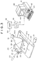
- Figure 3 is a perspective view showing an example of an X-ray image read-out apparatus and a computer system which is provided with the embodiment of the apparatus for classifying picture elements in accordance with the present invention.
- a stimulable phosphor sheet 14, on which an X-ray image has been stored, is placed at a predetermined position in an X-ray image read-out apparatus 20.
- the stimulable phosphor sheet 14 is then conveyed in a sub-scanning direction indicated by the arrow Y by a sheet conveyance means 22, which is constituted of an endless belt or the like and which is operated by a motor 21.
- a laser beam 24, which serves as stimulating rays, is produced by a laser beam source 23, and is reflected and deflected by a rotating polygon mirror 26 which is quickly rotated by a motor 25 in the direction indicated by the arrow.
- the laser beam 24 then passes through a converging lens 27 constituted of an f ⁇ lens or the like.
- the direction of the optical path of the laser beam 24 is then changed by a mirror 28, and the laser beam 24 impinges upon the stimulable phosphor sheet 14 and scans it in a main scanning direction indicated by the arrow X, which direction is approximately normal to the sub-scanning direction indicated by the arrow Y.
- the exposed portion of the stimulable phosphor sheet 14 emits light 29 in an amount proportional to the amount of energy stored thereon during its exposure to the X-rays.
- the emitted light 29 is guided by a light guide member 30 and photoelectrically detected by a photomultiplier 31.
- the light guide member 30 is made from a light guiding material such as an acrylic plate and has a linear light input face 30a, positioned so that it extends along the main scanning line on the stimulable phosphor sheet 14, and a ring-shaped light output face 30b, positioned so that it is in close contact with a light receiving face of the photomultiplier 31.
- the emitted light 29, which has entered the light guide member 30 at its light input face 30a, is guided through repeated total reflection inside of the light guide member 30, emanates from the light output face 30b, and is received by the photomultiplier 31. In this manner, the amount of the emitted light 29, which amount represents the X-ray image, is converted into an electric signal by the photomultiplier 31.
- An analog output signal S0 generated by the photomultiplier 31 is logarithmically amplified by a logarithmic amplifier 32, and digitized by an A/D converter 33 into an electric image signal S1.
- the image signal S1 is then fed into a computer system 40.
- the computer system 40 is provided with an embodiment of the first apparatus for classifying picture elements as belonging to or not belonging to a circular pattern in accordance with the present invention.
- the computer system 70 comprises a main body 41 in which a CPU and an internal memory are incorporated, a disk drive unit 42 which operates a floppy disk serving as a subsidiary memory, a keyboard 43 from which necessary instructions, or the like, are fed into the computer system 40, and a CRT display device 44 which displays necessary information.
- the image signal S1 which is made up of a series of image signal components representing the X-ray image and which has been fed into the computer system 40, a judgment is made as to whether a predetermined picture element P0 in the X-ray image falls or does not fall within the region corresponding to a tumor image (circular pattern) in the X-ray image.
- a predetermined picture element P0 in the X-ray image falls or does not fall within the region corresponding to a tumor image (circular pattern) in the X-ray image.
- Each of the picture elements in an X-ray image may be assigned as the predetermined picture element P0, and the judgment operation may be repeated for the image signal components representing each of the picture elements of the X-ray image. In this manner, the tumor image in the X-ray image can be detected.
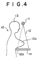
- Figure 4 is a schematic view showing an example of an X-ray image recording apparatus.
- X-rays 12 are produced by an X-ray source 11 of an X-ray image recording apparatus and irradiated to the mamma 13a of a human body 13.
- X-rays 12a which have passed through the human body 13, impinge upon a stimulable phosphor sheet 14. In this manner, an X-ray image of the mamma 13a is stored on the stimulable phosphor sheet 14.
- the X-ray image is read out in the same manner as that described above from the stimulable phosphor sheet 14 in the X-ray image read-out apparatus shown in Figure 3.
- the image signal S1 obtained from the image read-out operation is fed into the computer system 40.
- the image signal S1 which is made up of a series of image signal components representing the X-ray image and which has been fed into the computer system 40, a judgment is made as to whether a predetermined picture element P0 in the X-ray image falls or does not fall within the region corresponding to a tumor image in the X-ray image.
- Each picture element in the X-ray image may be assigned as the predetermined picture element P0, and the judgment operation may be repeated for each image signal component representing each picture element in the X-ray image. In this manner, the tumor image is detected in the X-ray image.
- Figure 5 is a diagram having a predetermined picture element P0 from an X-ray image in the middle, which diagram serves as an aid in explaining how a spatial-domain filter works, the spatial-domain filter being employed to detect a circular tumor image in the embodiments of the method and apparatus for classifying picture elements as belonging to or not belonging to a pattern in accordance with the present invention.
- a judgment is made as to whether a predetermined picture element P0 in the X-ray image falls or does not fall within the region corresponding to the tumor image in the X-ray image.
- the tumor image in the X-ray image can be detected by processing the image signal components representing the picture elements in the X-ray image with the filter illustrated in Figure 5.
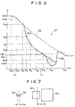
- Figure 6 is a graph showing an example of the profile of the X-ray image around a predetermined picture element P0 in the direction (x direction) along which the lines L1 and L5 shown in Figure 5 extend.
- the predetermined picture element P0 is located in a tumor image 57, which is present in the region of the X-ray image at which the image density (the value of the image signal representing the X-ray image) changes sharply.
- the predetermined picture element P0 is present in the vicinity of a boundary line 57b of the tumor image 57.
- the profile of a tumor image i.e. the distribution of the values of image signal components representing the tumor image
- the profile of the tumor image 57 will often not be symmetric bilaterally. It is important that the tumor image 57 can be detected even in such cases.
- a plurality of (in this case, eight) imaginary lines Li extend from the predetermined picture element P0 in the X-ray image to the peripheral parts of the X-ray image.
- the area of a center region Q0 including the predetermined picture element P0 is selected.
- Each of the peripheral regions Qij includes one of a plurality of picture elements Pij, which are located at the intersections of each of the lines Li and the circles Rj.
- P11, P12, P13, P14, and P15 denote the picture elements located at the intersections of a line L1 and circles R1, R2, R3, R4, and R5.
- P51, P52, P53, P54, and P55 denote the picture elements located at the intersections of a line L5 and the circles R1, R2, R3, R4, and R5.
- Q11, Q12, Q13, Q14, Q15, Q51, Q52, Q53, Q54, and Q55 denote the peripheral regions which respectively include the picture elements P11, P12, P13, P14, P15, P51, P52, P53, P54, and P55.) As illustrated in Figure 5, the peripheral regions Qij which are more remote from the predetermined picture element P0 (i.e. the peripheral regions Qij having a larger value of j) are assigned larger areas.
- Q0 represents both the center region and the mean-level value of the values of image signal components representing the picture elements, which are located in the center region.
- the differences ⁇ ij between the mean-level values corresponding to adjacent peripheral regions are calculated from the formulas For each of the lines Li, the maximum value Ci of the differences ⁇ ij is then found.
- the maximum value Ci thus found is employed as the characteristic value Ci.
- ⁇ 14 Q14-Q13 ⁇ d , where d denotes a predetermined threshold value, and ⁇ 14 is thus very small.
- d denotes a predetermined threshold value
- ⁇ 14 is thus very small.
- the maximum value of ⁇ 11, ⁇ 12, and ⁇ 13 is assigned as the characteristic value C1. Even when ⁇ 11, ⁇ 12, and ⁇ 13 are less than ⁇ 15, ⁇ 15 is ignored.
- ⁇ 51 Q51 - Q0
- ⁇ 52 Q52 - Q51
- ⁇ 53 Q53 - Q52
- ⁇ 54 Q54 - Q53
- ⁇ 55 Q55 - Q54
- ⁇ 51 is greater than ⁇ 52, ⁇ 53, ⁇ 54, and ⁇ 55. (Though Q54 and Q55 are not shown in Figure 11, assume that ⁇ 54 and ⁇ 55 are small.) Therefore, ⁇ 51 is found to be the maximum value C5.
- the differences ⁇ ij between the mean-level values corresponding to adjacent peripheral regions are calculated from Formula (20).
- the differences ⁇ ij' between the mean-level value Q0 corresponding to the center region and the mean-level values Qij corresponding to the peripheral regions are used, the effects of the sharp change in the image density in said region are superposed upon the change in the image density due to the tumor image 57.
- the amount of information about the change in the image density due to the tumor image 57 is reduced, and the accuracy with which the tumor image 57 is detected becomes low.
- the differences between the mean-level values corresponding to adjacent peripheral regions are calculated from Formula (20)
- the effects of the sharp change in the image density in the region in which the tumor image 57 is present can be minimized, and the accuracy with which the tumor image 57 is detected (i.e. the accuracy with which the judgment is made as to whether a predetermined picture element P0 falls or does not fall in the region corresponding to the tumor image 57) becomes high.
- Each of the mean-level values Q14 and Q15, from which the maximum value C1 is calculated with Formula (25), represents the mean level of the values of the image signal components corresponding to the picture elements located in peripheral regions having a large area. Therefore, the judgment as to whether a predetermined picture element P0 falls or does not fall within the region corresponding to the tumor image 57 can be made without being adversely affected by noise, which is generally included in the image signal representing the X-ray image.
- the position of the boundary line 57a of the tumor image 57 only vague information can be obtained. Specifically, it can be detected only that the boundary line 57a is present somewhere between the two peripheral regions Q14 and Q15 both of which have large areas.
- the predetermined picture element P0 is present in the vicinity of the boundary line 57b and is remote from the boundary line 57a. Therefore, as for the position of the boundary line 57a, it is sufficient to determine that it is present. Accordingly, peripheral regions having as large an area as possible should preferably be employed, provided that the presence of the boundary line 57a can be detected.
- Each of the mean-level values Q0 and Q51, from which the maximum value C5 is calculated with Formula (26), represents the mean level of the values of the image signal components corresponding to the picture elements located in a region having a small area. Therefore, the position of the boundary line 57b can be detected accurately. In such cases, because the mean-level values corresponding to regions having small areas are used, adverse effects occur from noise. However, with the whole filter employed in the embodiments of the method and apparatus for classifying picture elements in accordance with the present invention, mean-level values corresponding to peripheral regions having large areas, like the peripheral regions Q14 and Q15, are also used. Accordingly, the adverse effects from noise can be sufficiently suppressed.
- Figure 7 is an explanatory view showing the relationship between the areas of regions used during calculations and the accuracy with which the position of a boundary line of a tumor image can be detected.
- the position of the boundary line 57a is detected from the mean-level values corresponding to the two peripheral regions Q14 and Q15, which have large areas. Therefore, it cannot be detected accurately at which position in the width dl shown in Figure 7 the boundary line 57a is present.
- the position of the boundary line 57b is detected from the mean-level values corresponding to the two regions Q0 and Q51, which have small areas. Therefore, the position of the boundary line 57b can be detected with a high accuracy because it falls somewhere within the width d2 shown in Figure 7.
- the maximum values Ci are found for the plurality of the lines Li, calculations are made to find the mean-level value, for example, the mean value, of two maximum values, which have been found for each set of two lines extending from the predetermined picture element P0 in opposite directions.
- mean values M15, M26, M37, and M48 are calculated respectively for the set of lines L1 and L5, the set of lines L2 and L6, the set of lines L3 and L7, and the set of lines L4 and L8.
- two lines extending from the predetermined picture element P0 in opposite directions are grouped into a single set. Therefore, a tumor image can be detected accurately even when, as shown in Figure 6, the tumor image 57 is present in a region in which the background image density changes sharply and the distribution of the values of the image signal components representing the tumor image 57 is asymmetric.
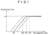
- the horizontal axis represents the mean values M15, M26, M37, and M48, which have been calculated in the manner described above.
- the vertical axis represents rating values C15, C26, C37, and C48, which correspond respectively to the mean values M15, M26, M37, and M48.
- a rating value of zero is assigned to the mean values M15, M26, M37, and M48 in cases where they are smaller than a certain value M1.
- a rating value of 1.0 is assigned to the mean values M15, M26, M37, and M48 in cases where they are larger than a certain value M2.
- a rating value falling within the range of 0.0 to 1.0 is assigned to the mean values M15, M26, M37, and M48, depending upon their values. In this manner, the rating values C15, C26, C37, and C48 are found, which correspond respectively to the mean values M15, M26, M37, and M48.
- the sum of the rating values C15, C26, C37, and C48, which is expressed as C C15 + C26 + C37 + C48 is taken as the characteristic value C.
- the characteristic value C will fall within the range of a minimum value 0.0 to a maximum value 4.0.
- the characteristic value C is then compared with a predetermined threshold value Th. From whether C ⁇ Th or C ⁇ Th, the judgment is made as to whether the predetermined picture element P0 falls or does not fall within the region corresponding to the tumor image.
- the characteristic value C calculated from Formula (32) will take a larger value in cases where the shape of the tumor image is closer to a circle.
- the rating values C15, C26, C37, and C48 are calculated from an equation such as the one represented by the double-dot chained line in Figure 3, wherein saturation occurs at a large value, e.g. M2'', the characteristic value C calculated from Formula (32) will take a larger value in cases where the contrast of the tumor image with respect to the surrounding image regions is higher. Therefore, an appropriate equation for transforming the mean values into rating values can be selected in accordance with the characteristics of the tumor image which is to be found.
- the process of making the judgment from the mean values M15, M26, M37, and M48 is not limited to using the characteristic value C and may be carried out in various other manners.
- the mean values M15, M26, M37, and M48 may be compared with a threshold value Th'. In cases where all of the mean values M15, M26, M37, and M48 are larger than the threshold value Th', it may be judged that the predetermined picture element P0 falls within the region corresponding to the tumor image. Alternatively, in cases where at least three of the mean values M15, M26, M37, and M48 are larger than the threshold value Th', it may be judged that the predetermined picture element P0 falls within the region corresponding to the tumor image.
- a tumor image is detected which appears, typically, as a circular pattern on the X-ray image.
- the method and apparatus for classifying picture elements in accordance with the present invention are not limited to the detection of a tumor image nor to the processing of an X-ray image of a chest.
- the method and apparatus for classifying picture elements in accordance with the present invention is also applicable when an image of a calcified part is to be detected from an image of a mamma.
- the method and apparatus for classifying picture elements in accordance with the present invention are not limited to the detection of circular patterns.
- a linear pattern such as a rib image or a blood vessel image, can be detected.
- the method and apparatus for classifying picture elements as belonging to or not belonging to a pattern in accordance with the present invention is also applicable when a recording medium other than a stimulable phosphor sheet, for example, X-ray film, is used.
- the mean-level values Qij are used, each of which represents the mean level of the values of image signal components representing a plurality of picture elements located in each of the peripheral regions Qij.
- Each of the peripheral regions Qij includes one of a plurality of picture elements Pij, which are located on each of eight lines, L1 through L8.
- the number of lines Li is not limited to eight, but may, for example, be 16.
- the distances from the predetermined picture element P0 are not limited to the five distances (r1, r2, r3, r4, and r5).
- the method and apparatus for classifying picture elements in accordance with the present invention are applicable widely when, from an image signal representing a radiation image of an object, a judgment is made as to whether a predetermined picture element P0 in the radiation image falls or does not fall within the region corresponding to a predetermined pattern in the radiation image.
- the image signal representing a radiation image need not necessarily be processed with the filter described above.
- an operator may manually designate a predetermined point in the radiation image and may judge whether the predetermined point falls or does not fall in the region corresponding to a predetermined pattern.
Abstract
Description
- This invention relates to a method for classifying picture elements in a radiation image into those belonging to a certain image pattern and those not belonging to a certain image pattern and an apparatus for carrying out the method. This invention particularly relates to a method and apparatus for classifying picture elements such that, from an image signal representing a radiation image of an object, a judgment can be made as to whether a predetermined picture element P0 in the radiation image falls or does not fall within the region corresponding to a predetermined pattern in the radiation image.
- Techniques for reading out a recorded radiation image in order to obtain an image signal, carrying out appropriate image processing on the image signal, and then reproducing a visible image by use of the processed image signal have heretofore been known in various fields. For example, as disclosed in Japanese Patent Publication No. 61(1986)-5193, an X-ray image is recorded on an X-ray film having a small gamma value chosen according to the type of image processing to be carried out, the X-ray image is read out from the X-ray film and converted into an electric signal (image signal), and the image signal is processed and then used for reproducing the X-ray image as a visible image on a copy photograph or the like. In this manner, a visible image having good image quality with high contrast, high sharpness, high graininess, or the like can be reproduced.
- Also, when certain kinds of phosphors are exposed to radiation such as X-rays, α-rays, β-rays, γ-rays, cathode rays or ultraviolet rays, they store part of the energy of the radiation. Then, when the phosphor which has been exposed to the radiation is exposed to stimulating rays such as visible light, light is emitted by the phosphor in proportion to the amount of energy stored thereon during its exposure to the radiation. A phosphor exhibiting such properties is referred to as a stimulable phosphor. As disclosed in U.S. Patent Nos. 4,258,264, 4,276,473, 4,315,318, 4,387,428, and Japanese Unexamined Patent Publication No. 56(1981)-11395, it has been proposed to use stimulable phosphors in radiation image recording and reproducing systems. Specifically, a sheet provided with a layer of the stimulable phosphor (hereinafter referred to as a stimulable phosphor sheet) is first exposed to radiation which has passed through an object such as the human body in order to store a radiation image of the object thereon, and is then scanned with stimulating rays, such as a laser beam, which cause it to emit light in proportion to the amount of energy stored during exposure to the radiation. The light emitted by the stimulable phosphor sheet, upon stimulation thereof, is photoelectrically detected and converted into an electric image signal. The image signal is then used to reproduce the radiation image of the object as a visible image on a recording material such as photographic film, on a display device such as a cathode ray tube (CRT), or the like.
- Radiation image recording and reproducing systems which use stimulable phosphor sheets are advantageous over conventional radiography using silver halide photographic materials, in that images can be recorded even when the energy intensity of the radiation to which the stimulable phosphor sheet is exposed varies over a wide range. More specifically, since the amount of light which the stimulable phosphor sheet emits when being stimulated varies over a wide range and is proportional to the amount of energy stored thereon during its exposure to the radiation, it is possible to obtain an image having a desirable density regardless of the energy intensity of the radiation to which the stimulable phosphor sheet was exposed. In order to obtain the desired image density, an appropriate read-out gain is set when the emitted light is being detected and converted into an electric signal to be used in the reproduction of a visible image on a recording material, such as photographic film, or on a display device, such as a CRT.
- Recently, in the radiation image recording and reproducing systems which use X-ray film or stimulable phosphor sheets, particularly in such radiation image recording and reproducing systems designed to facilitate medical diagnoses, not only have image signals been produced in ways which ensure that the visible images produced from them will be of high quality, but image signals have also been processed in ways which allow certain image patterns to be extracted from radiation images. One type of processing which results in the extraction of an image pattern is disclosed in, for example, U.S. Patent No. 4,769,850.
- Specifically, an image pattern can be detected in a complicated radiation image by processing the image signal representing it in various ways. The image signal is made up of a series of image signal components, and with appropriate processing the image signal components corresponding to a particular image pattern can be found. For example, from a very complicated radiation image, such as an X-ray image of the chest of a human body, which includes various linear and circular patterns, an approximately circular image corresponding to a tumor, or the like, can be detected.
- After a pattern, for example, a tumor image, is detected in a complicated radiation image, such as an X-ray image of the chest of a human body, a visible image is reproduced and displayed such that the detected pattern can be viewed clearly. Such a visible image can serve as an effective tool in, particularly, the efficient and accurate diagnosis of an illness.
- U.S. Patent No. 4,769,850 discloses a method for finding a circular pattern, wherein an image signal representing an X-ray image of the chest of a human body, or the like, is processed with a spatial-domain filter composed of three concentric circles.
- However, radiation images of human bodies have very complicated configurations. For example, the sizes of tumor images in X-ray images of chests are multifarious. Also, the shapes of some tumor images are not circular, but may be, for example, approximately elliptic. With the method for finding a circular pattern, wherein a spatial-domain filter composed of three concentric circles is utilized, tumor images cannot be detected accurately in cases where several tumor images having different sizes are present together or in cases where the shape of a tumor image is not circular. After an image pattern is detected and a visible image showing the detected image pattern is reproduced in, for example, a radiation image recording and reproducing system designed to facilitate medical diagnoses, a physician will base his diagnosis primarily on how the detected pattern looks. If a certain pattern (a certain tumor image) is not detected accurately, a physician may fail to find a tumor. This is a very serious problem.
- The primary object of the present invention is to provide a method and apparatus for determining whether a picture element is in a circular pattern even if several circular patterns having different sizes are present in a radiation image and even if the shapes of the circular patterns deviate slightly from circles, with the judgment being made accurately as to whether a predetermined picture element P0 in the radiation image falls or does not fall within the region corresponding to a particular circular pattern in the radiation image.
- Another object of the present invention is to provide a method and apparatus for classifying picture elements as belonging to or not belonging to a circular pattern wherein an accurate judgment is made as to whether a predetermined picture element P0 in a radiation image falls or does not fall within the region corresponding to a circular pattern in the radiation image, with the judgement being based on the shape of the circular pattern, instead of being based on the level of contrast of the circular pattern with the surrounding image areas.
- A further object of the present invention is to provide a method and apparatus for classifying picture elements wherein a circular pattern and a linear pattern, which may be present in a radiation image, can be accurately discriminated from each other with a single filter, and a judgment can be made accurately as to whether a predetermined picture element P0 in the radiation image falls or does not fall within the region corresponding to a circular pattern in the radiation image.
- A still further object of the present invention is to provide a method and apparatus for classifying picture elements wherein the adverse effects from noise in a radiation image are eliminated, and the contour of a predetermined pattern in the radiation image, which pattern is to be found, can be detected accurately.
- The present invention provides a method for classifying picture elements as belonging to or not belonging to a pattern wherein, from an image signal made up of a series of image signal components representing a radiation image of an object, judgments are made as to whether predetermined picture elements in the radiation image fall or do not fall within the region corresponding to a predetermined pattern in the radiation image,
the method for classifying picture elements comprising the steps of: - i) calculating:
- (a) the value Q0 of an image signal component representing a predetermined picture element P0, or a mean-level value Q0 of the values of image signal components representing a plurality of picture elements, which are located in a center region including said predetermined picture element P0, and
- (b) mean-level values Qij, each representing the mean level of the values of image signal components representing a plurality of picture elements located in each of a plurality of peripheral regions, each said peripheral region including one of a plurality of picture elements Pij, which are located on each of a plurality of lines Li, where i=1, 2, ..., n, extending from said predetermined picture element P0 to the peripheral parts of said radiation image, and which picture elements Pij are spaced a plurality of predetermined distances rij, where j=1, 2, ..., m, from said predetermined picture element P0, the areas of said peripheral regions being selected such that peripheral regions which are more remote from said predetermined picture element P0 have larger areas,
- ii) calculating a characteristic value Ci, which represents the change in said radiation image in the direction along which each of said lines Li extends, for each of said lines Li, and
- iii) from a plurality of the characteristic values Ci, which have been calculated for the plurality of directions along which said lines Li extend, judging whether said predetermined picture element P0 falls or does not fall within the region corresponding to said predetermined pattern.
- The present invention further provides an apparatus for classifying picture elements as belonging to or not belonging to a pattern wherein, from an image signal made up of a series of image signal components representing a radiation image of an object, judgments are made as to whether predetermined picture elements in the radiation image fall or do not fall within the region corresponding to a predetermined pattern in the radiation image,
the apparatus for classifying picture elements comprising: - i) a mean calculating means for calculating:
- (a) the value Q0 of an image signal component representing a predetermined picture element P0, or a mean-level value Q0 of the values of image signal components representing a plurality of picture elements, which are located in a center region including said predetermined picture element P0, and
- (b) mean-level values Qij, each representing the mean level of the values of image signal components representing a plurality of picture elements located in each of a plurality of peripheral regions, each said peripheral region including one of a plurality of picture elements Pij, which are located on each of a plurality of lines Li, where i=1, 2, ..., n, extending from said predetermined picture element P0 to the peripheral parts of said radiation image, and which picture elements Pij are spaced a plurality of predetermined distances rij, where j=1, 2, ..., m, from said predetermined picture element P0, the areas of said peripheral regions being selected such that peripheral regions which are more remote from said predetermined picture element P0 have larger areas,
- ii) a characteristic value calculating means for calculating a characteristic value Ci, which represents the change in said radiation image in the direction along which each of said lines Li extends, for each of said lines Li, and
- iii) a judgment means for judging, from a plurality of the characteristic values Ci, which have been calculated for the plurality of directions along which said lines Li extend, whether said predetermined picture element P0 falls or does not fall within the region corresponding to said predetermined pattern.
- The term "mean-level value" as used herein for the method and apparatus for classifying picture elements in accordance with the present invention means one of various types of values which represent the mean level of the values of the image signal components representing a plurality of picture elements located in each region. For example, the mean-level value may be the arithmetical mean, the geometric mean, or the median value of the values of the image signal components representing a plurality of picture elements located in each region. Alternatively, the mean-level value may be calculated with the formula expressed as

- In the method and apparatus for classifying picture elements in accordance with the present invention, the areas of the peripheral regions are set such that peripheral regions which are more remote from the predetermined picture element P0 will have larger areas. This does not mean that all of the peripheral regions which are located at equal distances from the predetermined picture element P0 will have equal areas. For example, in cases where a filter having a high sensitivity in certain directions is to be implemented, the relationship between the distances and the areas of the peripheral regions may vary in respective directions. Also, in each direction, the areas of adjacent peripheral regions need not necessarily be different from each other. For example, in each direction, the areas of peripheral regions may vary step-wise such that a group of peripheral regions located close to the predetermined picture element P0 will all have small areas, a group of peripheral regions located further from the predetermined picture element P0 will all have somewhat larger areas, and a group of peripheral regions located even further from the predetermined picture element P0 will all have relatively large areas. The method and apparatus for classifying picture elements in accordance with the present invention embrace various such embodiments within their scopes.
- In the method and apparatus for classifying picture elements in accordance with the present invention, the value of j, i.e. the number of peripheral regions located along each of the lines Li, may vary for the respective lines Li so that a picture element belonging to, for example, an elliptic pattern can be so classified.
- The term "characteristic value Ci" as used herein for the method and apparatus for classifying picture elements in accordance with the present invention means, for example, the maximum value of the differences between the mean-level values (Q0, Qij) corresponding to adjacent regions located along each of the lines Li, or the maximum value of the differences between the mean-level value Q0 corresponding to the center region and the mean-level values Qij corresponding to the peripheral regions located along each of the lines Li. Alternatively, the characteristic value Ci may be the maximum value of weighted differences between the mean-level values (Q0, Qij) corresponding to adjacent regions located along each of the lines Li, or the maximum value of weighted differences between the mean-level value Q0 corresponding to the center region and the mean-level values Qij corresponding to the peripheral regions located along each of the lines Li. As another alternative, the characteristic value Ci may be the value given by the formula (maximum value of the aforesaid differences)-(predetermined value), the mean value of the aforesaid differences, or the like.
- In general, an image signal representing a radiation image includes much noise due to the sway in the radiation during the recording of the radiation image, or the like. If the areas of the aforesaid regions are small, errors in the judgment as to whether a predetermined picture element P0 falls or does not fall within the region corresponding to a predetermined pattern will occur due to the adverse effects of the noise. Also, the contour of the predetermined pattern, which is to be found, cannot be detected accurately. In order for the adverse effects of the noise to be eliminated, regions having large areas may be employed. However, if the areas of the regions are large, the location of the predetermined pattern cannot be detected accurately, and the contour of the predetermined pattern, which is to be found, cannot be detected accurately.
- The method and apparatus for classifying picture elements in accordance with the present invention solves the problems described above. Specifically, with the method and apparatus for classifying picture elements in accordance with the present invention, regions having small areas are used close to the predetermined picture element P0. Therefore, an accurate judgment can be made as to whether a predetermined picture element P0 falls or does not fall within the region corresponding to the predetermined pattern. However, as described above, in cases where regions having small areas are employed, the judgment is adversely affected by noise. With the method and apparatus for classifying picture elements in accordance with the present invention, in order for this problem to be eliminated, regions remote from the predetermined picture element P0 are assigned large areas. Therefore, with the filter employed in the method and apparatus for classifying picture elements in accordance with the present invention, the judgment as to whether a predetermined picture element P0 falls or does not fall within the region corresponding to a predetermined pattern is made from the mean-level values of the image signal components corresponding to regions having appropriate, comparatively large areas. Accordingly, the adverse effects of noise can be sufficiently prevented from affecting the judgment about a picture element.
-
- Figure 1 is a graph showing how a characteristic value is determined which is used during a judgment as to whether a predetermined picture element P0 falls or does not fall within the region corresponding to the tumor image,
- Figure 2 is a schematic view showing an example of an X-ray image recording apparatus,
- Figure 3 is a perspective view showing an example of an X-ray image read-out apparatus and a computer system which is provided with the embodiment of the apparatus for classifying picture elements in accordance with the present invention,
- Figure 4 is a schematic view showing an example of an X-ray image recording apparatus,
- Figure 5 is a diagram having a predetermined picture element P0 from an X-ray image in the middle, which diagram serves as an aid in explaining how a spatial-domain filter works, the spatial-domain falter being employed to detect a tumor image in embodiments of the method and apparatus for classifying picture elements in accordance with the present invention,
- Figure 6 is a graph showing an example of the profile of an X-ray image around a predetermined picture element P0 in the direction (x direction) along which the lines L1 and L5 shown in Figure 10 extend, and
- Figure 7 is an explanatory view showing the relationship between the areas of regions used during calculations and the accuracy with which the position of a boundary line of a tumor image can be detected.
- The present invention will hereinbelow be described in further detail with reference to the accompanying drawings.
- Embodiments of the method and apparatus for classifying picture elements as belonging to or not belonging to a pattern in accordance with the present invention will be described below. In the embodiments, an X-ray image is stored on a stimulable phosphor sheet, and an image of a tumor, which typically has an approximately spherical shape in the lungs of a human body, is detected from the X-ray image. In a visible image reproduced from the X-ray image, the tumor image has a lower density than the areas of the image surrounding the tumor image.
- Figure 2 is a schematic view showing an example of an X-ray image recording apparatus.
- With reference to Figure 2,
X-rays 12 are produced by an X-ray source 11 of an X-ray image recording apparatus and irradiated to the chest 13a of ahuman body 13. X-rays 12a, which have passed through thehuman body 13, impinge upon astimulable phosphor sheet 14. In this manner, an X-ray image of the chest 13a of ahuman body 13 is stored on thestimulable phosphor sheet 14. - Figure 3 is a perspective view showing an example of an X-ray image read-out apparatus and a computer system which is provided with the embodiment of the apparatus for classifying picture elements in accordance with the present invention.
- With reference to Figure 3, a
stimulable phosphor sheet 14, on which an X-ray image has been stored, is placed at a predetermined position in an X-ray image read-out apparatus 20. Thestimulable phosphor sheet 14 is then conveyed in a sub-scanning direction indicated by the arrow Y by a sheet conveyance means 22, which is constituted of an endless belt or the like and which is operated by amotor 21. Alaser beam 24, which serves as stimulating rays, is produced by alaser beam source 23, and is reflected and deflected by arotating polygon mirror 26 which is quickly rotated by amotor 25 in the direction indicated by the arrow. Thelaser beam 24 then passes through a converginglens 27 constituted of an fθ lens or the like. The direction of the optical path of thelaser beam 24 is then changed by amirror 28, and thelaser beam 24 impinges upon thestimulable phosphor sheet 14 and scans it in a main scanning direction indicated by the arrow X, which direction is approximately normal to the sub-scanning direction indicated by the arrow Y. When thestimulable phosphor sheet 14 is exposed to thelaser beam 24, the exposed portion of thestimulable phosphor sheet 14 emits light 29 in an amount proportional to the amount of energy stored thereon during its exposure to the X-rays. The emittedlight 29 is guided by alight guide member 30 and photoelectrically detected by aphotomultiplier 31. Thelight guide member 30 is made from a light guiding material such as an acrylic plate and has a linearlight input face 30a, positioned so that it extends along the main scanning line on thestimulable phosphor sheet 14, and a ring-shapedlight output face 30b, positioned so that it is in close contact with a light receiving face of thephotomultiplier 31. The emittedlight 29, which has entered thelight guide member 30 at itslight input face 30a, is guided through repeated total reflection inside of thelight guide member 30, emanates from thelight output face 30b, and is received by thephotomultiplier 31. In this manner, the amount of the emittedlight 29, which amount represents the X-ray image, is converted into an electric signal by thephotomultiplier 31. - An analog output signal S0 generated by the
photomultiplier 31 is logarithmically amplified by alogarithmic amplifier 32, and digitized by an A/D converter 33 into an electric image signal S1. - The image signal S1 is then fed into a
computer system 40. Thecomputer system 40 is provided with an embodiment of the first apparatus for classifying picture elements as belonging to or not belonging to a circular pattern in accordance with the present invention. The computer system 70 comprises amain body 41 in which a CPU and an internal memory are incorporated, adisk drive unit 42 which operates a floppy disk serving as a subsidiary memory, akeyboard 43 from which necessary instructions, or the like, are fed into thecomputer system 40, and aCRT display device 44 which displays necessary information. - From the image signal S1, which is made up of a series of image signal components representing the X-ray image and which has been fed into the
computer system 40, a judgment is made as to whether a predetermined picture element P0 in the X-ray image falls or does not fall within the region corresponding to a tumor image (circular pattern) in the X-ray image. Each of the picture elements in an X-ray image may be assigned as the predetermined picture element P0, and the judgment operation may be repeated for the image signal components representing each of the picture elements of the X-ray image. In this manner, the tumor image in the X-ray image can be detected. - Figure 4 is a schematic view showing an example of an X-ray image recording apparatus.
- With reference to Figure 4,
X-rays 12 are produced by an X-ray source 11 of an X-ray image recording apparatus and irradiated to the mamma 13a of ahuman body 13. X-rays 12a, which have passed through thehuman body 13, impinge upon astimulable phosphor sheet 14. In this manner, an X-ray image of the mamma 13a is stored on thestimulable phosphor sheet 14. - Thereafter, the X-ray image is read out in the same manner as that described above from the
stimulable phosphor sheet 14 in the X-ray image read-out apparatus shown in Figure 3. The image signal S1 obtained from the image read-out operation is fed into thecomputer system 40. - From the image signal S1, which is made up of a series of image signal components representing the X-ray image and which has been fed into the
computer system 40, a judgment is made as to whether a predetermined picture element P0 in the X-ray image falls or does not fall within the region corresponding to a tumor image in the X-ray image. Each picture element in the X-ray image may be assigned as the predetermined picture element P0, and the judgment operation may be repeated for each image signal component representing each picture element in the X-ray image. In this manner, the tumor image is detected in the X-ray image. - In an apparatus for classifying picture elements as belonging to or not belonging to a pattern, which apparatus is incorporated in the
computer system 40 shown in Figure 3, a judgment is made in the manner described below as to whether a predetermined picture element P0 in the X-ray image falls or does not fall within the region corresponding to a tumor image (circular pattern) in the X-ray image. - Figure 5 is a diagram having a predetermined picture element P0 from an X-ray image in the middle, which diagram serves as an aid in explaining how a spatial-domain filter works, the spatial-domain filter being employed to detect a circular tumor image in the embodiments of the method and apparatus for classifying picture elements as belonging to or not belonging to a pattern in accordance with the present invention. A judgment is made as to whether a predetermined picture element P0 in the X-ray image falls or does not fall within the region corresponding to the tumor image in the X-ray image. The tumor image in the X-ray image can be detected by processing the image signal components representing the picture elements in the X-ray image with the filter illustrated in Figure 5.
- Figure 6 is a graph showing an example of the profile of the X-ray image around a predetermined picture element P0 in the direction (x direction) along which the lines L1 and L5 shown in Figure 5 extend. In this example, the predetermined picture element P0 is located in a
tumor image 57, which is present in the region of the X-ray image at which the image density (the value of the image signal representing the X-ray image) changes sharply. The predetermined picture element P0 is present in the vicinity of aboundary line 57b of thetumor image 57. Typically, the profile of a tumor image (i.e. the distribution of the values of image signal components representing the tumor image) is approximately symmetric bilaterally. However, in cases where, for example, thetumor image 57 is present in a region of the X-ray image at which the image density changes sharply as in the example illustrated, the profile of thetumor image 57 will often not be symmetric bilaterally. It is important that thetumor image 57 can be detected even in such cases. - As shown in Figure 5, a plurality of (in this case, eight) imaginary lines Li, where i=1, 2, ..., 8, extend from the predetermined picture element P0 in the X-ray image to the peripheral parts of the X-ray image. Also, five imaginary circles Rj, where j=1, 2, 3, 4, 5, which have radii r1, r2, r3, r4, and r5, extend around the predetermined picture element P0. Thereafter, the area of a center region Q0 including the predetermined picture element P0 is selected. Also, the areas of peripheral regions Qij, where i=1, 2, ..., 8 and j=1, 2, 3, 4, 5, are selected for each of the lines Li. Each of the peripheral regions Qij includes one of a plurality of picture elements Pij, which are located at the intersections of each of the lines Li and the circles Rj. (In Figure 10, P11, P12, P13, P14, and P15 denote the picture elements located at the intersections of a line L1 and circles R1, R2, R3, R4, and R5. Also, P51, P52, P53, P54, and P55 denote the picture elements located at the intersections of a line L5 and the circles R1, R2, R3, R4, and R5. Further, Q11, Q12, Q13, Q14, Q15, Q51, Q52, Q53, Q54, and Q55 denote the peripheral regions which respectively include the picture elements P11, P12, P13, P14, P15, P51, P52, P53, P54, and P55.) As illustrated in Figure 5, the peripheral regions Qij which are more remote from the predetermined picture element P0 (i.e. the peripheral regions Qij having a larger value of j) are assigned larger areas.
- Thereafter, a calculation is made to find a mean-level value Q0 of the values of image signal components representing a plurality of picture elements, which are located in the center region Q0. Also, calculations are made to find mean-level values Qij, where i=1, 2, ..., 8 and j=1, 2, 3, 4, 5, each representing the mean level of the values of image signal components representing a plurality of picture elements located in each of the peripheral regions Qij, where i=1, 2, ..., 8 and j=1, 2, 3, 4, 5. As an aid in facilitating the explanation, Q0 represents both the center region and the mean-level value of the values of image signal components representing the picture elements, which are located in the center region. Also, Qij, where i=1, 2, ..., 8 and j=1, 2, 3, 4, 5, represents both the peripheral regions and the mean-level values representing the mean level of the values of the image signal components representing the picture elements, which are located in each of the peripheral regions.
- Thereafter, from the mean-level value Q0 corresponding to the center region and the mean-level values Qij, where i=1, 2, ..., 8 and j=1, 2, 3, 4, 5, corresponding to the peripheral regions, the differences Δij between the mean-level values corresponding to adjacent peripheral regions are calculated from the formulas

For each of the lines Li, the maximum value Ci of the differences Δij is then found. In the embodiments of this method and apparatus for classifying picture elements in accordance with the present invention, the maximum value Ci thus found is employed as the characteristic value Ci. Specifically, for the line L1, the maximum value C1 is found from the differences expressed as
- However, as for the part of the image pattern indicated by the single-dot chained line in Figure 6,

- For the line L5, the maximum value C5 is found from the differences expressed as

- In the embodiments of the method and apparatus for classifying picture elements in accordance with the present invention, the differences Δij between the mean-level values corresponding to adjacent peripheral regions are calculated from Formula (20). Alternatively, the differences between the mean-level value Q0 corresponding to the center region and the mean-level values Qij corresponding to the peripheral regions may be calculated from the formula

tumor image 57 is present in a region in which the image density changes sharply, when the differences Δij' between the mean-level value Q0 corresponding to the center region and the mean-level values Qij corresponding to the peripheral regions are used, the effects of the sharp change in the image density in said region are superposed upon the change in the image density due to thetumor image 57. Therefore, the amount of information about the change in the image density due to thetumor image 57 is reduced, and the accuracy with which thetumor image 57 is detected becomes low. In the embodiments of the method and apparatus for classifying picture elements in accordance with the present invention, because the differences between the mean-level values corresponding to adjacent peripheral regions are calculated from Formula (20), the effects of the sharp change in the image density in the region in which thetumor image 57 is present can be minimized, and the accuracy with which thetumor image 57 is detected (i.e. the accuracy with which the judgment is made as to whether a predetermined picture element P0 falls or does not fall in the region corresponding to the tumor image 57) becomes high. - Each of the mean-level values Q14 and Q15, from which the maximum value C1 is calculated with Formula (25), represents the mean level of the values of the image signal components corresponding to the picture elements located in peripheral regions having a large area. Therefore, the judgment as to whether a predetermined picture element P0 falls or does not fall within the region corresponding to the
tumor image 57 can be made without being adversely affected by noise, which is generally included in the image signal representing the X-ray image. As for the position of theboundary line 57a of thetumor image 57, only vague information can be obtained. Specifically, it can be detected only that theboundary line 57a is present somewhere between the two peripheral regions Q14 and Q15 both of which have large areas. However, as shown in Figure 6, the predetermined picture element P0 is present in the vicinity of theboundary line 57b and is remote from theboundary line 57a. Therefore, as for the position of theboundary line 57a, it is sufficient to determine that it is present. Accordingly, peripheral regions having as large an area as possible should preferably be employed, provided that the presence of theboundary line 57a can be detected. - Each of the mean-level values Q0 and Q51, from which the maximum value C5 is calculated with Formula (26), represents the mean level of the values of the image signal components corresponding to the picture elements located in a region having a small area. Therefore, the position of the
boundary line 57b can be detected accurately. In such cases, because the mean-level values corresponding to regions having small areas are used, adverse effects occur from noise. However, with the whole filter employed in the embodiments of the method and apparatus for classifying picture elements in accordance with the present invention, mean-level values corresponding to peripheral regions having large areas, like the peripheral regions Q14 and Q15, are also used. Accordingly, the adverse effects from noise can be sufficiently suppressed. - Figure 7 is an explanatory view showing the relationship between the areas of regions used during calculations and the accuracy with which the position of a boundary line of a tumor image can be detected.
- The position of the
boundary line 57a is detected from the mean-level values corresponding to the two peripheral regions Q14 and Q15, which have large areas. Therefore, it cannot be detected accurately at which position in the width dl shown in Figure 7 theboundary line 57a is present. However, the position of theboundary line 57b is detected from the mean-level values corresponding to the two regions Q0 and Q51, which have small areas. Therefore, the position of theboundary line 57b can be detected with a high accuracy because it falls somewhere within the width d2 shown in Figure 7. - After, the maximum values Ci are found for the plurality of the lines Li, calculations are made to find the mean-level value, for example, the mean value, of two maximum values, which have been found for each set of two lines extending from the predetermined picture element P0 in opposite directions. Specifically, mean values M15, M26, M37, and M48 are calculated respectively for the set of lines L1 and L5, the set of lines L2 and L6, the set of lines L3 and L7, and the set of lines L4 and L8. For the set of lines L1 and L5, the mean value M15 is calculated from the formula

tumor image 57 is present in a region in which the background image density changes sharply and the distribution of the values of the image signal components representing thetumor image 57 is asymmetric. - From the mean values M15, M26, M37, and M48, which have been calculated in the manner described above, a judgment is made as to whether a predetermined picture element P0 falls or does not fall within the region corresponding to the tumor image. In the method and apparatus for classifying picture elements as belonging to or not belonging to a pattern in accordance with the present invention, no limitation is imposed on how the judgment is made from the mean values M15, M26, M37, and M48. By way of example, the judgment may be made in the manner described below.
- How a characteristic value C is determined, which is used during the judgment as to whether a predetermined picture element P0 falls or does not fall within the region corresponding to the tumor image, will be described hereinbelow with reference to Figure 1. In Figure 1, the horizontal axis represents the mean values M15, M26, M37, and M48, which have been calculated in the manner described above. The vertical axis represents rating values C15, C26, C37, and C48, which correspond respectively to the mean values M15, M26, M37, and M48.
- A rating value of zero is assigned to the mean values M15, M26, M37, and M48 in cases where they are smaller than a certain value M1. A rating value of 1.0 is assigned to the mean values M15, M26, M37, and M48 in cases where they are larger than a certain value M2. In cases where the mean values M15, M26, M37, and M48 fall within the range of M1 to M2, a rating value falling within the range of 0.0 to 1.0 is assigned to the mean values M15, M26, M37, and M48, depending upon their values. In this manner, the rating values C15, C26, C37, and C48 are found, which correspond respectively to the mean values M15, M26, M37, and M48. The sum of the rating values C15, C26, C37, and C48, which is expressed as

- The characteristic value C is then compared with a predetermined threshold value Th. From whether C≧Th or C<Th, the judgment is made as to whether the predetermined picture element P0 falls or does not fall within the region corresponding to the tumor image.
- In cases where the rating values C15, C26, C37, and C48 are calculated from an equation such as the one, represented by the single-dot chained line in Figure 1, wherein saturation occurs at a small value, e.g. M2', the characteristic value C calculated from Formula (32) will take a larger value in cases where the shape of the tumor image is closer to a circle. In cases where the rating values C15, C26, C37, and C48 are calculated from an equation such as the one represented by the double-dot chained line in Figure 3, wherein saturation occurs at a large value, e.g. M2'', the characteristic value C calculated from Formula (32) will take a larger value in cases where the contrast of the tumor image with respect to the surrounding image regions is higher. Therefore, an appropriate equation for transforming the mean values into rating values can be selected in accordance with the characteristics of the tumor image which is to be found.
- The process of making the judgment from the mean values M15, M26, M37, and M48 is not limited to using the characteristic value C and may be carried out in various other manners. For example, the mean values M15, M26, M37, and M48 may be compared with a threshold value Th'. In cases where all of the mean values M15, M26, M37, and M48 are larger than the threshold value Th', it may be judged that the predetermined picture element P0 falls within the region corresponding to the tumor image. Alternatively, in cases where at least three of the mean values M15, M26, M37, and M48 are larger than the threshold value Th', it may be judged that the predetermined picture element P0 falls within the region corresponding to the tumor image. As another alternative, the sum,

- In the embodiments of the method and apparatus for classifying picture elements in accordance with the present invention, which have been described above with reference to Figures 5, 6, and 7, from an X-ray image of the chest of a human body, which image has been stored on a stimulable phosphor sheet, a tumor image is detected which appears, typically, as a circular pattern on the X-ray image. However, the method and apparatus for classifying picture elements in accordance with the present invention are not limited to the detection of a tumor image nor to the processing of an X-ray image of a chest. For example, the method and apparatus for classifying picture elements in accordance with the present invention is also applicable when an image of a calcified part is to be detected from an image of a mamma. Further, the method and apparatus for classifying picture elements in accordance with the present invention are not limited to the detection of circular patterns. For example, instead of the characteristic value C being calculated with Formula (32), a characteristic value C', which is weighted for a specific direction, may be calculated from the formula

- The method and apparatus for classifying picture elements as belonging to or not belonging to a pattern in accordance with the present invention is also applicable when a recording medium other than a stimulable phosphor sheet, for example, X-ray film, is used.
- In the aforesaid embodiments of the method and apparatus for classifying picture elements in accordance with the present invention, as shown in Figure 5, the mean-level values Qij are used, each of which represents the mean level of the values of image signal components representing a plurality of picture elements located in each of the peripheral regions Qij. Each of the peripheral regions Qij includes one of a plurality of picture elements Pij, which are located on each of eight lines, L1 through L8. However, the number of lines Li is not limited to eight, but may, for example, be 16. Also, the distances from the predetermined picture element P0 are not limited to the five distances (r1, r2, r3, r4, and r5).
- As described above, the method and apparatus for classifying picture elements in accordance with the present invention are applicable widely when, from an image signal representing a radiation image of an object, a judgment is made as to whether a predetermined picture element P0 in the radiation image falls or does not fall within the region corresponding to a predetermined pattern in the radiation image.
- In the method and apparatus for classifying picture elements in accordance with the present invention, the image signal representing a radiation image need not necessarily be processed with the filter described above. For example, an operator may manually designate a predetermined point in the radiation image and may judge whether the predetermined point falls or does not fall in the region corresponding to a predetermined pattern.
Claims (14)
- A method for classifying picture elements as belonging to or not belonging to a pattern wherein, from an image signal made up of a series of image signal components representing a radiation image of an object, judgments are made as to whether predetermined picture elements in the radiation image fall or do not fall within the region corresponding to a predetermined pattern in the radiation image,
the method for classifying picture elements comprising the steps of:i) calculating:(a) the value Q0 of an image signal component representing a predetermined picture element P0, or a mean-level value Q0 of the values of image signal components representing a plurality of picture elements, which are located in a center region including said predetermined picture element P0, and(b) mean-level values Qij, each representing the mean level of the values of image signal components representing a plurality of picture elements located in each of a plurality of peripheral regions, each said peripheral region including one of a plurality of picture elements Pij, which are located on each of a plurality of lines Li, where i=1, 2, ..., n, extending from said predetermined picture element P0 to peripheral parts of said radiation image, and which picture elements Pij are spaced a plurality of predetermined distances rij, where j=1, 2, ..., m, from said predetermined picture element P0, the areas of said peripheral regions being selected such that peripheral regions which are more remote from said predetermined picture element P0 have larger areas,ii) calculating a characteristic value Ci, which represents the change in said radiation image in the direction along which each of said lines Li extends, for each of said lines Li, andiii) from a plurality of the characteristic values Ci, which have been calculated for the plurality of directions along which said lines Li extend, judging whether said predetermined picture element P0 falls or does not fall within the region corresponding to said predetermined pattern. - A method for classifying picture elements as defined in Claim 1 wherein said characteristic value Ci is the maximum value of differences between the mean-level values (Q0, Qij) corresponding to adjacent regions located along each of said lines Li.
- A method for classifying picture elements as defined in Claim 1 wherein said characteristic value Ci is the maximum value of differences between said mean-level value Q0 corresponding to said center region and the respective mean-level values Qij corresponding to the peripheral regions located along each of said lines Li.
- A method for classifying picture elements as defined in Claim 1 wherein said radiation image of the object has been stored on a stimulable phosphor sheet.
- A method for classifying picture elements as defined in Claim 4 wherein said image signal is obtained from a read-out operation wherein said stimulable phosphor sheet is exposed to stimulating rays, which cause said stimulable phosphor sheet to emit light in proportion to the amount of energy stored thereon during its exposure to radiation, and the emitted light is detected photoelectrically.
- A method for classifying picture elements as defined in Claim 5 wherein said stimulating rays are a laser beam.
- A method for classifying picture elements as defined in Claim 1 wherein said radiation image of the object has been recorded on photographic film.
- An apparatus for classifying picture elements as belonging to or not belonging to a pattern wherein, from an image signal made up of a series of image signal components representing a radiation image of an object, judgments are made as to whether predetermined picture elements in the radiation image fall or do not fall within the region corresponding to a predetermined pattern in the radiation image,
the apparatus for classifying picture elements comprising:i) a mean calculating means for calculating:(a) the value Q0 of an image signal component representing a predetermined picture element P0, or a mean-level value Q0 of the values of image signal components representing a plurality of picture elements, which are located in a center region including said predetermined picture element P0, and(b) mean-level values Qij, each representing the mean level of the values of image signal components representing a plurality of picture elements located in each of a plurality of peripheral regions, each said peripheral region including one of a plurality of picture elements Pij, which are located on each of a plurality of lines Li, where i=1, 2, ..., n, extending from said predetermined picture element P0 to the peripheral parts of said radiation image, and which pictures elements Pij are spaced a plurality of predetermined distances rij, where j=1, 2, ..., m, from said predetermined picture element P0, the areas of said peripheral regions being selected such that peripheral regions which are more remote from said predetermined picture element P0 have larger areas,ii) a characteristic value calculating means for calculating a characteristic value Ci, which represents the change in said radiation image in the direction along which each of said lines Li extends, for each of said lines Li, andiii) a judgment means for judging, from a plurality of the characteristic values Ci, which have been calculated for the plurality of directions along which said lines Li extend, whether said predetermined picture element P0 falls or does not fall within the region corresponding to said predetermined pattern. - An apparatus for classifying picture elements as defined in Claim 8 wherein said characteristic value Ci is the maximum value of differences between the mean-level values (Q0, Qij) corresponding to adjacent regions located along each of said lines Li.
- An apparatus for classifying picture elements as defined in Claim 8 wherein said characteristic value Ci is the maximum value of differences between said mean-level value Q0 corresponding to said center region and the respective mean-level values Qij corresponding to the peripheral regions located along each of said lines Li.
- An apparatus for classifying picture elements as defined in Claim 8 wherein said radiation image of the object has been stored on a stimulable phosphor sheet.
- An apparatus for classifying picture elements as defined in Claim 11 wherein said image signal is obtained from a read-out operation wherein said stimulable phosphor sheet is exposed to stimulating rays, which cause said stimulable phosphor sheet to emit light in proportion to the amount of energy stored thereon during its exposure to radiation, and the emitted light is detected photoelectrically.
- An apparatus for classifying picture elements as defined in Claim 12 wherein said stimulating rays are a laser beam.
- An apparatus for classifying picture elements as defined in Claim 8 wherein said radiation image of the object has been recorded on photographic film.
Applications Claiming Priority (13)
| Application Number | Priority Date | Filing Date | Title |
|---|---|---|---|
| JP16290589 | 1989-06-26 | ||
| JP162904/89 | 1989-06-26 | ||
| JP162909/89 | 1989-06-26 | ||
| JP1162904A JP2631747B2 (en) | 1989-06-26 | 1989-06-26 | Circular pattern determination method and apparatus |
| JP1162905A JPH0327483A (en) | 1989-06-26 | 1989-06-26 | Method and device for deciding circular pattern |
| JP1162909A JP2631748B2 (en) | 1989-06-26 | 1989-06-26 | Circular pattern determination method and apparatus |
| JP162905/89 | 1989-06-26 | ||
| JP16290489 | 1989-06-26 | ||
| JP16290989 | 1989-06-26 | ||
| JP2089368A JP2867067B2 (en) | 1990-04-04 | 1990-04-04 | Pattern determination method and apparatus |
| JP89368/90 | 1990-04-04 | ||
| JP8936890 | 1990-04-04 | ||
| EP90112147A EP0405457B1 (en) | 1989-06-26 | 1990-06-26 | Method and apparatus for classifying picture elements in radiation images |
Related Parent Applications (2)
| Application Number | Title | Priority Date | Filing Date |
|---|---|---|---|
| EP90112147.5 Division | 1990-06-26 | ||
| EP90112147A Division EP0405457B1 (en) | 1989-06-26 | 1990-06-26 | Method and apparatus for classifying picture elements in radiation images |
Publications (2)
| Publication Number | Publication Date |
|---|---|
| EP0702321A1 true EP0702321A1 (en) | 1996-03-20 |
| EP0702321B1 EP0702321B1 (en) | 1999-12-22 |
Family
ID=27467621
Family Applications (3)
| Application Number | Title | Priority Date | Filing Date |
|---|---|---|---|
| EP95116196A Expired - Lifetime EP0702321B1 (en) | 1989-06-26 | 1990-06-26 | Method and apparatus for classifying picture elements in radiation images |
| EP90112147A Expired - Lifetime EP0405457B1 (en) | 1989-06-26 | 1990-06-26 | Method and apparatus for classifying picture elements in radiation images |
| EP95116193A Expired - Lifetime EP0698855B1 (en) | 1989-06-26 | 1990-06-26 | Method and apparatus for classifying picture elements in radiation images |
Family Applications After (2)
| Application Number | Title | Priority Date | Filing Date |
|---|---|---|---|
| EP90112147A Expired - Lifetime EP0405457B1 (en) | 1989-06-26 | 1990-06-26 | Method and apparatus for classifying picture elements in radiation images |
| EP95116193A Expired - Lifetime EP0698855B1 (en) | 1989-06-26 | 1990-06-26 | Method and apparatus for classifying picture elements in radiation images |
Country Status (3)
| Country | Link |
|---|---|
| US (1) | US5033100A (en) |
| EP (3) | EP0702321B1 (en) |
| DE (3) | DE69033380T2 (en) |
Families Citing this family (10)
| Publication number | Priority date | Publication date | Assignee | Title |
|---|---|---|---|---|
| US5091171B2 (en) * | 1986-12-23 | 1997-07-15 | Tristrata Inc | Amphoteric compositions and polymeric forms of alpha hydroxyacids and their therapeutic use |
| US5016173A (en) * | 1989-04-13 | 1991-05-14 | Vanguard Imaging Ltd. | Apparatus and method for monitoring visually accessible surfaces of the body |
| US5850465A (en) * | 1989-06-26 | 1998-12-15 | Fuji Photo Film Co., Ltd. | Abnormnal pattern detecting or judging apparatus, circular pattern judging apparatus, and image finding apparatus |
| US5539838A (en) * | 1990-09-14 | 1996-07-23 | Fuji Photo Film Co., Ltd. | Abnormal pattern detecting apparatus pattern finding aparatus and liner pattern width calculating apparatus |
| US5764791A (en) * | 1992-03-05 | 1998-06-09 | Fuji Photo Film Co., Ltd. | Method for determining the shape and location of an irradiation field |
| GB0028491D0 (en) | 2000-11-22 | 2001-01-10 | Isis Innovation | Detection of features in images |
| CN1902640A (en) * | 2003-11-12 | 2007-01-24 | 西门子共同研究公司 | System and method for filtering and automatic detection of candidate anatomical structures in medical images |
| JP4242796B2 (en) * | 2004-03-12 | 2009-03-25 | パナソニック株式会社 | Image recognition method and image recognition apparatus |
| GB2412803A (en) * | 2004-03-30 | 2005-10-05 | Amersham Biosciences Niagara I | Image segmentation using local and remote pixel value comparison |
| WO2019084704A1 (en) | 2017-10-30 | 2019-05-09 | Shenzhen Xpectvision Technology Co., Ltd. | Dark noise compensation in radiation detector |
Citations (8)
| Publication number | Priority date | Publication date | Assignee | Title |
|---|---|---|---|---|
| JPS5611395A (en) | 1979-07-11 | 1981-02-04 | Fuji Photo Film Co Ltd | Radiation image writeereading device |
| US4258264A (en) | 1978-07-12 | 1981-03-24 | Fuji Photo Film Co., Ltd. | Method of and apparatus for reading out a radiation image recorded in a stimulable phosphor |
| US4276473A (en) | 1979-02-28 | 1981-06-30 | Fuji Photo Film Co., Ltd. | Gradation processing method and apparatus for radiation image recording system |
| US4315318A (en) | 1978-12-26 | 1982-02-09 | Fuji Photo Film Co., Ltd. | Method and apparatus for processing a radiation image |
| US4387428A (en) | 1979-12-25 | 1983-06-07 | Fuji Photo Film Co., Ltd. | Method of and apparatus for processing a radiation image |
| JPS615193B2 (en) | 1978-03-13 | 1986-02-17 | Fuji Photo Film Co Ltd | |
| US4618989A (en) * | 1983-01-21 | 1986-10-21 | Michio Kawata, Director-General of Agency of Industrial Science and Technology | Method and system for detecting elliptical objects |
| EP0225151A2 (en) * | 1985-11-26 | 1987-06-10 | International Business Machines Corporation | Pattern recognition system |
Family Cites Families (1)
| Publication number | Priority date | Publication date | Assignee | Title |
|---|---|---|---|---|
| JPS615193A (en) * | 1984-06-16 | 1986-01-10 | 星野 謙三 | Crushing method |
-
1990
- 1990-06-22 US US07/542,487 patent/US5033100A/en not_active Expired - Lifetime
- 1990-06-26 DE DE69033380T patent/DE69033380T2/en not_active Expired - Fee Related
- 1990-06-26 DE DE69033666T patent/DE69033666T2/en not_active Expired - Fee Related
- 1990-06-26 EP EP95116196A patent/EP0702321B1/en not_active Expired - Lifetime
- 1990-06-26 DE DE69033403T patent/DE69033403T2/en not_active Expired - Fee Related
- 1990-06-26 EP EP90112147A patent/EP0405457B1/en not_active Expired - Lifetime
- 1990-06-26 EP EP95116193A patent/EP0698855B1/en not_active Expired - Lifetime
Patent Citations (9)
| Publication number | Priority date | Publication date | Assignee | Title |
|---|---|---|---|---|
| JPS615193B2 (en) | 1978-03-13 | 1986-02-17 | Fuji Photo Film Co Ltd | |
| US4258264A (en) | 1978-07-12 | 1981-03-24 | Fuji Photo Film Co., Ltd. | Method of and apparatus for reading out a radiation image recorded in a stimulable phosphor |
| US4315318A (en) | 1978-12-26 | 1982-02-09 | Fuji Photo Film Co., Ltd. | Method and apparatus for processing a radiation image |
| US4276473A (en) | 1979-02-28 | 1981-06-30 | Fuji Photo Film Co., Ltd. | Gradation processing method and apparatus for radiation image recording system |
| JPS5611395A (en) | 1979-07-11 | 1981-02-04 | Fuji Photo Film Co Ltd | Radiation image writeereading device |
| US4387428A (en) | 1979-12-25 | 1983-06-07 | Fuji Photo Film Co., Ltd. | Method of and apparatus for processing a radiation image |
| US4618989A (en) * | 1983-01-21 | 1986-10-21 | Michio Kawata, Director-General of Agency of Industrial Science and Technology | Method and system for detecting elliptical objects |
| EP0225151A2 (en) * | 1985-11-26 | 1987-06-10 | International Business Machines Corporation | Pattern recognition system |
| US4769850A (en) | 1985-11-26 | 1988-09-06 | International Business Machines Corporation | Pattern recognition system |
Non-Patent Citations (1)
| Title |
|---|
| X. CHEN ET AL: "Quantitative Diagnosis of Pneumoconiosis Based on Small Rounded Opacities in Chest X-Ray Images", 9TH INTERNATIONAL CONFERENCE ON PATTERN RECOGNITION, vol. 1, 14 November 1988 (1988-11-14), ROME, pages 462 - 464, XP000094168 * |
Also Published As
| Publication number | Publication date |
|---|---|
| EP0698855A1 (en) | 1996-02-28 |
| DE69033666D1 (en) | 2001-01-04 |
| DE69033380T2 (en) | 2000-04-06 |
| DE69033403T2 (en) | 2000-05-04 |
| DE69033666T2 (en) | 2001-04-12 |
| EP0405457B1 (en) | 2000-11-29 |
| US5033100A (en) | 1991-07-16 |
| EP0405457A2 (en) | 1991-01-02 |
| DE69033403D1 (en) | 2000-01-27 |
| EP0702321B1 (en) | 1999-12-22 |
| EP0405457A3 (en) | 1991-10-30 |
| DE69033380D1 (en) | 2000-01-05 |
| EP0698855B1 (en) | 1999-12-01 |
Similar Documents
| Publication | Publication Date | Title |
|---|---|---|
| US5481623A (en) | Apparatus for determining an image position on imaging media | |
| US5850465A (en) | Abnormnal pattern detecting or judging apparatus, circular pattern judging apparatus, and image finding apparatus | |
| US5123054A (en) | Abnormal pattern detecting apparatus | |
| US5533143A (en) | Method for determining the orientation in which an object was placed when the image of the object was recorded | |
| EP0405455B1 (en) | Pattern recognition apparatus | |
| EP0360231B1 (en) | Method for determining desired image signal ranges, and method for determining desired image regions | |
| EP0702321B1 (en) | Method and apparatus for classifying picture elements in radiation images | |
| US5557687A (en) | Abnormal pattern detecting apparatus | |
| EP0329191B1 (en) | A method of recognizing subdivision patterns of radiation images | |
| US5583346A (en) | Method for detecting prospective abnormal patterns | |
| EP0335204B1 (en) | Method for determining the contour of an irradiation field | |
| US6144758A (en) | Biochemical image analyzing apparatus | |
| US5608812A (en) | Abnormal pattern detecting apparatus, pattern finding apparatus, and linear pattern width calculating apparatus | |
| US5714764A (en) | Method for detecting prospective abnormal patterns | |
| US5115476A (en) | Edge finding method and apparatus | |
| JP2582669B2 (en) | Device for determining benign / malignant breast mass shadow | |
| JP2582667B2 (en) | Linear pattern width calculator | |
| JPH04129538A (en) | Output of image | |
| EP0405456B1 (en) | Abnormal pattern detecting or judging apparatus, circular pattern judging apparatus, and image finding apparatus | |
| JP2582665B2 (en) | Abnormal shadow detector | |
| JP2582666B2 (en) | Abnormal shadow detector | |
| JP2867036B2 (en) | Abnormal shadow detector | |
| JPH04341247A (en) | Photographing posture discriminating device for radiation image of chest | |
| JP2987633B2 (en) | Abnormal shadow detector | |
| JP2631748B2 (en) | Circular pattern determination method and apparatus |
Legal Events
| Date | Code | Title | Description |
|---|---|---|---|
| PUAI | Public reference made under article 153(3) epc to a published international application that has entered the european phase |
Free format text: ORIGINAL CODE: 0009012 |
|
| AC | Divisional application: reference to earlier application |
Ref document number: 405457 Country of ref document: EP |
|
| AK | Designated contracting states |
Kind code of ref document: A1 Designated state(s): DE FR NL |
|
| 17P | Request for examination filed |
Effective date: 19960430 |
|
| 17Q | First examination report despatched |
Effective date: 19961218 |
|
| GRAG | Despatch of communication of intention to grant |
Free format text: ORIGINAL CODE: EPIDOS AGRA |
|
| GRAG | Despatch of communication of intention to grant |
Free format text: ORIGINAL CODE: EPIDOS AGRA |
|
| GRAG | Despatch of communication of intention to grant |
Free format text: ORIGINAL CODE: EPIDOS AGRA |
|
| GRAH | Despatch of communication of intention to grant a patent |
Free format text: ORIGINAL CODE: EPIDOS IGRA |
|
| GRAH | Despatch of communication of intention to grant a patent |
Free format text: ORIGINAL CODE: EPIDOS IGRA |
|
| GRAA | (expected) grant |
Free format text: ORIGINAL CODE: 0009210 |
|
| AC | Divisional application: reference to earlier application |
Ref document number: 405457 Country of ref document: EP |
|
| AK | Designated contracting states |
Kind code of ref document: B1 Designated state(s): DE FR NL |
|
| REF | Corresponds to: |
Ref document number: 69033403 Country of ref document: DE Date of ref document: 20000127 |
|
| ET | Fr: translation filed | ||
| PLBE | No opposition filed within time limit |
Free format text: ORIGINAL CODE: 0009261 |
|
| STAA | Information on the status of an ep patent application or granted ep patent |
Free format text: STATUS: NO OPPOSITION FILED WITHIN TIME LIMIT |
|
| 26N | No opposition filed | ||
| PGFP | Annual fee paid to national office [announced via postgrant information from national office to epo] |
Ref country code: NL Payment date: 20040528 Year of fee payment: 15 |
|
| PGFP | Annual fee paid to national office [announced via postgrant information from national office to epo] |
Ref country code: FR Payment date: 20040618 Year of fee payment: 15 |
|
| PGFP | Annual fee paid to national office [announced via postgrant information from national office to epo] |
Ref country code: DE Payment date: 20040802 Year of fee payment: 15 |
|
| PG25 | Lapsed in a contracting state [announced via postgrant information from national office to epo] |
Ref country code: NL Free format text: LAPSE BECAUSE OF NON-PAYMENT OF DUE FEES Effective date: 20060101 |
|
| PG25 | Lapsed in a contracting state [announced via postgrant information from national office to epo] |
Ref country code: DE Free format text: LAPSE BECAUSE OF NON-PAYMENT OF DUE FEES Effective date: 20060103 |
|
| PG25 | Lapsed in a contracting state [announced via postgrant information from national office to epo] |
Ref country code: FR Free format text: LAPSE BECAUSE OF NON-PAYMENT OF DUE FEES Effective date: 20060228 |
|
| NLV4 | Nl: lapsed or anulled due to non-payment of the annual fee |
Effective date: 20060101 |
|
| REG | Reference to a national code |
Ref country code: FR Ref legal event code: ST Effective date: 20060228 |