EP0702342A2 - Installation for individual and identifiable assistance - Google Patents
Installation for individual and identifiable assistance Download PDFInfo
- Publication number
- EP0702342A2 EP0702342A2 EP95480114A EP95480114A EP0702342A2 EP 0702342 A2 EP0702342 A2 EP 0702342A2 EP 95480114 A EP95480114 A EP 95480114A EP 95480114 A EP95480114 A EP 95480114A EP 0702342 A2 EP0702342 A2 EP 0702342A2
- Authority
- EP
- European Patent Office
- Prior art keywords
- call
- transmitter
- message
- individual
- instruction
- Prior art date
- Legal status (The legal status is an assumption and is not a legal conclusion. Google has not performed a legal analysis and makes no representation as to the accuracy of the status listed.)
- Granted
Links
Images

Classifications
-
- G—PHYSICS
- G08—SIGNALLING
- G08B—SIGNALLING OR CALLING SYSTEMS; ORDER TELEGRAPHS; ALARM SYSTEMS
- G08B25/00—Alarm systems in which the location of the alarm condition is signalled to a central station, e.g. fire or police telegraphic systems
- G08B25/01—Alarm systems in which the location of the alarm condition is signalled to a central station, e.g. fire or police telegraphic systems characterised by the transmission medium
- G08B25/016—Personal emergency signalling and security systems
-
- G—PHYSICS
- G08—SIGNALLING
- G08B—SIGNALLING OR CALLING SYSTEMS; ORDER TELEGRAPHS; ALARM SYSTEMS
- G08B25/00—Alarm systems in which the location of the alarm condition is signalled to a central station, e.g. fire or police telegraphic systems
- G08B25/003—Address allocation methods and details
Definitions
- the invention relates to an individual assistance installation identified by radio waves.
- Personalized assistance systems are of great use not only in establishments for the elderly or disabled, but also in establishments of the clinical or hospital type, or any other establishment receiving a population in common services.
- a call device is provided in each room of the establishment, for example of the call button type.
- the button in each room is connected by wire to a surveillance room where there is a table with an indicator or a bell corresponding to each room.
- a surveillance room where there is a table with an indicator or a bell corresponding to each room.
- the call button can of course be replaced by a zipper or a pear, and the call bell by an indicator light or the like.
- More elaborate systems provide in each room a second button called the acknowledgment button, which is intended to be actuated by the person intervening to assist the resident of the room, so as to cause the interruption of the call signal to the level of the surveillance room.
- the acknowledgment button When a member of staff intervenes in a room, he actuates the acknowledgment button, which interrupts the call signal.
- Wired systems having many drawbacks due to the importance of the work required as well as installation and maintenance costs, it has been imagined to replace the electric wires by a radio link. Thus, the system is freed from physical links, and becomes easy and quick to install.
- radio systems allow the call button to be replaced or supplemented by a portable transmitter permanently worn by each resident. This not only improves the geographic scope of the system, which is no longer limited by the wired installation, but also the quality of monitoring, since radio transmitters allow calls in cases emergency resulting in the impossibility of reaching a fixed button, as after a fall for example.
- each resident has an individual transmitter with a call button.
- a surveillance center is provided, connected to one or more receiving antennas covering the surveillance territory (one floor, one building, a set of buildings, a park, etc.). This central unit manages the transmission of call information to traditional indicators, bells, indicators, or to portable indication devices ("beeps") from the person or persons responsible.
- Known radio systems generally have an acknowledgment signaling means in each room, either in the form of a fixed acknowledgment button, or in the form of a magnetic detector with which the transmitters are fitted, and which triggers the emission of a so-called acknowledgment signal.
- the surveillance personnel carry a validation means, such as a portable magnet, which they need only approach the transmitter to trigger the emission of the acknowledgment message.
- the acknowledgment message carried out for example by magnetic cancellation of the call message, does not allow an identification of the staff who intervened. It is therefore impossible to identify personnel answering patient calls through the facility, except by using additional means of transmission.
- rescuers may, in turn, need to call for help. It then activates the rescued resident's call transmitter again. But this second call will only cause a signal to the staff who have already been warned and are therefore already on the scene.
- An object of the invention is to eliminate these drawbacks by satisfactorily responding to the shortcomings of the current devices.
- the invention relates to an assistance installation individual identified by radio waves, comprising individual transmitters for the transmission of calls by radio waves and a call management center, in which each call transmitter comprises a transmission device by radio waves connected to a logic circuit , itself connected to at least one physical actuation means triggering the transmission of a call message, each call transmitter further comprising an individual identification code which is contained in any message transmitted by the transmitter call, characterized in that the installation also includes a plurality of individual control transmitters, each control transmitter comprising a device for signaling radio instructions connected to a logic circuit, itself connected to a means of physical actuation of acknowledgment triggering the production of an acknowledgment message instruction, and a means of physical actuation of emergency triggering call the production of an emergency call message instruction, each call transmitter comprising a means for detecting the instruction signals, connected to its logic circuit, tripping selectively, when activated, according to the instruction, the emission of acknowledgment messages or emergency call messages.
- each control transmitter comprises an individual identification code which is contained in any instruction transmitted to the call transmitter by the control transmitter to be contained in any message transmitted in application of this instruction by the transmitter call.
- the instruction signals are infrared signals.
- Each call transmitter can further comprise a magnetic detector connected to the logic circuit, transmitting an unidentified acknowledgment instruction, and possibly a second magnetic detector connected to the logic circuit, transmitting an emergency call message, the two detectors magnetic then being arranged in separate locations distant from each other.
- Call transmitters can advantageously be provided with a quiet indicator triggered by the sending of a call message and either timed or stopped by the sending of a message or emergency call.
- the control transmitters can be provided with an indicator for confirmation of the transfer of instruction signals.
- Each control transmitter can further comprise a coding signal detector connected to the logic circuit for programming the identification code of the control transmitter, the coding of the transmitters being carried out by means of at least one detection device.
- coding of transmitters comprising one or more selectors and a physical actuation means connected to a device for producing coding signals.
- the identification codes of the control transmitters consist of an identification by function or service and an individual identification.
- the assistance facilities identified are generally intended for establishments accommodating people requiring frequent or permanent assistance, which will be called supervised persons, assisted persons or patients.
- Supervision and assistance is generally carried out by members of the personnel called surveillance or assistance persons, or even rescuers.
- An example of an individual assistance installation identified 1 according to the invention comprises, on the one hand, a call management center 2, connected to a series of main antennas 3 and possibly a plurality of secondary or relay antennas 4, and on the other hand, one or more individual call transmitters 5 which are assigned to each monitored person, and one or more control transmitters 6 which are assigned to or to members of the surveillance staff called by their functions to intervene in the event of a call.
- the call messages received by the management center can be signaled by display devices 7, visual or audible, by being assigned either totally centralized to a surveillance room, or selectively by department, by department, by floor. , etc. In general, this signaling mode is supplemented by individual signaling carried out by means of a people search device 8 connected to portable signaling devices 9, called "beeps".
- a printer 10 can also be provided, recording successively the calls.
- the call transmitters 5 can transmit call messages identifying the patient as well as acknowledgment messages and so-called emergency or second level messages identifying the rescuer, on instruction transmitted by the transmitter. control 6 thereof.
- the rescuer can either "acknowledge" a call or request assistance in turn, without their message then coming back to itself.
- the call transmitters 5 consist of a box 11 containing a printed circuit 12.
- the call transmitters 5 can be carried simply in the pocket in the manner of a holder. key, pin, or even clipped for example.
- the call transmitter 5 according to the invention comprises a cord 13 allowing it to be worn around the neck, the transmitter is thus permanently visible and easy to actuate by the patient.
- the cord 13 advantageously functions as an antenna.
- the housing 11 can be made for example of rigid plastic material, having an ergonomic shape for easy gripping and devoid of sharp edges, with clean colors, in to facilitate its use by patients even with reduced physical and / or mental resources.
- the housing 11 is composed in the embodiment shown of two molded half-shells 14,15 joined together at a median plane forming a plane of symmetry, by clipping or by means of screws.
- the housing is preferably sealed, and then includes a peripheral sealing gasket (not shown) at the interface between the two half-shells.
- the printed circuit 12 is disposed on supports 16,17 molded in one piece with the lower half-shell 14, and held when the housing is closed by similar supports symmetrically arranged, which are molded on the upper half-shell 15 of the housing 11.
- the call transmitter 5 comprises a main actuation button 18 which appears clearly visible in the middle of the front face of the upper half-shell 14 when the housing 11 is closed.
- the call transmitter 5 also comprises a radio signal detector 19 for the purpose of detecting instructions from one of the control transmitters 6, these instructions being hereinafter called assistance instructions.
- the transmission of the instructions between the control transmitter 6 and the call transmitter 5 is done by means of infrared signals. It is understood that other modes of transmission are conceivable, in particular, transmission by radio waves in other frequency ranges.
- the infrared detector 19 is here arranged under the actuation button 18, the latter being made of a material transparent to infrared signals.
- a tranquilization indicator light 20 is provided, the ignition of which is triggered by the emission of the call signal.
- additional actuation means are provided.
- the main call button 18 is doubled by one or more call buttons 21, 22 actuated by pulling the cord 13 acting as an antenna. These buttons are arranged symmetrically at the end of the printed circuit 12.
- the printed circuit 12 is slidably mounted over a short distance between the supports 16, 17 which then play the role of slides. More specifically, the upper 15 and lower 14 elements of the housing have centering studs 23, 24 facing each other which come into contact when the housing 1 1 is closed.
- the printed circuit 12 is provided with two elongated openings 25, 26 for the passage of the centering pads, which thus have the effect of limiting the sliding travel of the printed circuit 12.
- An element made of elastic material 27 ensures the return to the position of the circuit 12 when the traction on the cord ceases.
- the printed circuit 12 comprises a logic circuit containing an individual identification code, this logic circuit being connected to a device for transmitting radio messages 28.
- An energy source is provided in the form of a battery 29 which is mounted in a lateral recess 30 of rectangular shape of the circuit and connected to the logic circuit.
- the logic circuit is also connected, on the one hand, to the main call button 18 and to the additional push buttons 21, 22 by pulling the cord, and on the other hand to the signal detector 19.
- each call transmitter 5 further comprises a magnetic field detector 31, arranged for example near one end of the housing, and connected to the logic circuit. This detector makes it possible to control the transmission of an acknowledgment message by means of a magnet or a magnetic transmitter, the acknowledgment then being anonymous.
- a second magnetic detector may be provided, at a separate location, for example a side face, distant from the first magnetic detector. This second magnetic detector may make it possible to control the transmission of a second level call message by means of the same magnet, the second level call also being anonymous.
- a rescuer who does not have an identified control transmitter can, using a simple magnet, order the transmission either of an acknowledgment message or of a call message from second level (not identified), depending on the location where it will place this magnet on the rescued person's call transmitter.
- the logic circuit is produced by a microcontroller 32, which can be, for example, a usual CMOS type microcontroller.
- the signal detector 19 which here is an infrared detector, is advantageously constituted by an infrared diode or phototransistor, coupled to an amplification chain.
- the magnetic detector 31 is simply an ILS cell.
- a Hall effect or magneto-resistive sensor may be used.
- the radio transmitter is a frequency modulation transmitter.
- it is for example a quartz transmitter.
- Frequency modulation allows high quality and reliability of the transmission, compared to phase or amplitude modulation subject to parasitic reflections and attenuations which practically limit the transmission to a shorter range.
- the microcontroller 32 permanently includes a parameter or code for identifying the patient, which can be fixed once and for all during assembly before closing the housing 11, or can be parameterized by means of the infrared detector 19.
- This identification code is contained in each message sent by the transmission device controlled by the microcontroller according to the instructions received.
- the microcontroller 32 If the instruction comes from the main call button 18 or one or more of the additional call buttons 21, 22, the microcontroller 32 then commands the transmission of a call signal.
- the microcontroller 32 then commands the transmission either of an unidentified acknowledgment message or of an unidentified emergency call message.
- the microcontroller 32 controls, according to the instructions received via this infrared detector 19, an identified end of call or acknowledgment signal, containing the code of the rescued person and that of the rescuer, that is an identified second level call signal, containing the code of the rescued person and the code of the rescuer.
- the control unit 2 which detects the call signal from the transmitter 5, distinguishes the second level call, containing the code of the rescuer, from a "normal" call, which would be transmitted to the intention of the same person who is already helping.
- This second level call is then transmitted to a second level monitoring staff, for example the hierarchical superior, or a colleague.
- control transmitter 6 which is assigned to the surveillance personnel.
- It also consists of a box 33 containing a printed circuit 34.
- the box 33 of the control transmitter 6 preferably has a different shape and / or color from the box 11 of the call transmitter 5.
- buttons 35, 36 for example of different shapes or colors.
- the first button 35 is said acknowledgment button (identified) and the other button 36 is called second degree or emergency call button.
- a transmission device 37 for the production of radio instructions to a call transmitter.
- the instruction transmission being carried out here by infrared, it is an infrared diode.
- the printed circuit 34 comprises a logic circuit connected, on the one hand, to the instruction transmission device 37, which is here an infrared diode, and on the other hand, to the buttons 35, 36 sensitive to depression.
- This logic circuit is a microcontroller 38 of the same type as that of the call transmitters 5.
- the microcontroller 38 permanently comprises a parameter or identification code of the monitoring person, which can also be definitively fixed during assembly before closing of the housing 33, or else be configurable, for example by means of the buttons 35 , 36.
- control transmitter 6 could comprise an infrared detector, for example by means of which a configuration instruction could be transmitted.
- This configuration could also in a simple variant be adjusted by means of a series of switches, for example three arranged on the wafer inside the housing, accessible only to a technician by opening the housing.
- the logic circuit is designed so that the identification code is contained in each instruction produced by the instruction transmission device 37 of the control transmitter 6, so as to be contained in the message transmitted by the transmitter d call 5.
- the logic circuit thus controls the production of an infrared instruction comprising a function code (acknowledgment, second call) and an identification code which is its own code.
- the instruction relates to an identified acknowledgment signal.
- the instruction relates to a second level call signal, also identified.
- the infrared diode 37 located on the top of the housing 33 of the control transmitter 6
- the infrared detector 19 on the call transmitter 5 which is generally arranged on the use face of the housing 11 of the call transmitter 5 (see FIG. 2).
- An indicator light 39 confirming the transfer of instructions may be provided near the actuation buttons.
- the logic circuit is also connected to an energy source in the form of a battery 40.
- identification codes of the surveillance persons may be function or service codes, or individual codes, or even composite codes containing the two items of information.
- the call transmitter could be present as a wall transmitter.
- This embodiment can be used as a replacement for the portable transmitter.
- it will advantageously be present as a complement or double of the portable transmitters.
- the wall transmitter also consists of a box containing a printed circuit.
- the call is triggered by means of a call bulb connected by a cord to the box.
- This pear replaces the button on the portable transmitter.
- other means of triggering the call can be envisaged, such as pedals, zippers, cushions sensitive to crushing, cry detectors, etc.
- the box has a button called the acknowledgment button, which will then be an unidentified acknowledgment, and a second button called the second level call button, also unidentified.
- a button called the acknowledgment button which will then be an unidentified acknowledgment
- a second button called the second level call button also unidentified.
- the wall transmitter can also include a detachment system for tearing off the pear cord.
- the wall transmitter includes an instruction signal detector, for example an infrared detector, for the transmission by a control transmitter of an instruction to transmit an identified acknowledgment or a second call. level identified.
- an instruction signal detector for example an infrared detector
- Each wall transmitter could of course include a second call bulb, each of the two call pears having its own identifier code, or both the same code.
- this wall transmitter is analogous to portable transmitters.
- the call transmitter 5 could be a mixed wall / portable transmitter comprising a portable element in the form of a transmitter transmitter and a fixed element acting as a wall support.
- the transmitter is similar to the portable transmitters described above, with an additional interface for contact with the support in the wall position.
- the wall mount includes call pears, which can transmit a call command to the transmitter through the wall mounted interface of the transmitter.
- the support also advantageously has a tranquilization indicator and acknowledgment and emergency call buttons, so as to offer the same options as a permanent wall transmitter.
- the codes of the various elements of the installation are, in the simplest way, numerical codes.
- the coding of the call transmitters is carried out via the call button, and the coding of the control transmitters is carried out via either the acknowledgment button or the second call button level. It suffices to hold down this button for a relatively long time, for example 10 seconds, so as to position the logic circuit in programming mode. The button is then pressed a number of times corresponding to the transmitter code, the last press being also long (10 seconds) in order to signal the exit from the programming mode.
- This programming mode of the microcontrollers 32 and 38 is known per se.
- the programming of the call transmitter is carried out by means of a coding device or coder 41 using infrared light signals, comprising an infrared diode 42, one or more selectors 43, 44 and an actuation button. 45 ( Figure 3).
- the selector is placed in the position corresponding to the desired code, the diode of the detector of the call transmitter or the control transmitter is approached, and the programming signals are triggered by pressing the button.
- the transmission is certified by a control lamp 46.
- Radio messages transmitted to the control center always include the digital code of the caller. If it is a message ordered by a control transmitter (identified acknowledgment message or emergency message), it also contains the digital code of the control transmitter.
- the control unit is then provided with an equivalence table making it possible to associate with each transmitter code a label specific to the establishment, which is transmitted to the signaling devices (light panels, sound calls, "beeps").
Abstract
Description
L'invention se rapporte à une installation d'assistance individuelle identifiée par ondes hertziennes.The invention relates to an individual assistance installation identified by radio waves.
Les systèmes d'assistance personnalisée sont d'une grande utilité non seulement dans les établissements pour personnes âgées ou handicapées, mais également dans les établissements de type clinique ou hôpital, ou tout autre établissement recevant une population dans des services communs.Personalized assistance systems are of great use not only in establishments for the elderly or disabled, but also in establishments of the clinical or hospital type, or any other establishment receiving a population in common services.
Dans les cas les plus simples, il est prévu dans chaque chambre de l'établissement un dispositif d'appel, par exemple du type bouton d'appel.In the simplest cases, a call device is provided in each room of the establishment, for example of the call button type.
Le bouton de chaque chambre est relié par fil à un local de surveillance où est situé un tableau comportant un voyant ou une sonnette correspondant à chaque chambre. Ainsi, lorsque le résident d'une chambre appuie sur le bouton, la sonnette se déclenche dans le local de surveillance, prévenant le personnel d'un besoin.The button in each room is connected by wire to a surveillance room where there is a table with an indicator or a bell corresponding to each room. When the resident of a room presses the button, the doorbell rings in the surveillance room, warning staff of a need.
Le bouton d'appel peut bien sûr être remplacé par une tirette ou une poire, et la sonnette d'appel par un voyant lumineux ou autre.The call button can of course be replaced by a zipper or a pear, and the call bell by an indicator light or the like.
Des systèmes plus élaborés prévoient dans chaque chambre un deuxième bouton dit bouton d'acquit, qui est destiné à être actionné par la personne intervenant pour l'assistance au résident de la chambre, de manière à provoquer l'interruption du signal d'appel au niveau du local de surveillance. Lorsqu'un membre du personnel intervient dans une chambre, il actionne le bouton d'acquit, qui interrompt le signal d'appel.More elaborate systems provide in each room a second button called the acknowledgment button, which is intended to be actuated by the person intervening to assist the resident of the room, so as to cause the interruption of the call signal to the level of the surveillance room. When a member of staff intervenes in a room, he actuates the acknowledgment button, which interrupts the call signal.
Les systèmes filaires présentant de nombreux inconvénients dus à l'importance des travaux nécessaires ainsi qu'aux coûts d'installation et de maintenance, on a imaginé de remplacer les fils électriques par une liaison radio. Ainsi, le système s'affranchit de liens physiques, et devient facile et rapide à installer.Wired systems having many drawbacks due to the importance of the work required as well as installation and maintenance costs, it has been imagined to replace the electric wires by a radio link. Thus, the system is freed from physical links, and becomes easy and quick to install.
De plus, les systèmes radio permettent de remplacer ou compléter le bouton d'appel par un émetteur portatif porté en permanence par chaque résident. On améliore ainsi non seulement la portée géographique du système, qui n'est plus limitée par l'installation filaire, mais encore la qualité de surveillance, puisque les émetteurs radio permettent l'appel dans des cas d'urgence entraînant l'impossibilité d'atteindre un bouton fixe, comme après une chute par exemple.In addition, radio systems allow the call button to be replaced or supplemented by a portable transmitter permanently worn by each resident. This not only improves the geographic scope of the system, which is no longer limited by the wired installation, but also the quality of monitoring, since radio transmitters allow calls in cases emergency resulting in the impossibility of reaching a fixed button, as after a fall for example.
De façon générale, chaque résident possède un émetteur individuel muni d'un bouton d'appel. Il est prévu une centrale de surveillance reliée à une ou plusieurs antennes réceptrices couvrant le territoire de surveillance (un étage, un bâtiment, un ensemble de bâtiments, un parc...). Cette centrale gère la transmission de l'information d'appel à des indicateurs traditionnels, sonnettes, voyants, ou vers des appareils d'indication portables ("bips") de la ou des personnes responsables.Generally, each resident has an individual transmitter with a call button. A surveillance center is provided, connected to one or more receiving antennas covering the surveillance territory (one floor, one building, a set of buildings, a park, etc.). This central unit manages the transmission of call information to traditional indicators, bells, indicators, or to portable indication devices ("beeps") from the person or persons responsible.
Les systèmes radio connus présentent en général un moyen de signalisation d'acquit dans chaque chambre, soit sous la forme d'un bouton d'acquit fixe, soit sous la forme d'un détecteur magnétique dont sont munis les émetteurs, et qui déclenche l'émission d'un signal dit d'acquit. A cet effet, les personnels de surveillance portent un moyen de validation, tel qu'un aimant portatif, qu'il leur suffit d'approcher de l'émetteur pour déclencher l'émission du message d'acquit.Known radio systems generally have an acknowledgment signaling means in each room, either in the form of a fixed acknowledgment button, or in the form of a magnetic detector with which the transmitters are fitted, and which triggers the emission of a so-called acknowledgment signal. To this end, the surveillance personnel carry a validation means, such as a portable magnet, which they need only approach the transmitter to trigger the emission of the acknowledgment message.
Les systèmes d'assistance qui ont ainsi été développés présentent cependant encore un certain nombre d'inconvénients.The assistance systems which have thus been developed, however, still have a certain number of drawbacks.
En effet, s'ils assurent par conception une identification de l'appelant lors de l'appel par un codage des émetteurs, le message d'acquit, effectué par exemple par annulation magnétique du message d'appel, ne permet pas une identification du personnel qui est intervenu. Il est donc impossible de procéder à l'identification du personnel répondant aux appels des patients au travers l'installation, sauf en utilisant des moyens de transmission additionnels.Indeed, if they ensure by design an identification of the caller during the call by coding the transmitters, the acknowledgment message, carried out for example by magnetic cancellation of the call message, does not allow an identification of the staff who intervened. It is therefore impossible to identify personnel answering patient calls through the facility, except by using additional means of transmission.
D'autre part, le personnel secourant peut avoir besoin, à son tour, d'appeler de l'aide. Il actionne alors à nouveau l'émetteur d'appel de la personne résidente secourue. Mais ce second appel ne provoquera qu'un signal auprès du personnel qui a déjà été prévenu et se trouve donc déjà sur les lieux.On the other hand, rescuers may, in turn, need to call for help. It then activates the rescued resident's call transmitter again. But this second call will only cause a signal to the staff who have already been warned and are therefore already on the scene.
Un but de l'invention est d'éliminer ces inconvénients en répondant de manière satisfaisante aux insuffisances des dispositifs actuels.An object of the invention is to eliminate these drawbacks by satisfactorily responding to the shortcomings of the current devices.
A cet effet, l'invention concerne une installation d'assistance individuelle identifiée par ondes hertziennes, comprenant des émetteurs individuels pour l'émission d'appels par ondes hertziennes et une centrale de gestion d'appel, dans laquelle chaque émetteur d'appel comprend un dispositif d'émission par ondes hertziennes relié à un circuit logique, lui même relié à au moins un moyen d'actionnement physique déclenchant l'émission d'un message d'appel, chaque émetteur d'appel comprenant en outre un code d'identification individuelle qui est contenu dans tout message émis par l'émetteur d'appel, caractérisée en ce que l'installation comprend également une pluralité d'émetteurs individuels de contrôle, chaque émetteur de contrôle comprenant un dispositif de signalisation d'instructions radioélectriques relié à un circuit logique, lui-même relié à un moyen d'actionnement physique d'acquit déclenchant la production d'une instruction de message d'acquit, et à un moyen d'actionnement physique d'appel d'urgence déclenchant la production d'une instruction de message d'appel d'urgence, chaque émetteur d'appel comprenant un moyen de détection des signaux d'instruction, relié à son circuit logique, déclenchant sélectivement, lorsqu'il est activé, en fonction de l'instruction, l'émission de messages d'acquit ou de messages d'appel d'urgence.To this end, the invention relates to an assistance installation individual identified by radio waves, comprising individual transmitters for the transmission of calls by radio waves and a call management center, in which each call transmitter comprises a transmission device by radio waves connected to a logic circuit , itself connected to at least one physical actuation means triggering the transmission of a call message, each call transmitter further comprising an individual identification code which is contained in any message transmitted by the transmitter call, characterized in that the installation also includes a plurality of individual control transmitters, each control transmitter comprising a device for signaling radio instructions connected to a logic circuit, itself connected to a means of physical actuation of acknowledgment triggering the production of an acknowledgment message instruction, and a means of physical actuation of emergency triggering call the production of an emergency call message instruction, each call transmitter comprising a means for detecting the instruction signals, connected to its logic circuit, tripping selectively, when activated, according to the instruction, the emission of acknowledgment messages or emergency call messages.
De préférence, chaque émetteur de contrôle comprend un code individuel d'identification qui est contenu dans toute instruction transmise à l'émetteur d'appel par l'émetteur de contrôle pour être contenu dans tout message émis en application de cette instruction par l'émetteur d'appel.Preferably, each control transmitter comprises an individual identification code which is contained in any instruction transmitted to the call transmitter by the control transmitter to be contained in any message transmitted in application of this instruction by the transmitter call.
Avantageusement, les signaux d'instruction sont des signaux infrarouge.Advantageously, the instruction signals are infrared signals.
Chaque émetteur d'appel peut comprendre en outre un détecteur magnétique relié au circuit logique, transmettant une instruction d'acquit non identifiée, et éventuellement un deuxième détecteur magnétique relié au circuit logique, transmettant un message d'appel d'urgence, les deux détecteurs magnétiques étant alors disposés en des emplacements distincts éloignés l'un de l'autre.Each call transmitter can further comprise a magnetic detector connected to the logic circuit, transmitting an unidentified acknowledgment instruction, and possibly a second magnetic detector connected to the logic circuit, transmitting an emergency call message, the two detectors magnetic then being arranged in separate locations distant from each other.
Les émetteurs d'appel peuvent avantageusement être munis d'un voyant de tranquillisation déclenché par l'envoi d'un message d'appel et soit temporisé, soit arrêté par l'envoi d'un message d'acquit ou d'appel d'urgence.Call transmitters can advantageously be provided with a quiet indicator triggered by the sending of a call message and either timed or stopped by the sending of a message or emergency call.
Les émetteurs de contrôle peuvent être munis d'un voyant de confirmation du transfert de signaux d'instructions.The control transmitters can be provided with an indicator for confirmation of the transfer of instruction signals.
Chaque émetteur de contrôle peut comprendre en outre un détecteur de signaux de codage relié au circuit logique pour la programmation du code d'identification de l'émetteur de contrôle, le codage des émetteurs étant effectué par l'intermédiaire d'au moins un appareil de codage des émetteurs comprenant un ou plusieurs sélecteurs et un moyen d'actionnement physique reliés à un dispositif de production de signaux de codage.Each control transmitter can further comprise a coding signal detector connected to the logic circuit for programming the identification code of the control transmitter, the coding of the transmitters being carried out by means of at least one detection device. coding of transmitters comprising one or more selectors and a physical actuation means connected to a device for producing coding signals.
Avantageusement, les codes d'identification des émetteurs de contrôle se composent d'une identification par fonction ou service et d'une identification individuelle.Advantageously, the identification codes of the control transmitters consist of an identification by function or service and an individual identification.
D'autres aspects de l'invention apparaîtront à la lecture de la description suivante d'un mode de réalisation particulier de l'invention, effectuée à titre d'exemple non-limitatif en référence aux dessins accompagnants, parmi lesquels :
- la figure 1 est une vue synoptique schématique d'une installation d'assistance individuelle identifiée selon l'invention;
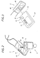
- la figure 2 est une vue schématique d'un émetteur d'appel et d'un émetteur de contrôle;
- la figure 3 est une vue d'un émetteur d'appel et d'un appareil de codage ;
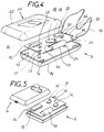
- la figure 4 est une vue éclatée d'un émetteur d'appel ;
- la figure 5 est une vue éclatée d'un émetteur de contrôle.
- Figure 1 is a schematic schematic view of an individual assistance installation identified according to the invention;
- Figure 2 is a schematic view of a call transmitter and a control transmitter;
- Figure 3 is a view of a call transmitter and a coding apparatus;
- Figure 4 is an exploded view of a call transmitter;
- Figure 5 is an exploded view of a control transmitter.
Les installations d'assistance identifiée sont généralement destinées aux établissements d'hébergement de personnes nécessitant une assistance fréquente ou permanente, que l'on appellera personnes surveillées, personnes assistées ou patients.The assistance facilities identified are generally intended for establishments accommodating people requiring frequent or permanent assistance, which will be called supervised persons, assisted persons or patients.
La surveillance et l'assistance est généralement assurée par des membres du personnel appelés personnes de surveillance ou d'assistance, ou encore personnes secourantes.Supervision and assistance is generally carried out by members of the personnel called surveillance or assistance persons, or even rescuers.
Un exemple d'installation d'assistance individuelle identifiée 1 selon l'invention, dont les éléments essentiels sont représentés sur les figures, comprend, d'une part, une centrale de gestion d'appel 2, connectée à une série d'antennes principales 3 et éventuellement une pluralité d'antennes secondaires ou de relais 4, et d'autre part, un ou plusieurs émetteurs d'appel individuels 5 qui sont affectés à chaque personne surveillée, et un ou plusieurs émetteurs de contrôle 6 qui sont affectés aux ou à des membres du personnel de surveillance appelés par leurs fonctions à intervenir en cas d'appel.An example of an individual assistance installation identified 1 according to the invention, the essential elements of which are represented in the figures, comprises, on the one hand, a
Les messages d'appel reçus par la centrale de gestion peuvent être signalisés par des dispositifs d'affichage 7, visuels ou sonores, en étant affectés soit de manière totalement centralisée à un local de surveillance, soit sélectivement par service, par département, par étage, etc. En général, ce mode de signalisation est complété par une signalisation individuelle effectuée par l'intermédiaire d'un dispositif de recherche de personnes 8 relié à des appareils de signalisation portable 9, dits "bips". Il pourra être prévu en outre une imprimante 10 inscrivant successivement les appels.The call messages received by the management center can be signaled by
Ces différents moyens de signalisation et de recherche de personnes sont bien connus dans l'état de la technique.These various means of signaling and paging are well known in the state of the art.
De manière caractéristique, les émetteurs d'appel 5 peuvent transmettre des messages d'appel identifiant le patient ainsi que des messages d'acquit et des messages dits d'urgence ou de second niveau identifiant la personne secourante, sur instruction transmise par l'émetteur de contrôle 6 de celle-ci. Ainsi, notamment, la personne secourante peut, soit "acquitter" un appel, soit demander à son tour une assistance, sans que son message ne revienne alors à elle-même.Typically, the
Les émetteurs d'appel 5, dont un exemple est représenté sur la figure 4, sont constitués par un boîtier 11 contenant un circuit imprimé 12. Les émetteurs d'appel 5 peuvent être portés simplement dans la poche à la manière d'un porte-clé, en broche, ou encore clipsé par exemple. Cependant, de préférence, l'émetteur d'appel 5 selon l'invention comporte un cordon 13 permettant de le porter autour du cou, l'émetteur est ainsi en permanence visible et facile à actionner par le patient. D'autre part, le cordon 13 fait avantageusement fonction d'antenne.The
Le boîtier 11 peut être réalisé par exemple en matière plastique rigide, présentant une forme ergonomique pour une préhension aisée et dépourvue d'arêtes vives, avec des couleurs franches, en vue de faciliter son utilisation par des patients même disposant de moyens physiques et/ou psychiques réduits.The
Le boîtier 11 se compose dans le mode de réalisation représenté de deux demi-coques 14,15 moulées réunies au niveau d'un plan médian formant plan de symétrie, par clipsage ou au moyen de vis.The
Le boîtier est de préférence étanche, et comporte alors un joint périphérique d'étanchéité (non représenté) à l'interface entre les deux demi-coques.The housing is preferably sealed, and then includes a peripheral sealing gasket (not shown) at the interface between the two half-shells.
Le circuit imprimé 12 est disposé sur des supports 16,17 moulés d'une seule pièce avec la demi-coque inférieure 14, et maintenu lors de la fermeture du boîtier par des supports analogues disposés symétriquement, qui sont moulés sur la demi-coque supérieure 15 du boîtier 11.The printed
L'émetteur d'appel 5 comprend un bouton d'actionnement principal 18 qui apparaît de façon bien visible au milieu de la face avant de la demi-coque supérieure 14 lorsque le boîtier 11 est fermé.The
L'émetteur d'appel 5 comprend également un détecteur de signaux radioélectriques 19 en vue de la détection d'instructions d'un des émetteurs de contrôle 6, ces instructions étant appelée ci-après instructions d'assistance.The
Dans le mode de réalisation représenté, la transmission des instructions entre l'émetteur de contrôle 6 et l'émetteur d'appel 5 se fait au moyen de signaux infrarouges. Il est bien entendu que d'autres modes de transmission sont envisageables, notamment, une transmission par ondes radio-électriques dans d'autres plages de fréquence.In the embodiment shown, the transmission of the instructions between the
Le détecteur infrarouge 19 est ici disposé sous le bouton d'actionnement 18, ce dernier étant fabriqué dans un matériau transparent aux signaux infrarouge.The
Il est avantageusement prévu un voyant lumineux 20 de tranquillisation, dont l'allumage est déclenché par l'émission du signal d'appel.Advantageously, a
Selon une particularité de l'invention, il est prévu des moyens d'actionnement supplémentaires.According to a feature of the invention, additional actuation means are provided.
Le bouton d'appel principal 18 est doublé par un ou des boutons d'appel 21,22 actionnés par traction du cordon 13 faisant fonction d'antenne. Ces boutons sont disposés symétriquement à l'extrémité du circuit imprimé 12. Le circuit imprimé 12 est monté coulissant sur une courte distance entre les supports 16,17 qui jouent alors le rôle de glissières. Plus précisément, les éléments supérieur 15 et inférieur 14 du boîtier présentent des plots de centrage 23,24 en regard l'un de l'autre qui viennent en contact lorsque le boitier 1 1 est fermé. Le circuit imprimé 12 est muni de deux ouvertures 25,26 allongées pour le passage des plots de centrage, qui ont ainsi pour effet de limiter la course en coulissement du circuit imprimé 12.The
Lorsque l'on exerce une traction sur le cordon 13, même sur une seule de ses branches, le circuit imprimé 12 est tiré vers l'extrémité correspondante du boîtier 11, de sorte que l'un au moins des boutons 21,22 est écrasé contre la paroi d'extrémité du boîtier.When a pull is exerted on the
Un élément en matériau élastique 27 assure le rappel en position du circuit 12 lorsque la traction sur le cordon cesse.An element made of
Le circuit imprimé 12 comporte un circuit logique contenant un code d'identification individuel, ce circuit logique étant relié à un dispositif d'émission de messages radio 28.The printed
Il est prévu une source d'énergie sous la forme d'une pile 29 qui est montée dans un évidement latéral 30 de forme rectangulaire du circuit et connectée au circuit logique.An energy source is provided in the form of a
Le circuit logique est en outre relié, d'une part, au bouton principal d'appel 18 et aux poussoirs additionnels 21,22 par traction du cordon, et d'autre part au détecteur de signaux 19.The logic circuit is also connected, on the one hand, to the
Selon une particularité de l'invention, chaque émetteur d'appel 5 comprend en outre un détecteur de champ magnétique 31, disposé par exemple à proximité d'une extrémité du boîtier, et relié au circuit logique. Ce détecteur permet de commander l'émission d'un message d'acquit au moyen d'un aimant ou d'un émetteur magnétique, l'acquit étant alors anonyme.According to a feature of the invention, each
Dans une variante non représentée, un second détecteur magnétique pourra être prévu, en un emplacement distinct, par exemple une face latérale, éloigné du premier détecteur magnétique. Ce second détecteur magnétique pourra permettre de commander l'émission d'un message d'appel de second niveau au moyen du même aimant, l'appel de second niveau étant également anonyme.In a variant not shown, a second magnetic detector may be provided, at a separate location, for example a side face, distant from the first magnetic detector. This second magnetic detector may make it possible to control the transmission of a second level call message by means of the same magnet, the second level call also being anonymous.
Dans cette variante, une personne secourante ne disposant pas d'émetteur de contrôle identifié pourra, à l'aide d'un simple aimant, commander l'émission soit d'un message d'acquit, soit d'un message d'appel de second niveau (non identifiés), en fonction de l'emplacement où elle placera cet aimant sur l'émetteur d'appel de la persone secourue.In this variant, a rescuer who does not have an identified control transmitter can, using a simple magnet, order the transmission either of an acknowledgment message or of a call message from second level (not identified), depending on the location where it will place this magnet on the rescued person's call transmitter.
Dans le mode de réalisation décrit, le circuit logique est réalisé par un microcontrôleur 32, qui peut être par exemple un microcontrôleur usuel de type CMOS.In the embodiment described, the logic circuit is produced by a
Le détecteur de signaux 19, qui est ici un détecteur infrarouge, est avantageusement constitué par une diode ou phototransistor infrarouge, couplé à une chaîne d'amplification.The
Le détecteur magnétique 31 est de manière simple une cellule ILS.The
En variante, on pourra employer un capteur à effet Hall, ou magnéto-résistif.Alternatively, a Hall effect or magneto-resistive sensor may be used.
L'émetteur radio est un émetteur en modulation de fréquence. A cet effet, il s'agit par exemple d'un émetteur à quartz.The radio transmitter is a frequency modulation transmitter. For this purpose, it is for example a quartz transmitter.
La modulation de fréquence permet une qualité et une fiabilité élevée de l'émission, par comparaison à la modulation de phase ou d'amplitude sujette à réflexions parasites et atténuations qui limitent pratiquement l'émission à une plus faible portée.Frequency modulation allows high quality and reliability of the transmission, compared to phase or amplitude modulation subject to parasitic reflections and attenuations which practically limit the transmission to a shorter range.
Le fonctionnement du circuit logique est le suivant.The operation of the logic circuit is as follows.
Le microcontrôleur 32 comporte de manière permanente un paramètre ou code d'identification du patient, qui peut être fixé une fois pour toutes lors du montage avant fermeture du boîtier 11, ou être paramétrable par l'intermédiaire du détecteur infrarouge 19.The
En variante, il pourrait être réglé par une série de commutateurs, par exemple trois, disposés sur la plaquette à l'intérieur du boîtier, accessibles uniquement à un technicien par ouverture du boîtier.As a variant, it could be adjusted by a series of switches, for example three, arranged on the wafer inside the housing, accessible only to a technician by opening the housing.
Ce code d'identification est contenu dans chaque message émis par le dispositif d'émission commandé par le microcontrôleur en fonction des instructions reçues.This identification code is contained in each message sent by the transmission device controlled by the microcontroller according to the instructions received.
Si l'instruction est en provenance du bouton d'appel principal 18 ou d'un ou plusieurs des boutons d'appel additionnels 21,22, le microcontrôleur 32 commande alors l'émission d'un signal d'appel.If the instruction comes from the
Si l'instruction provient du ou des détecteurs magnétiques 31, le microcontrôleur 32 commande alors l'émission soit d'un message d'acquit non identifié, soit d'un message d'appel d'urgence non identifié.If the instruction comes from the magnetic detector or
Si l'instruction est en provenance du détecteur infrarouge 19, le microcontrôleur 32 commande alors en fonction des instructions reçues par l'intermédiaire de ce détecteur infrarouge 19 soit un signal de fin d'appel ou d'acquit identifié, contenant le code de la personne secourue et celui de la personne secourante, soit un signal d'appel de second niveau identifié, contenant le code de la personne secourue et le code de la personne secourante.If the instruction comes from the
La centrale 2, qui détecte le signal d'appel en provenance de l'émetteur 5, distingue l'appel de second niveau, contenant le code de la personne secourante, d'un appel "normal", qui serait transmis à l'intention de cette même personne qui est déjà secourante. Cet appel de second niveau est alors transmis à un personnel de veille de second niveau, par exemple le supérieur hiérarchique, ou un collègue.The
On décrira maintenant, en référence à la figure 5, l'émetteur de contrôle 6 qui est affecté au personnel de surveillance.We will now describe, with reference to FIG. 5, the
Il se compose également d'un boîtier 33 contenant un circuit imprimé 34.It also consists of a
Le boîtier 33 de l'émetteur de contrôle 6 présente de préférence une forme et/ou une couleur différentes du boîtier 11 de l'émetteur d'appel 5.The
Il présente sur sa face avant deux boutons 35,36, par exemple de formes ou de couleurs différentes. Le premier bouton 35 est dit bouton d'acquit (identifié) et l'autre bouton 36 est dit bouton d'appel de second degré ou d'urgence.It has on its front face two
Il présente également à son extrémité une ouverture de petite dimension dans laquelle est placé un dispositif de transmission 37 pour la production d'instructions radioélectriques vers un émetteur d'appel. L'émission d'instruction s'effectuant ici par infrarrouge, il s'agit d'une diode infrarouge.It also has at its end a small opening in which is placed a
Le circuit imprimé 34 comporte un circuit logique relié, d'une part, au dispositif de transmission d'instructions 37, qui est ici une diode infrarouge, et d'autre part, aux boutons 35,36 sensibles à l'enfoncement. Ce circuit logique est un microcontrôleur 38 du même type que celui 32 des émetteurs d'appel 5.The printed
Le microcontrôleur 38 comprend de manière permanente un paramètre ou code d'identification de la personne de surveillance, qui peut lui aussi être fixé définitivement lors du montage avant fermeture du boîtier 33, ou bien être paramétrable, par exemple par l'intermédiaire des boutons 35, 36.The
En variante, l'émetteur de contrôle 6 pourrait comporter un détecter par exemple infrarouge par l'intermédiaire duquel une instruction de paramétrage pourrait être transmise.As a variant, the
Ce paramétrage pourrait également dans une variante simple être réglé par l'intermédiaire d'une série de commutateurs par exemple trois disposés sur la plaquette à l'intérieur du boîtier, accessibles uniquement à un technicien par ouverture du boîtier.This configuration could also in a simple variant be adjusted by means of a series of switches, for example three arranged on the wafer inside the housing, accessible only to a technician by opening the housing.
Le circuit logique est conçu de façon que le code d'identification soit contenu dans chaque instruction produite par le dispositif de transmission d'instructions 37 de l'émetteur de contrôle 6, de façon à être contenu dans le message émis par l'émetteur d'appel 5.The logic circuit is designed so that the identification code is contained in each instruction produced by the
Le circuit logique commande ainsi la production d'une instruction infrarouge comprenant un code de fonction (acquit, second appel) et un code d'identification qui est son code propre.The logic circuit thus controls the production of an infrared instruction comprising a function code (acknowledgment, second call) and an identification code which is its own code.
Si l'on appuie sur le premier bouton 35, l'instruction concerne un signal d'acquit identifié.If the
Si l'on appuie sur le second bouton 36, l'instruction concerne un signal d'appel de second niveau, également identifié.If the
Pour transmettre le signal d'instruction à l'émetteur d'appel 5 qui émettra le message en direction de la centrale 2, il suffit d'approcher la diode infrarouge 37, située sur le dessus du boîtier 33 de l'émetteur de contrôle 6, du détecteur infrarouge 19 sur l'émetteur d'appel 5, qui est lui généralement disposé sur la face d'utilisation du boîtier 11 de l'émetteur d'appel 5 (voir figure 2).To transmit the instruction signal to the
Un voyant 39 permettant de confirmer le transfert d'instructions pourra être prévu à proximité des boutons d'actionnement. Le circuit logique est en outre relié à une source d'énergie sous forme d'une pile 40.An indicator light 39 confirming the transfer of instructions may be provided near the actuation buttons. The logic circuit is also connected to an energy source in the form of a
On notera que les codes d'identification des personnes de surveillance pourront être des codes de fonction ou de service, ou des codes individuels, ou encore des codes composés contenant les deux informations.It will be noted that the identification codes of the surveillance persons may be function or service codes, or individual codes, or even composite codes containing the two items of information.
En variante, l'émetteur d'appel pourait être présent sous forme d'émetteur mural. Cette forme de réalisation peut être utilisée en remplacement de l'émetteur portatif. Cependant, elle sera avantageusement présente en tant que complément ou double des émetteurs portatifs.Alternatively, the call transmitter could be present as a wall transmitter. This embodiment can be used as a replacement for the portable transmitter. However, it will advantageously be present as a complement or double of the portable transmitters.
L'émetteur mural se compose également d'un boîtier contenant un circuit imprimé.The wall transmitter also consists of a box containing a printed circuit.
Le déclenchement de l'appel est effectué par l'intermédiaire d'une poire d'appel reliée par un cordon au boîtier. Cette poire remplace le bouton de l'émetteur portable. En variante, d'autres moyen de déclenchement de l'appel sont envisageables, comme des pédales, tirettes, coussins sensibles à l'écrasement, détecteurs de cris, etc.The call is triggered by means of a call bulb connected by a cord to the box. This pear replaces the button on the portable transmitter. As a variant, other means of triggering the call can be envisaged, such as pedals, zippers, cushions sensitive to crushing, cry detectors, etc.
Le boîtier comporte un bouton dit bouton d'acquit, qui sera alors un acquit non identifié, et un deuxième bouton dit bouton d'appel de second niveau, également non identifié. Ces modes de déclenchement peuvent s'avérer utiles dans le cas ou la persone secourante n'a pas sur elle son émetteur de contrôle propre, ni d'émetteur magnétique.The box has a button called the acknowledgment button, which will then be an unidentified acknowledgment, and a second button called the second level call button, also unidentified. These triggering modes can be useful in the case where the rescuing person does not have their own control transmitter or magnetic transmitter on them.
Il est également prévu des boutons de déclenchement par traction sur le cordon de la poire, analogues aux dispositifs de déclenchement par traction sur le cordon de l'émetteur portable, mais à déclenchement par traction vers le bas. L'émetteur mural peut en outre comporter un système de détection d'arrachement du cordon de la poire.There are also provided pull trigger buttons on the pear cord, similar to pull trigger devices on the cord of the portable transmitter, but trigger pull down. The wall transmitter can also include a detachment system for tearing off the pear cord.
De manière spécifique, l'émetteur mural comporte un détecteur de signaux d'instruction, par exemple un détecteur infrarouge, pour la transmission par un émetteur de contrôle d'une instruction d'émission d'un acquit identifié ou d'un appel de second niveau identifié.Specifically, the wall transmitter includes an instruction signal detector, for example an infrared detector, for the transmission by a control transmitter of an instruction to transmit an identified acknowledgment or a second call. level identified.
Chaque émetteur mural pourrait bien sûr comporter une deuxième poire d'appel, chacune des deux poires d'appel ayant son code identifiant propre, ou toutes les deux le même code.Each wall transmitter could of course include a second call bulb, each of the two call pears having its own identifier code, or both the same code.
Pour ses autres caractéristiques, cet émetteur mural est analogue aux émetteurs portables.For its other characteristics, this wall transmitter is analogous to portable transmitters.
Selon une autre variante, L'émetteur d'appel 5 pourrait être un émetteur mixte mural/portable comprenant un élément portable sous la forme d'un émetteur émetteur et un élément fixe faisant fonction de support mural.According to another variant, the
l'émetteur est similaire aux émetteurs portables décrits plus haut, avec une interface supplémentaire pour le contact avec le support en position murale.the transmitter is similar to the portable transmitters described above, with an additional interface for contact with the support in the wall position.
Le support mural comprend des poires d'appel, qui peuvent transmettre une commande d'appel à l'émetteur par l'intermédiaire de l'interface en position murale de celui-ci. Le support présente également avantageusement un voyant de tranquillisation et des boutons d'acquit et d'appel d'urgence, de manière à offrir les mêmes options qu'un émetteur mural permanent.The wall mount includes call pears, which can transmit a call command to the transmitter through the wall mounted interface of the transmitter. The support also advantageously has a tranquilization indicator and acknowledgment and emergency call buttons, so as to offer the same options as a permanent wall transmitter.
Les codes des différents éléments de l'installation sont de la manière la plus simple des codes numériques.The codes of the various elements of the installation are, in the simplest way, numerical codes.
Le codage des émetteurs d'appel s'effectue par l'intermédiaire du bouton d'appel, et le codage des émetteurs de contrôle s'effectue par l'intermédiaire, soit du bouton d'acquit, soit du bouton d'appel de second niveau. Il suffit de maintenir ce bouton enfoncé un temps relativement long, par exemple 10 secondes, de façon à positionner le circuit logique en mode programmation. On appuie ensuite sur le bouton un nombre de fois correspondant au code de l'émetteur, la dernière pression étant elle aussi longue (10 secondes) afin de signaler la sortie du mode programmation. Ce mode de programmation des microcontrôleurs 32 et 38 est connu en soi.The coding of the call transmitters is carried out via the call button, and the coding of the control transmitters is carried out via either the acknowledgment button or the second call button level. It suffices to hold down this button for a relatively long time, for example 10 seconds, so as to position the logic circuit in programming mode. The button is then pressed a number of times corresponding to the transmitter code, the last press being also long (10 seconds) in order to signal the exit from the programming mode. This programming mode of the
En variante, la programmation de l'émetteur d'appel s'effectue au moyen d'un appareil de codage ou codeur 41 par signaux lumineux infrarouges, comprenant une diode infrarouge 42, un ou plusieurs sélecteurs 43,44 et un bouton d'actionnement 45 (figure 3). On place le sélecteur à la position correspondant au code voulu, on approche la diode du détecteur de l'émetteur d'appel ou de l'émetteur de contrôle, et on déclenche les signaux de programmation en appuyant sur le bouton. La transmission est attestée par un voyant de contrôle 46.As a variant, the programming of the call transmitter is carried out by means of a coding device or
Les messages radio transmis à la centrale de gestion comprennent toujours le code numérique de l'émetteur d'appel. S'il s'agit d'un message commandé par un émetteur de contrôle (message d'acquit identifié ou message d'urgence), il contient également le code numérique de l'émetteur de contrôle. La centrale est alors munie d'une table d'équivalence permettant d'associer à chaque code émetteur un libellé propre à l'établissement, qui est transmis aux appareils de signalisation (tableaux lumineux, appels sonores, "bips").Radio messages transmitted to the control center always include the digital code of the caller. If it is a message ordered by a control transmitter (identified acknowledgment message or emergency message), it also contains the digital code of the control transmitter. The control unit is then provided with an equivalence table making it possible to associate with each transmitter code a label specific to the establishment, which is transmitted to the signaling devices (light panels, sound calls, "beeps").
Claims (10)
Applications Claiming Priority (2)
| Application Number | Priority Date | Filing Date | Title |
|---|---|---|---|
| FR9410509A FR2724037A1 (en) | 1994-08-26 | 1994-08-26 | INDIVIDUAL ASSISTANCE INSTALLATION IDENTIFIED |
| FR9410509 | 1994-08-26 |
Publications (3)
| Publication Number | Publication Date |
|---|---|
| EP0702342A2 true EP0702342A2 (en) | 1996-03-20 |
| EP0702342A3 EP0702342A3 (en) | 1996-04-17 |
| EP0702342B1 EP0702342B1 (en) | 2000-12-27 |
Family
ID=9466625
Family Applications (1)
| Application Number | Title | Priority Date | Filing Date |
|---|---|---|---|
| EP95480114A Expired - Lifetime EP0702342B1 (en) | 1994-08-26 | 1995-08-23 | Installation for individual and identifiable assistance |
Country Status (4)
| Country | Link |
|---|---|
| EP (1) | EP0702342B1 (en) |
| AT (1) | ATE198383T1 (en) |
| DE (1) | DE69519709D1 (en) |
| FR (1) | FR2724037A1 (en) |
Cited By (1)
| Publication number | Priority date | Publication date | Assignee | Title |
|---|---|---|---|---|
| ES2162572A1 (en) * | 1999-07-26 | 2001-12-16 | Garrido Jesus Maria Idoate | Safety system for stopping machines in an emergency. |
Family Cites Families (4)
| Publication number | Priority date | Publication date | Assignee | Title |
|---|---|---|---|---|
| FR2576125B1 (en) * | 1985-01-11 | 1987-10-02 | Hall Gerard | TWO-STATE ALARM DEVICE FOR THE PROTECTION OF GOODS AND PERSONS |
| DE3740632A1 (en) * | 1987-09-12 | 1989-03-30 | Wolfgang G Prenosil | Transmitter device |
| US5086391A (en) * | 1989-02-24 | 1992-02-04 | Chambers Bryan R | Remote controller for activating speech messages and for contacting emergency services |
| US5070320A (en) * | 1989-06-12 | 1991-12-03 | Ralph Ramono | Alarm system |
-
1994
- 1994-08-26 FR FR9410509A patent/FR2724037A1/en active Granted
-
1995
- 1995-08-23 AT AT95480114T patent/ATE198383T1/en active
- 1995-08-23 EP EP95480114A patent/EP0702342B1/en not_active Expired - Lifetime
- 1995-08-23 DE DE69519709T patent/DE69519709D1/en not_active Expired - Lifetime
Non-Patent Citations (1)
| Title |
|---|
| None |
Cited By (1)
| Publication number | Priority date | Publication date | Assignee | Title |
|---|---|---|---|---|
| ES2162572A1 (en) * | 1999-07-26 | 2001-12-16 | Garrido Jesus Maria Idoate | Safety system for stopping machines in an emergency. |
Also Published As
| Publication number | Publication date |
|---|---|
| DE69519709D1 (en) | 2001-02-01 |
| FR2724037A1 (en) | 1996-03-01 |
| FR2724037B1 (en) | 1997-03-07 |
| ATE198383T1 (en) | 2001-01-15 |
| EP0702342B1 (en) | 2000-12-27 |
| EP0702342A3 (en) | 1996-04-17 |
Similar Documents
| Publication | Publication Date | Title |
|---|---|---|
| CA2432805C (en) | Multiple-triggering alarm system by transmitters and portable receiver-buzzer | |
| JP5767439B2 (en) | Disaster prevention device and operation switch device for disaster prevention device | |
| FR3047574B1 (en) | INTELLIGENT AND COMMUNICABLE CLOTHING APPARATUS, METHOD AND INSTALLATION FOR BIDIRECTIONAL COMMUNICATION WITH SUCH A DRESSING ARTICLE | |
| US11080985B2 (en) | Alarm triggering device and circuitry therefor | |
| GB2067803A (en) | Emergency call system | |
| EP0702342B1 (en) | Installation for individual and identifiable assistance | |
| FR2740426A1 (en) | Ultrasonic communication and alarm mechanism for underwater divers | |
| EP0628938A1 (en) | Telealarm system | |
| EP1565896B1 (en) | Safety system for persons running the risk of drowning | |
| FR2672410A1 (en) | Device for surveillance and anti-theft protection | |
| EP2474957B1 (en) | Emitter of a call system for a facility including a plurality of call locations | |
| FR3032548A1 (en) | ALERTING MANAGEMENT SYSTEM FOR AN ESTABLISHMENT COMPRISING SEVERAL ZONES | |
| WO1998045969A1 (en) | Communication and alert device for underwater divers | |
| WO2007024187A1 (en) | A safety system, a safety terminal and an alarm system | |
| FR2604319A1 (en) | Telephone set, especially for emergency calls to preselected numbers | |
| FR2701616A1 (en) | Electronic radio-frequency transmission system | |
| BE1018065A3 (en) | Courier presence detecting and signaling and courier introduction system for mailbox located at distance from e.g. house, has control unit activating emitting unit to send signal indicating automatic resetting of indicating unit | |
| CA2292735A1 (en) | Device for identifying and locating a person | |
| FR2627883A3 (en) | Portable radio control with protected buttons for gates - has upper half-shell enclosing radio module with moulded seats for flexible cover units bearing on control buttons beneath | |
| WO2005029434A1 (en) | Emitters/receivers and portable receiver/vibrating unit having multiple actuations | |
| EP0452194A1 (en) | Method and device for monitoring persons using a motion sensing detector | |
| EP1035721A1 (en) | Remote control interface for a telephone set for transmitting an alarm signal and a telephone set comprising said interface | |
| JPH10269483A (en) | Doorphone slave equipment with alarm display lamp | |
| EP0798679A1 (en) | Device for remote call with validation | |
| FR2917875A1 (en) | Child personal object e.g. baby's cuddly toy, identifying and locating device for use in home, has localization unit for locating one of modules through other module alternatively, where modules are equipped with control unit |
Legal Events
| Date | Code | Title | Description |
|---|---|---|---|
| PUAI | Public reference made under article 153(3) epc to a published international application that has entered the european phase |
Free format text: ORIGINAL CODE: 0009012 |
|
| PUAL | Search report despatched |
Free format text: ORIGINAL CODE: 0009013 |
|
| AK | Designated contracting states |
Kind code of ref document: A2 Designated state(s): AT BE CH DE DK ES FR GB GR IE IT LI LU MC NL PT SE |
|
| AK | Designated contracting states |
Kind code of ref document: A3 Designated state(s): AT BE CH DE DK ES FR GB GR IE IT LI LU MC NL PT SE |
|
| 17P | Request for examination filed |
Effective date: 19961014 |
|
| GRAG | Despatch of communication of intention to grant |
Free format text: ORIGINAL CODE: EPIDOS AGRA |
|
| 17Q | First examination report despatched |
Effective date: 19990730 |
|
| GRAG | Despatch of communication of intention to grant |
Free format text: ORIGINAL CODE: EPIDOS AGRA |
|
| GRAG | Despatch of communication of intention to grant |
Free format text: ORIGINAL CODE: EPIDOS AGRA |
|
| GRAH | Despatch of communication of intention to grant a patent |
Free format text: ORIGINAL CODE: EPIDOS IGRA |
|
| GRAH | Despatch of communication of intention to grant a patent |
Free format text: ORIGINAL CODE: EPIDOS IGRA |
|
| GRAA | (expected) grant |
Free format text: ORIGINAL CODE: 0009210 |
|
| AK | Designated contracting states |
Kind code of ref document: B1 Designated state(s): AT BE CH DE DK ES FR GB GR IE IT LI LU MC NL PT SE |
|
| PG25 | Lapsed in a contracting state [announced via postgrant information from national office to epo] |
Ref country code: SE Free format text: THE PATENT HAS BEEN ANNULLED BY A DECISION OF A NATIONAL AUTHORITY Effective date: 20001227 Ref country code: NL Free format text: LAPSE BECAUSE OF FAILURE TO SUBMIT A TRANSLATION OF THE DESCRIPTION OR TO PAY THE FEE WITHIN THE PRESCRIBED TIME-LIMIT Effective date: 20001227 Ref country code: IT Free format text: LAPSE BECAUSE OF FAILURE TO SUBMIT A TRANSLATION OF THE DESCRIPTION OR TO PAY THE FEE WITHIN THE PRESCRIBED TIME-LIMIT;WARNING: LAPSES OF ITALIAN PATENTS WITH EFFECTIVE DATE BEFORE 2007 MAY HAVE OCCURRED AT ANY TIME BEFORE 2007. THE CORRECT EFFECTIVE DATE MAY BE DIFFERENT FROM THE ONE RECORDED. Effective date: 20001227 Ref country code: IE Free format text: LAPSE BECAUSE OF FAILURE TO SUBMIT A TRANSLATION OF THE DESCRIPTION OR TO PAY THE FEE WITHIN THE PRESCRIBED TIME-LIMIT Effective date: 20001227 Ref country code: GR Free format text: LAPSE BECAUSE OF NON-PAYMENT OF DUE FEES Effective date: 20001227 Ref country code: GB Free format text: LAPSE BECAUSE OF FAILURE TO SUBMIT A TRANSLATION OF THE DESCRIPTION OR TO PAY THE FEE WITHIN THE PRESCRIBED TIME-LIMIT Effective date: 20001227 Ref country code: ES Free format text: THE PATENT HAS BEEN ANNULLED BY A DECISION OF A NATIONAL AUTHORITY Effective date: 20001227 Ref country code: AT Free format text: LAPSE BECAUSE OF FAILURE TO SUBMIT A TRANSLATION OF THE DESCRIPTION OR TO PAY THE FEE WITHIN THE PRESCRIBED TIME-LIMIT Effective date: 20001227 |
|
| REF | Corresponds to: |
Ref document number: 198383 Country of ref document: AT Date of ref document: 20010115 Kind code of ref document: T |
|
| REG | Reference to a national code |
Ref country code: CH Ref legal event code: EP |
|
| REF | Corresponds to: |
Ref document number: 69519709 Country of ref document: DE Date of ref document: 20010201 |
|
| REG | Reference to a national code |
Ref country code: IE Ref legal event code: FG4D Free format text: FRENCH |
|
| PG25 | Lapsed in a contracting state [announced via postgrant information from national office to epo] |
Ref country code: PT Free format text: LAPSE BECAUSE OF FAILURE TO SUBMIT A TRANSLATION OF THE DESCRIPTION OR TO PAY THE FEE WITHIN THE PRESCRIBED TIME-LIMIT Effective date: 20010327 Ref country code: DK Free format text: LAPSE BECAUSE OF FAILURE TO SUBMIT A TRANSLATION OF THE DESCRIPTION OR TO PAY THE FEE WITHIN THE PRESCRIBED TIME-LIMIT Effective date: 20010327 |
|
| PG25 | Lapsed in a contracting state [announced via postgrant information from national office to epo] |
Ref country code: DE Free format text: LAPSE BECAUSE OF FAILURE TO SUBMIT A TRANSLATION OF THE DESCRIPTION OR TO PAY THE FEE WITHIN THE PRESCRIBED TIME-LIMIT Effective date: 20010328 |
|
| NLV1 | Nl: lapsed or annulled due to failure to fulfill the requirements of art. 29p and 29m of the patents act | ||
| GBV | Gb: ep patent (uk) treated as always having been void in accordance with gb section 77(7)/1977 [no translation filed] |
Effective date: 20001227 |
|
| PG25 | Lapsed in a contracting state [announced via postgrant information from national office to epo] |
Ref country code: LU Free format text: LAPSE BECAUSE OF NON-PAYMENT OF DUE FEES Effective date: 20010823 |
|
| PG25 | Lapsed in a contracting state [announced via postgrant information from national office to epo] |
Ref country code: LI Free format text: LAPSE BECAUSE OF NON-PAYMENT OF DUE FEES Effective date: 20010831 Ref country code: CH Free format text: LAPSE BECAUSE OF NON-PAYMENT OF DUE FEES Effective date: 20010831 Ref country code: BE Free format text: LAPSE BECAUSE OF NON-PAYMENT OF DUE FEES Effective date: 20010831 |
|
| PLBE | No opposition filed within time limit |
Free format text: ORIGINAL CODE: 0009261 |
|
| STAA | Information on the status of an ep patent application or granted ep patent |
Free format text: STATUS: NO OPPOSITION FILED WITHIN TIME LIMIT |
|
| REG | Reference to a national code |
Ref country code: IE Ref legal event code: FD4D |
|
| 26N | No opposition filed | ||
| BERE | Be: lapsed |
Owner name: MU13 COMMUNICATION-SANTE Effective date: 20010831 |
|
| PG25 | Lapsed in a contracting state [announced via postgrant information from national office to epo] |
Ref country code: MC Free format text: LAPSE BECAUSE OF NON-PAYMENT OF DUE FEES Effective date: 20020301 |
|
| REG | Reference to a national code |
Ref country code: CH Ref legal event code: PL |
|
| PG25 | Lapsed in a contracting state [announced via postgrant information from national office to epo] |
Ref country code: FR Free format text: LAPSE BECAUSE OF NON-PAYMENT OF DUE FEES Effective date: 20020430 |
|
| REG | Reference to a national code |
Ref country code: FR Ref legal event code: ST |