EP0702480A2 - Image processing apparatus and method therefor - Google Patents
Image processing apparatus and method therefor Download PDFInfo
- Publication number
- EP0702480A2 EP0702480A2 EP95306552A EP95306552A EP0702480A2 EP 0702480 A2 EP0702480 A2 EP 0702480A2 EP 95306552 A EP95306552 A EP 95306552A EP 95306552 A EP95306552 A EP 95306552A EP 0702480 A2 EP0702480 A2 EP 0702480A2
- Authority
- EP
- European Patent Office
- Prior art keywords
- image data
- image
- memory
- plural
- memory means
- Prior art date
- Legal status (The legal status is an assumption and is not a legal conclusion. Google has not performed a legal analysis and makes no representation as to the accuracy of the status listed.)
- Granted
Links
Images


Classifications
-
- H—ELECTRICITY
- H04—ELECTRIC COMMUNICATION TECHNIQUE
- H04N—PICTORIAL COMMUNICATION, e.g. TELEVISION
- H04N1/00—Scanning, transmission or reproduction of documents or the like, e.g. facsimile transmission; Details thereof
- H04N1/00127—Connection or combination of a still picture apparatus with another apparatus, e.g. for storage, processing or transmission of still picture signals or of information associated with a still picture
- H04N1/00204—Connection or combination of a still picture apparatus with another apparatus, e.g. for storage, processing or transmission of still picture signals or of information associated with a still picture with a digital computer or a digital computer system, e.g. an internet server
- H04N1/00236—Connection or combination of a still picture apparatus with another apparatus, e.g. for storage, processing or transmission of still picture signals or of information associated with a still picture with a digital computer or a digital computer system, e.g. an internet server using an image reading or reproducing device, e.g. a facsimile reader or printer, as a local input to or local output from a computer
- H04N1/00238—Connection or combination of a still picture apparatus with another apparatus, e.g. for storage, processing or transmission of still picture signals or of information associated with a still picture with a digital computer or a digital computer system, e.g. an internet server using an image reading or reproducing device, e.g. a facsimile reader or printer, as a local input to or local output from a computer using an image reproducing device as a local output from a computer
-
- H—ELECTRICITY
- H04—ELECTRIC COMMUNICATION TECHNIQUE
- H04N—PICTORIAL COMMUNICATION, e.g. TELEVISION
- H04N1/00—Scanning, transmission or reproduction of documents or the like, e.g. facsimile transmission; Details thereof
- H04N1/00127—Connection or combination of a still picture apparatus with another apparatus, e.g. for storage, processing or transmission of still picture signals or of information associated with a still picture
- H04N1/00204—Connection or combination of a still picture apparatus with another apparatus, e.g. for storage, processing or transmission of still picture signals or of information associated with a still picture with a digital computer or a digital computer system, e.g. an internet server
- H04N1/00236—Connection or combination of a still picture apparatus with another apparatus, e.g. for storage, processing or transmission of still picture signals or of information associated with a still picture with a digital computer or a digital computer system, e.g. an internet server using an image reading or reproducing device, e.g. a facsimile reader or printer, as a local input to or local output from a computer
-
- H—ELECTRICITY
- H04—ELECTRIC COMMUNICATION TECHNIQUE
- H04N—PICTORIAL COMMUNICATION, e.g. TELEVISION
- H04N1/00—Scanning, transmission or reproduction of documents or the like, e.g. facsimile transmission; Details thereof
- H04N1/00912—Arrangements for controlling a still picture apparatus or components thereof not otherwise provided for
- H04N1/0096—Simultaneous or quasi-simultaneous functioning of a plurality of operations
-
- H—ELECTRICITY
- H04—ELECTRIC COMMUNICATION TECHNIQUE
- H04N—PICTORIAL COMMUNICATION, e.g. TELEVISION
- H04N1/00—Scanning, transmission or reproduction of documents or the like, e.g. facsimile transmission; Details thereof
- H04N1/32—Circuits or arrangements for control or supervision between transmitter and receiver or between image input and image output device, e.g. between a still-image camera and its memory or between a still-image camera and a printer device
- H04N1/32358—Circuits or arrangements for control or supervision between transmitter and receiver or between image input and image output device, e.g. between a still-image camera and its memory or between a still-image camera and a printer device using picture signal storage, e.g. at transmitter
- H04N1/32443—Circuits or arrangements for control or supervision between transmitter and receiver or between image input and image output device, e.g. between a still-image camera and its memory or between a still-image camera and a printer device using picture signal storage, e.g. at transmitter with asynchronous operation of the image input and output devices connected to the memory
-
- H—ELECTRICITY
- H04—ELECTRIC COMMUNICATION TECHNIQUE
- H04N—PICTORIAL COMMUNICATION, e.g. TELEVISION
- H04N1/00—Scanning, transmission or reproduction of documents or the like, e.g. facsimile transmission; Details thereof
- H04N1/32—Circuits or arrangements for control or supervision between transmitter and receiver or between image input and image output device, e.g. between a still-image camera and its memory or between a still-image camera and a printer device
- H04N1/32358—Circuits or arrangements for control or supervision between transmitter and receiver or between image input and image output device, e.g. between a still-image camera and its memory or between a still-image camera and a printer device using picture signal storage, e.g. at transmitter
- H04N1/32491—Circuits or arrangements for control or supervision between transmitter and receiver or between image input and image output device, e.g. between a still-image camera and its memory or between a still-image camera and a printer device using picture signal storage, e.g. at transmitter alternate storage in and retrieval from two parallel memories, e.g. using ping-pong buffers
-
- H—ELECTRICITY
- H04—ELECTRIC COMMUNICATION TECHNIQUE
- H04N—PICTORIAL COMMUNICATION, e.g. TELEVISION
- H04N1/00—Scanning, transmission or reproduction of documents or the like, e.g. facsimile transmission; Details thereof
- H04N1/32—Circuits or arrangements for control or supervision between transmitter and receiver or between image input and image output device, e.g. between a still-image camera and its memory or between a still-image camera and a printer device
- H04N1/32502—Circuits or arrangements for control or supervision between transmitter and receiver or between image input and image output device, e.g. between a still-image camera and its memory or between a still-image camera and a printer device in systems having a plurality of input or output devices
- H04N1/32523—Circuits or arrangements for control or supervision between transmitter and receiver or between image input and image output device, e.g. between a still-image camera and its memory or between a still-image camera and a printer device in systems having a plurality of input or output devices a plurality of output devices
-
- H—ELECTRICITY
- H04—ELECTRIC COMMUNICATION TECHNIQUE
- H04N—PICTORIAL COMMUNICATION, e.g. TELEVISION
- H04N2201/00—Indexing scheme relating to scanning, transmission or reproduction of documents or the like, and to details thereof
- H04N2201/0008—Connection or combination of a still picture apparatus with another apparatus
- H04N2201/0034—Details of the connection, e.g. connector, interface
-
- H—ELECTRICITY
- H04—ELECTRIC COMMUNICATION TECHNIQUE
- H04N—PICTORIAL COMMUNICATION, e.g. TELEVISION
- H04N2201/00—Indexing scheme relating to scanning, transmission or reproduction of documents or the like, and to details thereof
- H04N2201/0077—Types of the still picture apparatus
- H04N2201/0081—Image reader
-
- H—ELECTRICITY
- H04—ELECTRIC COMMUNICATION TECHNIQUE
- H04N—PICTORIAL COMMUNICATION, e.g. TELEVISION
- H04N2201/00—Indexing scheme relating to scanning, transmission or reproduction of documents or the like, and to details thereof
- H04N2201/0077—Types of the still picture apparatus
- H04N2201/0082—Image hardcopy reproducer
-
- H—ELECTRICITY
- H04—ELECTRIC COMMUNICATION TECHNIQUE
- H04N—PICTORIAL COMMUNICATION, e.g. TELEVISION
- H04N2201/00—Indexing scheme relating to scanning, transmission or reproduction of documents or the like, and to details thereof
- H04N2201/32—Circuits or arrangements for control or supervision between transmitter and receiver or between image input and image output device, e.g. between a still-image camera and its memory or between a still-image camera and a printer device
- H04N2201/3285—Circuits or arrangements for control or supervision between transmitter and receiver or between image input and image output device, e.g. between a still-image camera and its memory or between a still-image camera and a printer device using picture signal storage, e.g. at transmitter
- H04N2201/3298—Checking or indicating the storage space
Abstract

Description
- The present invention relates to an image processing apparatus with a memory, and a method for use therein.
- Owing to recent commercialization of the digital copying apparatus and development of the interface device for connecting such digital copying apparatus with an external equipment such as a host computer, there is becoming popular a system enabling image input from an image source other than the scanner provided in the digital copying apparatus.
- However, such conventional configuration has been associated with the following drawbacks. The above-mentioned interface device is provided with a memory for storing image data transferred from the external equipment and is adapted to execute the printout of the image stored in said memory by the printer of the digital copying apparatus, according to a request from the external equipment, but the transfer of the image data from the external equipment cannot be executed until the completion of print sequence, so that a significant time has been required in case of printing plural images. Also in case of transferring an image from the scanner of the digital copying apparatus to the external equipment, such image data transfer to the external equipment has been inhibited during the execution of the scanner sequence. Consequently, even if the digital copying apparatus is rendered capable of high-speed original scanning such as by an automatic document feeder, the scanned image data stored in the memory of the interface device cannot be transferred to the external equipment, and such point has been an obstacle in constructing the system.
- Various digital color copying apparatus have recently been commercialized, and systems have been developed for printout of data such as of a computer graphic image from a host computer by connecting various interface device to such digital color copying apparatus.
- In such conventional system, the image processing apparatus has been connected only to an image output apparatus for image formation on a recording medium, such as a digital color copying apparatus.
- Such image processing apparatus, connected only to a single image output apparatus, is provided with a frame memory for storing the image data from the host computer. In such configuration, it has been proposed, if the capacity of such frame memory is sufficiently larger than the capacity of the image data to be printed, to divide said memory into two areas and to use one of said areas for image data entry from the host computer during the image data output from the other area to the digital color copying apparatus, thereby achieving image data input and output simultaneously and improving the efficiency of data processing.
- Such data transfer method is called double buffer transfer and enables high-speed image data transfer.
- However, in case of connecting two digital color copying apparatus of different printout processes, for example those of electrophotographic process and of ink jet process, there may result a difference in the method of utilization of the frame memory. More specifically, in the electrophotographic process, the data of an image are collectively stored, at one time, in the frame memory, whereas, in the ink jet process, the data of an image are stored and released in divided manner, in plural times, in the frame memory of a smaller size.
- The color copying apparatus of electrophotographic process is usually designed with a maximum A3 print size, but that of ink jet process is often designed to print up to A1 size at maximum. The image processing apparatus equipped with such two color copying apparatus will require a frame memory corresponding to the A3 size, but a frame memory corresponding to A1 size is not favorable in consideration of the cost. As shown in Figs. 1A and 1B, R, G, B full-color signals for the A3 size require a memory capacity of 96MB. On the other hand, those for the A1 size require a capacity of four times, or 384 MB. On the other hand, the ink jet recording process can achieve printing of an A1-sized image, by storing image data into the frame memory only in a hatched portion shown in Fig. 36 at each time and by repeating such data storage.
- Now, let us consider a case where the image processing apparatus has a frame memory capacity corresponding to A3 size and is provided with a digital color copying apparatus of electrophotographic process and another digital color copying apparatus of ink jet process. In such configuration, if it is desired to print the A4-sized image data only from the digital color copying apparatus of electrophotographic process, high-speed image data transfer is possible by dividing the frame memory into two areas and effecting the double buffer transfer as explained in the foregoing. However if it is desired to effect printing also in the copying apparatus of the ink jet process, proper image output cannot be obtained since the frame memory is fully occupied for the double buffer transfer in the first and second memory areas.
- Besides, while the printout of the electrophotographic process can be completed within an extremely short time, that of the ink jet process requires a very long time, thus occupying the frame memory for a long time.
- In consideration of the foregoing, a concern of the present invention is to achieve, in an image processing apparatus provided with plural output devices, efficient image data output processes without mutual interference of such processes in said plural output devices.
- Another concern of the present invention is, in such image processing apparatus, to achieve efficient utilization of storage means, through appropriate use thereof according to the situation of use.
- Still another concern of the present invention is, in such image processing apparatus, to achieve efficient utilization of a memory area, through appropriate use thereof according to the situation of use.
- According to the present invention there is provided an image processing apparatus comprising:
input means for entering image data;
plural memory means for storing said entered image data;
control means for controlling said plural memory means in respectively corresponding manner to plural image output devices connected to said apparatus; and
output means for transferring the image data from said memory means to said corresponding output devices. - According to the present invention, there is provided an image processing apparatus comprising:
input means for entering image data;
first and second memory means for storing said entered image data;
a first mode in which, during image data output from said first memory means to an output device, said second memory means is used for the input of said image data; and
a second mode in which said first and second memory means are used respectively corresponding to plural output devices connected to said apparatus. - According to the present invention, there is further provided an image processing apparatus comprising:
control means for controlling a memory area;
a first mode in which said control means divides said memory area in plural areas and effects input and output of the image data in parallel manner; and
a second mode in which said control means divides said memory area in plural areas and effects input and output of the image data by causing said divided memory areas to respectively correspond to the output means. - According to the present invention, there is further provided an image processing apparatus comprising:
input means for entering color image data and control information from a host equipment;
memory means for storing said entered color image data; and
control means for selecting either a first mode for controlling said memory means as independent plural memory means or a second mode for controlling said memory means single memory means. - Other aspects of the present invention, and the features thereof, will become fully apparent from the following description which is to be taken in conjunction with the attached drawings.
-
- Fig. 1 comprised of Figs. 1A and 1B is a block diagram of a color image processing system constituting an embodiment of the present invention;
- Fig. 2 is a block diagram showing a part of a
device 101 in Figs. 1A and 1B; - Fig. 3 is a flow chart of a memory card switching sequence;
- Fig. 4 is a flow chart of single buffer mode control (CREATE control);
- Fig. 5 is a flow chart of single buffer mode control (scan control);
- Fig. 6 is a flow chart of single buffer mode control (PUT control);
- Fig. 7 is a flow chart of single buffer mode control (print/GET control);
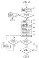
- Fig. 8 is a flow chart of single buffer mode control (print control);
- Fig. 9 is a flow chart of single buffer mode control (GET control);
- Fig. 10 is a view showing the concept of memory space in the single buffer mode;
- Fig. 11 is a flow chart of double buffer mode control (CREATE control);
- Fig. 12 is a flow chart of double buffer mode control (scan control);
- Fig. 13 is a flow chart of CREATE command control in a scan/print sequence in the double buffer mode control;
- Fig. 14 is a flow chart of PUT/GET command control in a scan/print sequence in the double buffer mode control;
- Fig. 15 is a flow chart of double buffer mode control (print control);
- Fig. 16 is a view showing the concept of memory space in the double buffer mode;
- Fig. 17 is a flow chart of a high-speed print sequence in the double buffer mode;
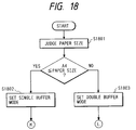
- Fig. 18 is a flow chart of a mode switching sequence in PDL development;
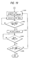
- Fig. 19 is a flow chart of single buffer control in the PDL development;
- Fig. 20 is a flow chart of double buffer control in the PDL development;
- Fig. 21 comprised of Figs. 21A and 21B is a view showing detailed internal structure of a
device 101 in Figs. 1A and 1B; - Fig. 22 is a block diagram of an example of the color conversion circuit;
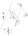
- Fig. 23 is a schematic view showing a first example of the color copying apparatus;
- Fig. 24 is a timing chart showing signal form at the supply of color image data to the color copying apparatus shown in Fig. 23;
- Fig. 25 is a view showing signal configuration among an I/F device, a color copying apparatus and a film scanner in an embodiment of the present invention;
- Fig. 26 is a view showing an example of modular structure of the control program of the
CPU 208 in said embodiment; - Fig. 27 is a view showing the software structure of said embodiment;
- Figs. 28A to 28E are views showing storage formats and contents of device information of the color copying apparatus and the film scanner;
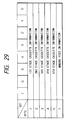
- Fig. 29 is a view showing storage format of information on the sheet cassettes;
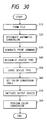
- Fig. 30 is a flow chart of an example of color conversion process of said embodiment;
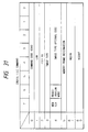
- Fig. 31 is a view showing format and parameters of CREATE FILE command for file preparation;
- Fig. 32 is a view showing registered file information;
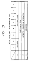
- Fig. 33 is a view showing format of a Native Color Space Auto Conversion PAGE command, for designating auto conversion in the color conversion;
- Fig. 34 is a view showing relationship among device type, file type and color conversion table in the color copying apparatus;
- Fig. 35 is a view showing file type codes;
- Fig. 36 is a view showing a frame memory size required for the image data size, and the printing method of an ink jet digital color copying apparatus; and
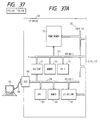
- Fig. 37 comprised of Figs. 37A and 37B is a block diagram showing a color image processing system constituting a second embodiment of the present invention.
- Now the present invention will be clarified in detail by preferred embodiments thereof shown in the attached drawings.
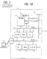
- Figs. 1A and 1B are views schematically showing connections of a system configuration of the present invention. An
interface device 101 constitutes the principal part of the present invention, and is illustrated with schematic internal structure. Ahost computer 102 is connected, by aninterface cable 106 to the I/F device 101, which is a general-purpose interface such as SCSI, whereby computer graphic image data can be transferred from thehost computer 102 to framememories F device 101 and can be printed bycolor copying apparatus color copying apparatus interface cables F device 101 and are used, as explained above, for printing the images stored in theframe memories F device 101. It is also possible to stored images, read by scanners of thecolor copying apparatus frame memories F device 101. Also the entire system can be controlled from operation consoles of thecolor copying apparatus host computer 102.Film scanners F device 101 throughinterface cables frame memories F device 101. Instead of saidfilm scanners F device 101 for image printout. These devices will not be explained further as they are not the principal feature of the present invention. - In the following there will be explained the internal structure of the
interface device 101. A1st CPU 203 controls I/O's other than the externally connected scanners and printers, as will be explained later. ACPU bus 204 of theCPU 203 is connected to aSCSI controller 205 for interfacing with thehost computer 102, aprogram memory 206 and abus controller 207 for controlling an I/O bus 208. There is also connected abus controller 211 for connected with aCPU bus 210 of a2nd CPU 209, which will be explained later. The I/O bus 208 is connected to an I/O controller 212, which controls ahard disk drive 213, afloppy disk drive 214, akeyboard controller 215, aCRT controller 216, anLCD controller 217 etc. A liquidcrystal display device 218 can always display the state of theinterface device 101. Thekeyboard controller 215 is connected to anoperation console 219 for varying the initial setting of theinterface device 101 or for independent setting of service modes. If necessary there may be externally connected a monitor through theCRT controller 216 or a keyboard through thekeyboard controller 215. Furthermore, the I/O bus 208 is provided withauxiliary slots frame memories - The
2nd CPU 209 can control the externally connected scanners and printers, and also can effect processing such as rotation or compression of the image stored in theframe memories program memory 222, control programs are loaded, at the start of power supply, from thehard disk drive 213 through thebus controller 211. Saidmemory 222 is also used in the communication with theCPU 203. TheCPU bus 210 is connected to two scanner/printer interfaces exclusive image bus 225 passes the image data in case of image scanning or printing. The present invention is featured by the use of two scanner/printer interfaces, enabling to use a same frame memory for the printers of different processes, for example of electrophotographic process and ink jet process. These interfaces are made replaceable according to the process or speed of the copying apparatus to be connected, thereby being adaptable to the future systems. - Fig. 2 is a view showing the functions of the
frame memories printer interfaces frame memories memory controllers CPU bus 210 is made independent fromvideo busses 225, so that these two memories can function independently. More specifically, while one of the memories is in a printout operation, the other can effect image transfer from thehost computer 102, development of a postscript image or aforementioned image processing utilizing theCPU 209. Such function is called double buffer function in the present invention. - It is also possible to use these two memories as a single memory space. For example, if each of these memories has a memory capacity corresponding to A4 size, an A3-sized image can be processed by connecting these two memories. Such function is called single buffer function in the present invention.
- The double buffer mode and the single buffer mode are switched by a command released from the
host computer 102 connected through theSCSI controller 205, and these modes are executed according to the control programs stored in thememory 222. - In the following there will be explained the details of the control sequences of the double and single buffer functions.
- The
interface device 101 of the present invention effects communication with theexternal equipment 102, for example a host computer, through theSCSI interface 205, and controls theframe memories printer interfaces memory 222, in response to the following commands released from the external equipment. - (1) Memory mode switching command
This command is used for selecting either of a double buffer mode in which theframe memories frame memories - (2) CREATE command
This command is used for requesting, to the interface device, to secure a memory area in theframe memories
The image identification number is an arbitrary integer from 1 to 128, and an identification number is set for each image. In the present invention, the image data can be registered and stored up to 128 images in the frame memory, and each image in the frame memory is uniquely defined by said image identification numbers.
The present embodiment can handle plural kinds of image, such as RGB 24-bit image, 8-bit pallet image, binary bit map image etc., and the kind of image is designated by the external equipment by this image kind parameter.
The image size designates the weight W and height H of the image to be registered, for example by the number of pixels.
The frame designation parameter is used for designating whether the image data are to be registered in theframe memory - (3) PUT command
This command is used by the external equipment for informing the interface device of the start of transfer (transmission) of the image data, and is composed of parameters indicating the image identification number and the size of the image data to be transferred. - (4) GET command
This command is used by the external equipment for informing the interface device of the start of transfer (reception) of the image data, and is composed of parameters indicating the image identification number and the size of the image data to be transferred. - (5) PRINT command
This command is used for executing printout of the image data, registered in the frame memory, by the printer unit of the color copying apparatus through the scanner/printer interfaces
The layout information designates, at the image printing on the recording sheet, the coordinate (X, Y) of the upper left corner of the image area, taking the upper left corner of the recording sheet as the original point, and the output image size (W, H). The coordinate values can be designated, for example, in millimeters, inches or pixels, but any unit of designation is converted into the unit of pixels by a software in the interface device. - (6) SCAN command
This command is used for executing scanned input of the original image by the scanner unit of the color copying apparatus, through the scanner/printer interfaces
The layout information designates the coordinate (X, Y) of the image reading start position on the original table of the scanner, and the input image size (W, H). The coordinate values can be designated, for example, in millimeters, inches or pixels, but any unit of designation is converted into the unit of pixels by a software in the interface device. - (7) Scanner/printer selecting command
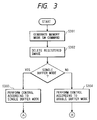
As explained in the foregoing, two scanner/printer interfaces - In the following there will be explained procedure of generation of the above-mentioned commands and control sequence, with reference to a flow chart shown in Fig. 3.
- At first the external equipment releases the memory mode switching command, thereby informing the interface device whether the frame memories are to be used in the single buffer mode or in the double buffer mode (S301). Upon reception of said command, the interface device erases the image data already registered in the frame memories (S302), and executes control in thus designated memory mode, according to the command released from the
host computer 102 constituting the external equipment (S303, S304). - In the following the control sequence will be explained for each mode.
- Fig. 4 is a flow chart showing the control sequence in the single buffer mode. At first the external equipment releases the CREATE command (S401), requesting the interface device to secure a memory area required for the registration of the image data. In the present embodiment, the
frame memory 201 has a capacity of 16 MB for each of R/G/B frames of 48 MB in total, and theframe memory 202 similarly has a capacity of 16 MB for each of R/G/B frames or 48 MB in total. This memory capacity corresponds to the A4 image size with a resolving power of 400 dpi, but, in case of the single buffer mode, the control program of the interface device controls the address space of theframe memories frame memory frame memories host computer 102. - For registering the image data in the memory area secured by the CREATE command, there may be utilized scanned input (S406) of the original image from the scanner unit of the color copying apparatus through the scanner/
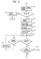
printer interfaces - In case of scanned input of the original image from the scanner unit of the color copying apparatus through the scanner/
printer interfaces interface 223 or that connected to theinterface 224. If the selected scanner/printer interface is not connected to the interface device, or if the color copying apparatus connected to the selected scanner/printer interface is not in an operable state, an error is informed (S502). - If the selected color copying apparatus is in the operable state, a SCAN command is released (S503). The control program of the interface device searches the secured memory address and the image size, based on the image identification number designated by said command (S504). It then calculates the enlargement factor, based on said image size and the designated layout information indicating the position of image formation (S505), and requests, through the scanner/printer interface, the color copying apparatus to start the scanner (S506). The RGB data entered from the scanner are supplied through the scanner/printer interface to the
video bus 225. The memory controller fetches the image data on the video bus and stores said image data in an address managed by the memory management program (S507). - In the single buffer mode, until the completion of the above-explained scanning sequence is informed from the color copying apparatus through the scanner/printer interface, the command request from the external equipment cannot be executed, and a BUSY status is informed to the external equipment (S508).
- On the other hand, in case of transferring the image data held by the external equipment, a PUT command is supplied to the interface device (S601 in Fig. 6). Based on the image identification number designated by said command, the control program of the interface device searches the secured memory address (S602). After setting said address information and the transferred data size in the
SCSI controller 205 and the bus controller 211 (S603), it supplies the external equipment with an acknowledgement ACK (S604), in response to which the external equipment starts the data transfer (S605) of a size designated by the PUT command. The image data transferred from the external equipment is DMA transferred, by a DMA controller provided in theSCSI controller 205, to theframe memories - Plural sets of image data are registered in the frame memories by the repetition of the above-explained sequence (S509, S606).
- In the following there will be explained, with reference to Fig. 8, a case of printing the image data registered in the frame memories, by the printer unit of the color copying apparatus through the scanner/
printer interfaces 223, 224 (S701). - At first a scanner/printer selecting command is released (S801) to select the color copying apparatus connected to the
interface 223 or that connected to theinterface 224, for printout. If the selected scanner/printer interface is not connected to the interface device, or if the color copying apparatus connected to the selected scanner/printer interface is not in an operable state, an error is informed (S802). - If the selected color copying apparatus is in the operable state, a PRINT command is released (S803). The control program of the interface device searches the secured memory address and the image size, based on the image identification number designated by said command (S804). It then calculates the enlargement factor, based on said image size and the layout information (S805), and requests, through the scanner/printer interface, the color copying apparatus to start the printer unit (S806).
- In response to said request, the color copying apparatus activates the internal printer thereof, and sends back an image synchronization signal, synchronized with the operation of said printer. In response, the scanner/printer interface sends an image output request to the memory controller, in synchronization with said image synchronization signal. The memory controller releases the image data from the previously searched memory address to the video bus 255 according to said image output request, whereby said image data are printed by the printer (S807). In the single buffer mode, until the completion of the above-explained printing sequence is informed from the color copying apparatus through the scanner/printer interface, the command request from the external equipment cannot be executed, and a BUSY status is informed to the external apparatus (S808).
- In the following there will be explained, with reference to Fig. 9, a case of transferring the image data, registered in the frame memories, to the external equipment (S702).
- At first a GET command is sent to the interface device (S901). The control program of the interface device searches the secured memory address, based on the image identification number designated by said command (S902). After setting said address information and the transferred data size in the
SCSI controller 205 and the bus controller 211 (S903), it supplies the external equipment with an acknowledgement ACK (S904), in response to which the external equipment starts the data transfer of a size designated by the GET command (S905). The image data registered in theframe memories SCSI controller 205. - The image data registered in the frame memories are retained therein until an image data erasing command is released from the external equipment or the interface device is reset, so that the PRINT or GET command can be executed repeatedly (S809, S906).
- In the double buffer mode, the input of the scanned image from the color copying apparatus through the scanner/
printer interfaces host computer 102 is inhibited during the execution of the scanner or printer sequence of the color copying apparatus, in the double buffer mode, thehost computer 102 can effect image data transfer with the frame memory 201 (or 202) while the image is printed from the frame memory 202 (or 201) or while the scanned image is registered in a memory area secured in the frame memory 202 (or 201). Such operation will be detailedly explained in the following, with reference to a flow chart in Fig. 11. - At first the external equipment (host computer 102) releases a CREATE command (S1101), thus requesting the interface device to secure a memory area required for image data registration. In the present embodiment, the
frame memory 201 has a capacity of 16 MB for each of R/G/B frames or 48 MB in total, and theframe memory 202 similarly has a capacity of 16 MB for each of R/G/B/ frames or 48MB in total. This memory capacity corresponds to the A4 image size with a resolving power of 400 dpi, but, in case of the double buffer mode, the control program of the interface device controls theframe memories host computer 102 can designate, by said command, whether the memory area is to be secured in theframe memory 201 or in 202. Therefore, as shown in Fig. 16 which shows the concept of the frame memories and the memory space secured therein for image registration, the area of image registration is assigned in either of the memory spaces of theframe memories frame memories - Consequently, different from the case of single buffer mode, it is not possible, in the double buffer mode, to secure an image area corresponding to the A3 image size, though the total memory capacity is 96 MB.
- For registering the image data in the memory area secured by the CREATE command, there may be utilized, as in the case of single buffer mode, scanned input of the original image from the scanner unit of the color copying apparatus through the scanner/
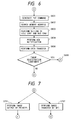
printer interfaces host computer 102, as shown in a flow chart shown in Fig. 12. At the start of the scanner sequence (S1201), the control program of the interface device memorizes whether the image data are entered into theframe memory host computer 102 in the course of execution of the scanner sequence. At first the frame designating parameter of said command is identified (S1301), and, if the designated frame does not coincide with the frame under current image data input, the CREATE command is executed for the designated frame, according to the control sequence explained in the foregoing (S1302). If the designated frame coincides with the frame under current image data input, the CREATE command is not executed and a BUSY status is informed to the host computer 102 (S1303). - Fig. 14 shows the sequence in case a step S1203 receives a PUT or GET command from the
host computer 102 in the course of execution of the scanner sequence. At first the secured memory address is searched, based on the image identification number designated by said command (S1401). If said address does not coincide with the address space of the frame memory under current image data input, the PUT or GET command is executed for the designated frame, according to the control sequence explained before (S1402). If the designated frame coincides with the frame under current image data input, the PUT or GET command is not executed in order to avoid conflict the transmission between the image data input from the scanner and reception of image data with thehost computer 102, and a BUSY status is informed thereto (S1403). - In case a PRINT or SCAN command is received from the
host computer 102, in a step S1204, in the course of execution of the scanner sequence, a BUSY status is informed thereto. - The printout of the image data, registered in the frame memories, by the printer of the color copying apparatus through the scanner/
printer interfaces host computer 102, as shown in a flow chart in Fig. 15. - At the start of the printer sequence (S1501), the control program of the interface device memorizes whether the image data are released from the
frame memory host computer 102 in the course of execution of the printer sequence. At first, the frame designating parameter of said command is identified (S1301), and, if the designated frame does not coincide with the frame under current image data output, the CREATE command is executed for the designated frame according to the control sequence explained before (S1302). If the designated frame coincides with the frame under current image data output, the CREATE command is not executed and a BUSY status is informed to the host computer 102 (S1303). - Fig. 14 shows the sequence in case a PUT or GET command is received, in a step S1503, from the
host computer 102 in the course of execution of the printer sequence. At first, the secured memory address is searched, based on the image identification number designated by said command (S1401). If said address does not coincide with the address space of the frame memory under current image data output, the PUT or GET command is executed for the designated frame, according to the control sequence explained before (S1402). If the designated frame coincides with the frame under current image data output, the PUT or GET command is not executed, in order to avoid conflict between the transmission/reception of the image data with thehost computer 102 and the image printout from the printer, and a BUSY status is informed to the host computer 102 (S1403). - In case a PRINT or SCAN command is received, in a step S1504, from the
host computer 102 in the course of execution of the printer sequence, a BUSY status is informed thereto. Fig. 17 shows a sequence for high-speed image output with thehost computer 102, utilizing the function of the double buffer mode of the present invention. At first a CREATE command is released with theframe memory 201 designated by the frame designating parameter (S1701) to secure a memory space, and an image identification number "1" is assigned thereto. Then a PUT command is executed for said image identification number 1 (step S1702), to transfer and register image data. When this sequence is completed, a PRINT command is released to execute printout of the image data of the image identification number 1 (S1703). During this operation, a CREATE command is released with theframe memory 202 designated by the frame designating parameter (S1704) to secure a memory space, and an image identification number "2" is assigned thereto. Then a PUT command is executed for saidimage identification number 2 to transfer and register the image data (S1705). - After the completion of the above-mentioned sequence and also after the completion of printout sequence for the
image identification number 1, a PRINT command is released to execute printout of the image data of the image identification number 2 (S1706). Thereafter the image registration and the printout execution are repeated similarly for theimage identification numbers host computer 102 can be printed at a high speed. - The foregoing embodiment employs an SCSI interface for connection with the external equipment, but there may also be employed a parallel communication such as GPIB or Centronix, or a serial communication such as RS-232C.
- It is also possible to utilizing a LAN such as Ethernet as the interface with the external equipment, so that the interface device of the present invention may be commonly utilized by plural external equipment such as the host computers.
- Also in the foregoing embodiment the image data transmission/reception between the external equipment and the interface device is achieved in a raster data format, but the single buffer function and the double buffer function of the present invention can be realized also in a configuration where vector data such as a page description language are received from the external equipment and developed into a raster image for printout.
- Fig. 18 shows the control sequence in case of receiving a page description language from the external equipment. In this sequence, at first the output sheet size is identified (S1801), and, if it is equal to or smaller than A4 size, the control program of the interface device proceeds to the double buffer mode (S1803), or to the single buffer mode (S1802) if the sheet size is larger than A4.
- In case of the single buffer mode, the received page description language is interpreted in succession by the CPU 2 (209) (step S1901 in Fig. 19), and is developed into a raster image in a memory space formed by logical connection of the
frame memories 201, 202 (S1902). At the completion of data development of a page, there is requested, through the scanner/printer interface to the color copying apparatus, the start of printing of the raster image developed in the frame memories (S1903). At the completion of the printer sequence (S1904), the interpretation of the page description language of a next page is started (S1901) and the raster image is developed in the frame memories. After the completion of the raster image development, the start of printing is requested (S1902, S1903). The output of pages of a designated number is executed by repetition of the above-explained sequence (S1905). - In case of the double buffer mode, the received page description language is interpreted in succession by the CPU 2209 (step S2001 in Fig. 20), and a 1st page is at first developed into a raster image in the frame memory 201 (S2002). At the completion of the data development of a page, there is requested, through the scanner/printer interface to the color copying apparatus, the start of printing of the raster image developed in the frame memory 201 (S2003). Immediately thereafter started is the interpretation of the page description language corresponding to a 2nd page (S2004), and a raster image is developed in the
frame memory 202. The function state of the printer is discriminated at the completion of the image development in theframe memory 202, and, at the completion of printing of the 1st page, there is requested the start of printing of the raster image developed in the frame memory 202 (S2003). - Thereafter the image development and printing are repeated, by developing the odd pages in the
frame memory 201 and the even pages in theframe memory 202. In the double buffer mode, the image development of the next page can be executed during the printing operation of the preceding page, so that the present invention is applicable effectively also in the control of the page description language or the like. - In the double buffer mode in the foregoing embodiment, the execution of the PRINT or SCAN command from the external equipment is inhibited in the course of printer or scanner sequence even in case the images to be processed are respectively present in the different frame memories, since the
video bus 225 is commonly used by the scanner/printer interfaces printer interfaces - As explained in the foregoing, the first embodiment is provided with means for selecting, according to control information received by the communication means with the external equipment, either a double buffer mode for controlling image data memory means as at least two independent memory means, or a single buffer mode for controlling said image data memory means as single memory means. Thus there can be provided an image processing apparatus capable, in said double buffer mode, of releasing the image data from the 1st memory means for example for printing and simultaneously transferring image data from the host computer to the 2nd memory means, or interpreting the page description language and developing it into a raster image in said 2nd memory, whereby the input/output process of the image data of a large amount can be achieved at a high speed.
- Also the single buffer mode enables input/output of the image data of an amount equal to the maximum capacity of the image data memory means provided in the image processing apparatus. Thus, owing to the above-mentioned control means, the priority on the process speed or on the image size in the image processing apparatus can be arbitrarily selected from the external equipment.
- The 2nd embodiment is featured, in the foregoing 1st embodiment, by having a mode of effecting double buffer transfer process and another mode in which the frame memories are respectively occupied by the plural output apparatus connected to the image processing apparatus.
- As explained in the foregoing, the
interface device 101 shown in Figs. 1A and 1B can be connected to two scanner/printer interfaces, which may be different in the process, for example electrophotographic process and ink jet recording process. - In the following there will be explained, as specific examples, the operations in the electrophotographic process and in the ink jet recording process.
- In the electrophotographic process, the data of an image are collectively stored, at one time, in the frame memory, whereas, in the ink jet process, the data of an image are stored and released in divided manner, in plural times, in the frame memory of a smaller size.
- More specifically, in the ink jet process, the image data registration in the frame memory is conducted only in a hatched area in Fig. 36, and the printout of the image data of Al size is achieved by repeating such image data registration.
- Consequently, the color copying apparatus of electrophotographic process is usually designed with a maximum A3 print size, but that of ink jet process is often designed to print up to A1 size at maximum.
- On the other hand, while the ink jet process requires a very long time for printout, the electrophotographic process can finish printout within a short time.
- This interface is so constructed that interface boards thereof can be replaced according to the process or speed of the connected copying apparatus, and can therefore adapt to the future development.
- Consequently the system is flexibly adaptable to the connected equipment and is thus expandable.
- Also in the present embodiment, two
film scanners printer units printer interfaces - Figs. 21A and 21B are views showing an example of the configuration of scanner/printer interfaces 223-2, 224-2 corresponding to those 223, 224 shown in Fig. 1B and frame
memories - The
frame memories plane memories controllers memory controllers memories - The
frame memories frame memories - More specifically, during image data output for printout from one of the frame memories, the other can be used for image transfer from a
host computer 102 through aCPU bus 210, development of a postscript image or image processing utilizing theCPU 209 as explained before. - Thus the data processing can be made more efficient by simultaneously effecting the image data output and another process such as image data input.
- Consequently a high-speed process can be achieved for example in case of entering plural different images from the
host computer 102 and printing these images in succession from the digital color copying apparatus. - However, such double buffer transfer requires both
frame memories - It is now assumed that a digital color copying apparatus of electrophotographic process and a color copying apparatus of ink jet process are connected to the image processing apparatus. In such case, an image data file for the color copying apparatus of ink jet process may be stored in advance in one of the frame memories. In such situation, the above-mentioned double buffer transfer may be used achieving high-speed data transfer in sending the image data of A4 size to the digital color copying apparatus, the above-mentioned image data file stored in advance is overwritten since the double buffer transfer requires two frame memories. Consequently the printout in the ink jet process cannot be conducted properly as the image data are overwritten.
- Also, while the printout of the electrophotographic process is completed within a very short time, the printout of the ink jet process requires a very long time, thus occupying the frame memory for a long time.
- Consequently, in the present embodiment, the
frame memories CPU 2, whereby the mutual interference is avoided. - Also under the control of the
CPU 2, theframe memories - Thus the apparatus of the present embodiment is provided with a 1st mode for effecting double buffer transfer with two frame memories, a 2nd mode for using the
frame memories frame memories - The
CPU 2 controls these modes by commands set at the image storage in a CREATE FILE shown in Fig. 31. - Thus the user can arbitrarily set these modes according to the purpose.
- Also, as the frame memory can be commonly utilized by plural equipment of different processes, it is not necessary to set the frame memory in advance for each of such equipment, and effective utilization of memory can be achieved.
- The scanner/
printer interfaces color conversion circuit 304 converts the color space of the input image data into image data of a desired color space. A maskingcolor process circuit 305 effects image editing such as masking, UCR process etc. for faithful image reproduction in consideration of the color reproduction characteristics of the connected output equipment. AFIFO 306 adjust the write-in timing of the image data into the frame memory, in case of effecting read-out and write-in of the image data on a same frame memory. Aselector 307 switches the image data path, according to whether the adjustment of the write-in timing is necessary or not. Acontroller 303 controls the various circuits mentioned above. Fig. 22 is a block diagram of thecolor conversion circuit 304. - The
color conversion circuit 304 is composed of two look-up tables (LUT) 304-a, 304-b capable of data setting from 0 to 255, and a 3x3 matrix calculation table 304-c. The LUT 304-a is an exponential calculation table for correcting the characteristics, dependent on the input device, of the image data entered into the color conversion circuit. The 3x3 matrix calculation table 304-c converts the data, corrected by the LUT 304-a, into image on the color space of the output equipment. The LUT 304-b is an exponential calculation table for correcting the image data, subjected to color space conversion by the matrix calculation table 304-c, according to the characteristics of the output equipment. An example of combination of these tables is shown in Fig. 24. - In the present embodiment, the corrections of the input/output characteristics in the LUT's 304-a, 304-b are achieved by preparing plural LUT's in advance according to the color spaces of the input/output equipment, i.e.. according to the types of image and setting a suitable LUT according to the color space conversion, so that the number of LUT's can be limited.
- Also the color space conversion can be achieved exactly without depending on the input characteristics, as it is conducted by the 3x3 matrix conversion table on the data already corrected for the input characteristics.
- Now there is considered a system in which the scanner/
printer interface 223 is connected to an electrophotographiccolor copying apparatus 103 through acable 107, and theinterface 224 is connected to a similarcolor copying apparatus 104 through acable 108. - In the following there will be explained the operation in case of printing an image, stored in the
plain memories 311 of theinterface device 101, by thecolor copying apparatus 103 based on a print command released from thehost computer 102. - The
CPU 203 receives the print command from thehost computer 102 through theSCSI interface 205, then theCPU 209 interprets the received command and writes the content of the received command in amemory 222 under the control of abus controller 211. Upon confirming the write-in, theCPU 209 reads thememory 222 and executes the print command. TheCPU 209 provides thecontroller 303 of theinterface 223 with an instruction to issue a print command to thecolor copying apparatus 103, and saidcontroller 303 sends the print command thereto by communication through thecable 107.Cables color copying apparatus 103 activates the printer and simultaneously sends back an image synchronization signal, in response to which thecontroller 303 releases an image request signal on a controller bus of avideo bus 225 according to said synchronization signal and sends an image output request to thememory controller 301. According to said image request signal, thememory controller 301 releases 24-bit RGB image data to thevideo bus 225. The released image data are supplied to thecolor conversion circuit 304 in theinterface 223, and then converted, in theplain memories 311, from the image data of a predetermined RGB color space into image data of MCY color space of thecolor copying apparatus 103. Then the maskingcolor process circuit 305 effects image editing such as masking, UCR process etc. required for faithful image production matching the color reproduction characteristics of thecolor copying apparatus 103, and the converted C, M, Y, K(black) data are transferred to the color copying apparatus through thecable 107. - The color space is represented by the signal format for example of R, G, B signals or C, M, Y signals and predetermined reference values specific to each equipment.
- The
cable 107 transfers the image data in plane-sequential manner, in the order of M, C, Y and K, utilizing 8 bits in 24-bit image data, in synchronization with the image development in the color copying apparatus. As a result, same RGB data are read four times from theframe memory 201 and are processed in the same manner. - The image data transfer in the present invention is not limited to the plane-sequential manner but can be made in any method adopted in the output equipment, such as dot-sequential manner.
- Fig. 23 schematically shows the image formation from the image data received from the
interface 223, in the electrophotographiccolor copying apparatus 103. 401 indicates image data stored in the frame memory, and there will be explained, as an example, formation of an electrostatic latent image corresponding to magenta color in a line section A-B, on aphotosensitive drum 402. Alaser unit 403 is turned on and off according to the transferred image data, and an electrostatic latent image is formed on aphotosensitive drum 402 through apolygon mirror 404. Thephotosensitive drum 402 is rotated in adirection 404. Abeam sensor 405 detects the end of image to generate a horizontal synchronization signal HSYNC for synchronizing the image transfer, as shown in Fig. 24. The image formation is completed by repeating the above-explained operation four times for C, M, Y and K. In the above-explained operations, the log conversion circuit and the masking circuit are provided in theinterface device 101, but it is also possible to utilize these circuits in the color copying apparatus. In such case the 24-bit image data line in thecable 107 is fully utilized for image data transfer. - In the following there will be explained an operation of storing image data, obtained from the color scanner of the
color copying apparatus 103, into theframe memory 201. - The
CPU 203 receives a scan command from thehost computer 102 through theSCSI interface 205, and recognizes and executes said command. TheCPU 209 sends a scan command by a communication process to thecolor copying apparatus 103 through thecontroller 303. In response, thecolor copying apparatus 103 transfers image data of RGB color space, obtained by scanning an original and based on the input characteristics of thecolor copying apparatus 103, fully utilizing the 24-bit image data lines in thecable 107. In theinterface device 101, the transferred RGB image data are supplied to thecolor conversion circuit 304 of theinterface 223, then subjected to conversion of the color space according to the connected device and the registered file type, and released to thevideo bus 225. At the same time thecontroller 303 release a fetching request signal through the control bus to thememory controller 301, which fetches the image data on thevideo bus 225 and stores said data in the plane memories based on said request signal. The above-explained operations on theframe memory 201 are also conducted similarly on theframe memory 202, which is activated when thecontroller 303 similarly releases a request signal on the control bus for thememory controller 302. For avoiding the conflict of thecontrollers - In the foregoing the image input/output operations of the
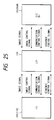
color copying apparatus 103 have been explained, and thecolor copying apparatus 104 and the film scanners function in a similar manner. - Fig. 25 shows the signal configuration between the interface device and other devices such as the color copying apparatus (CLC) and the film scanner. The image signal is transmitted, as explained before, by 24-bit signal lines. The image control signal, for controlling the image data transfer, is composed of a pixel synchronization, a line synchronization signal and a page synchronization signal. The communication control signal effects instruction of operation and management of status by command/status serial communication. The sequence control signal is used for sending information on the power state of various units.
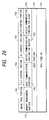
- Fig. 26 shows the modular structure of the control program, to be loaded in the program memory after the start of power supply and to be executed by the
CPU 2. Amodule 701 is the real-time OS for managing plural tasks, which are activated on event-driven basis. Amodule 702 is a task to be executed at the start of the control program, and serves to initialization of various IC's and frame memories, initialization of the parameters and variables used in the control program and identification of the interface board.Modules module 703 executes a task of communication control in which the interface device becomes a master and releases a command, and the color copying apparatus becomes a slave and sends back a status. Themodule 704 effects an inverse task of communication control in which the color copying apparatus releases a command and the interface device return a status. Amodule 705 effects command communication and image transfer control with theCPU 1, whereby theCPU 2 analyzes the command received from the host computer through the SCSI controller and sends a starting instruction for the communication control task and the image processing task.Modules module 709 controls image processing, such as image compression, image expansion, image rotation, mirror image formation and color space conversion. Amodule 710 manages the image files to be registered in theframe memories - Fig. 27 shows the structure of the software system of the interface device, and the function of said system will be explained with reference to Fig. 27. After the start of power supply, the real-time OS of the
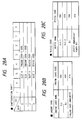
module 701 is activated to generatetasks task 901 controls aboot unit 702, and sets card codes, at the initialization, in a configuration table shown in Fig. 28A. - Said configuration table manages the boards set in the slots or namely in the scanner/
printer interfaces - Though not illustrated, each of the scanner/
printer interfaces CPU 2 can read the identification and automatically recognize the board set in each slot. The board identification indicates the type of communication. Based on said recognition, engine card codes shown in Fig. 28B are written in the corresponding slots in the configuration table. - Then, the power ready state of the color copying apparatus and the film scanners, transmitted by the sequence control signals on the interface, is identified by signal detecting boards (not shown) on the
boards communication control tasks tasks module 703 in which the interface device becomes a master, while thetask 906 effects communication control of themodule 704 in which the interface device becomes a slave, whereby command/status exchange is achieved with the color copying apparatus and the film scanners. Based on the information obtained from this communication, the device codes and cassette information are set in device information tables shown in Figs. 28A to 28E and 29. - Thus, the communication type is set by identifying the inserted interface board and managing the card codes respectively corresponding to the slots. Then communication is made with the connected device according to thus set communication type, and the device codes shown in Figs. 28C and 28E are set, respectively corresponding to the slots, in the configuration tables shown in Figs. 28A and 28D. Through these operations, the
interface device 101 can automatically recognize the connected devices respectively corresponding to the slots. - As the above-explained recognition of the connected devices is conducted at each start of power supply, the latest state of the system can always be understood.
- The
task 902 controls themodule 705 and analyzes the command received from the host computer. When a print/scan command is received, image input/output control tasks communication control tasks - It is thus possible to switch the device to be used for scanning or printing, according to the purpose of the user. It is also possible to effect the image input/output tasks of different control processes, according to the connected equipment.
- Now the setting procedure will be explained with reference to Fig. 30. A step S10 prepares an image file by designating, by a CREATE FILE command shown in Fig. 31, the image type or the color space of the image data storage in the
frame memory 202, through a combination of IMAGE TYPE and IMAGE TYPE optional code. Fig. 35 is a list of correspondences between the image types and the combinations of IMAGE TYPE and IMAGE TYPE optical codes. - In this operation there is prepared a table shown in Fig. 32, as the file information, which is used for managing the image data stored in the
frame memory 202 and contains various information such as the image type designated by the CREATE FILE command at the file preparation, and file ID. - A step S20 sets whether or not to conduct automatic conversation, for converting the image data of the interface device into the color space supported by the output device designated by the print command.
- This step designates or not a Native Color Space Auto Conversion PAGE command shown in Fig. 33, and the automatic color space conversion is not executed if said designation is not made.
- A step S30 releases a print command. It also releases a slot switching command at the same time, if the output equipment connected to the
slot 0, i.e. thecolor copying apparatus 103 in the foregoing example of the system, is not used for printout. - A step S40 activates image input/
output control tasks - A step S50 identifies the type of the output device based on whether the slot switching slot has been issued in the step S30. The interface device is so set that the
slot 0 becomes active s default. However, if the slot switching command has been issued, theslot 1 is rendered active to transmit the image data to thecopying apparatus 104. - A step S60 sets the LUT's 304-a, 304-b in the
color conversion circuit 304 and the 3x3 calculation table 304-c therein as shown in Fig. 34, so as to match the file information shown in Fig. 32, corresponding to the file storing the image data to be printed and the output device identified in the step S50 for image data printout. - A step S70 activates the connected devices through
communication control tasks - As explained in the foregoing, the present embodiment can automatically achieve optimum color space conversion.
- As explained in the foregoing, the second embodiment enables, in an image processing apparatus provided with plural output equipment, efficient output of the image data without mutual interference among such plural output equipment.
- Also effective utilization of memory means is achieved through appropriate used of plural memory means according to the situation of use.
- Also there is achieved efficient utilization of the memory area.
- In the foregoing embodiments there are provided
plural frame memories - In the following there will be explained a modification of the present invention, with reference to Figs. 37A and 37B, wherein components same as those in the foregoing embodiments are represented by same symbols and will not be explained further.
- In the present modification, the frame memory has a capacity for example of A3 size, which is divided into memory areas by the
CPU 3 171 according to the required process, and said memory areas are controlled according to a selected mode. - More specifically a 1st mode effects double buffer transfer process for parallel input/output process of the image data. The
CPU 3 171 divides and controls the frame memory of A3 size into two memories of A4 size each. This 1st mode enables high-speed process though other processes are inhibited. - A 2nd mode controls a designated memory area exclusively for a process, in order to effect processing without mutual interference among the divided memory areas. This 2nd mode is incapable of high-speed processing, but allows to retain the data in other memory areas.
- A 3rd mode effects control without memory area division. Said 3rd mode is incapable of high-speed processing, but allows to handle a large amount of image data, for example up to A3 size in the present embodiment.
- The 1st and 2nd modes are automatically selected by the
CPU 3 171 according to whether single or plural output equipment are connected to the image processing apparatus. - The connected output equipment can be recognized by communication as in the foregoing 2nd embodiment.
- Also the 3rd mode is automatically selected by the
CPU 3 171, according to the amount of input image data. - Thus, this embodiment allows automatic selection of the appropriate modes by the
CPU 3 171. - However, the mode selection may be made by the
CPU 3 171 according to a command, as in the foregoing 1st embodiment. - The output equipment connected to the scanner/printer interface may be an output device provided with a recording head of the type for discharging liquid droplets by film boiling induced by thermal energy.
- The present invention is not limited to the foregoing embodiments but is subject to various-modifications within the scope and spirit of the appended claims.
Claims (21)
- An image processing apparatus comprising:
input means for entering image data;
plural memory means for storing said entered image data;
control means for controlling said plural memory means respectively corresponding to plural image output devices connected to the apparatus; and
output means for sending the image data from said memory means to said corresponding output devices. - An apparatus according to claim 1, wherein said input means is connected to a host computer.
- An apparatus according to claim 1, wherein said memory means is a frame memory.
- An apparatus according to claim 1, wherein said plural output devices are different in output processes.
- An apparatus according to claim 2, wherein;
said input means is adapted to receive a control command from said host computer, and
said control means is adapted to store said input image data in said memory means according to said control command. - An apparatus according to claim 1, wherein said image output device is based on an electrophotographic process.
- An apparatus according to claim 1, wherein said image output device is based on an ink jet recording process.
- An image processing apparatus comprising:
input means for entering image data;
first and second memory means for storing said entered image data;
a first mode in which, during image data output from said first memory to an output device, said second memory means is used for input of said image data; and
a second mode in which said first and second memory means are used respectively corresponding to plural output devices connected to the apparatus. - An apparatus according to claim 8, wherein said input means is connected to a host computer.
- An apparatus according to claim 8, wherein said plural output devices are different in output processes.
- An apparatus according to claim 8, wherein:
said input means is adapted to receive a control command from said host computer, and
said control means is adapted to store said input image data in said memory means according to said control command. - An apparatus according to claim 8, further comprising selection means for selecting the first mode in case only one output device is connected to said apparatus and the second mode in case plural output devices are connected thereto.
- An image processing apparatus comprising:
control means for controlling a memory area;
a first mode in which said control means divides said memory area into plural areas for effecting parallel input/output process of image data; and
a second mode in which said control means divides said memory area into plural areas and controls input/output process of said image data by using said divided areas respectively corresponding to plural output devices. - An apparatus according to claim 13, further comprising:
a third mode in which said control means effect input/output process of the image data utilizing said memory area without division. - An image processing apparatus comprising:
input means for entering color image data and control information from a host equipment;
memory means for storing said input color image data; and
selection means for selecting, according to said control information, whether a first mode in which said memory means is controlled as plural independent memory means or a second mode in which said memory means is controlled as single memory means. - An apparatus according to claim 15, further comprising:
control means for controlling said memory means, including means for switching, in the first mode, either an operation of parallel execution of data transfer between one of the divided memory means and a first external device and data transfer between the other of the divided memory means and a second external device, or an operation of parallel execution of data transfer between one of the divided memory means and a second external device and data transfer between the other of the divided memory means and the first external device. - An apparatus according to claim 15, further comprising:
plural output means for sending the image data, stored in said memory means, to plural output devices. - An apparatus according to claim 15, wherein said plural output devices are different in output processes.
- An image processing method comprising steps of:
entering image data;
storing said entered image data in plural memory means;
controlling said plural memory means respectively corresponding to plural image output devices; and
sending said image data from said memory means to said corresponding output devices. - An image processing method comprising steps of:
entering image data;
storing said entered image data in first and second memory means;
effecting either a first mode in which, during image data output from said first memory to an output device, said second memory means is used for input of said image data; or a second mode in which said first and second memory means are used respectively corresponding to plural output devices. - An image processing method comprising steps of:
entering color image data and control information from a host equipment;
storing said entered image data; and
selecting, according to said control information, whether a first mode in which said memory means is controlled as plural independent memory means or a second mode in which said memory means is controlled as single memory means.
Applications Claiming Priority (6)
| Application Number | Priority Date | Filing Date | Title |
|---|---|---|---|
| JP22320494A JPH0888744A (en) | 1994-09-19 | 1994-09-19 | Image processor |
| JP223204/94 | 1994-09-19 | ||
| JP22320494 | 1994-09-19 | ||
| JP03841895A JP3544021B2 (en) | 1995-02-27 | 1995-02-27 | Image processing apparatus and method |
| JP38418/95 | 1995-02-27 | ||
| JP3841895 | 1995-02-27 |
Publications (3)
| Publication Number | Publication Date |
|---|---|
| EP0702480A2 true EP0702480A2 (en) | 1996-03-20 |
| EP0702480A3 EP0702480A3 (en) | 1996-07-31 |
| EP0702480B1 EP0702480B1 (en) | 2000-04-12 |
Family
ID=26377671
Family Applications (1)
| Application Number | Title | Priority Date | Filing Date |
|---|---|---|---|
| EP95306552A Expired - Lifetime EP0702480B1 (en) | 1994-09-19 | 1995-09-18 | Image processing apparatus and method therefor |
Country Status (3)
| Country | Link |
|---|---|
| US (1) | US6038034A (en) |
| EP (1) | EP0702480B1 (en) |
| DE (1) | DE69516226T2 (en) |
Cited By (1)
| Publication number | Priority date | Publication date | Assignee | Title |
|---|---|---|---|---|
| EP1326417A2 (en) * | 2001-12-28 | 2003-07-09 | Canon Kabushiki Kaisha | Internal interface in image processing apparatus and control thereof |
Families Citing this family (14)
| Publication number | Priority date | Publication date | Assignee | Title |
|---|---|---|---|---|
| JP3851435B2 (en) * | 1997-12-11 | 2006-11-29 | ペンタックス株式会社 | Image reading system |
| JPH11305341A (en) * | 1998-04-16 | 1999-11-05 | Konica Corp | Print forming device and print forming system |
| US6629253B1 (en) * | 1999-12-30 | 2003-09-30 | Intel Corporation | System for efficient management of memory access requests from a planar video overlay data stream using a time delay |
| JP3639770B2 (en) * | 2000-05-19 | 2005-04-20 | キヤノン株式会社 | Network control apparatus and method |
| JP3962563B2 (en) * | 2000-09-12 | 2007-08-22 | キヤノン株式会社 | Image processing apparatus, output data generation method, and program |
| US6888550B2 (en) * | 2001-07-19 | 2005-05-03 | International Business Machines Corporation | Selecting between double buffered stereo and single buffered stereo in a windowing system |
| JP2003046690A (en) * | 2001-07-31 | 2003-02-14 | Canon Inc | Printer and control method therefor |
| US7050097B2 (en) * | 2001-11-13 | 2006-05-23 | Microsoft Corporation | Method and apparatus for the display of still images from image files |
| US20030090498A1 (en) * | 2001-11-13 | 2003-05-15 | Photela, Inc. | Method and apparatus for the creation of digital photo albums |
| JP4741768B2 (en) * | 2001-12-04 | 2011-08-10 | キヤノン株式会社 | Network control device, network control method and program |
| DE10164337A1 (en) * | 2001-12-28 | 2003-07-17 | Broadcasttelevision Systems Me | Method for generating an image composed of two stored images |
| JP5458524B2 (en) * | 2008-08-04 | 2014-04-02 | 富士通モバイルコミュニケーションズ株式会社 | Mobile device |
| EP2172927A1 (en) * | 2008-10-02 | 2010-04-07 | Telefonaktiebolaget LM Ericsson (PUBL) | Method and computer program for operation of a multi-buffer graphics memory refresh, multi-buffer graphics memory arrangement and communication apparatus |
| CN105094714B (en) * | 2014-05-22 | 2018-09-04 | 精工爱普生株式会社 | Printing data processing system, information processing unit and printing equipment |
Family Cites Families (15)
| Publication number | Priority date | Publication date | Assignee | Title |
|---|---|---|---|---|
| US4731672A (en) * | 1983-11-25 | 1988-03-15 | Canon Kabushiki Kaisha | Image processing system |
| US4899291A (en) * | 1984-05-22 | 1990-02-06 | Canon Kabushiki Kaisha | Image processing system |
| US5125045A (en) * | 1987-11-20 | 1992-06-23 | Hitachi, Ltd. | Image processing system |
| JPH01170263A (en) * | 1987-12-25 | 1989-07-05 | Canon Inc | Recorder |
| US5172244A (en) * | 1988-09-12 | 1992-12-15 | Ricoh Company, Ltd. | Digital copier |
| US5051839A (en) * | 1988-09-12 | 1991-09-24 | Ricoh Company, Ltd. | Digital copier |
| US5212566A (en) * | 1990-09-28 | 1993-05-18 | Xerox Corporation | Synchronization of ess/iit when scanning complex documents |
| JP3000744B2 (en) * | 1990-10-10 | 2000-01-17 | 富士ゼロックス株式会社 | Multi-function image processing device |
| US5208676A (en) * | 1990-12-04 | 1993-05-04 | Fuji Xerox Co., Ltd. | Image processing apparatus with data storage region management, memory space allocation in accordance with detected compression ratio of data |
| JP2859450B2 (en) * | 1991-01-31 | 1999-02-17 | 富士写真フイルム株式会社 | Image recording apparatus and image recording method |
| CA2073398A1 (en) * | 1991-09-06 | 1993-03-07 | Larry A. Kovnat | Control subsystem in an image output terminal |
| US5309257A (en) * | 1991-12-31 | 1994-05-03 | Eastman Kodak Company | Method and apparatus for providing color matching between color output devices |
| JPH05242216A (en) * | 1992-02-28 | 1993-09-21 | Ricoh Co Ltd | Picture processor |
| US5375204A (en) * | 1992-04-30 | 1994-12-20 | Ricoh Company, Ltd. | System and method for efficient binary encoding of procedures in a document processing language |
| US5726778A (en) * | 1994-09-16 | 1998-03-10 | Canon Kabushiki Kaisha | Image processing apparatus with color-space conversion |
-
1995
- 1995-09-14 US US08/528,537 patent/US6038034A/en not_active Expired - Lifetime
- 1995-09-18 DE DE69516226T patent/DE69516226T2/en not_active Expired - Lifetime
- 1995-09-18 EP EP95306552A patent/EP0702480B1/en not_active Expired - Lifetime
Non-Patent Citations (1)
| Title |
|---|
| None |
Cited By (3)
| Publication number | Priority date | Publication date | Assignee | Title |
|---|---|---|---|---|
| EP1326417A2 (en) * | 2001-12-28 | 2003-07-09 | Canon Kabushiki Kaisha | Internal interface in image processing apparatus and control thereof |
| EP1326417A3 (en) * | 2001-12-28 | 2004-07-28 | Canon Kabushiki Kaisha | Internal interface in image processing apparatus and control thereof |
| US7626714B2 (en) | 2001-12-28 | 2009-12-01 | Canon Kabushiki Kaisha | Internal interface in image processing apparatus and control thereof |
Also Published As
| Publication number | Publication date |
|---|---|
| DE69516226T2 (en) | 2000-09-07 |
| US6038034A (en) | 2000-03-14 |
| DE69516226D1 (en) | 2000-05-18 |
| EP0702480B1 (en) | 2000-04-12 |
| EP0702480A3 (en) | 1996-07-31 |
Similar Documents
| Publication | Publication Date | Title |
|---|---|---|
| EP0518619B1 (en) | Image processing system with plural memory devices | |
| EP0702480B1 (en) | Image processing apparatus and method therefor | |
| EP0991228B1 (en) | A method, a data processing device, a system and a storage medium enabling direct communication between an image reading device and an image output device | |
| US5726778A (en) | Image processing apparatus with color-space conversion | |
| JP3728063B2 (en) | Image processing system and cooperative operation control method for image processing system | |
| US6226095B1 (en) | Image processing apparatus, method, and system | |
| US6173338B1 (en) | Image output system having memory for storing image data and outputting stored image data based upon output condition and instruction | |
| JPH09219764A (en) | Picture transfer system and picture transfer method | |
| JPH0199364A (en) | Composite copying system | |
| JPH07254991A (en) | System, device and method for processing color image | |
| US5402208A (en) | Image forming apparatus where vibrations of the scanner do not affect the write operation | |
| US6701384B1 (en) | Image output method and system with a function to change a received print condition | |
| JP3544021B2 (en) | Image processing apparatus and method | |
| JP3440117B2 (en) | Printer control device | |
| US7218408B2 (en) | Image printing system | |
| JPH0888744A (en) | Image processor | |
| JP3347641B2 (en) | Interface device, information processing system, and control method of interface device | |
| JP3005463B2 (en) | Printing system | |
| US6731403B1 (en) | Color image process system, color image apparatus, color image processing method | |
| JPH10285388A (en) | Image output system/method and storage medium | |
| JP3647180B2 (en) | Interface device and method thereof | |
| JP3599415B2 (en) | Image processing apparatus and image processing method | |
| JP3478680B2 (en) | Image processing apparatus and image processing method | |
| JP2644212B2 (en) | Color image processing equipment | |
| JP2002373067A (en) | Image processor, image processing method, recording medium and program |
Legal Events
| Date | Code | Title | Description |
|---|---|---|---|
| PUAI | Public reference made under article 153(3) epc to a published international application that has entered the european phase |
Free format text: ORIGINAL CODE: 0009012 |
|
| AK | Designated contracting states |
Kind code of ref document: A2 Designated state(s): DE FR GB IT |
|
| PUAL | Search report despatched |
Free format text: ORIGINAL CODE: 0009013 |
|
| AK | Designated contracting states |
Kind code of ref document: A3 Designated state(s): DE FR GB IT |
|
| 17P | Request for examination filed |
Effective date: 19961211 |
|
| 17Q | First examination report despatched |
Effective date: 19981015 |
|
| GRAG | Despatch of communication of intention to grant |
Free format text: ORIGINAL CODE: EPIDOS AGRA |
|
| GRAG | Despatch of communication of intention to grant |
Free format text: ORIGINAL CODE: EPIDOS AGRA |
|
| GRAH | Despatch of communication of intention to grant a patent |
Free format text: ORIGINAL CODE: EPIDOS IGRA |
|
| GRAH | Despatch of communication of intention to grant a patent |
Free format text: ORIGINAL CODE: EPIDOS IGRA |
|
| GRAA | (expected) grant |
Free format text: ORIGINAL CODE: 0009210 |
|
| AK | Designated contracting states |
Kind code of ref document: B1 Designated state(s): DE FR GB IT |
|
| REF | Corresponds to: |
Ref document number: 69516226 Country of ref document: DE Date of ref document: 20000518 |
|
| ET | Fr: translation filed | ||
| ITF | It: translation for a ep patent filed |
Owner name: SOCIETA' ITALIANA BREVETTI S.P.A. |
|
| PLBE | No opposition filed within time limit |
Free format text: ORIGINAL CODE: 0009261 |
|
| STAA | Information on the status of an ep patent application or granted ep patent |
Free format text: STATUS: NO OPPOSITION FILED WITHIN TIME LIMIT |
|
| 26N | No opposition filed | ||
| REG | Reference to a national code |
Ref country code: GB Ref legal event code: IF02 |
|
| PGFP | Annual fee paid to national office [announced via postgrant information from national office to epo] |
Ref country code: DE Payment date: 20130930 Year of fee payment: 19 |
|
| PGFP | Annual fee paid to national office [announced via postgrant information from national office to epo] |
Ref country code: GB Payment date: 20130924 Year of fee payment: 19 |
|
| PGFP | Annual fee paid to national office [announced via postgrant information from national office to epo] |
Ref country code: IT Payment date: 20130903 Year of fee payment: 19 |
|
| PGFP | Annual fee paid to national office [announced via postgrant information from national office to epo] |
Ref country code: FR Payment date: 20130926 Year of fee payment: 19 |
|
| REG | Reference to a national code |
Ref country code: DE Ref legal event code: R119 Ref document number: 69516226 Country of ref document: DE |
|
| GBPC | Gb: european patent ceased through non-payment of renewal fee |
Effective date: 20140918 |
|
| REG | Reference to a national code |
Ref country code: DE Ref legal event code: R119 Ref document number: 69516226 Country of ref document: DE Effective date: 20150401 |
|
| REG | Reference to a national code |
Ref country code: FR Ref legal event code: ST Effective date: 20150529 |
|
| PG25 | Lapsed in a contracting state [announced via postgrant information from national office to epo] |
Ref country code: GB Free format text: LAPSE BECAUSE OF NON-PAYMENT OF DUE FEES Effective date: 20140918 Ref country code: DE Free format text: LAPSE BECAUSE OF NON-PAYMENT OF DUE FEES Effective date: 20150401 |
|
| PG25 | Lapsed in a contracting state [announced via postgrant information from national office to epo] |
Ref country code: FR Free format text: LAPSE BECAUSE OF NON-PAYMENT OF DUE FEES Effective date: 20140930 Ref country code: IT Free format text: LAPSE BECAUSE OF NON-PAYMENT OF DUE FEES Effective date: 20140918 |