EP0702832B1 - Video editing systems - Google Patents
Video editing systems Download PDFInfo
- Publication number
- EP0702832B1 EP0702832B1 EP94917126A EP94917126A EP0702832B1 EP 0702832 B1 EP0702832 B1 EP 0702832B1 EP 94917126 A EP94917126 A EP 94917126A EP 94917126 A EP94917126 A EP 94917126A EP 0702832 B1 EP0702832 B1 EP 0702832B1
- Authority
- EP
- European Patent Office
- Prior art keywords
- data handling
- handling means
- resolution
- data
- image
- Prior art date
- Legal status (The legal status is an assumption and is not a legal conclusion. Google has not performed a legal analysis and makes no representation as to the accuracy of the status listed.)
- Expired - Lifetime
Links
Images


Classifications
-
- G—PHYSICS
- G11—INFORMATION STORAGE
- G11B—INFORMATION STORAGE BASED ON RELATIVE MOVEMENT BETWEEN RECORD CARRIER AND TRANSDUCER
- G11B27/00—Editing; Indexing; Addressing; Timing or synchronising; Monitoring; Measuring tape travel
- G11B27/02—Editing, e.g. varying the order of information signals recorded on, or reproduced from, record carriers
- G11B27/031—Electronic editing of digitised analogue information signals, e.g. audio or video signals
- G11B27/034—Electronic editing of digitised analogue information signals, e.g. audio or video signals on discs
-
- G—PHYSICS
- G11—INFORMATION STORAGE
- G11B—INFORMATION STORAGE BASED ON RELATIVE MOVEMENT BETWEEN RECORD CARRIER AND TRANSDUCER
- G11B27/00—Editing; Indexing; Addressing; Timing or synchronising; Monitoring; Measuring tape travel
- G11B27/36—Monitoring, i.e. supervising the progress of recording or reproducing
-
- H—ELECTRICITY
- H04—ELECTRIC COMMUNICATION TECHNIQUE
- H04N—PICTORIAL COMMUNICATION, e.g. TELEVISION
- H04N5/00—Details of television systems
- H04N5/222—Studio circuitry; Studio devices; Studio equipment
- H04N5/262—Studio circuits, e.g. for mixing, switching-over, change of character of image, other special effects ; Cameras specially adapted for the electronic generation of special effects
-
- G—PHYSICS
- G11—INFORMATION STORAGE
- G11B—INFORMATION STORAGE BASED ON RELATIVE MOVEMENT BETWEEN RECORD CARRIER AND TRANSDUCER
- G11B2220/00—Record carriers by type
- G11B2220/20—Disc-shaped record carriers
- G11B2220/25—Disc-shaped record carriers characterised in that the disc is based on a specific recording technology
- G11B2220/2508—Magnetic discs
- G11B2220/2512—Floppy disks
Definitions
- This specification relates to video editing systems.
- an edit decision list is produced. This is a list setting out which clips from which source are to be put together in what order to make the final product. There will also be instructions as to fading and so forth.
- an editor will work from a cut-list, cutting specified frames from appropriate reels of material and splicing them together as required. Separate information will be produced for "opticals" where optical printing is needed, say, to combine frames for a fade.
- video tapes it is known to supply the edit decision list in the form of computer software to equipment which will assemble a final video tape from various source tapes.
- the end result is an artistic work on cinematographic film, video tape or other media, which is of "broadcast” quality; that is, the quality and resolution of the images is of the high standard appropriate to the ultimate playback system, be it a projector in a cinema, a tape to be broadcast by a television company, or a tape to be used as a master from which domestic quality tapes or video discs are produced.
- HDTV High Definition Television
- a frame of material in an off line system - of low resolution and compressed - may occupy 20 to 50 Kb.
- the frame may occupy 1 Mb of storage space.
- HDTV material it would occupy 5 Mb of space.
- an object of the invention disclosed herein is to retain the cost effectiveness of off line editing whilst facilitating the production of the broadcast quality product.
- the first data handling means processes the decisions and applies them to the high quality images. Processing time in the first data handling means is used more effectively, and the intention is that shortly after the last edit decision has been made, the high quality output material will be available.
- the material which the operator views and works with in the second data handling means is, in terms of artistic content, identical to that in the first data handling means. All of the same frames are available and coded to enable correlation with the frames in the first data handling means. The difference is that the images are of lower quality.
- the relatively high quality image frames which the first data handling means processes may be of conventional broadcast quality or of higher HDTV quality, or even of film resolution. In practice they may be slightly less than full broadcast quality for some applications.
- a number of sequences will be held in the data handling means, and decisions made concerning the selection of frames.
- selection will be of a number of frames, i.e. a shorter clip from a complete sequence loaded in.
- the latter may be in an idle state between acting upon edit decisions.
- the first data handling means be in communication with a plurality of second data handling means. These may be operating on the same project, or on completely separate projects.
- the first data handling means receives high quality source material, and produces the lower quality material which is provided to the second data handling means.
- the first data handling means preferably includes means for reducing the resolution of the images and/or compressing the data, for supply to the second data handling means.
- the first data handling means must itself process images of high quality. Nevertheless a certain amount of compression is possible without adverse degradation of image quality, say 8 or 10:1. The resolution should be maintained.
- images will be reduced in resolution - for example, by omitting alternate lines or by more sophisticated technique - and compressed by say 20:1 or more for supplying to the second data handling means.
- the resolution of the source material will be maintained but compression of 8 to 10:1 may be used. This will assist operation but without visible degradation of picture quality.
- the first and second data handling means will typically differ in terms of e.g. the memory, storage space, processor speed and so forth.
- the first data handling means will have increased, typically by four times, bandwidth.
- a common processor could be used.
- the two data handling means could be combined in the same physical unit.
- the first data handling means could be used as a stand alone system, having for example sufficient power to handle four pictures at once, at full speed. These will be of lower resolution, perhaps similar or slightly better quality than those of the second data handling means.
- the machine can also work with much more sound simultaneously. It may have at least 8 real channels of production-quality sound, all playable at once. This can be upgraded to 16 real channels. There is a distinction between real channels and the number of tracks that can be laid - so-called virtual tracks. These, of course, have no real limits.
- the machine can play pictures that are much less compressed and therefore of much higher quality. These pictures are of full horizontal resolution, and 50/60 fields. In practice they will be of a quality good enough for some on-line uses, such as news and some corporate work. They may not be full broadcast quality.
- a more practical machine will sustain a single picture or two pictures at 2 Mb/second, plus a great deal of sound. This is equivalent to about 9-minute quality, and looks good.
- JPEG Joint Photo-Interpreters Experts Group
- This method is a highly mathematical technique involving the two-dimensional discrete Cosine transform, as explained in "Digital Imaging Processing" pages 242-247.
- the JPEG technique is currently a Draft International Standard for the coding of Continuous Tone Still Images, ISO DIS 10918, and offers users compression ratios of up to 50:1 with little image degradation.
- the principle of JPEG is as follows:-
- a further scheme is MPEG, the Motion Picture Experts Group. This is described in Draft International Standard ISO/TEC DIS 11172. This offers potentially higher compression ratios, by comparing subsequent frames of a motion picture sequence.
- the Image is represented as a sequential sequence of values, describing the intensity (or brightness) of picture elements (pixels).
- the data structure consists of the brightness value of the first pixel in the first line, followed by the second pixel of the first line, and then subsequent pixels of the first line through to the last pixel of the first line. Then the data structure contains the brightness value of the first pixel of the second line through to the last pixel of the second line. This is continued through to the last line of the image. This is a 'normal' image data structure.
- This data compression technique includes a method for compressing digitised image data in data handling means, wherein:-
- higher resolution images may be compressed by lower amounts.
- a "pyramidal” or “Laplacian” structure there may be a “pyramidal” or “Laplacian” structure.
- At the bottom may be a high resolution image, for example corresponding to broadcast quality source material. This will be compressed by a relatively small amount, such as 8 or 10:1, to minimise picture degradation.
- Higher up the pyramid there will be a picture at lower resolution, for example for use in the video editing system described above. This will be compressed by a greater amount, and for example 20:1.
- the resolution level below this would be, say 2x2 rather than 1x1. Below that, the resolution level will be 4x4 and so forth. Instead of describing a complete level, the difference could be stored between the previous level and the predicted level, predicted by linear interpolation.
- the resolution may be set by omitting alternate lines.
- the resolution may be set by averaging out groups of say four pixels.
- a plurality of compression operations are carried on by parallel compressors. It is known, for example, to use parallel compressors to compress different parts of a particular image. For example four compressions could be used, each for quarter of the image.
- parallel processing techniques are carried out on different respective resolution levels.
- one processor may handle certain low resolution levels whilst one or more can simultaneously handle higher resolution levels.
- a single processor may be able to handle a number of levels in the time that it takes one, two or more to handle a single high resolution level.
- An advantage of this arrangement is that when a compressed image is required, all desired resolutions can be obtained simultaneously.
- source material may be taken in to the first data handling means.
- parallel processors will work on (a) high resolution, mildly compressed files for use in the first data handling means; and (b) lower resolution more highly compressed files for use in the second data handling means.
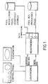
- the "Heavyworks” machine represents the first data handling means which may for example be an EISA system with a 66 MHz Intel 486 DX processor or a 586 processor, and say 16 Mb or more of RAM.
- the "Lightworks” machine represents the second data handling means. This may be an ISA system with a 33 MHz Intel 486 DX processor, again with 16 Mb or more of RAM.
- This unit is provided with a control panel and a monitor.
- the "Heavyworks” unit takes in full resolution digitally stored files, and provides compressed image data for the "Lightworks” unit where edit decisions are made. Control data is then passed back to enable processing of full resolution files.
- the procedure of the communication flow can be considered by the process that the operator would go through in a real job. It is as follows:-
- the first is the Bit Parallel form of Recommendation 601 of the CCIR.
- the second is the bit serial form of the above.
- the third is using the SCSI protocol (Small Computer, Systems Interface). This is usually the protocol used by small computers for talking to their discs, but a 'dual ported' version exists in which there can be two 'masters', which could be the Lightworks and Heavyworks units respectively.
- a fourth format of the communication media could be the FDDI (Fibre Distributed Data Interchange). This is the standard for Fibre Optics systems. Yet another standard could be the 'Ethernet' protocol, of transmitting computer to computer communications over Co-Axial cable.
- Figure 2(a) shows how conventional parallel data compression works. Each quarter of an image is compressed by its own compressor.
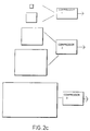
- Figure 2b shows a pyramidal data structure, with different levels covering different resolution. At the top is a single pixel, whose value is the average of the entire image. Lower down are higher resolution images.
- Figure 2c shows how compressors can be used in parallel on these different levels. Thus three compressors work in parallel. One handles the top two layers, one the next two, and one the bottom. As noted earlier, the degree of compression for the lower layers - that are the highest resolution - may be more gentle than for higher levels. Nevertheless, the same degrees of compression could be applied and the concept of using parallel compressors in this way is advantageous.
- Each value requires 8 bits and thus 40 bits are required to store data for this part of the image, in both resolutions.
- the value of the single pixel of the second level is still stored as (A+B+C+D)/4 and requires 8 bits. There are then stored three difference expressions, namely:-
- the three difference equations require 9 bits (8 for the number and 1 for the sign).
- the total data to be stored is 8 bits plus 3 x 9 bits, i.e. 35 bits. This is a saving of 5 bits over storing the pixel values separately.
Description
Nevertheless, the same degrees of compression could be applied and the concept of using parallel compressors in this way is advantageous.
Claims (5)
- A system for editing video material comprising:(a) first digital data handling means for receiving and storing a sequence of image frames of relatively high quality;(b) means for converting the sequence of image frames into a corresponding sequence of image frames of relatively low quality;(c) second digital data handling means for receiving and storing the sequence of relatively low quality image frames;(d) operator input means associated with the second data handling means to enable manipulation of the sequence of relatively low quality image frames for edit decisions to be made;(e) communication means connected between the first and second data handling means, for communicating to the first data handling means edit decisions after manipulation of the frames in the second data handling means; and(f) means within the first data handling means for producing an output sequence of relatively high quality image frames in accordance with the edit decisions communicated from the second data handling means, characterised over this disclosure in that the edit decisions are communicated to the first data handling means substantially as such decisions are made; and in that the system further comprises(g) means within the first data handling means for processing a first edit decision, and for manipulating the relatively high quality image frames accordingly, whilst the operator manipulates the relatively low quality frames in the second data handling means to make a second edit decision for communication to the first data handling means.
- A system as claimed in claim 1, wherein the first data handling means preferably includes means for reducing the resolution of the images and/or compressing the data, for supply to the second data handling means.
- A system as claimed in claim 2, wherein(a) a plurality of different image resolutions are provided from given source material; and(b) data in respect of different respective image resolutions is compressed by different respective amounts.
- A system as claimed in claim 3, wherein, in the first data handling means, parallel processors will work on (a) high resolution, mildly compressed files for use in the first data handling means; and (b) lower resolution more highly compressed files for use in the second data handling means.
- A system as claimed in claim 2, 3 or 4, comprising the steps of:-(a) Providing an image as a series of pixels, at a first resolution;(b) Storing data relating to a second, lower resolution version of the image in which the value of each pixel is calculated as an average of a number of associated pixels at the first resolution; and(c) Storing data from which the values of the associated pixels can be calculated by a simultaneous equation technique.
Applications Claiming Priority (5)
| Application Number | Priority Date | Filing Date | Title |
|---|---|---|---|
| GB9311991 | 1993-06-10 | ||
| GB939311991A GB9311991D0 (en) | 1993-06-10 | 1993-06-10 | Video editing systems |
| GB9320386 | 1993-10-04 | ||
| GB939320386A GB9320386D0 (en) | 1993-10-04 | 1993-10-04 | Video editing systems |
| PCT/GB1994/001255 WO1994029868A2 (en) | 1993-06-10 | 1994-06-10 | Video editing systems |
Publications (2)
| Publication Number | Publication Date |
|---|---|
| EP0702832A1 EP0702832A1 (en) | 1996-03-27 |
| EP0702832B1 true EP0702832B1 (en) | 1998-03-04 |
Family
ID=26303041
Family Applications (1)
| Application Number | Title | Priority Date | Filing Date |
|---|---|---|---|
| EP94917126A Expired - Lifetime EP0702832B1 (en) | 1993-06-10 | 1994-06-10 | Video editing systems |
Country Status (3)
| Country | Link |
|---|---|
| EP (1) | EP0702832B1 (en) |
| DE (1) | DE69408838T2 (en) |
| WO (1) | WO1994029868A2 (en) |
Cited By (8)
| Publication number | Priority date | Publication date | Assignee | Title |
|---|---|---|---|---|
| WO2000069168A1 (en) * | 1999-05-07 | 2000-11-16 | Koninklijke Philips Electronics N.V. | Gathering and editing information with a camera |
| US6351557B1 (en) | 1998-04-03 | 2002-02-26 | Avid Technology, Inc. | Method and apparatus for color manipulation |
| US6417891B1 (en) | 1999-04-16 | 2002-07-09 | Avid Technology, Inc. | Color modification on a digital nonlinear editing system |
| US6477271B1 (en) | 2000-04-07 | 2002-11-05 | Avid Technology, Inc. | Secondary color modification of a digital image |
| US6552731B1 (en) | 1999-04-16 | 2003-04-22 | Avid Technology, Inc. | Multi-tone representation of a digital image on a digital nonlinear editing system |
| US6571255B1 (en) | 1999-04-16 | 2003-05-27 | Robert Gonsalves | Modification of media with common attributes on a digital nonlinear editing system |
| US7973800B2 (en) | 1999-04-16 | 2011-07-05 | Avid Technology, Inc. | Source color modification on a digital nonlinear editing system |
| US8775480B2 (en) | 2011-01-28 | 2014-07-08 | Apple Inc. | Media clip management |
Families Citing this family (17)
| Publication number | Priority date | Publication date | Assignee | Title |
|---|---|---|---|---|
| US5488433A (en) | 1993-04-21 | 1996-01-30 | Kinya Washino | Dual compression format digital video production system |
| EP1414043B1 (en) * | 1994-03-16 | 2008-01-02 | Sony Corporation | Image editing system |
| JPH0991463A (en) * | 1995-07-14 | 1997-04-04 | Matsushita Electric Ind Co Ltd | Image edit device |
| US6628303B1 (en) | 1996-07-29 | 2003-09-30 | Avid Technology, Inc. | Graphical user interface for a motion video planning and editing system for a computer |
| WO1998037558A2 (en) * | 1997-02-21 | 1998-08-27 | Koninklijke Philips Electronics N.V. | Method of and arrangement for recording and reproducing video images |
| US6038573A (en) * | 1997-04-04 | 2000-03-14 | Avid Technology, Inc. | News story markup language and system and process for editing and processing documents |
| JP3741299B2 (en) * | 1997-04-06 | 2006-02-01 | ソニー株式会社 | Video signal processing apparatus and video signal processing method |
| WO2001060062A1 (en) * | 2000-02-08 | 2001-08-16 | Sony Corporation | Method and apparatus for video data recording |
| DE102004025013A1 (en) * | 2004-05-21 | 2005-12-15 | Hüwel, Jan | Method for generating images and image display system |
| US8760472B2 (en) | 2008-04-01 | 2014-06-24 | Apple Inc. | Pixel transforms |
| US8631047B2 (en) | 2010-06-15 | 2014-01-14 | Apple Inc. | Editing 3D video |
| US10324605B2 (en) | 2011-02-16 | 2019-06-18 | Apple Inc. | Media-editing application with novel editing tools |
| US11747972B2 (en) | 2011-02-16 | 2023-09-05 | Apple Inc. | Media-editing application with novel editing tools |
| US9412414B2 (en) | 2011-02-16 | 2016-08-09 | Apple Inc. | Spatial conform operation for a media-editing application |
| US9997196B2 (en) | 2011-02-16 | 2018-06-12 | Apple Inc. | Retiming media presentations |
| US20130124999A1 (en) | 2011-11-14 | 2013-05-16 | Giovanni Agnoli | Reference clips in a media-editing application |
| WO2016095361A1 (en) | 2014-12-14 | 2016-06-23 | SZ DJI Technology Co., Ltd. | Methods and systems of video processing |
Family Cites Families (6)
| Publication number | Priority date | Publication date | Assignee | Title |
|---|---|---|---|---|
| US5057932A (en) * | 1988-12-27 | 1991-10-15 | Explore Technology, Inc. | Audio/video transceiver apparatus including compression means, random access storage means, and microwave transceiver means |
| JP2756301B2 (en) * | 1989-04-10 | 1998-05-25 | キヤノン株式会社 | Image editing method and apparatus |
| US5267351A (en) * | 1989-12-22 | 1993-11-30 | Avid Technology, Inc. | Media storage and retrieval system |
| US5218672A (en) * | 1990-01-19 | 1993-06-08 | Sony Corporation Of America | Offline editing system with user interface for controlling edit list generation |
| GB9022761D0 (en) * | 1990-10-19 | 1990-12-05 | Eidos Plc | Improvements in or relating to video editing systems |
| DE69222102T2 (en) * | 1991-08-02 | 1998-03-26 | Grass Valley Group | Operator interface for video editing system for the display and interactive control of video material |
-
1994
- 1994-06-10 WO PCT/GB1994/001255 patent/WO1994029868A2/en active IP Right Grant
- 1994-06-10 DE DE69408838T patent/DE69408838T2/en not_active Expired - Fee Related
- 1994-06-10 EP EP94917126A patent/EP0702832B1/en not_active Expired - Lifetime
Cited By (14)
| Publication number | Priority date | Publication date | Assignee | Title |
|---|---|---|---|---|
| US6351557B1 (en) | 1998-04-03 | 2002-02-26 | Avid Technology, Inc. | Method and apparatus for color manipulation |
| US6417891B1 (en) | 1999-04-16 | 2002-07-09 | Avid Technology, Inc. | Color modification on a digital nonlinear editing system |
| US7973800B2 (en) | 1999-04-16 | 2011-07-05 | Avid Technology, Inc. | Source color modification on a digital nonlinear editing system |
| US6552731B1 (en) | 1999-04-16 | 2003-04-22 | Avid Technology, Inc. | Multi-tone representation of a digital image on a digital nonlinear editing system |
| US6571255B1 (en) | 1999-04-16 | 2003-05-27 | Robert Gonsalves | Modification of media with common attributes on a digital nonlinear editing system |
| KR100723282B1 (en) * | 1999-05-07 | 2007-05-30 | 비티에스 홀딩 인터내셔널 비.브이. | Gathering and editing information with a camera |
| WO2000069168A1 (en) * | 1999-05-07 | 2000-11-16 | Koninklijke Philips Electronics N.V. | Gathering and editing information with a camera |
| US6763134B2 (en) | 2000-04-07 | 2004-07-13 | Avid Technology, Inc. | Secondary color modification of a digital image |
| US6477271B1 (en) | 2000-04-07 | 2002-11-05 | Avid Technology, Inc. | Secondary color modification of a digital image |
| US8775480B2 (en) | 2011-01-28 | 2014-07-08 | Apple Inc. | Media clip management |
| US8886015B2 (en) | 2011-01-28 | 2014-11-11 | Apple Inc. | Efficient media import |
| US8954477B2 (en) | 2011-01-28 | 2015-02-10 | Apple Inc. | Data structures for a media-editing application |
| US9099161B2 (en) | 2011-01-28 | 2015-08-04 | Apple Inc. | Media-editing application with multiple resolution modes |
| US9251855B2 (en) | 2011-01-28 | 2016-02-02 | Apple Inc. | Efficient media processing |
Also Published As
| Publication number | Publication date |
|---|---|
| DE69408838D1 (en) | 1998-04-09 |
| EP0702832A1 (en) | 1996-03-27 |
| WO1994029868A3 (en) | 1995-02-16 |
| WO1994029868A2 (en) | 1994-12-22 |
| DE69408838T2 (en) | 1998-09-17 |
Similar Documents
| Publication | Publication Date | Title |
|---|---|---|
| EP0702832B1 (en) | Video editing systems | |
| US8774274B2 (en) | Compressing and decompressing multiple, layered, video streams employing multi-directional spatial encoding | |
| US6006276A (en) | Enhanced video data compression in intelligent video information management system | |
| US8644690B2 (en) | Large format video archival, storage, and retrieval system | |
| US5815604A (en) | Interactive image manipulation | |
| EP1237370B1 (en) | A frame-interpolated variable-rate motion imaging system | |
| US6229850B1 (en) | Multiple resolution video compression | |
| US5301018A (en) | Method and apparatus for shuffling image data into statistically averaged data groups and for deshuffling the data | |
| CN1981522A (en) | Stereoscopic television signal processing method, transmission system and viewer enhancements | |
| EP1851683A1 (en) | Digital intermediate (di) processing and distribution with scalable compression in the post-production of motion pictures | |
| JP3331351B2 (en) | Image data encoding method and apparatus | |
| US5905846A (en) | Image decoding apparatus and process thereof and image reproduction apparatus | |
| US5990976A (en) | Video image processing apparatus and the method of the same | |
| US5999657A (en) | Recording and reproducing apparatus for digital image information | |
| US7724964B2 (en) | Digital intermediate (DI) processing and distribution with scalable compression in the post-production of motion pictures | |
| GB2311681A (en) | Video editing systems | |
| US5841935A (en) | Coding method and recording and reproducing apparatus | |
| Ng et al. | On the data compression and transmission aspects of panoramic video | |
| CA2326674C (en) | Video compression in information system | |
| JP2947581B2 (en) | Recording / playback method of DCT compressed video data | |
| US6032242A (en) | Methods and systems for generating alternate and zigzag address scans based on feedback addresses of alternate and zigzag access patterns | |
| JP4380068B2 (en) | Data reproduction device and editing device | |
| JPH07298195A (en) | Image information compressing/expanding device | |
| JPH05143723A (en) | Image reducing method and multi-screen generating method |
Legal Events
| Date | Code | Title | Description |
|---|---|---|---|
| PUAI | Public reference made under article 153(3) epc to a published international application that has entered the european phase |
Free format text: ORIGINAL CODE: 0009012 |
|
| 17P | Request for examination filed |
Effective date: 19960110 |
|
| AK | Designated contracting states |
Kind code of ref document: A1 Designated state(s): DE GB |
|
| 17Q | First examination report despatched |
Effective date: 19960424 |
|
| RHK1 | Main classification (correction) |
Ipc: G11B 27/031 |
|
| GRAG | Despatch of communication of intention to grant |
Free format text: ORIGINAL CODE: EPIDOS AGRA |
|
| GRAG | Despatch of communication of intention to grant |
Free format text: ORIGINAL CODE: EPIDOS AGRA |
|
| GRAH | Despatch of communication of intention to grant a patent |
Free format text: ORIGINAL CODE: EPIDOS IGRA |
|
| GRAH | Despatch of communication of intention to grant a patent |
Free format text: ORIGINAL CODE: EPIDOS IGRA |
|
| GRAA | (expected) grant |
Free format text: ORIGINAL CODE: 0009210 |
|
| AK | Designated contracting states |
Kind code of ref document: B1 Designated state(s): DE GB |
|
| REF | Corresponds to: |
Ref document number: 69408838 Country of ref document: DE Date of ref document: 19980409 |
|
| PLBE | No opposition filed within time limit |
Free format text: ORIGINAL CODE: 0009261 |
|
| STAA | Information on the status of an ep patent application or granted ep patent |
Free format text: STATUS: NO OPPOSITION FILED WITHIN TIME LIMIT |
|
| 26N | No opposition filed | ||
| PGFP | Annual fee paid to national office [announced via postgrant information from national office to epo] |
Ref country code: GB Payment date: 19990517 Year of fee payment: 6 |
|
| PGFP | Annual fee paid to national office [announced via postgrant information from national office to epo] |
Ref country code: DE Payment date: 19990526 Year of fee payment: 6 |
|
| PG25 | Lapsed in a contracting state [announced via postgrant information from national office to epo] |
Ref country code: GB Free format text: LAPSE BECAUSE OF NON-PAYMENT OF DUE FEES Effective date: 20000610 |
|
| GBPC | Gb: european patent ceased through non-payment of renewal fee |
Effective date: 20000610 |
|
| PG25 | Lapsed in a contracting state [announced via postgrant information from national office to epo] |
Ref country code: DE Free format text: LAPSE BECAUSE OF NON-PAYMENT OF DUE FEES Effective date: 20010403 |
|
| REG | Reference to a national code |
Ref country code: GB Ref legal event code: 728V |
|
| REG | Reference to a national code |
Ref country code: GB Ref legal event code: 7281 |