EP0702933A1 - Manipulating and anchoring tissue - Google Patents
Manipulating and anchoring tissue Download PDFInfo
- Publication number
- EP0702933A1 EP0702933A1 EP95118658A EP95118658A EP0702933A1 EP 0702933 A1 EP0702933 A1 EP 0702933A1 EP 95118658 A EP95118658 A EP 95118658A EP 95118658 A EP95118658 A EP 95118658A EP 0702933 A1 EP0702933 A1 EP 0702933A1
- Authority
- EP
- European Patent Office
- Prior art keywords
- anchor member
- tissue
- suture
- needle
- tip
- Prior art date
- Legal status (The legal status is an assumption and is not a legal conclusion. Google has not performed a legal analysis and makes no representation as to the accuracy of the status listed.)
- Granted
Links
Images

Classifications
-
- A—HUMAN NECESSITIES
- A61—MEDICAL OR VETERINARY SCIENCE; HYGIENE
- A61B—DIAGNOSIS; SURGERY; IDENTIFICATION
- A61B17/00—Surgical instruments, devices or methods, e.g. tourniquets
- A61B17/04—Surgical instruments, devices or methods, e.g. tourniquets for suturing wounds; Holders or packages for needles or suture materials
- A61B17/0401—Suture anchors, buttons or pledgets, i.e. means for attaching sutures to bone, cartilage or soft tissue; Instruments for applying or removing suture anchors
-
- A—HUMAN NECESSITIES
- A61—MEDICAL OR VETERINARY SCIENCE; HYGIENE
- A61B—DIAGNOSIS; SURGERY; IDENTIFICATION
- A61B17/00—Surgical instruments, devices or methods, e.g. tourniquets
- A61B17/04—Surgical instruments, devices or methods, e.g. tourniquets for suturing wounds; Holders or packages for needles or suture materials
- A61B17/0469—Suturing instruments for use in minimally invasive surgery, e.g. endoscopic surgery
-
- A—HUMAN NECESSITIES
- A61—MEDICAL OR VETERINARY SCIENCE; HYGIENE
- A61B—DIAGNOSIS; SURGERY; IDENTIFICATION
- A61B17/00—Surgical instruments, devices or methods, e.g. tourniquets
- A61B17/16—Bone cutting, breaking or removal means other than saws, e.g. Osteoclasts; Drills or chisels for bones; Trepans
- A61B17/1604—Chisels; Rongeurs; Punches; Stamps
-
- A—HUMAN NECESSITIES
- A61—MEDICAL OR VETERINARY SCIENCE; HYGIENE
- A61B—DIAGNOSIS; SURGERY; IDENTIFICATION
- A61B17/00—Surgical instruments, devices or methods, e.g. tourniquets
- A61B17/34—Trocars; Puncturing needles
- A61B17/3468—Trocars; Puncturing needles for implanting or removing devices, e.g. prostheses, implants, seeds, wires
-
- A—HUMAN NECESSITIES
- A61—MEDICAL OR VETERINARY SCIENCE; HYGIENE
- A61B—DIAGNOSIS; SURGERY; IDENTIFICATION
- A61B17/00—Surgical instruments, devices or methods, e.g. tourniquets
- A61B17/04—Surgical instruments, devices or methods, e.g. tourniquets for suturing wounds; Holders or packages for needles or suture materials
- A61B17/0401—Suture anchors, buttons or pledgets, i.e. means for attaching sutures to bone, cartilage or soft tissue; Instruments for applying or removing suture anchors
- A61B2017/0404—Buttons
-
- A—HUMAN NECESSITIES
- A61—MEDICAL OR VETERINARY SCIENCE; HYGIENE
- A61B—DIAGNOSIS; SURGERY; IDENTIFICATION
- A61B17/00—Surgical instruments, devices or methods, e.g. tourniquets
- A61B17/04—Surgical instruments, devices or methods, e.g. tourniquets for suturing wounds; Holders or packages for needles or suture materials
- A61B17/0401—Suture anchors, buttons or pledgets, i.e. means for attaching sutures to bone, cartilage or soft tissue; Instruments for applying or removing suture anchors
- A61B2017/0409—Instruments for applying suture anchors
-
- A—HUMAN NECESSITIES
- A61—MEDICAL OR VETERINARY SCIENCE; HYGIENE
- A61B—DIAGNOSIS; SURGERY; IDENTIFICATION
- A61B17/00—Surgical instruments, devices or methods, e.g. tourniquets
- A61B17/04—Surgical instruments, devices or methods, e.g. tourniquets for suturing wounds; Holders or packages for needles or suture materials
- A61B17/0401—Suture anchors, buttons or pledgets, i.e. means for attaching sutures to bone, cartilage or soft tissue; Instruments for applying or removing suture anchors
- A61B2017/0417—T-fasteners
-
- A—HUMAN NECESSITIES
- A61—MEDICAL OR VETERINARY SCIENCE; HYGIENE
- A61B—DIAGNOSIS; SURGERY; IDENTIFICATION
- A61B17/00—Surgical instruments, devices or methods, e.g. tourniquets
- A61B17/04—Surgical instruments, devices or methods, e.g. tourniquets for suturing wounds; Holders or packages for needles or suture materials
- A61B17/0401—Suture anchors, buttons or pledgets, i.e. means for attaching sutures to bone, cartilage or soft tissue; Instruments for applying or removing suture anchors
- A61B2017/0446—Means for attaching and blocking the suture in the suture anchor
- A61B2017/0448—Additional elements on or within the anchor
- A61B2017/0451—Cams or wedges holding the suture by friction
-
- A—HUMAN NECESSITIES
- A61—MEDICAL OR VETERINARY SCIENCE; HYGIENE
- A61B—DIAGNOSIS; SURGERY; IDENTIFICATION
- A61B17/00—Surgical instruments, devices or methods, e.g. tourniquets
- A61B17/04—Surgical instruments, devices or methods, e.g. tourniquets for suturing wounds; Holders or packages for needles or suture materials
- A61B17/06—Needles ; Sutures; Needle-suture combinations; Holders or packages for needles or suture materials
- A61B17/06066—Needles, e.g. needle tip configurations
- A61B2017/061—Needles, e.g. needle tip configurations hollow or tubular
Definitions
- THIS INVENTION relates to an apparatus for manipulating and anchoring cartilage and similar fibrous tissue within a joint.
- the present invention provides a relatively compact and easy to use apparatus for manipulating cartilage and other fibrous tissue, and for anchoring the tissue to other tissue or to bone.
- Some technical references that may be of general interest are as follows: Allen, U.S. Patent 3,699,969; Shein, U.S. Patent 3,527,223; Woo, U.S. Patent 3,943,932; Almen, U.S. Patent 3,500,820; Johnson et al., U.S. Patent 3,871,368; and Smith, U.S. Patent 4,243,037. None of these references discloses a method or apparatus suitable for manipulating fibrous tissue during arthroscopic surgery, or for effectively reattaching fibrous tissue to bone or to other fibrous tissue.
- WO 87/01270 discloses a surgical fastener comprising a head which is relatively stiff along its length and a filament portion which is relatively flexible along its length, the two portions being arranged in a T configuration such that when the relatively stiff head portion is inserted into body tissue, the relatively flexible portion causes the relatively stiff portion to rotate and implant itself in the body tissue thus securing the surgical fastener to the tissue.
- the aforementioned problems associated with use of conventional medical clamps for manipulating tissue are overcome by the present invention, which provides an apparatus and an associated method for manipulating and anchoring tissue during arthroscopic surgery.
- the apparatus provides adequate fixation of the tissue during such surgery and minimally interferes with the use of other instruments within the joint.
- the apparatus particularly comprises an elongated anchor member having a suture attached proximate the midpoint of its length.
- the anchor member is inserted through the tissue with the suture extending therefrom to provide a mechanism for manipulating the tissue within the joint.
- the end faces of the anchor member may be slanted to facilitate movement of the anchor member through the tissue.
- the preferred means of inserting the anchor, member includes a hollow needle having a sharp tip and an open butt.
- a hollow tube of equal or greater length than the needle slides within the needle.
- a limiting mechanism is provided at the butt of the needle and at the corresponding portion of the hollow tube to selectively position the tube within the needle so that the tube does not extend outwardly beyond the tip of the needle.
- the anchor member is located within the tip of the hollow needle in either a deformed U shape, or in its normal, substantially straight shape.
- the suture extends from the anchor member through the bore of the tube.
- a removable shield fits over the tip of the needle to prevent the sharp tip from cutting the suture or the anchor member during the process of inserting the anchor member into the hollow needle.
- the needle tip With the anchor member located within the tip of the needle, the needle tip is inserted into a joint during a surgical procedure.
- the needle tip pierces the tissue to be anchored and passes substantially through the tissue.
- the limiting mechanism is manipulated so that the tube may be pushed forward to the tip of the needle, thereby expelling the anchor member from the tip of the needle into or behind the piece of tissue to be anchored.
- As the anchor member is expelled from the tip of the needle it assumes an orientation generally perpendicular to the length of the suture.
- the needle and tube are then removed from the joint, leaving the suture extending through the tissue and out of the joint.
- the tissue is manipulated by the application of tension on the suture.
- the suture may be rethreaded or left threaded in the tube and the tissue may then be securely held between the tube and the anchor member by applying tension to the suture.
- a hook-ended instrument may be passed through another incision to hook the suture and pull the tissue. It will be apparent that moving the tissue in this manner is possible without detaching the anchor member from the tissue. If necessary, the tissue may be removed from the joint by tension on the suture once the tissue has been surgically freed from the joint.
- One way of using the suture to secure the tissue to the bone is to attach a retainer to the suture for pressing the tissue against the bone.
- the retainer includes resilient suture-engaging edges and corners, and is slidable along the suture in one direction, but grips the suture to resist sliding in the opposite direction. The retainer thereby holds tissue against the bone during healing so that the tissue will properly reattach to the bone.
- the anchor member, suture, and retainer of the present invention may be made of material that is gradually absorbable by the body.
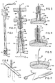
- Fig. 1 is an elevational view of an apparatus for manipulating and anchoring tissue embodying the present invention, with a portion of the apparatus sectionally cut away.
- Fig. 2 is a sectional elevational view of the apparatus shown in Fig. 1, illustrating the manner of deformably lodging an anchor member within the tip of a hollow needle.
- Fig. 3 is a fragmentary, sectional elevational view of the apparatus of Fig. 1, showing the apparatus piercing cartilage.
- Fig. 4 is a fragmentary, sectional elevational view of the apparatus of Fig. 1, illustrating the manner of expelling the anchor member between cartilage and bone.
- Fig. 5 is a sectional elevational view of the apparatus of Fig. 1, showing cartilage secured by the anchor member and suture components of the apparatus.
- Fig. 6 is an enlarged perspective view of the anchor member and suture, showing the normal and deformed configuration of the anchor member.
- Fig. 7 is a foreshortened perspective view of a hook-ended instrument usable with the apparatus of Fig. 1.
- Fig. 8 is a sectional elevational view of an apparatus for manipulating and anchoring tissue, illustrating an alternative manner of lodging the anchor member within the tip of the needle.
- Fig. 9 is a sectional elevational view of the apparatus shown in Fig. 8, illustrating expulsion of the anchor member from the tip of the needle.
- Fig. 10 is a perspective view of the inner surface and an edge of a retainer used in association with the suture and the anchor member for securing tissue to bone or to other tissue.
- Fig. 11 is a perspective view of the outer surface and an edge of the retainer shown in Fig. 10.
- Fig. 12 is a perspective view of an alternative retainer.
- Fig. 13 illustrates a portion of a joint in which the anchor member, suture, and retainer are used to connect and retain a piece of cartilage in position against another piece of cartilage from which it had been torn.
- Fig. 14 is a sectional view taken along line 14-14 of Fig. 13.
- One preferred embodiment of the present invention shown assembled in Figs. 1 and 2, provides a resiliently deformable anchor member 10, which is attached to a suture 12 and adapted to fit deformably within the tip 26 of a hollow needle 14.
- a hollow tube 16 also adapted to fit within the needle 14, is used to expel the anchor member from the tip 26 of the needle after the needle has pierced a piece of fibrous tissue, such as the cartilage 18, as shown in Figs. 3 and 4. Once expelled between the cartilage 18 and bone 38, the anchor member resiliently resumes its normal shape, as shown in Fig. 5.
- the anchor member of the invention might also be used to secure ligament or tendon, as will be described hereinafter, and the term tissue will be broadly used herein to encompass cartilage, tendons, ligaments and similar tissue.
- the anchor member 10 shown in perspective view in Fig. 6, is an elongated cylindrical member.
- the anchor member 10 has end faces 20 and 22 at the respective extremities thereof.
- the end faces 20 and 22 are slanted relative to the longitudinal axis of the anchor member and preferably lie in respective planes that intersect one another.
- the suture 12 is attached to the anchor member 10 at a location 24 between the end faces 20 and 22.
- the suture 12 may be attached to the anchor member 10 during formation of the anchor member.
- the anchor member 10 is preferably comprised of a resilient material such as a plastic. As a result, the anchor member is capable of being deformed from its relaxed, straight shape into a U-shape as shown in broken line in Fig. 6. Although the anchor member is shown to have a circular cross section, other cross-sectional shapes could be utilized without departing from the principles of this invention.
- the anchor member 10 is formed with sufficient rigidity to cause it to resist deformation under moderate pressure, but not so rigid as to prohibit the U-shaped deformation when the anchor member is lodged within the needle as shown in Figs. 2 and 3.
- the material comprising the anchor member has sufficient elasticity to restore the anchor member substantially to its relaxed, straight configuration shown in Figs. 1, 4, 5 and 6.
- the needle 14 shown in Figs. 1 and 2 has a hollow cylindrical shape with a sharp-edged open tip 26, an open butt 27, and a bore extending longitudinally therethrough from the tip 26 to the butt 27.
- the sharp tip 26 is beveled to create a sharp edge at its outer circumference and is thereby adapted to pierce and penetrate tissue.
- the sharp tip 26 could be beveled to create a sharp edge at its inner circumference.
- An annular collar 28 which includes an open keyway 30 formed therein, encircles the butt of the needle.
- the keyway extends a short distance toward the needle tip through the cylindrical wall of the needle as shown in Fig. 2.
- the hollow tube 16 which is at least as long as the needle 14, and has an elongate cylindrical shape with an open tip 17 and an open butt 19, is adapted to slide within the hollow needle.
- the tube 16 has an interior bore diameter large enough to receive the suture 12 therethrough so that the free end 13 of the suture extends from the open butt 19 of the tube.
- the tube 16 has an annular flange 32 encircling the butt 19 thereof to prevent the tube, when pushed toward the needle tip 26, from protruding more than a predetermined distance beyond the tip.
- the tube is preferably such a length that when the flange 32 is positioned immediately adjacent the collar 28, the tip 17 of the tube is proximate the needle tip 26, as shown in Fig. 4.
- a limiting mechanism for controlling movement or the tube 16 is provided in the form of a key 34 that is mounted on the outer cylindrical wall of the tube 16.
- the key 34 is adapted to mate with the keyway 30 associated with the needle 14.
- the key 34 will prevent the tip 17 of the tube 16 from moving proximal to the tip 26 of the needle 14 unless the key 34 is aligned with the keyway 30. This alignment is accomplished by rotation of the tube 16 within the needle 14. If the tube 16 is of the aforementioned preferred length, the key 34 should be located close enough to the tip 17 of the tube 16 to permit the anchor member 10 to be fully drawn into the needle tip 26 when the tube is positioned inside the needle with the key and keyway out of alignment, as shown in Figs. 2 and 3.
- the keyway 30 should be of sufficient length to allow the flange 32 to contact the collar 28 when the key 34 is positioned in the keyway 30. It should be recognized that, while the aforedescribed key and keyway arrangement is believed to be particularly suitable, other mechanisms for limiting the movement of the tube 16 within the needle 14 could be utilized without departing from the principles of this invention.
- a shield 36 having a generally cylindrical shape with open ends is adapted to fit removably on the sharp needle tip 26.
- the inner walls of the shield have three distinct sections: an upper section 29, an intermediate section 31, and a lower section 33.
- the upper section 29 is cylindrical and has an inner diameter substantially equal to the outer diameter of the needle tip 26 so as to permit the shield to be mounted over the tip 26.
- the intermediate section 31 is cylindrical and has an inner diameter slightly smaller than the outer diameter of the needle tip 26, to shield the anchor member from the sharp edge of the needle tip 26.
- the lower section 33 has a bell-like flared shape to encourage appropriate deformation of the anchor member 10 as it is drawn into the needle tip 26 as shown in Fig. 2.
- the apparatus Prior to use, the apparatus is first assembled as shown in Figs. 1 and 2, the shield 36 being mounted upon the tip 26 prior to the suture 12 being threaded through the tube 16 so that the free end 13 protrudes out the butt end 19 of the tube. Tension on the free end 13 of the suture 12 will pull the anchor member 10 into the needle tip 26 as shown in Fig. 2, the inner surface of the bell-shaped lower section 33 of the shield guiding the anchor member into the appropriate U-shape, the anchor member being protected from the sharp tip by the shield 36.
- the tube 16 is axially positioned within the needle with the key 34 abutting the collar 28 so that there is appropriate space for the anchor member to lodge deformably within the needle tip 26.
- Positioning the tube 16 within the needle as shown in Figs. 1 and 2 is not necessary prior to introducing the free end 13 of the suture 12 into and through the bore of the needle 14, but having the tube so positioned when the anchor member 10 is drawn into the tip 26 is helpful to ensure that the anchor member 10 is not positioned an unnecessary distance from the needle tip 26.
- the shield 36 may be removed.
- the assembled apparatus may then be introduced into the joint of a patient, either through an incision or by using the needle tip 26 to pierce the skin and surrounding tissue.
- the tip 26 of the needle 14 is thereafter used to pierce the cartilage 18 which is to be manipulated or anchored, as shown in Fig. 3.
- the tube 16 may be axially rotated within the needle 14 so that the key 34 aligns with the keyway 30. The tube 16 may then be pushed toward the tip 26 of the needle 14, the key 34 entering the keyway 30, and the tip 17 of the tube 16 expelling the anchor member 10 from the needle tip 26 as shown in Fig. 4. As the anchor member 10 is pushed from the needle tip 26, it resumes its normal elongated shape. Where the cartilage 18 is very near bone 38, the slanted end faces 20, 22 of the anchor member facilitate movement of the longitudinal extremities of the anchor member through the space 40 between the bone 38 and cartilage 18.
- the needle 14 and the tube 16 may be withdrawn from the joint, allowing the cartilage 18 to partially collapse around the anchor member 10 and suture 12 as shown in Fig. 5.
- the suture 12 is now anchored to the cartilage 18, and the cartilage may be securely held and manipulated by tension on the suture 12 to facilitate further surgical procedures on and around the cartilage.
- the relatively small size of the suture 12 allows virtually unobstructed vision of the interior of the joint through an arthroscope, and also permits the insertion of other surgical instruments, such as an arthroscope or scalpel, through the same incision as the suture. Due to the flexibility of the suture 12, tension may be applied from many directions as dictated by the needs of the surgical process. Further control of the cartilage 18 is available by rethreading the suture 12 through the tube 16 and applying tension to the suture, thereby effectively clamping the cartilage 18 between the anchor member 10 and the tip 17 of the tube 16, and allowing the cartilage to be pushed, rather than pulled, into a desired position.
- a hook-ended instrument 42 shown in Fig. 7, may be used to achieve even greater maneuverability of the anchored cartilage 18 by introducing the instrument 42 into the joint through a separate incision, capturing the suture 12 in the hooked end of the instrument, and drawing the suture 12 out of the joint through such other incision.
- the cartilage may then be manipulated and controlled in the manner described above, through a different incision, without detaching the anchor member 10 from the anchored cartilage 18.
- the anchored cartilage 18 may be surgically freed, and removed from the joint by tension on the suture 12.
- an anchor member 50 which is similar to the anchor member 10 described above, has fixedly attached thereto a suture 52.
- the anchor member 50 is held within the tip 53 of a hollow needle 54, ahead of the tip 56 of a hollow tube 55.
- the edge of the hollow needle 54 at the tip 53 is formed in a plane that is slanted relative to the longitudinal axis of the needle, thereby to form a sharp leading edge 51 for piercing tissue.
- the free end 57 of the suture 52 extends from the hollow tube 55.
- the anchor member 50 may be used in essentially the same fashion as is the anchor member 10, with the hollow needle 54 piercing a piece of fibrous tissue, such as cartilage 60.
- the anchor member 50 is expelled from the tip 53 of the hollow needle 54 as the hollow tube 55 is slid toward the tip 53 of the hollow needle 54.
- the anchor member 50 thereafter assumes a position between the cartilage 60 and a bone 62, where it extends generally perpendicular to the suture 52.
- the slanted end faces 64, 65 of the anchor member 50 assist in directing the anchor member 50 to this position.
- the suture 52 is pulled outwardly to move the anchor member 50 to the position shown in broken line in Fig. 9, where it extends laterally along the lower surface of the cartilage 60.
- anchor member 50 depicted in Figs. 8 and 9 may be formed of substantially rigid material.
- a rigid anchor member can be inserted into the space between the cartilage and bone by moving the needle 54 so that it is inclined to the bone surface and then expelling the anchor member from the needle.
- a rigid anchor member may be lodged within cartilage or other tissue (i.e. , as opposed to being inserted between cartilage and bone) by expelling the anchor member substantially straight into the tissue and pulling on the suture. Because the suture is attached between the ends of the anchor member, tension on the suture tends to rotate the anchor member into a position substantially perpendicular to the suture, thereby causing the anchor member to become firmly lodged within the tissue.
- retainer devices 68 and 69 are made of resilient material and have slits 70 and 72, respectively, which intersect near the central points of the parallel surfaces, defining pointed corner flaps 71 and 73, respectively.
- the retainers 68 and 69 are preferably circular because the circular shape may reduce the possibility of irritation of surrounding tissue. It will be understood, however, that this shape is a matter of choice and that other shapes would also be acceptable.
- Raised points 74 are provided on the inner surface of the retainer 68 to bear against tissue, and to assist in immobilizing the tissue while the anchor member is in use. In many instances, however, the raised points 74 will not be required and a flat inner surface will suffice.
- retainer use is directed to the anchor member 50 of Fig. 8: however, it is understood that the discussion applies to all embodiments of the anchor member described herein.
- the retainer 68 (or retainer 69) may be used in conjunction with the anchor member 50 by inserting the free end 57 of the suture through the retainer at the intersection of the slits 70 after the hollow needle and hollow tube have been withdrawn from around the suture.
- the flaps 71 that are defined between adjacent slits 70 are resiliently deformed toward the direction of movement of the suture therethrough. Thereafter, the flaps wedge against the suture 52 and resist withdrawal of the suture through the slits.
- the retainer may be used to maintain tension in the suture, thereby holding a loose piece of cartilage 76 against the stable piece of cartilage 78 from which the loose piece of cartilage 76 had been torn or fractured.
- the anchor member 50, suture 52, and retainer 68 may be left permanently in the joint to retain the torn cartilage 76 in its proper location against the stable cartilage 78, with the retainer 68 resting against the outside of the stable cartilage 78, between the surface of the stable cartilage 78 and muscle tissue 79 adjacent thereto.
- the needle 54 may be inserted into a joint from opposing directions.
- the anchor member 50 was deposited in the position shown in Figs. 13 and 14 by a needle that penetrated the muscle tissue 79.
- the needle could have been inserted from the opposing side of the joint (and not through muscle tissue 79) to deposit the anchor or member 50 in the position occupied by the retainer 68 in Figs. 13 and 14.
- the positions of the anchor member 50 and the retainer 68 would be reversed from those shown in Figs. 13 and 14, but the loose cartilage 76 would still be held against the secure cartilage 78.
- One reason for inserting the needle from the opposing side of the joint would be to avoid damaging any nerves or blood vessels that are present in the region of the muscle tissue 79.
- the anchor member and retainer of material that can be gradually absorbed by the body of the patient as healing occurs.
- Resilient, synthetic materials that are gradually absorbable by the body are known for use in sutures and are desirable as materials for the anchor member and retainers of the present invention.
- an absorbable polymer known as poly-diaxanone (PDS), which is available from Ethicon, Inc., of Summerville, New Jersey.
Abstract
Description
- THIS INVENTION relates to an apparatus for manipulating and anchoring cartilage and similar fibrous tissue within a joint.
- Conventional medical clamps have certain disadvantages when used for manipulating cartilage or other tissue within a joint during arthroscopic surgery. Primarily, the clamps have a tendency to slip off the cartilage. Additionally, the size of the clamps in relation to the relatively small space within the joint makes it difficult to maneuver other surgical instruments, such as a scalpel or arthroscope, within the confined space of the joint. Such clamps can also interfere with the view of the inside of the joint afforded by the arthroscope. Since the clamps must be introduced into the joint through an incision, they are limited in their range of manipulation by the location of the incision. In order to apply a desired directional traction to the cartilage, it may be necessary to release the clamp from the cartilage, reintroduce the clamp through another incision, and reclamp the cartilage.
- It is often necessary to repair torn fibrous tissue, such as a ligament or tendon, or reattach such tissue to bone. While in some instances it is possible to insert two needles into the joint and then thread both of them with a suture to form a loop to reattach torn parts of fibrous tissue, that procedure is undesirable because it is complex and time-consuming. The alternative of more radical arthrotomy is also undesirable because of the increased amount of trauma and resultant increased morbidity encountered in the use of such a procedure.
- As is explained in the following summary and description, the present invention provides a relatively compact and easy to use apparatus for manipulating cartilage and other fibrous tissue, and for anchoring the tissue to other tissue or to bone. Some technical references that may be of general interest are as follows: Allen, U.S. Patent 3,699,969; Shein, U.S. Patent 3,527,223; Woo, U.S. Patent 3,943,932; Almen, U.S. Patent 3,500,820; Johnson et al., U.S. Patent 3,871,368; and Smith, U.S. Patent 4,243,037. None of these references discloses a method or apparatus suitable for manipulating fibrous tissue during arthroscopic surgery, or for effectively reattaching fibrous tissue to bone or to other fibrous tissue.
- International publication No. WO 87/01270 discloses a surgical fastener comprising a head which is relatively stiff along its length and a filament portion which is relatively flexible along its length, the two portions being arranged in a T configuration such that when the relatively stiff head portion is inserted into body tissue, the relatively flexible portion causes the relatively stiff portion to rotate and implant itself in the body tissue thus securing the surgical fastener to the tissue.
- The aforementioned problems associated with use of conventional medical clamps for manipulating tissue are overcome by the present invention, which provides an apparatus and an associated method for manipulating and anchoring tissue during arthroscopic surgery. The apparatus provides adequate fixation of the tissue during such surgery and minimally interferes with the use of other instruments within the joint.
- The apparatus particularly comprises an elongated anchor member having a suture attached proximate the midpoint of its length. The anchor member is inserted through the tissue with the suture extending therefrom to provide a mechanism for manipulating the tissue within the joint. The end faces of the anchor member may be slanted to facilitate movement of the anchor member through the tissue.
- The preferred means of inserting the anchor, member includes a hollow needle having a sharp tip and an open butt. A hollow tube of equal or greater length than the needle slides within the needle. A limiting mechanism is provided at the butt of the needle and at the corresponding portion of the hollow tube to selectively position the tube within the needle so that the tube does not extend outwardly beyond the tip of the needle.
- The anchor member is located within the tip of the hollow needle in either a deformed U shape, or in its normal, substantially straight shape. The suture extends from the anchor member through the bore of the tube.
- A removable shield fits over the tip of the needle to prevent the sharp tip from cutting the suture or the anchor member during the process of inserting the anchor member into the hollow needle.
- With the anchor member located within the tip of the needle, the needle tip is inserted into a joint during a surgical procedure. The needle tip pierces the tissue to be anchored and passes substantially through the tissue. The limiting mechanism is manipulated so that the tube may be pushed forward to the tip of the needle, thereby expelling the anchor member from the tip of the needle into or behind the piece of tissue to be anchored. As the anchor member is expelled from the tip of the needle it assumes an orientation generally perpendicular to the length of the suture. The needle and tube are then removed from the joint, leaving the suture extending through the tissue and out of the joint. The tissue is manipulated by the application of tension on the suture.
- If it is desirable to push the tissue, the suture may be rethreaded or left threaded in the tube and the tissue may then be securely held between the tube and the anchor member by applying tension to the suture. If it is desirable to control the tissue from a different angle, or through a different incision, a hook-ended instrument may be passed through another incision to hook the suture and pull the tissue. It will be apparent that moving the tissue in this manner is possible without detaching the anchor member from the tissue. If necessary, the tissue may be removed from the joint by tension on the suture once the tissue has been surgically freed from the joint.
One way of using the suture to secure the tissue to the bone is to attach a retainer to the suture for pressing the tissue against the bone. The retainer includes resilient suture-engaging edges and corners, and is slidable along the suture in one direction, but grips the suture to resist sliding in the opposite direction. The retainer thereby holds tissue against the bone during healing so that the tissue will properly reattach to the bone. - To avoid prolonged irritation of surrounding tissues, the anchor member, suture, and retainer of the present invention may be made of material that is gradually absorbable by the body.
- The foregoing and other features of the invention will be more readily understood upon consideration of the following detailed description of the invention, taken in conjunction with the accompanying drawings.
- Fig. 1 is an elevational view of an apparatus for manipulating and anchoring tissue embodying the present invention, with a portion of the apparatus sectionally cut away.
- Fig. 2 is a sectional elevational view of the apparatus shown in Fig. 1, illustrating the manner of deformably lodging an anchor member within the tip of a hollow needle.
- Fig. 3 is a fragmentary, sectional elevational view of the apparatus of Fig. 1, showing the apparatus piercing cartilage.
- Fig. 4 is a fragmentary, sectional elevational view of the apparatus of Fig. 1, illustrating the manner of expelling the anchor member between cartilage and bone.
- Fig. 5 is a sectional elevational view of the apparatus of Fig. 1, showing cartilage secured by the anchor member and suture components of the apparatus.
- Fig. 6 is an enlarged perspective view of the anchor member and suture, showing the normal and deformed configuration of the anchor member.
- Fig. 7 is a foreshortened perspective view of a hook-ended instrument usable with the apparatus of Fig. 1.
- Fig. 8 is a sectional elevational view of an apparatus for manipulating and anchoring tissue, illustrating an alternative manner of lodging the anchor member within the tip of the needle.
- Fig. 9 is a sectional elevational view of the apparatus shown in Fig. 8, illustrating expulsion of the anchor member from the tip of the needle.
- Fig. 10 is a perspective view of the inner surface and an edge of a retainer used in association with the suture and the anchor member for securing tissue to bone or to other tissue.
- Fig. 11 is a perspective view of the outer surface and an edge of the retainer shown in Fig. 10.
- Fig. 12 is a perspective view of an alternative retainer.
- Fig. 13 illustrates a portion of a joint in which the anchor member, suture, and retainer are used to connect and retain a piece of cartilage in position against another piece of cartilage from which it had been torn.
- Fig. 14 is a sectional view taken along line 14-14 of Fig. 13.
- One preferred embodiment of the present invention, shown assembled in Figs. 1 and 2, provides a resiliently
deformable anchor member 10, which is attached to asuture 12 and adapted to fit deformably within thetip 26 of ahollow needle 14. Ahollow tube 16, also adapted to fit within theneedle 14, is used to expel the anchor member from thetip 26 of the needle after the needle has pierced a piece of fibrous tissue, such as thecartilage 18, as shown in Figs. 3 and 4. Once expelled between thecartilage 18 andbone 38, the anchor member resiliently resumes its normal shape, as shown in Fig. 5. The anchor member of the invention might also be used to secure ligament or tendon, as will be described hereinafter, and the term tissue will be broadly used herein to encompass cartilage, tendons, ligaments and similar tissue. - The
anchor member 10, shown in perspective view in Fig. 6, is an elongated cylindrical member. Theanchor member 10 has end faces 20 and 22 at the respective extremities thereof. The end faces 20 and 22 are slanted relative to the longitudinal axis of the anchor member and preferably lie in respective planes that intersect one another. Thesuture 12 is attached to theanchor member 10 at alocation 24 between the end faces 20 and 22. Thesuture 12 may be attached to theanchor member 10 during formation of the anchor member. - The
anchor member 10 is preferably comprised of a resilient material such as a plastic. As a result, the anchor member is capable of being deformed from its relaxed, straight shape into a U-shape as shown in broken line in Fig. 6. Although the anchor member is shown to have a circular cross section, other cross-sectional shapes could be utilized without departing from the principles of this invention. - The
anchor member 10 is formed with sufficient rigidity to cause it to resist deformation under moderate pressure, but not so rigid as to prohibit the U-shaped deformation when the anchor member is lodged within the needle as shown in Figs. 2 and 3. The material comprising the anchor member has sufficient elasticity to restore the anchor member substantially to its relaxed, straight configuration shown in Figs. 1, 4, 5 and 6. - The
needle 14 shown in Figs. 1 and 2 has a hollow cylindrical shape with a sharp-edgedopen tip 26, anopen butt 27, and a bore extending longitudinally therethrough from thetip 26 to thebutt 27. Thesharp tip 26 is beveled to create a sharp edge at its outer circumference and is thereby adapted to pierce and penetrate tissue. Alternatively, thesharp tip 26 could be beveled to create a sharp edge at its inner circumference. - An
annular collar 28, which includes anopen keyway 30 formed therein, encircles the butt of the needle. The keyway extends a short distance toward the needle tip through the cylindrical wall of the needle as shown in Fig. 2. - The
hollow tube 16, which is at least as long as theneedle 14, and has an elongate cylindrical shape with anopen tip 17 and anopen butt 19, is adapted to slide within the hollow needle. Thetube 16 has an interior bore diameter large enough to receive thesuture 12 therethrough so that thefree end 13 of the suture extends from theopen butt 19 of the tube. Thetube 16 has anannular flange 32 encircling thebutt 19 thereof to prevent the tube, when pushed toward theneedle tip 26, from protruding more than a predetermined distance beyond the tip. The tube is preferably such a length that when theflange 32 is positioned immediately adjacent thecollar 28, thetip 17 of the tube is proximate theneedle tip 26, as shown in Fig. 4. - A limiting mechanism for controlling movement or the
tube 16 is provided in the form of a key 34 that is mounted on the outer cylindrical wall of thetube 16. The key 34 is adapted to mate with thekeyway 30 associated with theneedle 14. The key 34 will prevent thetip 17 of thetube 16 from moving proximal to thetip 26 of theneedle 14 unless the key 34 is aligned with thekeyway 30. This alignment is accomplished by rotation of thetube 16 within theneedle 14. If thetube 16 is of the aforementioned preferred length, the key 34 should be located close enough to thetip 17 of thetube 16 to permit theanchor member 10 to be fully drawn into theneedle tip 26 when the tube is positioned inside the needle with the key and keyway out of alignment, as shown in Figs. 2 and 3. As will be apparent, thekeyway 30 should be of sufficient length to allow theflange 32 to contact thecollar 28 when the key 34 is positioned in thekeyway 30. It should be recognized that, while the aforedescribed key and keyway arrangement is believed to be particularly suitable, other mechanisms for limiting the movement of thetube 16 within theneedle 14 could be utilized without departing from the principles of this invention. - As shown in Figs. 1 and 2, a
shield 36 having a generally cylindrical shape with open ends is adapted to fit removably on thesharp needle tip 26. The inner walls of the shield have three distinct sections: anupper section 29, anintermediate section 31, and alower section 33. Theupper section 29 is cylindrical and has an inner diameter substantially equal to the outer diameter of theneedle tip 26 so as to permit the shield to be mounted over thetip 26. Theintermediate section 31 is cylindrical and has an inner diameter slightly smaller than the outer diameter of theneedle tip 26, to shield the anchor member from the sharp edge of theneedle tip 26. Thelower section 33 has a bell-like flared shape to encourage appropriate deformation of theanchor member 10 as it is drawn into theneedle tip 26 as shown in Fig. 2. - Prior to use, the apparatus is first assembled as shown in Figs. 1 and 2, the
shield 36 being mounted upon thetip 26 prior to thesuture 12 being threaded through thetube 16 so that thefree end 13 protrudes out thebutt end 19 of the tube. Tension on thefree end 13 of thesuture 12 will pull theanchor member 10 into theneedle tip 26 as shown in Fig. 2, the inner surface of the bell-shapedlower section 33 of the shield guiding the anchor member into the appropriate U-shape, the anchor member being protected from the sharp tip by theshield 36. - The
tube 16 is axially positioned within the needle with the key 34 abutting thecollar 28 so that there is appropriate space for the anchor member to lodge deformably within theneedle tip 26. Positioning thetube 16 within the needle as shown in Figs. 1 and 2 is not necessary prior to introducing thefree end 13 of thesuture 12 into and through the bore of theneedle 14, but having the tube so positioned when theanchor member 10 is drawn into thetip 26 is helpful to ensure that theanchor member 10 is not positioned an unnecessary distance from theneedle tip 26. Once theanchor member 10 is deformably lodged in thetip 26, theshield 36 may be removed. - The assembled apparatus may then be introduced into the joint of a patient, either through an incision or by using the
needle tip 26 to pierce the skin and surrounding tissue. Thetip 26 of theneedle 14 is thereafter used to pierce thecartilage 18 which is to be manipulated or anchored, as shown in Fig. 3. - Once the
tip 26 has pierced thecartilage 18, thetube 16 may be axially rotated within theneedle 14 so that the key 34 aligns with thekeyway 30. Thetube 16 may then be pushed toward thetip 26 of theneedle 14, the key 34 entering thekeyway 30, and thetip 17 of thetube 16 expelling theanchor member 10 from theneedle tip 26 as shown in Fig. 4. As theanchor member 10 is pushed from theneedle tip 26, it resumes its normal elongated shape. Where thecartilage 18 is very nearbone 38, the slanted end faces 20, 22 of the anchor member facilitate movement of the longitudinal extremities of the anchor member through thespace 40 between thebone 38 andcartilage 18. - Once the
anchor member 10 has generally resumed its normal elongate shape behind thecartilage 18, theneedle 14 and thetube 16 may be withdrawn from the joint, allowing thecartilage 18 to partially collapse around theanchor member 10 andsuture 12 as shown in Fig. 5. Thesuture 12 is now anchored to thecartilage 18, and the cartilage may be securely held and manipulated by tension on thesuture 12 to facilitate further surgical procedures on and around the cartilage. - The relatively small size of the
suture 12 allows virtually unobstructed vision of the interior of the joint through an arthroscope, and also permits the insertion of other surgical instruments, such as an arthroscope or scalpel, through the same incision as the suture. Due to the flexibility of thesuture 12, tension may be applied from many directions as dictated by the needs of the surgical process. Further control of thecartilage 18 is available by rethreading thesuture 12 through thetube 16 and applying tension to the suture, thereby effectively clamping thecartilage 18 between theanchor member 10 and thetip 17 of thetube 16, and allowing the cartilage to be pushed, rather than pulled, into a desired position. - A hook-ended
instrument 42, shown in Fig. 7, may be used to achieve even greater maneuverability of the anchoredcartilage 18 by introducing theinstrument 42 into the joint through a separate incision, capturing thesuture 12 in the hooked end of the instrument, and drawing thesuture 12 out of the joint through such other incision. The cartilage may then be manipulated and controlled in the manner described above, through a different incision, without detaching theanchor member 10 from the anchoredcartilage 18. - If necessary, the anchored
cartilage 18 may be surgically freed, and removed from the joint by tension on thesuture 12. - Referring now to Figs. 8 and 9, an
anchor member 50, which is similar to theanchor member 10 described above, has fixedly attached thereto asuture 52. Theanchor member 50 is held within thetip 53 of ahollow needle 54, ahead of thetip 56 of ahollow tube 55. The edge of thehollow needle 54 at thetip 53 is formed in a plane that is slanted relative to the longitudinal axis of the needle, thereby to form a sharpleading edge 51 for piercing tissue. Thefree end 57 of thesuture 52 extends from thehollow tube 55. - As shown in Figs. 8 and 9, the
anchor member 50 may be used in essentially the same fashion as is theanchor member 10, with thehollow needle 54 piercing a piece of fibrous tissue, such ascartilage 60. Theanchor member 50 is expelled from thetip 53 of thehollow needle 54 as thehollow tube 55 is slid toward thetip 53 of thehollow needle 54. Theanchor member 50 thereafter assumes a position between thecartilage 60 and abone 62, where it extends generally perpendicular to thesuture 52. The slanted end faces 64, 65 of theanchor member 50 assist in directing theanchor member 50 to this position. Once theanchor member 50 has been expelled from theneedle 54, thesuture 52 is pulled outwardly to move theanchor member 50 to the position shown in broken line in Fig. 9, where it extends laterally along the lower surface of thecartilage 60. - It is noteworthy that the
anchor member 50 depicted in Figs. 8 and 9 may be formed of substantially rigid material. A rigid anchor member can be inserted into the space between the cartilage and bone by moving theneedle 54 so that it is inclined to the bone surface and then expelling the anchor member from the needle. - A rigid anchor member may be lodged within cartilage or other tissue (i.e., as opposed to being inserted between cartilage and bone) by expelling the anchor member substantially straight into the tissue and pulling on the suture. Because the suture is attached between the ends of the anchor member, tension on the suture tends to rotate the anchor member into a position substantially perpendicular to the suture, thereby causing the anchor member to become firmly lodged within the tissue. In this regard, rotational movement of the
anchor member 50 into a position substantially perpendicular to thesuture 52 most readily occurs when theend face 65 that last enters the tissue is slanted so that a force applied perpendicular to that surface (that force being a component of the reaction force of the tissue against thesurface 65 as tension is applied to the suture of the expelled anchor member) tends to move thatface 65 of theanchor member 50 away from thesuture 52. This preferred slanting of theend face 65 is shown in Figs. 8 and 9. - Referring now to Figs. 10-14,
retainer devices slits corner flaps retainers - Raised points 74 are provided on the inner surface of the
retainer 68 to bear against tissue, and to assist in immobilizing the tissue while the anchor member is in use. In many instances, however, the raisedpoints 74 will not be required and a flat inner surface will suffice. The following discussion of retainer use is directed to theanchor member 50 of Fig. 8: however, it is understood that the discussion applies to all embodiments of the anchor member described herein. - The retainer 68 (or retainer 69) may be used in conjunction with the
anchor member 50 by inserting thefree end 57 of the suture through the retainer at the intersection of theslits 70 after the hollow needle and hollow tube have been withdrawn from around the suture. When thesuture 52 is inserted through theretainer 68, theflaps 71 that are defined betweenadjacent slits 70 are resiliently deformed toward the direction of movement of the suture therethrough. Thereafter, the flaps wedge against thesuture 52 and resist withdrawal of the suture through the slits. By applying tension to the suture 52 (see Figs. 13 and 14) and urging theretainer 68 along the suture to the surface ofcartilage 76 from which the suture extends, the retainer may be used to maintain tension in the suture, thereby holding a loose piece ofcartilage 76 against the stable piece ofcartilage 78 from which the loose piece ofcartilage 76 had been torn or fractured. - The
anchor member 50,suture 52, andretainer 68 may be left permanently in the joint to retain the torncartilage 76 in its proper location against thestable cartilage 78, with theretainer 68 resting against the outside of thestable cartilage 78, between the surface of thestable cartilage 78 andmuscle tissue 79 adjacent thereto. - It is noteworthy that in many instances the
needle 54 may be inserted into a joint from opposing directions. For example, theanchor member 50 was deposited in the position shown in Figs. 13 and 14 by a needle that penetrated themuscle tissue 79. The needle could have been inserted from the opposing side of the joint (and not through muscle tissue 79) to deposit the anchor ormember 50 in the position occupied by theretainer 68 in Figs. 13 and 14. Accordingly, the positions of theanchor member 50 and theretainer 68 would be reversed from those shown in Figs. 13 and 14, but theloose cartilage 76 would still be held against thesecure cartilage 78. One reason for inserting the needle from the opposing side of the joint, as just explained, would be to avoid damaging any nerves or blood vessels that are present in the region of themuscle tissue 79. - To prevent prolonged irritation of the surrounding tissue by the presence of the
anchor member 50 andretainer 68, it is particularly desirable to form the anchor member and retainer of material that can be gradually absorbed by the body of the patient as healing occurs. Resilient, synthetic materials that are gradually absorbable by the body are known for use in sutures and are desirable as materials for the anchor member and retainers of the present invention. Once such material is an absorbable polymer known as poly-diaxanone (PDS), which is available from Ethicon, Inc., of Summerville, New Jersey.
Claims (6)
- An apparatus for insertion into and through tissue (60) to provide a mechanism for manipulating and anchoring tissue (60) within a joint of a patient, characterized by:
an elongate anchor member (10,50) insertable into and through the tissue (60), the anchor member (10,50) having tapered ends (20,22,64,65); and
a flaccid suture (12,52) having one end attached to an approximate mid-point of the anchor member (10,50) and the other end free (13,57) for manipulating and anchoring the tissue (60) within the joint. - The apparatus of Claim 1 including a hollow needle (14,54) having a tip (26,51) and a butt (27), and an expulsion member (16,55) positionable within the hollow needle (14,54) to be slidable therein, the anchor member (10,50) being positionable within the interior of the hollow needle (14,54) and expellable from the needle (14,54) by the expulsion member (16,55), the free end (13,57) of the suture (12,52) extending from the interior of the needle butt (27) when the anchor member (10,50) is positioned within the needle (14,54).
- The apparatus of Claim 1 or 2 including a retainer (68,69) that is slidable with relatively little resistance along the suture (12,52) toward the anchor member (10,50) and slidable with relatively high resistance away from the anchor member (10,50), the retainer (68,69) and suture (12,52) being configured for retaining tissue (60) near the anchor member (10,50).
- The apparatus of any preceding claim, wherein the anchor member (10,50) is formed of resilient and deformable material to restore the anchor member (10,50) from a deformed configuration substantially to a relaxed and straight configuration.
- The apparatus of any preceding claim, wherein at least one of the ends (20,22,64,65) of the anchor member (10,50) is formed in a plane that is slanted relative to the longitudinal axis of the anchor member (10,50).
- The apparatus of any preceding claim, wherein the anchor member (10,50) and the suture (12,52) are formed of material that is absorbable by the tissue.
Priority Applications (3)
| Application Number | Priority Date | Filing Date | Title |
|---|---|---|---|
| DE3856571T DE3856571T2 (en) | 1988-04-20 | 1988-04-20 | Treatment and fixation of tissue |
| AT95118658T ATE274328T1 (en) | 1988-04-20 | 1988-04-20 | TREATMENT AND FIXATION OF TISSUE |
| EP95118658A EP0702933B1 (en) | 1988-04-20 | 1988-04-20 | Manipulating and anchoring tissue |
Applications Claiming Priority (2)
| Application Number | Priority Date | Filing Date | Title |
|---|---|---|---|
| EP95118658A EP0702933B1 (en) | 1988-04-20 | 1988-04-20 | Manipulating and anchoring tissue |
| EP88904139A EP0415915B1 (en) | 1986-04-04 | 1988-04-20 | Apparatus for anchoring tissue |
Related Parent Applications (2)
| Application Number | Title | Priority Date | Filing Date |
|---|---|---|---|
| EP88904139A Division EP0415915B1 (en) | 1986-04-04 | 1988-04-20 | Apparatus for anchoring tissue |
| EP88904139.8 Division | 1988-04-20 |
Related Child Applications (1)
| Application Number | Title | Priority Date | Filing Date |
|---|---|---|---|
| EP03010521 Division | 2003-05-09 |
Publications (2)
| Publication Number | Publication Date |
|---|---|
| EP0702933A1 true EP0702933A1 (en) | 1996-03-27 |
| EP0702933B1 EP0702933B1 (en) | 2004-08-25 |
Family
ID=8200773
Family Applications (1)
| Application Number | Title | Priority Date | Filing Date |
|---|---|---|---|
| EP95118658A Expired - Lifetime EP0702933B1 (en) | 1988-04-20 | 1988-04-20 | Manipulating and anchoring tissue |
Country Status (2)
| Country | Link |
|---|---|
| EP (1) | EP0702933B1 (en) |
| AT (1) | ATE143788T1 (en) |
Cited By (50)
| Publication number | Priority date | Publication date | Assignee | Title |
|---|---|---|---|---|
| EP0916312A1 (en) * | 1997-11-07 | 1999-05-19 | Arthrex Inc | Suture anchor with insert-molded suture |
| EP1693011A1 (en) * | 2005-02-22 | 2006-08-23 | Depuy International Limited | An instrument for implanting a sensor |
| EP1852141A3 (en) * | 1999-09-20 | 2008-02-06 | Atritech, Inc. | Apparatus for closing a body lumen |
| US7585302B2 (en) | 2005-02-22 | 2009-09-08 | Depuy International Ltd. | Instrument for implanting a sensor |
| US8128640B2 (en) | 2005-02-07 | 2012-03-06 | Ivy Sports Medicine LLC | System and method for all-inside suture fixation for implant attachment and soft tissue repair |
| US8808309B2 (en) | 2005-02-07 | 2014-08-19 | Ivy Sports Medicine, Llc | System and method for all-inside suture fixation for implant attachment and soft tissue repair |
| US9433407B2 (en) | 2012-01-03 | 2016-09-06 | Biomet Manufacturing, Llc | Method of implanting a bone fixation assembly |
| US9603591B2 (en) | 2006-02-03 | 2017-03-28 | Biomet Sports Medicine, Llc | Flexible anchors for tissue fixation |
| US9615822B2 (en) | 2014-05-30 | 2017-04-11 | Biomet Sports Medicine, Llc | Insertion tools and method for soft anchor |
| US9622736B2 (en) | 2006-02-03 | 2017-04-18 | Biomet Sports Medicine, Llc | Soft tissue repair device and associated methods |
| US9642661B2 (en) | 2006-02-03 | 2017-05-09 | Biomet Sports Medicine, Llc | Method and Apparatus for Sternal Closure |
| US9700291B2 (en) | 2014-06-03 | 2017-07-11 | Biomet Sports Medicine, Llc | Capsule retractor |
| US9724090B2 (en) | 2006-09-29 | 2017-08-08 | Biomet Manufacturing, Llc | Method and apparatus for attaching soft tissue to bone |
| US9724086B2 (en) | 2014-12-22 | 2017-08-08 | Empire Technology Development Llc | Meniscus horn relocation device and method |
| US9757119B2 (en) | 2013-03-08 | 2017-09-12 | Biomet Sports Medicine, Llc | Visual aid for identifying suture limbs arthroscopically |
| US9763656B2 (en) | 2006-02-03 | 2017-09-19 | Biomet Sports Medicine, Llc | Method and apparatus for soft tissue fixation |
| US9788876B2 (en) | 2006-09-29 | 2017-10-17 | Biomet Sports Medicine, Llc | Fracture fixation device |
| US9801620B2 (en) | 2006-02-03 | 2017-10-31 | Biomet Sports Medicine, Llc | Method and apparatus for coupling soft tissue to bone |
| US9801708B2 (en) | 2004-11-05 | 2017-10-31 | Biomet Sports Medicine, Llc | Method and apparatus for coupling soft tissue to a bone |
| US9833230B2 (en) | 2006-09-29 | 2017-12-05 | Biomet Sports Medicine, Llc | Fracture fixation device |
| US9861351B2 (en) | 2007-04-10 | 2018-01-09 | Biomet Sports Medicine, Llc | Adjustable knotless loops |
| US9918827B2 (en) | 2013-03-14 | 2018-03-20 | Biomet Sports Medicine, Llc | Scaffold for spring ligament repair |
| US9918826B2 (en) | 2006-09-29 | 2018-03-20 | Biomet Sports Medicine, Llc | Scaffold for spring ligament repair |
| US9955980B2 (en) | 2015-02-24 | 2018-05-01 | Biomet Sports Medicine, Llc | Anatomic soft tissue repair |
| US9993241B2 (en) | 2006-02-03 | 2018-06-12 | Biomet Sports Medicine, Llc | Method and apparatus for forming a self-locking adjustable loop |
| US10004489B2 (en) | 2006-02-03 | 2018-06-26 | Biomet Sports Medicine, Llc | Method and apparatus for coupling soft tissue to a bone |
| US10004493B2 (en) | 2006-09-29 | 2018-06-26 | Biomet Sports Medicine, Llc | Method for implanting soft tissue |
| US10004588B2 (en) | 2006-02-03 | 2018-06-26 | Biomet Sports Medicine, Llc | Method and apparatus for fixation of an ACL graft |
| US10022118B2 (en) | 2006-02-03 | 2018-07-17 | Biomet Sports Medicine, Llc | Method and apparatus for coupling soft tissue to a bone |
| US10039543B2 (en) | 2014-08-22 | 2018-08-07 | Biomet Sports Medicine, Llc | Non-sliding soft anchor |
| US10092288B2 (en) | 2006-02-03 | 2018-10-09 | Biomet Sports Medicine, Llc | Method and apparatus for coupling soft tissue to a bone |
| US10136886B2 (en) | 2013-12-20 | 2018-11-27 | Biomet Sports Medicine, Llc | Knotless soft tissue devices and techniques |
| US10149767B2 (en) | 2009-05-28 | 2018-12-11 | Biomet Manufacturing, Llc | Method of implanting knee prosthesis assembly with ligament link |
| US10154837B2 (en) | 2006-02-03 | 2018-12-18 | Biomet Sports Medicine, Llc | Method and apparatus for coupling soft tissue to a bone |
| US10251637B2 (en) | 2006-02-03 | 2019-04-09 | Biomet Sports Medicine, Llc | Soft tissue repair device and associated methods |
| US10265159B2 (en) | 2011-11-03 | 2019-04-23 | Biomet Sports Medicine, Llc | Method and apparatus for stitching tendons |
| US10265064B2 (en) | 2004-11-05 | 2019-04-23 | Biomet Sports Medicine, Llc | Soft tissue repair device and method |
| US10321906B2 (en) | 2006-02-03 | 2019-06-18 | Biomet Sports Medicine, Llc | Method for tissue fixation |
| US10363028B2 (en) | 2011-11-10 | 2019-07-30 | Biomet Sports Medicine, Llc | Method for coupling soft tissue to a bone |
| US10368856B2 (en) | 2011-11-10 | 2019-08-06 | Biomet Sports Medicine, Llc | Apparatus for coupling soft tissue to a bone |
| US10398428B2 (en) | 2006-02-03 | 2019-09-03 | Biomet Sports Medicine, Llc | Method and apparatus for coupling anatomical features |
| US10441264B2 (en) | 2006-02-03 | 2019-10-15 | Biomet Sports Medicine, Llc | Soft tissue repair assembly and associated method |
| US10517714B2 (en) | 2006-09-29 | 2019-12-31 | Biomet Sports Medicine, Llc | Ligament system for knee joint |
| US10517587B2 (en) | 2006-02-03 | 2019-12-31 | Biomet Sports Medicine, Llc | Method and apparatus for forming a self-locking adjustable loop |
| US10610217B2 (en) | 2006-09-29 | 2020-04-07 | Biomet Sports Medicine, Llc | Method and apparatus for forming a self-locking adjustable loop |
| US10912551B2 (en) | 2015-03-31 | 2021-02-09 | Biomet Sports Medicine, Llc | Suture anchor with soft anchor of electrospun fibers |
| US10932769B2 (en) | 2016-05-26 | 2021-03-02 | Ivy Sports Medicine, Llc | System and method for all-inside suture fixation for implant attachment and soft tissue repair |
| US11259792B2 (en) | 2006-02-03 | 2022-03-01 | Biomet Sports Medicine, Llc | Method and apparatus for coupling anatomical features |
| US11259794B2 (en) | 2006-09-29 | 2022-03-01 | Biomet Sports Medicine, Llc | Method for implanting soft tissue |
| US11311287B2 (en) | 2006-02-03 | 2022-04-26 | Biomet Sports Medicine, Llc | Method for tissue fixation |
Families Citing this family (15)
| Publication number | Priority date | Publication date | Assignee | Title |
|---|---|---|---|---|
| US7608092B1 (en) | 2004-02-20 | 2009-10-27 | Biomet Sports Medicince, LLC | Method and apparatus for performing meniscus repair |
| US7857830B2 (en) | 2006-02-03 | 2010-12-28 | Biomet Sports Medicine, Llc | Soft tissue repair and conduit device |
| US8840645B2 (en) | 2004-11-05 | 2014-09-23 | Biomet Sports Medicine, Llc | Method and apparatus for coupling soft tissue to a bone |
| US20060189993A1 (en) | 2004-11-09 | 2006-08-24 | Arthrotek, Inc. | Soft tissue conduit device |
| US7905903B2 (en) | 2006-02-03 | 2011-03-15 | Biomet Sports Medicine, Llc | Method for tissue fixation |
| US8998949B2 (en) | 2004-11-09 | 2015-04-07 | Biomet Sports Medicine, Llc | Soft tissue conduit device |
| US8574235B2 (en) | 2006-02-03 | 2013-11-05 | Biomet Sports Medicine, Llc | Method for trochanteric reattachment |
| US9538998B2 (en) | 2006-02-03 | 2017-01-10 | Biomet Sports Medicine, Llc | Method and apparatus for fracture fixation |
| US9271713B2 (en) | 2006-02-03 | 2016-03-01 | Biomet Sports Medicine, Llc | Method and apparatus for tensioning a suture |
| US8506597B2 (en) | 2011-10-25 | 2013-08-13 | Biomet Sports Medicine, Llc | Method and apparatus for interosseous membrane reconstruction |
| US7959650B2 (en) | 2006-09-29 | 2011-06-14 | Biomet Sports Medicine, Llc | Adjustable knotless loops |
| US8251998B2 (en) | 2006-08-16 | 2012-08-28 | Biomet Sports Medicine, Llc | Chondral defect repair |
| US8771352B2 (en) | 2011-05-17 | 2014-07-08 | Biomet Sports Medicine, Llc | Method and apparatus for tibial fixation of an ACL graft |
| US8500818B2 (en) | 2006-09-29 | 2013-08-06 | Biomet Manufacturing, Llc | Knee prosthesis assembly with ligament link |
| US9370350B2 (en) | 2011-11-10 | 2016-06-21 | Biomet Sports Medicine, Llc | Apparatus for coupling soft tissue to a bone |
Citations (10)
| Publication number | Priority date | Publication date | Assignee | Title |
|---|---|---|---|---|
| US3500820A (en) | 1965-07-05 | 1970-03-17 | Torsten Hakan Oskar Almen | Medical probe for injecting x-ray contrast medium into the body |
| US3527223A (en) | 1967-09-01 | 1970-09-08 | Melvin Shein | Ear stud and hollow piercer for insertion thereof |
| US3699969A (en) | 1971-06-01 | 1972-10-24 | William Glenn Allen | Method for implanting natural or synthetic fibers into living tissue |
| US3871368A (en) | 1973-10-10 | 1975-03-18 | Thomas P Johnson | Device for fixation of preparturient vaginal prolapse |
| US3943932A (en) | 1975-01-17 | 1976-03-16 | Yen Kong Woo | Acupuncture needles and holder |
| US4235238A (en) * | 1978-05-11 | 1980-11-25 | Olympus Optical Co., Ltd. | Apparatus for suturing coeliac tissues |
| US4243037A (en) | 1979-07-02 | 1981-01-06 | Smith Norma J | Fecal impaction remover |
| DD233303A1 (en) * | 1984-12-28 | 1986-02-26 | Univ Berlin Humboldt | CLOSURE BODY FOR BLOOD OBJECTS AND METHOD FOR ITS INTRODUCTION |
| WO1987001270A1 (en) | 1985-09-06 | 1987-03-12 | Acufex Microsurgical Inc. | Surgical fastener |
| EP0241240A2 (en) * | 1986-04-07 | 1987-10-14 | E. Marlowe Goble | Suture anchor apparatus |
-
1988
- 1988-04-20 EP EP95118658A patent/EP0702933B1/en not_active Expired - Lifetime
- 1988-04-20 AT AT88904139T patent/ATE143788T1/en not_active IP Right Cessation
Patent Citations (10)
| Publication number | Priority date | Publication date | Assignee | Title |
|---|---|---|---|---|
| US3500820A (en) | 1965-07-05 | 1970-03-17 | Torsten Hakan Oskar Almen | Medical probe for injecting x-ray contrast medium into the body |
| US3527223A (en) | 1967-09-01 | 1970-09-08 | Melvin Shein | Ear stud and hollow piercer for insertion thereof |
| US3699969A (en) | 1971-06-01 | 1972-10-24 | William Glenn Allen | Method for implanting natural or synthetic fibers into living tissue |
| US3871368A (en) | 1973-10-10 | 1975-03-18 | Thomas P Johnson | Device for fixation of preparturient vaginal prolapse |
| US3943932A (en) | 1975-01-17 | 1976-03-16 | Yen Kong Woo | Acupuncture needles and holder |
| US4235238A (en) * | 1978-05-11 | 1980-11-25 | Olympus Optical Co., Ltd. | Apparatus for suturing coeliac tissues |
| US4243037A (en) | 1979-07-02 | 1981-01-06 | Smith Norma J | Fecal impaction remover |
| DD233303A1 (en) * | 1984-12-28 | 1986-02-26 | Univ Berlin Humboldt | CLOSURE BODY FOR BLOOD OBJECTS AND METHOD FOR ITS INTRODUCTION |
| WO1987001270A1 (en) | 1985-09-06 | 1987-03-12 | Acufex Microsurgical Inc. | Surgical fastener |
| EP0241240A2 (en) * | 1986-04-07 | 1987-10-14 | E. Marlowe Goble | Suture anchor apparatus |
Cited By (103)
| Publication number | Priority date | Publication date | Assignee | Title |
|---|---|---|---|---|
| US5964783A (en) * | 1997-11-07 | 1999-10-12 | Arthrex, Inc. | Suture anchor with insert-molded suture |
| EP0916312A1 (en) * | 1997-11-07 | 1999-05-19 | Arthrex Inc | Suture anchor with insert-molded suture |
| EP1852141A3 (en) * | 1999-09-20 | 2008-02-06 | Atritech, Inc. | Apparatus for closing a body lumen |
| US9801708B2 (en) | 2004-11-05 | 2017-10-31 | Biomet Sports Medicine, Llc | Method and apparatus for coupling soft tissue to a bone |
| US10265064B2 (en) | 2004-11-05 | 2019-04-23 | Biomet Sports Medicine, Llc | Soft tissue repair device and method |
| US11109857B2 (en) | 2004-11-05 | 2021-09-07 | Biomet Sports Medicine, Llc | Soft tissue repair device and method |
| US8128640B2 (en) | 2005-02-07 | 2012-03-06 | Ivy Sports Medicine LLC | System and method for all-inside suture fixation for implant attachment and soft tissue repair |
| US8808309B2 (en) | 2005-02-07 | 2014-08-19 | Ivy Sports Medicine, Llc | System and method for all-inside suture fixation for implant attachment and soft tissue repair |
| US10548590B2 (en) | 2005-02-07 | 2020-02-04 | Ivy Sports Medicine, Llc | System and method for all-inside suture fixation for implant attachment and soft tissue repair |
| US9949732B2 (en) | 2005-02-07 | 2018-04-24 | Ivy Sports Medicine, Llc | System and method for all-inside suture fixation for implant attachment and soft tissue repair |
| US7585302B2 (en) | 2005-02-22 | 2009-09-08 | Depuy International Ltd. | Instrument for implanting a sensor |
| WO2006090139A1 (en) * | 2005-02-22 | 2006-08-31 | Depuy International Limited | An instrument for implanting a sensor |
| EP1693011A1 (en) * | 2005-02-22 | 2006-08-23 | Depuy International Limited | An instrument for implanting a sensor |
| US11065103B2 (en) | 2006-02-03 | 2021-07-20 | Biomet Sports Medicine, Llc | Method and apparatus for fixation of an ACL graft |
| US10441264B2 (en) | 2006-02-03 | 2019-10-15 | Biomet Sports Medicine, Llc | Soft tissue repair assembly and associated method |
| US11896210B2 (en) | 2006-02-03 | 2024-02-13 | Biomet Sports Medicine, Llc | Method and apparatus for coupling soft tissue to a bone |
| US11819205B2 (en) | 2006-02-03 | 2023-11-21 | Biomet Sports Medicine, Llc | Soft tissue repair device and associated methods |
| US9763656B2 (en) | 2006-02-03 | 2017-09-19 | Biomet Sports Medicine, Llc | Method and apparatus for soft tissue fixation |
| US11116495B2 (en) | 2006-02-03 | 2021-09-14 | Biomet Sports Medicine, Llc | Soft tissue repair assembly and associated method |
| US9801620B2 (en) | 2006-02-03 | 2017-10-31 | Biomet Sports Medicine, Llc | Method and apparatus for coupling soft tissue to bone |
| US11786236B2 (en) | 2006-02-03 | 2023-10-17 | Biomet Sports Medicine, Llc | Method and apparatus for coupling anatomical features |
| US9603591B2 (en) | 2006-02-03 | 2017-03-28 | Biomet Sports Medicine, Llc | Flexible anchors for tissue fixation |
| US11039826B2 (en) | 2006-02-03 | 2021-06-22 | Biomet Sports Medicine, Llc | Method and apparatus for forming a self-locking adjustable loop |
| US11730464B2 (en) | 2006-02-03 | 2023-08-22 | Biomet Sports Medicine, Llc | Soft tissue repair assembly and associated method |
| US10987099B2 (en) | 2006-02-03 | 2021-04-27 | Biomet Sports Medicine, Llc | Method for tissue fixation |
| US9642661B2 (en) | 2006-02-03 | 2017-05-09 | Biomet Sports Medicine, Llc | Method and Apparatus for Sternal Closure |
| US11723648B2 (en) | 2006-02-03 | 2023-08-15 | Biomet Sports Medicine, Llc | Method and apparatus for soft tissue fixation |
| US9993241B2 (en) | 2006-02-03 | 2018-06-12 | Biomet Sports Medicine, Llc | Method and apparatus for forming a self-locking adjustable loop |
| US10004489B2 (en) | 2006-02-03 | 2018-06-26 | Biomet Sports Medicine, Llc | Method and apparatus for coupling soft tissue to a bone |
| US10973507B2 (en) | 2006-02-03 | 2021-04-13 | Biomet Sports Medicine, Llc | Method and apparatus for coupling soft tissue to a bone |
| US10004588B2 (en) | 2006-02-03 | 2018-06-26 | Biomet Sports Medicine, Llc | Method and apparatus for fixation of an ACL graft |
| US10022118B2 (en) | 2006-02-03 | 2018-07-17 | Biomet Sports Medicine, Llc | Method and apparatus for coupling soft tissue to a bone |
| US10932770B2 (en) | 2006-02-03 | 2021-03-02 | Biomet Sports Medicine, Llc | Soft tissue repair device and associated methods |
| US10092288B2 (en) | 2006-02-03 | 2018-10-09 | Biomet Sports Medicine, Llc | Method and apparatus for coupling soft tissue to a bone |
| US10098629B2 (en) | 2006-02-03 | 2018-10-16 | Biomet Sports Medicine, Llc | Method and apparatus for coupling soft tissue to a bone |
| US11617572B2 (en) | 2006-02-03 | 2023-04-04 | Biomet Sports Medicine, Llc | Soft tissue repair device and associated methods |
| US11284884B2 (en) | 2006-02-03 | 2022-03-29 | Biomet Sports Medicine, Llc | Method and apparatus for coupling soft tissue to a bone |
| US10154837B2 (en) | 2006-02-03 | 2018-12-18 | Biomet Sports Medicine, Llc | Method and apparatus for coupling soft tissue to a bone |
| US10251637B2 (en) | 2006-02-03 | 2019-04-09 | Biomet Sports Medicine, Llc | Soft tissue repair device and associated methods |
| US11311287B2 (en) | 2006-02-03 | 2022-04-26 | Biomet Sports Medicine, Llc | Method for tissue fixation |
| US9622736B2 (en) | 2006-02-03 | 2017-04-18 | Biomet Sports Medicine, Llc | Soft tissue repair device and associated methods |
| US10321906B2 (en) | 2006-02-03 | 2019-06-18 | Biomet Sports Medicine, Llc | Method for tissue fixation |
| US11317907B2 (en) | 2006-02-03 | 2022-05-03 | Biomet Sports Medicine, Llc | Method and apparatus for forming a self-locking adjustable loop |
| US11589859B2 (en) | 2006-02-03 | 2023-02-28 | Biomet Sports Medicine, Llc | Method and apparatus for coupling soft tissue to bone |
| US11446019B2 (en) | 2006-02-03 | 2022-09-20 | Biomet Sports Medicine, Llc | Method and apparatus for coupling soft tissue to a bone |
| US10398428B2 (en) | 2006-02-03 | 2019-09-03 | Biomet Sports Medicine, Llc | Method and apparatus for coupling anatomical features |
| US10729421B2 (en) | 2006-02-03 | 2020-08-04 | Biomet Sports Medicine, Llc | Method and apparatus for soft tissue fixation |
| US11259792B2 (en) | 2006-02-03 | 2022-03-01 | Biomet Sports Medicine, Llc | Method and apparatus for coupling anatomical features |
| US10729430B2 (en) | 2006-02-03 | 2020-08-04 | Biomet Sports Medicine, Llc | Method and apparatus for coupling soft tissue to a bone |
| US10517587B2 (en) | 2006-02-03 | 2019-12-31 | Biomet Sports Medicine, Llc | Method and apparatus for forming a self-locking adjustable loop |
| US10542967B2 (en) | 2006-02-03 | 2020-01-28 | Biomet Sports Medicine, Llc | Method and apparatus for coupling soft tissue to a bone |
| US11471147B2 (en) | 2006-02-03 | 2022-10-18 | Biomet Sports Medicine, Llc | Method and apparatus for coupling soft tissue to a bone |
| US10595851B2 (en) | 2006-02-03 | 2020-03-24 | Biomet Sports Medicine, Llc | Method and apparatus for coupling soft tissue to a bone |
| US10603029B2 (en) | 2006-02-03 | 2020-03-31 | Biomet Sports Medicine, Llc | Method and apparatus for coupling soft tissue to bone |
| US10716557B2 (en) | 2006-02-03 | 2020-07-21 | Biomet Sports Medicine, Llc | Method and apparatus for coupling anatomical features |
| US10675073B2 (en) | 2006-02-03 | 2020-06-09 | Biomet Sports Medicine, Llc | Method and apparatus for sternal closure |
| US10687803B2 (en) | 2006-02-03 | 2020-06-23 | Biomet Sports Medicine, Llc | Method and apparatus for coupling soft tissue to a bone |
| US10695052B2 (en) | 2006-02-03 | 2020-06-30 | Biomet Sports Medicine, Llc | Method and apparatus for coupling soft tissue to a bone |
| US10702259B2 (en) | 2006-02-03 | 2020-07-07 | Biomet Sports Medicine, Llc | Soft tissue repair assembly and associated method |
| US10349931B2 (en) | 2006-09-29 | 2019-07-16 | Biomet Sports Medicine, Llc | Fracture fixation device |
| US10398430B2 (en) | 2006-09-29 | 2019-09-03 | Biomet Sports Medicine, Llc | Method for implanting soft tissue |
| US11096684B2 (en) | 2006-09-29 | 2021-08-24 | Biomet Sports Medicine, Llc | Method and apparatus for forming a self-locking adjustable loop |
| US9788876B2 (en) | 2006-09-29 | 2017-10-17 | Biomet Sports Medicine, Llc | Fracture fixation device |
| US10835232B2 (en) | 2006-09-29 | 2020-11-17 | Biomet Sports Medicine, Llc | Fracture fixation device |
| US11259794B2 (en) | 2006-09-29 | 2022-03-01 | Biomet Sports Medicine, Llc | Method for implanting soft tissue |
| US10743925B2 (en) | 2006-09-29 | 2020-08-18 | Biomet Sports Medicine, Llc | Fracture fixation device |
| US9833230B2 (en) | 2006-09-29 | 2017-12-05 | Biomet Sports Medicine, Llc | Fracture fixation device |
| US10517714B2 (en) | 2006-09-29 | 2019-12-31 | Biomet Sports Medicine, Llc | Ligament system for knee joint |
| US10610217B2 (en) | 2006-09-29 | 2020-04-07 | Biomet Sports Medicine, Llc | Method and apparatus for forming a self-locking adjustable loop |
| US11376115B2 (en) | 2006-09-29 | 2022-07-05 | Biomet Sports Medicine, Llc | Prosthetic ligament system for knee joint |
| US9724090B2 (en) | 2006-09-29 | 2017-08-08 | Biomet Manufacturing, Llc | Method and apparatus for attaching soft tissue to bone |
| US11672527B2 (en) | 2006-09-29 | 2023-06-13 | Biomet Sports Medicine, Llc | Method for implanting soft tissue |
| US10004493B2 (en) | 2006-09-29 | 2018-06-26 | Biomet Sports Medicine, Llc | Method for implanting soft tissue |
| US9918826B2 (en) | 2006-09-29 | 2018-03-20 | Biomet Sports Medicine, Llc | Scaffold for spring ligament repair |
| US10695045B2 (en) | 2006-09-29 | 2020-06-30 | Biomet Sports Medicine, Llc | Method and apparatus for attaching soft tissue to bone |
| US11612391B2 (en) | 2007-01-16 | 2023-03-28 | Biomet Sports Medicine, Llc | Soft tissue repair device and associated methods |
| US9861351B2 (en) | 2007-04-10 | 2018-01-09 | Biomet Sports Medicine, Llc | Adjustable knotless loops |
| US10729423B2 (en) | 2007-04-10 | 2020-08-04 | Biomet Sports Medicine, Llc | Adjustable knotless loops |
| US11185320B2 (en) | 2007-04-10 | 2021-11-30 | Biomet Sports Medicine, Llc | Adjustable knotless loops |
| US11534159B2 (en) | 2008-08-22 | 2022-12-27 | Biomet Sports Medicine, Llc | Method and apparatus for coupling soft tissue to a bone |
| US10149767B2 (en) | 2009-05-28 | 2018-12-11 | Biomet Manufacturing, Llc | Method of implanting knee prosthesis assembly with ligament link |
| US10265159B2 (en) | 2011-11-03 | 2019-04-23 | Biomet Sports Medicine, Llc | Method and apparatus for stitching tendons |
| US11241305B2 (en) | 2011-11-03 | 2022-02-08 | Biomet Sports Medicine, Llc | Method and apparatus for stitching tendons |
| US10368856B2 (en) | 2011-11-10 | 2019-08-06 | Biomet Sports Medicine, Llc | Apparatus for coupling soft tissue to a bone |
| US10363028B2 (en) | 2011-11-10 | 2019-07-30 | Biomet Sports Medicine, Llc | Method for coupling soft tissue to a bone |
| US11534157B2 (en) | 2011-11-10 | 2022-12-27 | Biomet Sports Medicine, Llc | Method for coupling soft tissue to a bone |
| US9433407B2 (en) | 2012-01-03 | 2016-09-06 | Biomet Manufacturing, Llc | Method of implanting a bone fixation assembly |
| US9757119B2 (en) | 2013-03-08 | 2017-09-12 | Biomet Sports Medicine, Llc | Visual aid for identifying suture limbs arthroscopically |
| US9918827B2 (en) | 2013-03-14 | 2018-03-20 | Biomet Sports Medicine, Llc | Scaffold for spring ligament repair |
| US10758221B2 (en) | 2013-03-14 | 2020-09-01 | Biomet Sports Medicine, Llc | Scaffold for spring ligament repair |
| US10806443B2 (en) | 2013-12-20 | 2020-10-20 | Biomet Sports Medicine, Llc | Knotless soft tissue devices and techniques |
| US10136886B2 (en) | 2013-12-20 | 2018-11-27 | Biomet Sports Medicine, Llc | Knotless soft tissue devices and techniques |
| US11648004B2 (en) | 2013-12-20 | 2023-05-16 | Biomet Sports Medicine, Llc | Knotless soft tissue devices and techniques |
| US9615822B2 (en) | 2014-05-30 | 2017-04-11 | Biomet Sports Medicine, Llc | Insertion tools and method for soft anchor |
| US9700291B2 (en) | 2014-06-03 | 2017-07-11 | Biomet Sports Medicine, Llc | Capsule retractor |
| US10743856B2 (en) | 2014-08-22 | 2020-08-18 | Biomet Sports Medicine, Llc | Non-sliding soft anchor |
| US10039543B2 (en) | 2014-08-22 | 2018-08-07 | Biomet Sports Medicine, Llc | Non-sliding soft anchor |
| US11219443B2 (en) | 2014-08-22 | 2022-01-11 | Biomet Sports Medicine, Llc | Non-sliding soft anchor |
| US9724086B2 (en) | 2014-12-22 | 2017-08-08 | Empire Technology Development Llc | Meniscus horn relocation device and method |
| US9955980B2 (en) | 2015-02-24 | 2018-05-01 | Biomet Sports Medicine, Llc | Anatomic soft tissue repair |
| US10912551B2 (en) | 2015-03-31 | 2021-02-09 | Biomet Sports Medicine, Llc | Suture anchor with soft anchor of electrospun fibers |
| US11696752B2 (en) | 2016-05-26 | 2023-07-11 | Stryker Corporation | Systems and methods for all-inside suture fixation for implant attachment and soft tissue repair |
| US10932769B2 (en) | 2016-05-26 | 2021-03-02 | Ivy Sports Medicine, Llc | System and method for all-inside suture fixation for implant attachment and soft tissue repair |
Also Published As
| Publication number | Publication date |
|---|---|
| EP0702933B1 (en) | 2004-08-25 |
| ATE143788T1 (en) | 1996-10-15 |
Similar Documents
| Publication | Publication Date | Title |
|---|---|---|
| EP0702933B1 (en) | Manipulating and anchoring tissue | |
| US6656182B1 (en) | Tissue manipulation | |
| US5601557A (en) | Anchoring and manipulating tissue | |
| US5417691A (en) | Apparatus and method for manipulating and anchoring tissue | |
| AU639410B2 (en) | Manipulating and anchoring tissue | |
| AU651929B2 (en) | Manipulating and anchoring tissue | |
| JP2722096B2 (en) | Method and apparatus for manipulating and securing tissue | |
| US11793506B2 (en) | Suture anchor system and method | |
| US10709436B2 (en) | Graft fixation using a plug against suture | |
| EP1607046B1 (en) | Minimally invasive stitching device | |
| EP1199036B1 (en) | Knotless suture anchor system | |
| US5500000A (en) | Soft tissue repair system and method | |
| US6443963B1 (en) | Apparatus and method for repairing or reattaching soft tissue | |
| CA2255911C (en) | Knotless suture system and method | |
| US5480405A (en) | Anchor applier instrument for use in suturing tissue | |
| JP4204791B2 (en) | Surgical knot pusher device | |
| US7569059B2 (en) | Method and apparatus for surgical repair | |
| CA2487034C (en) | Suture loop anchor | |
| AU1943195A (en) | Surgical anchoring piece for ligaments | |
| JP2006503655A (en) | Soft tissue attachment and repair | |
| WO1995016399A1 (en) | Method and apparatus for securing soft tissues, tendons and ligaments to bone | |
| US8114094B2 (en) | Device for introducing an anchor element into a bone | |
| CA1312518C (en) | Apparatus and method for manipulating and anchoring tissue | |
| JP4176947B2 (en) | Tissue holder |
Legal Events
| Date | Code | Title | Description |
|---|---|---|---|
| PUAI | Public reference made under article 153(3) epc to a published international application that has entered the european phase |
Free format text: ORIGINAL CODE: 0009012 |
|
| 17P | Request for examination filed |
Effective date: 19951127 |
|
| AC | Divisional application: reference to earlier application |
Ref document number: 415915 Country of ref document: EP |
|
| AK | Designated contracting states |
Kind code of ref document: A1 Designated state(s): AT BE CH DE FR GB IT LI LU NL SE |
|
| 17Q | First examination report despatched |
Effective date: 19981113 |
|
| APAB | Appeal dossier modified |
Free format text: ORIGINAL CODE: EPIDOS NOAPE |
|
| APAB | Appeal dossier modified |
Free format text: ORIGINAL CODE: EPIDOS NOAPE |
|
| APAD | Appeal reference recorded |
Free format text: ORIGINAL CODE: EPIDOS REFNE |
|
| GRAP | Despatch of communication of intention to grant a patent |
Free format text: ORIGINAL CODE: EPIDOSNIGR1 |
|
| GRAS | Grant fee paid |
Free format text: ORIGINAL CODE: EPIDOSNIGR3 |
|
| GRAA | (expected) grant |
Free format text: ORIGINAL CODE: 0009210 |
|
| AC | Divisional application: reference to earlier application |
Ref document number: 0415915 Country of ref document: EP Kind code of ref document: P |
|
| AK | Designated contracting states |
Kind code of ref document: B1 Designated state(s): AT BE CH DE FR GB IT LI LU NL SE |
|
| PG25 | Lapsed in a contracting state [announced via postgrant information from national office to epo] |
Ref country code: NL Free format text: LAPSE BECAUSE OF FAILURE TO SUBMIT A TRANSLATION OF THE DESCRIPTION OR TO PAY THE FEE WITHIN THE PRESCRIBED TIME-LIMIT Effective date: 20040825 Ref country code: LI Free format text: LAPSE BECAUSE OF FAILURE TO SUBMIT A TRANSLATION OF THE DESCRIPTION OR TO PAY THE FEE WITHIN THE PRESCRIBED TIME-LIMIT Effective date: 20040825 Ref country code: CH Free format text: LAPSE BECAUSE OF FAILURE TO SUBMIT A TRANSLATION OF THE DESCRIPTION OR TO PAY THE FEE WITHIN THE PRESCRIBED TIME-LIMIT Effective date: 20040825 Ref country code: BE Free format text: LAPSE BECAUSE OF FAILURE TO SUBMIT A TRANSLATION OF THE DESCRIPTION OR TO PAY THE FEE WITHIN THE PRESCRIBED TIME-LIMIT Effective date: 20040825 Ref country code: AT Free format text: LAPSE BECAUSE OF FAILURE TO SUBMIT A TRANSLATION OF THE DESCRIPTION OR TO PAY THE FEE WITHIN THE PRESCRIBED TIME-LIMIT Effective date: 20040825 |
|
| REG | Reference to a national code |
Ref country code: GB Ref legal event code: FG4D |
|
| REG | Reference to a national code |
Ref country code: CH Ref legal event code: EP |
|
| REF | Corresponds to: |
Ref document number: 3856571 Country of ref document: DE Date of ref document: 20040930 Kind code of ref document: P |
|
| PG25 | Lapsed in a contracting state [announced via postgrant information from national office to epo] |
Ref country code: SE Free format text: LAPSE BECAUSE OF FAILURE TO SUBMIT A TRANSLATION OF THE DESCRIPTION OR TO PAY THE FEE WITHIN THE PRESCRIBED TIME-LIMIT Effective date: 20041125 |
|
| REG | Reference to a national code |
Ref country code: CH Ref legal event code: PL |
|
| NLV1 | Nl: lapsed or annulled due to failure to fulfill the requirements of art. 29p and 29m of the patents act | ||
| PG25 | Lapsed in a contracting state [announced via postgrant information from national office to epo] |
Ref country code: LU Free format text: LAPSE BECAUSE OF NON-PAYMENT OF DUE FEES Effective date: 20050420 |
|
| PLBE | No opposition filed within time limit |
Free format text: ORIGINAL CODE: 0009261 |
|
| STAA | Information on the status of an ep patent application or granted ep patent |
Free format text: STATUS: NO OPPOSITION FILED WITHIN TIME LIMIT |
|
| ET | Fr: translation filed | ||
| 26N | No opposition filed |
Effective date: 20050526 |
|
| APAH | Appeal reference modified |
Free format text: ORIGINAL CODE: EPIDOSCREFNO |
|
| PGFP | Annual fee paid to national office [announced via postgrant information from national office to epo] |
Ref country code: DE Payment date: 20070412 Year of fee payment: 20 |
|
| PGFP | Annual fee paid to national office [announced via postgrant information from national office to epo] |
Ref country code: GB Payment date: 20070418 Year of fee payment: 20 |
|
| PGFP | Annual fee paid to national office [announced via postgrant information from national office to epo] |
Ref country code: IT Payment date: 20070625 Year of fee payment: 20 |
|
| PGFP | Annual fee paid to national office [announced via postgrant information from national office to epo] |
Ref country code: FR Payment date: 20070411 Year of fee payment: 20 |
|
| REG | Reference to a national code |
Ref country code: GB Ref legal event code: PE20 Expiry date: 20080419 |
|
| PG25 | Lapsed in a contracting state [announced via postgrant information from national office to epo] |
Ref country code: GB Free format text: LAPSE BECAUSE OF EXPIRATION OF PROTECTION Effective date: 20080419 |