EP0703718A2 - Controller for ATM segmentation and reassembly - Google Patents
Controller for ATM segmentation and reassembly Download PDFInfo
- Publication number
- EP0703718A2 EP0703718A2 EP95113719A EP95113719A EP0703718A2 EP 0703718 A2 EP0703718 A2 EP 0703718A2 EP 95113719 A EP95113719 A EP 95113719A EP 95113719 A EP95113719 A EP 95113719A EP 0703718 A2 EP0703718 A2 EP 0703718A2
- Authority
- EP
- European Patent Office
- Prior art keywords
- cell
- cells
- schedule table
- transfer
- host memory
- Prior art date
- Legal status (The legal status is an assumption and is not a legal conclusion. Google has not performed a legal analysis and makes no representation as to the accuracy of the status listed.)
- Granted
Links
- 230000011218 segmentation Effects 0.000 title description 7
- 230000003111 delayed effect Effects 0.000 claims abstract description 9
- 230000001934 delay Effects 0.000 claims abstract description 5
- 238000000034 method Methods 0.000 claims description 43
- 238000012986 modification Methods 0.000 claims 1
- 230000004048 modification Effects 0.000 claims 1
- 230000001419 dependent effect Effects 0.000 abstract description 2
- 238000010586 diagram Methods 0.000 description 5
- 239000013307 optical fiber Substances 0.000 description 4
- COCAUCFPFHUGAA-MGNBDDOMSA-N n-[3-[(1s,7s)-5-amino-4-thia-6-azabicyclo[5.1.0]oct-5-en-7-yl]-4-fluorophenyl]-5-chloropyridine-2-carboxamide Chemical compound C=1C=C(F)C([C@@]23N=C(SCC[C@@H]2C3)N)=CC=1NC(=O)C1=CC=C(Cl)C=N1 COCAUCFPFHUGAA-MGNBDDOMSA-N 0.000 description 3
- 238000003780 insertion Methods 0.000 description 1
- 230000037431 insertion Effects 0.000 description 1
- 230000004044 response Effects 0.000 description 1
Images

Classifications
-
- H—ELECTRICITY
- H04—ELECTRIC COMMUNICATION TECHNIQUE
- H04Q—SELECTING
- H04Q11/00—Selecting arrangements for multiplex systems
- H04Q11/04—Selecting arrangements for multiplex systems for time-division multiplexing
- H04Q11/0428—Integrated services digital network, i.e. systems for transmission of different types of digitised signals, e.g. speech, data, telecentral, television signals
- H04Q11/0478—Provisions for broadband connections
-
- H—ELECTRICITY
- H04—ELECTRIC COMMUNICATION TECHNIQUE
- H04L—TRANSMISSION OF DIGITAL INFORMATION, e.g. TELEGRAPHIC COMMUNICATION
- H04L12/00—Data switching networks
- H04L12/54—Store-and-forward switching systems
- H04L12/56—Packet switching systems
- H04L12/5601—Transfer mode dependent, e.g. ATM
- H04L2012/5603—Access techniques
- H04L2012/5609—Topology
- H04L2012/561—Star, e.g. cross-connect, concentrator, subscriber group equipment, remote electronics
-
- H—ELECTRICITY
- H04—ELECTRIC COMMUNICATION TECHNIQUE
- H04L—TRANSMISSION OF DIGITAL INFORMATION, e.g. TELEGRAPHIC COMMUNICATION
- H04L12/00—Data switching networks
- H04L12/54—Store-and-forward switching systems
- H04L12/56—Packet switching systems
- H04L12/5601—Transfer mode dependent, e.g. ATM
- H04L2012/5614—User Network Interface
- H04L2012/5616—Terminal equipment, e.g. codecs, synch.
-
- H—ELECTRICITY
- H04—ELECTRIC COMMUNICATION TECHNIQUE
- H04L—TRANSMISSION OF DIGITAL INFORMATION, e.g. TELEGRAPHIC COMMUNICATION
- H04L12/00—Data switching networks
- H04L12/54—Store-and-forward switching systems
- H04L12/56—Packet switching systems
- H04L12/5601—Transfer mode dependent, e.g. ATM
- H04L2012/5638—Services, e.g. multimedia, GOS, QOS
- H04L2012/5646—Cell characteristics, e.g. loss, delay, jitter, sequence integrity
- H04L2012/5649—Cell delay or jitter
-
- H—ELECTRICITY
- H04—ELECTRIC COMMUNICATION TECHNIQUE
- H04L—TRANSMISSION OF DIGITAL INFORMATION, e.g. TELEGRAPHIC COMMUNICATION
- H04L12/00—Data switching networks
- H04L12/54—Store-and-forward switching systems
- H04L12/56—Packet switching systems
- H04L12/5601—Transfer mode dependent, e.g. ATM
- H04L2012/5638—Services, e.g. multimedia, GOS, QOS
- H04L2012/5646—Cell characteristics, e.g. loss, delay, jitter, sequence integrity
- H04L2012/5651—Priority, marking, classes
-
- H—ELECTRICITY
- H04—ELECTRIC COMMUNICATION TECHNIQUE
- H04L—TRANSMISSION OF DIGITAL INFORMATION, e.g. TELEGRAPHIC COMMUNICATION
- H04L12/00—Data switching networks
- H04L12/54—Store-and-forward switching systems
- H04L12/56—Packet switching systems
- H04L12/5601—Transfer mode dependent, e.g. ATM
- H04L2012/5638—Services, e.g. multimedia, GOS, QOS
- H04L2012/5646—Cell characteristics, e.g. loss, delay, jitter, sequence integrity
- H04L2012/5652—Cell construction, e.g. including header, packetisation, depacketisation, assembly, reassembly
-
- H—ELECTRICITY
- H04—ELECTRIC COMMUNICATION TECHNIQUE
- H04L—TRANSMISSION OF DIGITAL INFORMATION, e.g. TELEGRAPHIC COMMUNICATION
- H04L12/00—Data switching networks
- H04L12/54—Store-and-forward switching systems
- H04L12/56—Packet switching systems
- H04L12/5601—Transfer mode dependent, e.g. ATM
- H04L2012/5678—Traffic aspects, e.g. arbitration, load balancing, smoothing, buffer management
- H04L2012/5679—Arbitration or scheduling
Definitions
- This invention relates to telecommunications systems for, and methods of, transferring information through telephone lines. More particularly, this invention relates to systems for, and methods of, transferring information such as digitally encoded television and voice signals efficiently and reliably through telephone lines.
- Telephone systems in the United States provide central offices for receiving signals from calling telephones within a particular radius such as one (1) to two (2) miles from the central office and for transmitting telephone signals to such telephones.
- the telephone signals from a calling telephone are then transmitted through long distances from such central office.
- the telephone signals then pass to the receiving telephone through a central office within a radius of one (1) mile to two (2) miles from such central office.
- the telephone signals are transmitted long distance between central offices through optical fibers which have replaced other media previously provided for such purposes.
- the optical fibers have certain distinctive advantages over the lines previously provided. They allow a significantly increased number of signals from different telephones to be transmitted at the same time through the optical fibers. They pass the digitally-encoded signals with a higher accuracy than other media.
- ATM synchronous transfer mode
- cells are provided to transmit information between access multiplexers or terminals through central offices.
- Each of the cells contains headers identifying the calling and receiving stations and also contains a payload providing the information being transmitted and received.
- the cells pass from the calling telephone through the access multiplexers to a first central station.
- the cells then pass through the first central station and optical fibers to a second central station and then to the receiving access multiplexer.
- the headers may be changed. These changes in the address indicate the path that the cell is following between each pair of central stations to reach the receiving telephone.
- the header and the payload in each cell have been transferred to a control memory that processes the header to determine what path it came from and thus reassemble the signal based upon this path.
- This has created certain difficulties. For example, it has required the control memory to be relatively large, particularly since the memory receives the header and the payload. It has also caused the transfer to be slow, particularly since the header and the payload have to be processed and the payload is generally twelve times longer than the header.
- Each source may illustratively constitute a different one of the calling stations and may illustratively have a different rate of transferring cells into successive time slots. For example, one source may transfer cells into an access line in every third (3d) time slot and another source may transfer cells into an access line in every fourth (4th) time slot.
- a decision has been made after the transfer of a cell in each time slot as to which source, if any, is to transfer a cell into the next time slot. This system has been cumbersome and slow because the transfer has to be interrupted after the transfer of a cell into each time slot while a decision is being made as to the transfer, if any, in the next time slot.
- This invention provides apparatus for, and methods of, overcoming the disadvantages discussed in the previous paragraphs as occurring in an ATM system.
- the apparatus and method of this invention minimize the time for processing the cells to update the headers as the cells are transferred through the telephone lines between the calling telephone and the receiving telephone.
- the apparatus and method of this invention also minimize the time for introducing the cells into successive time slots in the lines by scheduling in advance the cells to be provided in the successive time slots in the lines.
- a header and a payload in a cell are separated for transfer between a cell interface and a host memory.
- the header is transferred to a control memory.
- the control memory initially provides a host-memory region address and the region length.
- the payload is recorded in such address region.
- the control memory also provides a second host-memory region address, and length, when the payload length exceeds the payload length in the first address region.
- the control memory For transfer from the host memory to the cell interface, the control memory provides a host memory region address and the header combines the header and the payload and passes the combination to the cell interface.
- Cells from different sources are scheduled at table positions dependent upon their individual transfer rates.
- the cells at the scheduled positions are normally transferred in time slots corresponding to such positions.
- one (1) cell is transferred on a preset priority basis to the corresponding time slot.
- the other cells are delayed for transfer subsequently in idle time slots (i.e. no cell normally scheduled) in the same or other priorities.
- the cell delays for each source are accumulated to a maximum preset value.
- a cell from the source transfers a cell in an idle time slot prior to the normally scheduled time slot to compensate for such delay.
- Figure 1 illustrates in block form a system generally indicated at 10 and known in the prior art for transferring signals to and from a pair of telephones (or sources) 12 and 14 respectively through lines 16 and 18 to a common access multiplex 20.
- the telephone (or source) 12 may illustratively transmit or receive television signals and telephone (voice) signals on a line 16 and the telephone (or source) 14 may illustratively transmit or receive television signals and telephone (voice) signals on a line 18. All signals are digitally encoded.
- the television signals are shown in Figure 1 as being transferred in solid lines and the telephone signals are shown in Figure 1 as being transferred in broken lines.
- the signals in the lines 16 and 18 pass to the access multiplex 20.
- the respective digitally-encoded transmit signals are segmented into fixed-length cell payloads and a cell header is added to each cell payload to form a cell.
- received cells are reassembled into the respective receive signals.
- the headers of the cells are generated in the access multiplex to provide a virtual channel indication and/or a virtual path indication.
- the header indicates the path which is being followed to pass the cells to a central office 22.
- the central office 22 may modify the header again in the cells to identify the path through which the cells are subsequently being transferred.
- the cells may then be transferred either to a television access 24 or to a telephone access 26 at receiving stations generally indicated at 28 in Figure 1.
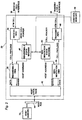
- FIG. 2 illustrates one embodiment of a sub-system generally indicated at 29 and enclosed within a box defined by broken lines for use with the access multiplex 20 shown in Figure 1 for providing a controlled transfer of ATM cell payloads between a line 30 from a receive cell interface and a host memory 32.
- the FIFO 34 constitutes a first-in-first-out memory well known in the art to provide a time buffer.
- the payload in each cell then passes to a reassembly direct memory access (DMA) stage 36.
- DMA direct memory access
- the header in each cell passes to a reassembly state machine 40 for processing.
- the header in each cell is introduced from the reassembly state machine 40 to a control memory 38 which processes the header to provide addresses that indicate where the cell payloads are to be stored in the host memory 32.
- the addresses are then applied through the reassembly state machine 40 to the reassembly direct memory access (DMA) stage 36 to direct the payload from the FIFO 34 through a host interface 42 to a host bus 44.
- the cells are then transferred in the host memory 32 to the addresses indicated by the control memory 38.
- DMA direct memory access
- Cells may also be transferred to a transmit cell interface through a line 45 by the sub-system 29 shown in Figure 2.
- the segmentation state machine 50 reads addresses from the control memory 38 that indicate where cell payloads are stored in the host memory 32. The addresses are then applied by the segmentation state machine 50 to the segmentation direct memory access (DMA) 46 to direct the cell payloads to the transmit FIFO 48.
- the transmit FIFO 48 may be constructed in a manner similar to the receiver FIFO 34.
- the header is introduced by the control memory 38 to the segmentation state machine 50 for combination in the transmit FIFO 48 with the payload.
- the recombined cell then passes to the transmit cell interface line 45.
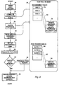
- Figure 3 illustrates in additional detail the operation of the sub-system shown in Figure 2 in separating the header and the payload in a cell, reassembling the cell payloads and recording the reassembled payloads in the host memory 32.
- the cell header is initially read as at 70.
- the header is used to compute a "connection index" (see block 72) to yield a memory address in a reassembly state.
- This is indicated as a table 73 designated as "Reassembly State" in the control memory 38.
- the table 73 contains a plurality of virtual channel connections which are respectively designated as "VCC 1", “VCC 2", “VCC 3", etc.
- Each of the virtual channel connections contains a table 75 which provides certain information including the address of a region of the host memory 38, the length of the region in the host memory and the protocol information for the virtual channel connection VCC.
- Figure 3 schematically shows that the table containing the address region in the host memory 38, the length of the region and the protocol information for the virtual channel connection VCC are being selected from the virtual channel connection designated as "VCC 2". This is indicated by broken lines at 74 and by the table 75 in Figure 3. It will be appreciated that this is schematic and illustrative and that other VCC's may be selected.
- the cell from the line 30 in Figure 2 relating to the receive cell interface is then checked with the protocol information in the VCC 2 virtual channel connection in the table 75 in the control memory 38 as indicated at 76 in Figure 3. If the check indicates that the protocol information in the header and the payload is correct, the region address in the host memory 32 and the length of such region are read from the VCC 2 block in the control memory 38 as indicated at 78 in Figure 3. The region address in the host memory 32 is passed to the reassembly DMA 36 in Figure 2 as indicated at 80. The reassembly DMA 36 is then activated to transfer the cell payload from the receive FIFO 34 in Figure 2 to the host memory 32 as indicated at 82 in Figure 3.
- a "Yes" indication is provided from the block 84.
- This block is designated as "Read Free Region”.
- the control memory 38 contains a Free Region Queue indicated at 90 in Figure 3.
- the block 88 When the block 88 is activated, it causes the next entry in the Free Region Queue 90 to be selected. For example, when entry 1 in the free region queue has been previously selected, entry 2 in the Free Region Queue 90 is now selected. This is indicated by broken lines 92 extending from the entry 2 in the Free Region Queue 90 to a table 94 in Figure 3.
- Entry 2 in the Free Region Queue contains a new address region in the host memory 38 and the length of such region. This information is transferred to the table 75 in place of the information previously recorded in the table.
- the blocks 78, 80, 82, 84, 86 and 88 are now operated as discussed above to transfer the payloads in the cells on the line 30 to the regions in the host memory 32.
- entry 3 in the Free Region Queue may be selected to provide a new address region in the host memory 32 and the length of such region if the payload has not been completely recorded in the host memory 32. The steps described above are repeated in this manner until all of the payload has been recorded in the host memory 32.
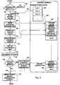
- Figure 4 indicates in additional detail the operation of the sub-system shown in Figure 2 in transferring the cell payloads from the host memory 32, reading the header from the control memory 38 to indicate the ATM path, combining the header and the payload into a cell and transferring the cell to the line 45.
- a block 100 is provided to determine if a VCC cell has been scheduled for a particular time slot. If a cell has not been scheduled, an idle cell (i.e. no cell recorded in a time slot) is transferred to the line 45 in Figure 2. This is indicated by a line 101 in Figure 4.
- the block 100 in Figure 4 selects a virtual channel connection in a table 102 in the control memory 38.
- This table is designated as "Segmentation State" in Figure 4.
- the table 102 contains a plurality of virtual channel connections which are illustratively designated as "VCC 1", “VCC 2", “VCC 3", etc.
- the virtual channel connection VCC 2 is illustratively shown as being selected in the table 102. This is indicated by broken lines 104. It will be appreciated that any other block could have been chosen.
- the virtual channel connection VCC 2 illustratively includes a header value (to indicate the path of transfer of the cell), a region address, a region length, protocol information and the position of the next region description in the host memory. This is illustrated at 106 in Figure 2.
- the header value and the protocol information in the VCC 2 block are read from the control memory 38 as indicated at 108 and 109 respectively in Figure 4.
- the header value is then transferred to the transmit FIFO 48 in Figure 2 as indicated at 110 in Figure 4 and the region address and length are read from the VCC 2 virtual channel connection as indicated at 112 in Figure 4.
- the segmentation DMA 46 in Figure 2 is then set up (see block 114 in Figure 4) and the payload is transferred from the host memory region to the transmit FIFO 48 in Figure 2 (see block 116 in Figure 4).
- a check is made in each transfer of the payload of successive cell to determine if the region being transferred for the virtual channel connection 106 is at the end of its length. This is indicated at 118 in Figure 4.
- the region address at 106 in the control memory is incremented to account for the successive payload transferred to the transmit FIFO 48 and the region length is decremented by the same amount (see block 122). This provides an updated record of the region being processed in the virtual channel connection VCC 2 and an updated record of the remaining length of the region to be processed in the virtual channel connection VCC 2.
- next region is indicated as "Next” in the table 106 and is indicated in additional detail by a table 128 in Figure 4.
- the table 128 is designated as a "Region Descriptor" to conform to the designation in the block 124.
- the table 128 also contains a block designated as "Next”. The table 128 is then transferred to the position of the table 106 to replace the information previously in the table 106.
- the address information transferred from the table 128 to the table 106 is then processed in the blocks 108, 109, 110, 112, 114, 116, 118, 120, 122 and 124 in the same manner as described above.
- the "Next" block in the table 106 is processed to determine the subsequent host address region in the host memory 32 and the length of this address region.
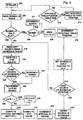
- Figure 5 schematically illustrates a flow chart involving a system for, and method of, scheduling cells from different sources (e.g. telephones such as the telephones 12 and 14 in Figure 1) for transfer in successive time slots in accordance with an individual rate for each of such different sources.
- sources e.g. telephones such as the telephones 12 and 14 in Figure 1.
- the parameters of the system and method are initialized. This is illustrated at 200 in Figure 5.
- Initialization includes the following steps:
- the transfer of cells from a source according to its position in the schedule table is scheduled ahead of the time that such position is presented in the schedule table.
- the current schedule table position is read as indicated at 202 in Figure 5. It may sometimes happen that no cell is scheduled to be transferred at a particular position in the schedule table. This preferably occurs at times during the transfer sequence because the number of time slots during the transfer sequence should exceed the number of cells to be transferred from the different sources during such transfer sequence. In this way, all of the cells from the different sources will be almost certainly transferred in such transfer sequence.
- the schedule table is late (or behind) relative to the intended time slots and there is an idle time slot as discussed above, the value of the "behind" state is decremented and no idle cell is transferred. This is indicated at 211 in Figure 4.
- the schedule table is advanced to the next position as above as indicated at 210.
- the schedule table has a limited number of positions. When an advance or incrementation has been made to the last position in the schedule table, the schedule table is returned to its initial position and a new advance is then made through the successive positions in the schedule table. A determination is made at 212 as to whether the last position in the schedule table has been reached. If the answer is no, the schedule table is read as indicated at 202 and as described above. If the answer is yes, the schedule table is returned to the first position (see block 214) and the schedule table is read as indicated at 202.
- the next source is read from the schedule table. This is the source scheduled to provide a cell at that position in the schedule table. The reading of the next source from the schedule table is indicated at 216 in Figure 5. This cell is transferred to the time slot corresponding to such position as indicated at 218 in Figure 5.
- cells from more than one (1) source may be scheduled for a particular position in the schedule table in accordance with the rates of transfer of cells from such different sources. Only the cell from one (1) source can be transferred into the time slot corresponding to such particular schedule position. The cells from the other sources scheduled at that particular table position are then delayed to subsequent time slots. This delay may occur for each of the different sources scheduled for the same schedule position in any different number of priorities which are well known in the art for other purposes than the purposes of this invention. For example, a simple priority may be on the basis of the relative times at which the sources have scheduled cells for the same position in the schedule table.
- the value of the behind state is incremented. This process is indicated at 222 and 224. If the schedule table is behind when a source has transferred a cell, the late value for the source is incremented in the number of time slots that the schedule table is behind as indicated at 220 in Figure 5.
- the interval value computed at 230 may not be an integral number.
- the value used to schedule the source (the "schedule interval") into the schedule table will be the interval value computed at 230 and increased to the nearest integral number of cell slots.
- the "schedule value” will also be increased to a value of one (1) if less than zero as a source cannot be scheduled into the past.
- the new "late” value for the source is the "schedule interval" minus the desired interval computed in 230.
- schedule table positions may not generate a transmit time slot as indicated by 211 and 210.
- the "schedule interval" is incremented by the number of time slots that the schedule table is behind to account for this possibility as indicated at 232.
- the source is inserted into the schedule table at a time slot in accordance with the "schedule interval" in the discussion above. (See block 234 in Figure 5). A determination is then made as to whether such insertion has occurred from the last source scheduled at the current position in the schedule table. This is indicated at block 236 in Figure 5. If the answer is no, the next source scheduled at the schedule table is read as indicated at 216 in Figure 5. This source is then processed through the blocks 218-234 (even numbers only) in the manner described above. If the answer is yes, the position at the schedule table is set to idle as indicated at 238 in Figure 5 and the position at the schedule table is incremented as indicated at 210 in Figure 5.
- This invention provides certain advantages over the prior art. It separates the header and the payload in each cell, processes the header and reassembles the payload directly to the host memory 32 in Figure 2. This provides a faster response time than in the prior art since only the header in each cell has to be processed and no time is lost in processing the payload in such cell as in the prior art. This saving in time can be significant since the payload in each cell is considerably longer than the header in such cell.
- the invention is also advantageous in providing a control memory for processing the header. Since only the header is processed in the control memory 38, the control memory can be considerably smaller, and can be significantly less costly, than in the prior art since, in the prior art, the control memory has had to have sufficient capacity and speed to process the header and the payload.
- the control memory 38 processes the header to identify information relating to the region in the host memory 32 where the payload is to be stored.
- the headers are read from the control memory 38 to provide an ATM address. This header can then be combined with the payload and the cell containing the combined header and payload can be transferred to the line 45.
- the invention also has other advantages. It schedules cells at successive positions in a schedule table in advance of the time when such cells are to be transferred to time slots from such successive positions in the schedule table. By scheduling such cells in advance of the transfer of the cells to the time slots, no time is lost as in the prior art in determining where and when to transfer each cell after the transfer of the previous cell in the sequence.
- the scheduling discussed in the previous paragraph also has other advantages.
- the invention provides for the transfer of one (1) of the cells to the time slot corresponding to the scheduled position.
- the invention then provides for the sequential transfer, to subsequent time slots which would otherwise be idle, of the other cells scheduled at the particular table position.
- the invention also determines at each instant the number of time slots in which the transfer of cells from each source is late.
- the invention additionally provides for the transfer of cells, from sources in which the cells are late, into otherwise idle time slots to reduce thereafter the number of time slots in which the cells from such source are late. In this way, the invention is able to provide an efficient operation in transferring cells from a number of different sources into successive time slots at different rates.
- the invention In providing additional transfers of cells that are late, the invention also limits the number of cells that can be transferred as "late”. This will prevent the sources from violating certain important traffic parameters in ATM networks.
Abstract
Description
- This invention relates to telecommunications systems for, and methods of, transferring information through telephone lines. More particularly, this invention relates to systems for, and methods of, transferring information such as digitally encoded television and voice signals efficiently and reliably through telephone lines.
- Telephone systems in the United States provide central offices for receiving signals from calling telephones within a particular radius such as one (1) to two (2) miles from the central office and for transmitting telephone signals to such telephones. The telephone signals from a calling telephone are then transmitted through long distances from such central office. The telephone signals then pass to the receiving telephone through a central office within a radius of one (1) mile to two (2) miles from such central office.
- The telephone signals are transmitted long distance between central offices through optical fibers which have replaced other media previously provided for such purposes. The optical fibers have certain distinctive advantages over the lines previously provided. They allow a significantly increased number of signals from different telephones to be transmitted at the same time through the optical fibers. They pass the digitally-encoded signals with a higher accuracy than other media.
- Various systems have been adopted to carry digitally-encoded signals for telephone, video, and data services. One of such systems now being adopted is designated as asynchronous transfer mode (ATM). This system is advantageous because it recognizes that generally signals travel in only one direction at any one time between a calling subscriber and a receiving subscriber. The system preserves bandwidth in the other direction so that a maximum number of different messages can be transmitted in such direction.
- In ATM systems, cells are provided to transmit information between access multiplexers or terminals through central offices. Each of the cells contains headers identifying the calling and receiving stations and also contains a payload providing the information being transmitted and received. The cells pass from the calling telephone through the access multiplexers to a first central station. The cells then pass through the first central station and optical fibers to a second central station and then to the receiving access multiplexer. During the transfer of the cells to the central stations, the headers may be changed. These changes in the address indicate the path that the cell is following between each pair of central stations to reach the receiving telephone.
- In the prior art, to reassemble cells into signals at the access multiplex, the header and the payload in each cell have been transferred to a control memory that processes the header to determine what path it came from and thus reassemble the signal based upon this path. This has created certain difficulties. For example, it has required the control memory to be relatively large, particularly since the memory receives the header and the payload. It has also caused the transfer to be slow, particularly since the header and the payload have to be processed and the payload is generally twelve times longer than the header.
- There are other problems in the operation of the ATM systems of the prior art. These problems have resulted from the fact that access lines and central stations receive cells from a number of different sources. Each source may illustratively constitute a different one of the calling stations and may illustratively have a different rate of transferring cells into successive time slots. For example, one source may transfer cells into an access line in every third (3d) time slot and another source may transfer cells into an access line in every fourth (4th) time slot. In the past, a decision has been made after the transfer of a cell in each time slot as to which source, if any, is to transfer a cell into the next time slot. This system has been cumbersome and slow because the transfer has to be interrupted after the transfer of a cell into each time slot while a decision is being made as to the transfer, if any, in the next time slot.
- This invention provides apparatus for, and methods of, overcoming the disadvantages discussed in the previous paragraphs as occurring in an ATM system. The apparatus and method of this invention minimize the time for processing the cells to update the headers as the cells are transferred through the telephone lines between the calling telephone and the receiving telephone. The apparatus and method of this invention also minimize the time for introducing the cells into successive time slots in the lines by scheduling in advance the cells to be provided in the successive time slots in the lines.
- In one embodiment of the invention, a header and a payload in a cell are separated for transfer between a cell interface and a host memory. The header is transferred to a control memory. For transfer to the host memory, the control memory initially provides a host-memory region address and the region length. The payload is recorded in such address region. The control memory also provides a second host-memory region address, and length, when the payload length exceeds the payload length in the first address region. For transfer from the host memory to the cell interface, the control memory provides a host memory region address and the header combines the header and the payload and passes the combination to the cell interface.
- Cells from different sources (i.e. terminals) are scheduled at table positions dependent upon their individual transfer rates. The cells at the scheduled positions are normally transferred in time slots corresponding to such positions. When more than one (1) cell is scheduled at the same position, one (1) cell is transferred on a preset priority basis to the corresponding time slot. The other cells are delayed for transfer subsequently in idle time slots (i.e. no cell normally scheduled) in the same or other priorities.
- The cell delays for each source are accumulated to a maximum preset value. When the cell delays accumulated for a source exceed the normal time spacing between cells from that source, a cell from the source transfers a cell in an idle time slot prior to the normally scheduled time slot to compensate for such delay.
-
- Figure 1 is a schematic block diagram illustrating on a simplified basis the paths for transferring cells of information in an asynchronous transfer mode between a calling station and a receiving station through an access multiplex;
- Figure 2 is a schematic block diagram on a simplified basis of a system included in the system shown in Figure 1 for transferring cell payloads between a cell interface and a host memory while processing the headers of the cells to control changes in the path of such transfer;
- Figure 3 is a schematic block diagram snowing in additional detail the operation of the sub-system shown in Figure 2 when the cell payloads are transferred from the receive cell interface to the host memory;
- Figure 4 is a schematic block diagram showing in additional detail the operation of the sub-system shown in Figure 2 when the cell payloads are transferred from the host memory to the transmit cell interface; and
- Figure 5 is a schematic block diagram showing a sub-system for scheduling in advance a transfer of cell payloads from a plurality of sources to successive positions in a schedule table for subsequent transfer to successive time slots in an order corresponding to the scheduling of the cells in the successive positions in the schedule table.
- Figure 1 illustrates in block form a system generally indicated at 10 and known in the prior art for transferring signals to and from a pair of telephones (or sources) 12 and 14 respectively through
lines common access multiplex 20. The telephone (or source) 12 may illustratively transmit or receive television signals and telephone (voice) signals on aline 16 and the telephone (or source) 14 may illustratively transmit or receive television signals and telephone (voice) signals on aline 18. All signals are digitally encoded. For purposes of simplification, the television signals are shown in Figure 1 as being transferred in solid lines and the telephone signals are shown in Figure 1 as being transferred in broken lines. - The signals in the
lines access multiplex 20. The respective digitally-encoded transmit signals are segmented into fixed-length cell payloads and a cell header is added to each cell payload to form a cell. Similarly, received cells are reassembled into the respective receive signals. The headers of the cells are generated in the access multiplex to provide a virtual channel indication and/or a virtual path indication. The header indicates the path which is being followed to pass the cells to acentral office 22. Thecentral office 22 may modify the header again in the cells to identify the path through which the cells are subsequently being transferred. The cells may then be transferred either to atelevision access 24 or to atelephone access 26 at receiving stations generally indicated at 28 in Figure 1. - Figure 2 illustrates one embodiment of a sub-system generally indicated at 29 and enclosed within a box defined by broken lines for use with the
access multiplex 20 shown in Figure 1 for providing a controlled transfer of ATM cell payloads between aline 30 from a receive cell interface and ahost memory 32. When the cells are transferred from theline 30, the cells pass through a receiveFIFO 34. The FIFO 34 constitutes a first-in-first-out memory well known in the art to provide a time buffer. The payload in each cell then passes to a reassembly direct memory access (DMA) stage 36. The header in each cell passes to areassembly state machine 40 for processing. - The header in each cell is introduced from the
reassembly state machine 40 to acontrol memory 38 which processes the header to provide addresses that indicate where the cell payloads are to be stored in thehost memory 32. The addresses are then applied through thereassembly state machine 40 to the reassembly direct memory access (DMA) stage 36 to direct the payload from theFIFO 34 through ahost interface 42 to ahost bus 44. The cells are then transferred in thehost memory 32 to the addresses indicated by thecontrol memory 38. - Cells may also be transferred to a transmit cell interface through a
line 45 by thesub-system 29 shown in Figure 2. Thesegmentation state machine 50 reads addresses from thecontrol memory 38 that indicate where cell payloads are stored in thehost memory 32. The addresses are then applied by thesegmentation state machine 50 to the segmentation direct memory access (DMA) 46 to direct the cell payloads to the transmitFIFO 48. The transmitFIFO 48 may be constructed in a manner similar to thereceiver FIFO 34. The header is introduced by thecontrol memory 38 to thesegmentation state machine 50 for combination in the transmitFIFO 48 with the payload. The recombined cell then passes to the transmitcell interface line 45. - Figure 3 illustrates in additional detail the operation of the sub-system shown in Figure 2 in separating the header and the payload in a cell, reassembling the cell payloads and recording the reassembled payloads in the
host memory 32. In the flow chart shown in Figure 3, the cell header is initially read as at 70. The header is used to compute a "connection index" (see block 72) to yield a memory address in a reassembly state. This is indicated as a table 73 designated as "Reassembly State" in thecontrol memory 38. The table 73 contains a plurality of virtual channel connections which are respectively designated as "VCC 1", "VCC 2", "VCC 3", etc. - Each of the virtual channel connections contains a table 75 which provides certain information including the address of a region of the
host memory 38, the length of the region in the host memory and the protocol information for the virtual channel connection VCC. Figure 3 schematically shows that the table containing the address region in thehost memory 38, the length of the region and the protocol information for the virtual channel connection VCC are being selected from the virtual channel connection designated as "VCC 2". This is indicated by broken lines at 74 and by the table 75 in Figure 3. It will be appreciated that this is schematic and illustrative and that other VCC's may be selected. - The cell from the
line 30 in Figure 2 relating to the receive cell interface is then checked with the protocol information in theVCC 2 virtual channel connection in the table 75 in thecontrol memory 38 as indicated at 76 in Figure 3. If the check indicates that the protocol information in the header and the payload is correct, the region address in thehost memory 32 and the length of such region are read from theVCC 2 block in thecontrol memory 38 as indicated at 78 in Figure 3. The region address in thehost memory 32 is passed to the reassembly DMA 36 in Figure 2 as indicated at 80. The reassembly DMA 36 is then activated to transfer the cell payload from the receiveFIFO 34 in Figure 2 to thehost memory 32 as indicated at 82 in Figure 3. - As the successive cell payloads for the
VCC 2 table 73 are reassembled in the region, a check is made in each reassembly to determine if the end of the region in theVCC 2 channel connection has been reached. This is indicated at 84 in Figure 3. If the answer is "No", the region address for successive cells is incremented for the successive payloads in theVCC 2 channel connection recorded in the host memory region and the region length is decremented by the same amount. Ablock 86 in Figure 3 indicates this. - If the end of the region in the
VCC 2 table in thecontrol memory 38 has been reached, a "Yes" indication is provided from theblock 84. This causes ablock 88 to be activated in Figure 3. This block is designated as "Read Free Region". Thecontrol memory 38 contains a Free Region Queue indicated at 90 in Figure 3. When theblock 88 is activated, it causes the next entry in theFree Region Queue 90 to be selected. For example, whenentry 1 in the free region queue has been previously selected,entry 2 in theFree Region Queue 90 is now selected. This is indicated bybroken lines 92 extending from theentry 2 in theFree Region Queue 90 to a table 94 in Figure 3. -
Entry 2 in the Free Region Queue contains a new address region in thehost memory 38 and the length of such region. This information is transferred to the table 75 in place of the information previously recorded in the table. Theblocks line 30 to the regions in thehost memory 32. At the end of this region,entry 3 in the Free Region Queue may be selected to provide a new address region in thehost memory 32 and the length of such region if the payload has not been completely recorded in thehost memory 32. The steps described above are repeated in this manner until all of the payload has been recorded in thehost memory 32. - Figure 4 indicates in additional detail the operation of the sub-system shown in Figure 2 in transferring the cell payloads from the
host memory 32, reading the header from thecontrol memory 38 to indicate the ATM path, combining the header and the payload into a cell and transferring the cell to theline 45. In the flow chart shown in Figure 4, ablock 100 is provided to determine if a VCC cell has been scheduled for a particular time slot. If a cell has not been scheduled, an idle cell (i.e. no cell recorded in a time slot) is transferred to theline 45 in Figure 2. This is indicated by aline 101 in Figure 4. - If a cell has been scheduled for the particular time slot, the
block 100 in Figure 4 selects a virtual channel connection in a table 102 in thecontrol memory 38. This table is designated as "Segmentation State" in Figure 4. As shown in Figure 4, the table 102 contains a plurality of virtual channel connections which are illustratively designated as "VCC 1", "VCC 2", "VCC 3", etc. The virtualchannel connection VCC 2 is illustratively shown as being selected in the table 102. This is indicated bybroken lines 104. It will be appreciated that any other block could have been chosen. The virtualchannel connection VCC 2 illustratively includes a header value (to indicate the path of transfer of the cell), a region address, a region length, protocol information and the position of the next region description in the host memory. This is illustrated at 106 in Figure 2. - The header value and the protocol information in the
VCC 2 block are read from thecontrol memory 38 as indicated at 108 and 109 respectively in Figure 4. The header value is then transferred to the transmitFIFO 48 in Figure 2 as indicated at 110 in Figure 4 and the region address and length are read from theVCC 2 virtual channel connection as indicated at 112 in Figure 4. Thesegmentation DMA 46 in Figure 2 is then set up (seeblock 114 in Figure 4) and the payload is transferred from the host memory region to the transmitFIFO 48 in Figure 2 (seeblock 116 in Figure 4). A check is made in each transfer of the payload of successive cell to determine if the region being transferred for thevirtual channel connection 106 is at the end of its length. This is indicated at 118 in Figure 4. - If the end of the host region in the
VCC 2 virtual channel connection has not been reached as indicated at 120 in Figure 4, the region address at 106 in the control memory is incremented to account for the successive payload transferred to the transmitFIFO 48 and the region length is decremented by the same amount (see block 122). This provides an updated record of the region being processed in the virtualchannel connection VCC 2 and an updated record of the remaining length of the region to be processed in the virtualchannel connection VCC 2. - When the end of the region in the virtual
channel connection VCC 2 has been reached, the address of the next region in thehost memory 38 and the length of this region are read as indicated at 124. This next region is indicated as "Next" in the table 106 and is indicated in additional detail by a table 128 in Figure 4. The table 128 is designated as a "Region Descriptor" to conform to the designation in theblock 124. The table 128 also contains a block designated as "Next". The table 128 is then transferred to the position of the table 106 to replace the information previously in the table 106. The address information transferred from the table 128 to the table 106 is then processed in theblocks host memory 32 and the length of this address region. - Figure 5 schematically illustrates a flow chart involving a system for, and method of, scheduling cells from different sources (e.g. telephones such as the
telephones - Initialization includes the following steps:
- 1. The "late" state of each source (or telephone) is set to a value of zero (0) from a time standpoint. This means that none of the sources is initially late in transferring a cell from that source to one of a plurality of time slots.
- 2. A schedule formed from a plurality of successive positions is set to "Idle". This means that there is no source information in any of the positions in the schedule table.
- 3. The rate I of transferring cells from each source to the transmit
cell interface 45 is scheduled at an individual value for each source. For example, a first source may be scheduled to transfer a cell in every third (3rd) position in the schedule table. This means that the rate I for the first source is three (3). Similarly, the rate I for a second source may be set to four (4) to indicate that a cell from that source is scheduled to be transferred to a position in the schedule table once in every four (4) positions. - 5. The parameter L is individually set for each of the different sources. The parameter L for a source indicates the maximum value of the "late" state for that source. A source can be late by a value greater than L relative to the time that a cell from the source should be transferred in a time slot in accordance with the rate I for that source. However, the "late" value for the source is limited to L. For example, the maximum "late" value L for the first source may be twenty (20) time slots and the maximum late value L for the second source may be thirty (30) time slots.
- 6. The position in the schedule table is set to the first entry in that table.
- 7. The "behind" state is set to zero (0). The "behind" state indicates the number of cell slots that the schedule table is late relative to the intended time slots.
- As previously described, the transfer of cells from a source according to its position in the schedule table is scheduled ahead of the time that such position is presented in the schedule table. After the schedule table has been initialized as described above, the current schedule table position is read as indicated at 202 in Figure 5. It may sometimes happen that no cell is scheduled to be transferred at a particular position in the schedule table. This preferably occurs at times during the transfer sequence because the number of time slots during the transfer sequence should exceed the number of cells to be transferred from the different sources during such transfer sequence. In this way, all of the cells from the different sources will be almost certainly transferred in such transfer sequence.
- When a position in the schedule table is idle as determined at 204 and as indicated as "Yes" to the right of the
block 204, a determination is made (see block 206) whether the schedule table is late (or behind) relative to the intended time slots in the schedule table normally scheduled for such sources. If the schedule table is not late (or behind) in scheduling in a particular position in the schedule table and if no cell is normally scheduled at that position, a time slot corresponding to such position is filled with an idle cell. This is indicated at 208 in Figure 5. Even though no cell payload is scheduled to be transferred in the particular position in the schedule table and an idle cell is actually transferred in the corresponding time slot, the schedule table is advanced or incremented to the next position as indicated at 210 in Figure 5. - If the schedule table is late (or behind) relative to the intended time slots and there is an idle time slot as discussed above, the value of the "behind" state is decremented and no idle cell is transferred. This is indicated at 211 in Figure 4. The schedule table is advanced to the next position as above as indicated at 210.
- The schedule table has a limited number of positions. When an advance or incrementation has been made to the last position in the schedule table, the schedule table is returned to its initial position and a new advance is then made through the successive positions in the schedule table. A determination is made at 212 as to whether the last position in the schedule table has been reached. If the answer is no, the schedule table is read as indicated at 202 and as described above. If the answer is yes, the schedule table is returned to the first position (see block 214) and the schedule table is read as indicated at 202.
- When the position being processed in the schedule table is not idle, the next source is read from the schedule table. This is the source scheduled to provide a cell at that position in the schedule table. The reading of the next source from the schedule table is indicated at 216 in Figure 5. This cell is transferred to the time slot corresponding to such position as indicated at 218 in Figure 5.
- It may sometimes happen that cells from more than one (1) source may be scheduled for a particular position in the schedule table in accordance with the rates of transfer of cells from such different sources. Only the cell from one (1) source can be transferred into the time slot corresponding to such particular schedule position. The cells from the other sources scheduled at that particular table position are then delayed to subsequent time slots. This delay may occur for each of the different sources scheduled for the same schedule position in any different number of priorities which are well known in the art for other purposes than the purposes of this invention. For example, a simple priority may be on the basis of the relative times at which the sources have scheduled cells for the same position in the schedule table.
- When a cell from a source is delayed in the manner discussed above to a subsequent time slot, the value of the behind state is incremented. This process is indicated at 222 and 224. If the schedule table is behind when a source has transferred a cell, the late value for the source is incremented in the number of time slots that the schedule table is behind as indicated at 220 in Figure 5.
- Every time that an increment occurs in the number of time slots that the transfer of a cell from a particular source is late or behind, a determination is made as to whether the count has exceeded the maximum value of L for that particular source. This is indicated at 226 in Figure 5. If the maximum value L has been reached for that particular source, the late count for that particular source is maintained at L. (See 228 in Figure 5). If the maximum count L has not been reached for that particular source, an advance is made from the
block 226 to ablock 230. - The
block 230 determines the number of time slots before the next cell for the particular source block would normally be presented. This number is designated as "Interval" in Figure 5. As shown in Figure 5,
- Because the value of I is not necessarily an integral number of cell slots, the interval value computed at 230 may not be an integral number. The value used to schedule the source (the "schedule interval") into the schedule table will be the interval value computed at 230 and increased to the nearest integral number of cell slots. The "schedule value" will also be increased to a value of one (1) if less than zero as a source cannot be scheduled into the past. The new "late" value for the source is the "schedule interval" minus the desired interval computed in 230. These computations are indicated at 231.
- If the schedule table is "behind" relative to the intended time slots, then future schedule table positions may not generate a transmit time slot as indicated by 211 and 210. The "schedule interval" is incremented by the number of time slots that the schedule table is behind to account for this possibility as indicated at 232.
- The source is inserted into the schedule table at a time slot in accordance with the "schedule interval" in the discussion above. (See
block 234 in Figure 5). A determination is then made as to whether such insertion has occurred from the last source scheduled at the current position in the schedule table. This is indicated atblock 236 in Figure 5. If the answer is no, the next source scheduled at the schedule table is read as indicated at 216 in Figure 5. This source is then processed through the blocks 218-234 (even numbers only) in the manner described above. If the answer is yes, the position at the schedule table is set to idle as indicated at 238 in Figure 5 and the position at the schedule table is incremented as indicated at 210 in Figure 5. - This invention provides certain advantages over the prior art. It separates the header and the payload in each cell, processes the header and reassembles the payload directly to the
host memory 32 in Figure 2. This provides a faster response time than in the prior art since only the header in each cell has to be processed and no time is lost in processing the payload in such cell as in the prior art. This saving in time can be significant since the payload in each cell is considerably longer than the header in such cell. - The invention is also advantageous in providing a control memory for processing the header. Since only the header is processed in the
control memory 38, the control memory can be considerably smaller, and can be significantly less costly, than in the prior art since, in the prior art, the control memory has had to have sufficient capacity and speed to process the header and the payload. - When the cells are being transferred through the
line 30 from the receive cell interface to thehost memory 32, thecontrol memory 38 processes the header to identify information relating to the region in thehost memory 32 where the payload is to be stored. When the cells are being transferred from thehost memory 32 to the transmit cell interface, the headers are read from thecontrol memory 38 to provide an ATM address. This header can then be combined with the payload and the cell containing the combined header and payload can be transferred to theline 45. - The invention also has other advantages. It schedules cells at successive positions in a schedule table in advance of the time when such cells are to be transferred to time slots from such successive positions in the schedule table. By scheduling such cells in advance of the transfer of the cells to the time slots, no time is lost as in the prior art in determining where and when to transfer each cell after the transfer of the previous cell in the sequence.
- The scheduling discussed in the previous paragraph also has other advantages. When cells from more than one (1) source are scheduled at a particular position in the schedule table, the invention provides for the transfer of one (1) of the cells to the time slot corresponding to the scheduled position. The invention then provides for the sequential transfer, to subsequent time slots which would otherwise be idle, of the other cells scheduled at the particular table position.
- The invention also determines at each instant the number of time slots in which the transfer of cells from each source is late. The invention additionally provides for the transfer of cells, from sources in which the cells are late, into otherwise idle time slots to reduce thereafter the number of time slots in which the cells from such source are late. In this way, the invention is able to provide an efficient operation in transferring cells from a number of different sources into successive time slots at different rates.
- In providing additional transfers of cells that are late, the invention also limits the number of cells that can be transferred as "late". This will prevent the sources from violating certain important traffic parameters in ATM networks.
- Although this invention has been disclosed and illustrated with reference to particular embodiments, the principles involved are susceptible for use in numerous other embodiments which will be apparent to persons skilled in the art. The invention is, therefore, to be limited only as indicated by the scope of the appended claims.
Claims (46)
- In combination for transferring in an asynchronous transfer mode a cell which has a header providing addresses and has a payload providing data,
host memory means,
first means for receiving the cell,
second means for transferring the header in the cell,
third means for transferring the payload in the cell,
control memory means responsive to the header transferred by the second means for selecting the address region in the host memory means for recording the payload in the host memory means, and
fourth means responsive to the address region selected in the host memory means by the control memory means and to the payload from the second means for transferring the payload in the cell to the selected address region in the host memory means. - In a combination as set forth in claim 1,
the payload being longer than the selected address region in the host memory means,
fifth means for indicating the selected address region in the host memory means,
sixth means for determining, upon each transfer of the payload in the cell to the selected address region in the host memory, if such transfer has reached the end of such selected addresses region, and
seventh means responsive to the transfer of the payload to the end of the selected address region in the host memory means for providing for the selection of a different address region in the host memory means for the recording of the payload in the host memory means. - In a combination as set forth in claim 1, eighth means for updating the region address in the control memory means upon each transfer of the payload in the cell by the fourth means to the host memory means.
- In a combination as set forth in claim 2, eighth means for updating the region address in the control memory means upon each transfer of the payload in the cell by the fourth means to the host memory means.
- In combination for providing in an asynchronous transfer mode a cell which has a header providing addresses and has a payload providing data,
host memory means,
cell interface means,
first means for providing the cell at one of the host memory means and the cell interface means,
second means responsive to the cell for separating the payload in the cell and the header in the cell,
control memory means responsive to the header in the cell for modifying the header in the cell to provide for the transfer of the cell between a particular address region in the host memory means and the cell interface means, and
third means for transferring the payload in the cell between the particular address region in the host memory means and the cell interface means in accordance with the modification of the header in the cell by the control memory means. - In a combination as set forth in claim 5,
the particular address region in the host memory means being less than the length of the payload in the cell,
fourth means for determining at each instant whether the transfer of the payload in the cell between the particular address region in the host memory means and the cell interface means is at the end of address in the host memory means, and
the control means being responsive to the transfer of the payload in the cell between the particular address region in the host memory means and the cell interface means for selecting a second particular address region in the host memory means for the transfer of the payload in the cell between the host memory means and the cell interface means. - In a combination as set forth in claim 5,
register means disposed between the second means and the cell interface means for providing a time buffer between the second means and the cell interface means. - In a combination as set forth in claim 5,
register means disposed between the third means and the cell interface means for providing a time buffer between the third means and the cell interface means. - In combination for providing in an asynchronous transfer mode a cell having a header providing addresses and having a payload providing data,
host memory means,
cell interface means,
first means for providing the cell from one of the host memory means and the cell interface means,
a state machine for separating the header and the payload in the cell,
control memory means responsive to the header from the state machine for modifying the header in accordance with the direction of the transfer of the cell between the host memory means and the cell interface means, and
third means responsive to the modified header from the control memory means for transferring the payload to the other one of the host memory means and the framer interface means in accordance with the header. - In a combination as set forth in claim 9,
the control memory means indicating a first address region in the host memory means,
the address region in the host memory means having a length less than the length of the payload, and
fourth means for indicating if the end of the first address region is in the host memory means has been reached upon each transfer of the payload between the first region address in the host memory means and the cell interface means,
the control memory means being operative to indicate a second address region in the host memory means when the transfer of the payload between the first address region in the host memory means and the cell interface means has reached the end of the first address region in the host memory means. - In a combination as set forth in claim 9,
fourth means for providing a timing buffer between the host memory means and the cell interface means. - In a combination as set forth in claim 9,
the control memory means being operative to include the address region of the host memory means in the header when the payload in the cell is being transferred from the cell interface means to the host memory means. - In a combination as set forth in claim 9,
the control memory means being operative to include the asynchronous transfer mode address of the cell in the header when the payload is being transferred from the host memory means to the cell interface means. - In combination for providing in an asynchronous transfer mode a cell which has a header providing addresses and has a payload providing data,
host memory means,
cell interface means,
first means for providing the cell at the cell interface means,
a state machine for separating the header and the payload in the cell,
control memory means responsive to the header in the cell from the state machine for modifying the header to indicate the address region in which the payload is to be recorded in the host memory means, and
second means for transferring the payload to the address region in the host memory means in accordance with the modified header. - In a combination as set forth in claim 14,
the control memory means indicating a first address region in the host memory means,
the length of the first address region in the host memory means being less than the length of the payload, and
third means for indicating if the end of the first address region in the host memory means has been reached upon each transfer of the payload to the first address region in the host memory means, and
the control memory means being operative to indicate a second address region in the host memory means for the transfer of the payload upon the transfer of the payload to the end of the first address region in the host memory means. - In a combination as set forth in claim 15,
fourth means for providing a timing buffer between the host memory means and the cell interface means. - In a method of providing in an asynchronous transfer mode a cell having a header providing addresses and having a payload providing data, the steps of:
providing a cell interface,
providing a host memory,
providing the cell in an individual one of the cell interface and the host memory for transfer to the other one or the cell interface and the host memory,
separating the header and the payload in the cell,
providing a control memory,
modifying the header in the control memory in accordance with the direction of transfer of the cell between the cell interface and the host memory, and
transferring the payload into the individual one of the cell interface and the host memory in accordance with the modified header. - In a method as set forth in claim 17 wherein
the host memory has a first address region and wherein
the host memory indicates upon each transfer of the payload between the cell interface and first region in the host memory whether the transfer has been made to the end of the address region in the host memory and wherein
the host memory has a second address region and wherein
the control memory modifies the header in accordance with the second address region in the host memory after the transfer has been made to the end of the first address region in the host memory. - In a method as set forth in claim 17 wherein
the transfer of the payload between the cell interface and the host memory is buffered in time. - In a method as set forth in claim 17 wherein
a determination is made upon each transfer of the payload to the individual one of the cell interface and the host memory as to whether the transfer has been made to the end of the first address region, and
wherein a transfer is then made of the payload in the first address region in the host memory when the transfer has not been made in all of the first address region in the host memory and wherein
the transfer is then made of the payload in the second address region in the host memory when the transfer has been made to the end of the first address region. - In a method of transferring cells to successive time slots from a plurality of sources each operative to provide cells at an individual rate for such transfer, the steps of:
determining the individual rate of transfer from each of the sources in the plurality,
providing a schedule table with successive positions,
scheduling each of the sources in the plurality to provide cells at the different positions in the schedule table in accordance with the individual rate determined for the transfer of the cells from such sources,
determining the number of positions in the schedule table that each source is late in transferring cells to the time slots as a result of a conflict in the scheduling of the cells from more than one source in the plurality at individual ones of the different positions in the schedule table, and
scheduling the sources to provide cells in the idle positions in the schedule table when such sources are late in transferring cells in the time slots. - In a method as set forth in claim 21 wherein
the sources provided in the same position in the schedule table are transferred into different time slots. - In a method as set forth in claim 21 wherein
one of a plurality of cells scheduled for transfer to the same position in the schedule table is transferred at the time slot corresponding to such scheduled position and wherein
the other sources scheduled for transferring cells from the same position in the schedule table are transferred into time slots which are after the time slot corresponding to the scheduled position and which are otherwise idle. - In a method as set forth in claim 22 wherein
the sources in the plurality transfer cells into the different time slots in accordance with the relative times at which such sources schedule such cells at such position. - In a method as set forth in claim 23 wherein
the different sources scheduled for transferring cells from the same position in the schedule table are transferred into otherwise idle time slots in an order related to the relative times at which such source scheduled cells for transfer at the same position in the schedule table. - In a method of transferring cells from a plurality of sources each operative to provide cells at an individual rate for such transfer, the steps of:
providing a schedule table having a plurality of positions for receiving the cells from the different sources in the plurality,
providing a sequence of time slots for transferring the cells at the different positions in the schedule table,
determining the rate of transfer of the cells from each of the different sources in the plurality,
providing the cells from each of the different sources in the plurality at the different positions determined for such cells in the schedule table in accordance with the transfer rate determined for such source,
transferring the cells at the successive time slots in the sequence in accordance with the positioning of the different cells at the successive positions in the schedule table, and
providing a delayed transfer, in slots not otherwise receiving cells, of cells from individual ones of the sources in the plurality when such cells are at the same position in the schedule table with cells from other ones of the sources in the plurality. - In a method as set forth in claim 26 wherein
a schedule is made in positions in the schedule table ahead of the time for the transfer of the cells at such positions to determine the relative times for the transfer of the cells at such positions in the successive time slots. - In a method as set forth in claim 26 wherein
idle time slots are provided where no cells would otherwise be transferred and wherein
cells in positions receiving a plurality of cells in the schedule table and not transferred in the time slots otherwise scheduled for such cells are transferred in such idle time slots after such otherwise scheduled time slots. - In a method as set forth in claim 26 wherein
the number of time slots from each of the sources after the time slot normally provided for the transfer of a cell from such source is determined in each time slot for such source and wherein
the cell from each such source is transferred when the number of time slots from such normally provided time slot for such source is at least as great as the number normally provided between successive ones of the cells from such source. - In a method of transferring cells from a plurality of sources each operative to provide cells at an individual rate for such transfer, the steps of:
providing a plurality of positions in a schedule table,
scheduling cells in successive ones of the positions in the schedule table from each individual one of the sources in the plurality in accordance with the rate scheduled for the cells from such source,
providing a plurality of successive time slots,
transferring the cell in each of the successive positions in the schedule table at the time slot corresponding to such successive position when there is only one cell at each of such successive positions, and
scheduling a delay in the time slot for each of individual ones of the sources in the plurality when the cells from such individual ones of the sources are scheduled in the same position in the schedule table as the cell for a particular one of the sources in the plurality. - In a method as set forth in claim 30 wherein
the delayed cells from the individual ones of the sources in the plurality are scheduled at a position in the schedule table for transfer when no cell from any of the sources in the plurality is otherwise scheduled in such position for transfer. - In a method as set forth in claim 30 wherein
a cell from a source is scheduled for transfer in a particular time slot after the time slot normally scheduled for the transfer of such cell when such particular time slot would not otherwise receive a cell from any of the sources in the plurality. - In a method as set forth in claim 30 wherein
the schedule table is provided with a limited number of successive positions and wherein
a determination is made in each scheduling of a cell in one of the positions in the schedule table whether the scheduling is at the last position in the schedule table and wherein
the schedule table is advanced to the next position in the schedule table when the scheduling is not at the last position in the schedule table and wherein
the schedule table is set to the first position when the scheduling is at the last position in the schedule table. - In a method as set forth in claim 30 wherein
each source has a value indicating the number of time slots that such source is late in transferring a cell into one of the time slots and wherein
the late value for such source is incremented in the number of time slots that the schedule table is behind if the schedule table is behind when such source has transferred a cell to the schedule table. - In a method of transferring cells from a plurality of sources each operative to provide cells at an individual rate for such transfer, the steps of:
providing a plurality of positions in a schedule table,
scheduling the cells from individual ones of the sources in successive ones of the positions in the schedule table in accordance with the rate scheduled for the cells in such sources,
providing a plurality of successive time slots,
transferring the cell in each of the successive positions in the schedule table to the time slot corresponding to such successive position in the schedule table when there is only one cell scheduled at such successive position,
transferring the cell from a particular one of the sources in the plurality to the time slot corresponding to a position in the table when this cell and cells from other sources in the plurality are scheduled at such position in the table,
scheduling a delay in the time slot from each of the other sources in the plurality when the cell from such other sources are scheduled in the same position in the schedule table as the cell from the particular one of the sources in the plurality,
accumulating the delays in the time slots for each of the sources in the plurality, and
providing a delayed transfer of the cells from each of the other sources to the time slots not otherwise receiving a cell from the sources in the plurality when there is an accumulated delay for such source of a number of time slots greater than the number represented by the normal rate of transferring successive cells from such source. - In a method as set forth in claim 35 wherein
a number corresponding to the number of time slots normally between successive cells in each source is subtracted from the accumulated delay for such source when a cell from such source is transferred on the delayed basis. - In a method as set forth in claim 35 wherein
the schedule table is provided with a limited number of successive positions and wherein
a determination is made in each scheduling of a cell in one of the positions in the schedule table whether the scheduling is at the last position in the schedule table and wherein
the schedule table is advanced to the next position in the schedule table when the scheduling is not at the last position in the schedule table and wherein
the schedule table is set to the first position when the scheduling is at the last position in the schedule table. - In a method as set forth in claim 37 wherein
the schedule table is advanced from one position In the schedule table to the next position in the schedule table when the schedule table is idle at the one position. - In a method as set forth in claim 35 wherein
there are a limited number of successive positions in the schedule table and wherein
there is a sequential advance in the scheduling of the such positions in the schedule table and wherein
the scheduling is advanced from the last position in the table to the first position in the schedule table every time that the scheduling has advanced to the last position in the schedule table. - In a method of transferring cells, the steps of:
providing a plurality of sources each operative to provide cells at an individual rate for such transfer,
providing a schedule table having a plurality of positions,
scheduling the cells from the different sources in the plurality at the different positions in the schedule table in accordance with the individual rates of transfer of cells from such sources,
transferring the cells at the scheduled positions in the schedule table to successive time slots in the order scheduled for such cells at the successive positions in the schedule table,
the table having a limited number of successive positions for scheduling, and
advancing the table from the last position in the schedule table to the first position in the schedule table when the scheduling of cells has been provided at the last position in the schedule table. - In a method as set forth in claim 40, the step of:
advancing through a time slot without transferring a cell from one of the sources in the plurality to such time slot when no cell has been scheduled in the position in the schedule table corresponding to such time slot. - In a method as set forth in claim 41, the step of:
delaying a cell scheduled at a particular position in the schedule table from an individual one of the sources in the plurality when that cell and the cell from another one of the sources in the plurality have been scheduled at the particular position in the schedule table and when the cell from such other one of the sources in the plurality has been transferred to the time slot corresponding to the particular position in the table. - In a method as set forth in claim 42, the steps of:
each source has a value indicating the number of time slots that such source is late in transferring a cell into one of the time slots and wherein
the late value for such source is incremented in the number of time slots that the schedule table is behind if the schedule table is behind when such source has transferred a cell to the schedule table. - In a method of transferring cells, the steps of
providing a plurality of sources each operative to provide cells at an individual rate for such transfer,
providing a schedule table having a plurality of successive positions,
scheduling the cells from the different sources in the plurality at the different positions in the schedule table in accordance with the individual rate of transfer of cells for each of such sources,
transferring the cells at the scheduled positions in the table to successive time slots in the order scheduled for such cells at the successive positions in the table, and
advancing through a particular time slot without transferring a cell from one of the sources in the plurality when no cell has been scheduled at the position in the schedule table corresponding to such particular time slot. - In a method as set forth in claim 44 wherein
cells from different sources in the plurality are scheduled at a particular position in the schedule table in accordance with the individual rates for the cells from such sources and wherein
the cell from one of such different sources is transferred at the time slot corresponding to such particular position in the table and wherein
the cells from the other ones of the different sources are transferred at delayed from the time slot receiving the transfer of a cell from such one time slot and time slots where no cell would otherwise be transferred. - In a method as set forth in claim 44 wherein
the schedule table is provided with a limited number of successive positions and wherein
a determination is made in each scheduling of a cell in one of the positions in the schedule table whether the scheduling is at the last position in the schedule table and wherein
the schedule table is advanced to the next position in the schedule table when the scheduling is not at the last position in the schedule table and wherein
the schedule table is set to the first position when the scheduling is at the last position in the schedule table.
Applications Claiming Priority (2)
| Application Number | Priority Date | Filing Date | Title |
|---|---|---|---|
| US29906894A | 1994-08-31 | 1994-08-31 | |
| US299068 | 1999-04-23 |
Publications (3)
| Publication Number | Publication Date |
|---|---|
| EP0703718A2 true EP0703718A2 (en) | 1996-03-27 |
| EP0703718A3 EP0703718A3 (en) | 1998-12-16 |
| EP0703718B1 EP0703718B1 (en) | 2003-02-12 |
Family
ID=23153189
Family Applications (1)
| Application Number | Title | Priority Date | Filing Date |
|---|---|---|---|
| EP95113719A Expired - Lifetime EP0703718B1 (en) | 1994-08-31 | 1995-08-31 | Controller for ATM segmentation and reassembly |
Country Status (5)
| Country | Link |
|---|---|
| US (2) | US5949781A (en) |
| EP (1) | EP0703718B1 (en) |
| JP (1) | JPH08195758A (en) |
| CA (1) | CA2156771C (en) |
| DE (1) | DE69529593T2 (en) |
Cited By (3)
| Publication number | Priority date | Publication date | Assignee | Title |
|---|---|---|---|---|
| EP0814631A1 (en) * | 1996-06-19 | 1997-12-29 | Motorola, Inc. | An ATM line card and method for transferring connection memory data |
| EP0845918A2 (en) * | 1996-11-27 | 1998-06-03 | Rockwell Semiconductor Systems | System for, and method of, ATM segmentation and re-assembly of cells providing streaming data |
| GB2324676A (en) * | 1997-04-23 | 1998-10-28 | Fujitsu Ltd | Interfacing to SAR devices in ATM switching apparatus |
Families Citing this family (23)
| Publication number | Priority date | Publication date | Assignee | Title |
|---|---|---|---|---|
| US5845153A (en) * | 1995-07-07 | 1998-12-01 | Integrated Device Technology, Inc. | Memory interface for asynchronous transfer mode segmentation and reassembly circuit |
| US6034945A (en) | 1996-05-15 | 2000-03-07 | Cisco Technology, Inc. | Method and apparatus for per traffic flow buffer management |
| JP2760343B2 (en) * | 1996-05-31 | 1998-05-28 | 日本電気株式会社 | ATM cell circuit |
| US6075790A (en) * | 1996-12-11 | 2000-06-13 | Brooktree Corporation | Asynchronous transfer mode system for, and method of, writing a cell payload between a control queue on one side of a system bus and a status queue on the other side of the system bus |
| US6097734A (en) * | 1997-04-30 | 2000-08-01 | Adaptec, Inc. | Programmable reassembly of data received in an ATM network |
| US6201813B1 (en) | 1997-06-30 | 2001-03-13 | Cisco Technology, Inc. | Method and apparatus for using ATM queues for segmentation and reassembly of data frames |
| US6487202B1 (en) | 1997-06-30 | 2002-11-26 | Cisco Technology, Inc. | Method and apparatus for maximizing memory throughput |
| US6430191B1 (en) | 1997-06-30 | 2002-08-06 | Cisco Technology, Inc. | Multi-stage queuing discipline |
| US6026090A (en) * | 1997-11-14 | 2000-02-15 | Fore System, Inc. | Method and system for receiving ATM cells from an ATM network by a host |
| US6128300A (en) * | 1997-12-03 | 2000-10-03 | Nokia High Speed Access Products Inc. | Line card with modem interace |
| US6526060B1 (en) | 1997-12-05 | 2003-02-25 | Cisco Technology, Inc. | Dynamic rate-based, weighted fair scheduler with explicit rate feedback option |
| GB2332333B (en) * | 1997-12-09 | 2003-01-15 | Sony Uk Ltd | An ATM re-assembly circuit and method |
| US6631484B1 (en) * | 1998-03-31 | 2003-10-07 | Lsi Logic Corporation | System for packet communication where received packet is stored either in a FIFO or in buffer storage based on size of received packet |
| GB9821768D0 (en) * | 1998-10-06 | 1998-12-02 | Sgs Thomson Microelectronics | Data transfer |
| US6614794B1 (en) | 1999-03-03 | 2003-09-02 | Conexant Systems, Inc. | System and method for multiple modem traffic redirection |
| US6639915B1 (en) * | 1999-04-07 | 2003-10-28 | Utstarcom, Inc. | Method and apparatus for transmission of voice data in a network structure |
| US6606317B1 (en) * | 1999-09-09 | 2003-08-12 | Harris Corporation | Dual key controlled content addressable memory for accessing packet switch data buffer for multicasting data packets |
| US6775292B1 (en) | 2000-01-24 | 2004-08-10 | Cisco Technology, Inc. | Method for servicing of multiple queues carrying voice over virtual circuits based on history |
| US7142558B1 (en) | 2000-04-17 | 2006-11-28 | Cisco Technology, Inc. | Dynamic queuing control for variable throughput communication channels |
| US7856543B2 (en) * | 2001-02-14 | 2010-12-21 | Rambus Inc. | Data processing architectures for packet handling wherein batches of data packets of unpredictable size are distributed across processing elements arranged in a SIMD array operable to process different respective packet protocols at once while executing a single common instruction stream |
| US7089486B1 (en) * | 2002-08-16 | 2006-08-08 | Juniper Networks, Inc. | Context switching for on-the-fly processing of fragmented frames |
| GB0226249D0 (en) * | 2002-11-11 | 2002-12-18 | Clearspeed Technology Ltd | Traffic handling system |
| US20050129020A1 (en) * | 2003-12-11 | 2005-06-16 | Stephen Doyle | Method and system for providing data communications over a multi-link channel |
Family Cites Families (19)
| Publication number | Priority date | Publication date | Assignee | Title |
|---|---|---|---|---|
| JP2880271B2 (en) * | 1990-08-17 | 1999-04-05 | 株式会社日立製作所 | Band control method and circuit |
| US5365519A (en) * | 1991-03-05 | 1994-11-15 | Hitachi, Ltd. | ATM switch1ng system connectable to I/O links having different transmission rates |
| AU604444B2 (en) * | 1987-11-11 | 1990-12-13 | Nec Corporation | Frame relay type data switching apparatus |
| JP2667868B2 (en) * | 1988-04-06 | 1997-10-27 | 株式会社日立製作所 | Cell switching system |
| WO1991002420A1 (en) * | 1989-08-09 | 1991-02-21 | Alcatel N.V. | Communication switching element and method for transmitting variable length cells |
| US5272697A (en) * | 1990-02-23 | 1993-12-21 | At&T Bell Laboratories | Apparatus and method for time multiplexing a resource among a plurality of entities |
| US5136584A (en) * | 1990-07-11 | 1992-08-04 | At&T Bell Laboratories | Hardware interface to a high-speed multiplexed link |
| US5379297A (en) * | 1992-04-09 | 1995-01-03 | Network Equipment Technologies, Inc. | Concurrent multi-channel segmentation and reassembly processors for asynchronous transfer mode |
| US5255265A (en) * | 1992-05-05 | 1993-10-19 | At&T Bell Laboratories | Controller for input-queued packet switch |
| GB9309468D0 (en) * | 1993-05-07 | 1993-06-23 | Roke Manor Research | Improvements in or relating to asynchronous transfer mode communication systems |
| IT1256739B (en) * | 1992-12-18 | 1995-12-15 | Edoardo Merli | DEVICE FOR THE CONVERSION OF INFORMATION PACKAGES INTO A LARGE-BAND ATM TYPE NETWORK |
| SE515148C2 (en) * | 1993-06-23 | 2001-06-18 | Ericsson Telefon Ab L M | Control of cell selector |
| FR2716278B1 (en) * | 1994-02-14 | 1996-05-03 | Guigner Marc Le | Method for processing data from a transmission adaptation layer according to an ATM type asynchronous transfer mode. |
| US5533020A (en) * | 1994-10-31 | 1996-07-02 | International Business Machines Corporation | ATM cell scheduler |
| US5602853A (en) * | 1994-11-03 | 1997-02-11 | Digital Equipment Corporation | Method and apparatus for segmentation and reassembly of ATM packets using only dynamic ram as local memory for the reassembly process |
| US5649110A (en) * | 1994-11-07 | 1997-07-15 | Ben-Nun; Michael | Traffic shaping system with virtual circuit table time stamps for asynchronous transfer mode networks |
| US5521916A (en) * | 1994-12-02 | 1996-05-28 | At&T Corp. | Implementation of selective pushout for space priorities in a shared memory asynchronous transfer mode switch |
| US5625625A (en) * | 1995-07-07 | 1997-04-29 | Sun Microsystems, Inc. | Method and apparatus for partitioning data load and unload functions within an interface system for use with an asynchronous transfer mode system |
| US5610921A (en) * | 1995-08-31 | 1997-03-11 | Sun Microsystems, Inc. | Scalable architecture for asynchronous transfer mode segmentation and reassembly |
-
1995
- 1995-06-06 US US08/467,311 patent/US5949781A/en not_active Expired - Lifetime
- 1995-08-23 CA CA002156771A patent/CA2156771C/en not_active Expired - Lifetime
- 1995-08-30 JP JP22204995A patent/JPH08195758A/en active Pending
- 1995-08-31 EP EP95113719A patent/EP0703718B1/en not_active Expired - Lifetime
- 1995-08-31 DE DE69529593T patent/DE69529593T2/en not_active Expired - Lifetime
-
1996
- 1996-04-15 US US08/633,955 patent/US5768275A/en not_active Expired - Lifetime
Non-Patent Citations (1)
| Title |
|---|
| None |
Cited By (9)
| Publication number | Priority date | Publication date | Assignee | Title |
|---|---|---|---|---|
| EP0814631A1 (en) * | 1996-06-19 | 1997-12-29 | Motorola, Inc. | An ATM line card and method for transferring connection memory data |
| US5923658A (en) * | 1996-06-19 | 1999-07-13 | Motorola Inc. | ATM line card and method for transferring connection memory data |
| KR100472796B1 (en) * | 1996-06-19 | 2005-07-01 | 프리스케일 세미컨덕터, 인크. | How to Transfer ATM Line Cards and Access Memory Data |
| EP0845918A2 (en) * | 1996-11-27 | 1998-06-03 | Rockwell Semiconductor Systems | System for, and method of, ATM segmentation and re-assembly of cells providing streaming data |
| EP0845918A3 (en) * | 1996-11-27 | 2000-07-19 | Rockwell Semiconductor Systems | System for, and method of, ATM segmentation and re-assembly of cells providing streaming data |
| US6829240B1 (en) | 1996-11-27 | 2004-12-07 | Mindspeed Technologies, Inc. | System for, and method of, ATM segmentation and re-assembly of cells providing streaming data |
| GB2324676A (en) * | 1997-04-23 | 1998-10-28 | Fujitsu Ltd | Interfacing to SAR devices in ATM switching apparatus |
| US6243382B1 (en) | 1997-04-23 | 2001-06-05 | Fujitsu Limited | Interfacing to SAR devices in ATM switching apparatus |
| GB2324676B (en) * | 1997-04-23 | 2001-10-17 | Fujitsu Ltd | Interfacing to SAR devices in ATM switching apparatus |
Also Published As
| Publication number | Publication date |
|---|---|
| CA2156771C (en) | 2001-11-13 |
| US5768275A (en) | 1998-06-16 |
| EP0703718B1 (en) | 2003-02-12 |
| US5949781A (en) | 1999-09-07 |
| EP0703718A3 (en) | 1998-12-16 |
| DE69529593T2 (en) | 2003-06-12 |
| JPH08195758A (en) | 1996-07-30 |
| DE69529593D1 (en) | 2003-03-20 |
| CA2156771A1 (en) | 1996-03-01 |
Similar Documents
| Publication | Publication Date | Title |
|---|---|---|
| CA2156771C (en) | Controller for atm segmentation and reassembly | |
| US5519700A (en) | Telecommunication system with synchronous-asynchronous interface | |
| EP0299473B1 (en) | Switching system and method of construction thereof | |
| EP0083632B1 (en) | Idle time slot seizure and transmission facilities for loop communication system | |
| US5144619A (en) | Common memory switch for routing data signals comprising ATM and STM cells | |
| EP0726002B1 (en) | Digital telecommunication link for efficiently transporting mixed classes of packets | |
| JP3063726B2 (en) | Traffic shaper | |
| JP3623089B2 (en) | Method for transmitting cells in asynchronous transfer mode | |
| US6169749B1 (en) | Method of sequencing time division multiplex (TDM) cells in a synchronous optical network (sonet) frame | |
| EP0444207B1 (en) | Multiple access system for a communication network | |
| EP0845918A2 (en) | System for, and method of, ATM segmentation and re-assembly of cells providing streaming data | |
| US5513174A (en) | Telecommunication system with detection and control of packet collisions | |
| EP0395428A2 (en) | Communication protocol for statistical data multiplexers arranged in a wide area network | |
| EP0729245A2 (en) | Multiple access packet communication system and method for multiple access communication | |
| CA2113970C (en) | Method for managing the throughput of digitally coded messages transported through an asynchronous network particularly an atm network and device for its embodiment | |
| US5818823A (en) | Slot assign system with each peripheral station pre-assigned | |
| CA1233225A (en) | Trunk for packet switching | |
| US6061354A (en) | Micro-frame multiplex transmitter | |
| EP0957602A2 (en) | Multiplexer | |
| EP1155540A1 (en) | Data communications | |
| US6195333B1 (en) | Unframed isochronous shaping method to reduce delay and delay variation in a CBR transmission system | |
| US6154460A (en) | Data packet transmission system and method | |
| EP0852449A2 (en) | ATM system and method for transferring a cell payload between a host and a SAR-subsystem across a system bus | |
| JP2810393B2 (en) | Cell multiplexer | |
| US6952434B1 (en) | System and method for processing control cells to prevent event missequencing and data loss in IMA groups |
Legal Events
| Date | Code | Title | Description |
|---|---|---|---|
| PUAI | Public reference made under article 153(3) epc to a published international application that has entered the european phase |
Free format text: ORIGINAL CODE: 0009012 |
|
| AK | Designated contracting states |
Kind code of ref document: A2 Designated state(s): CH DE FR GB IT LI SE |
|
| PUAL | Search report despatched |
Free format text: ORIGINAL CODE: 0009013 |
|
| AK | Designated contracting states |
Kind code of ref document: A3 Designated state(s): CH DE FR GB IT LI SE |
|
| 17P | Request for examination filed |
Effective date: 19990531 |
|
| 17Q | First examination report despatched |
Effective date: 20010719 |
|
| GRAH | Despatch of communication of intention to grant a patent |
Free format text: ORIGINAL CODE: EPIDOS IGRA |
|
| GRAH | Despatch of communication of intention to grant a patent |
Free format text: ORIGINAL CODE: EPIDOS IGRA |
|
| GRAA | (expected) grant |
Free format text: ORIGINAL CODE: 0009210 |
|
| AK | Designated contracting states |
Designated state(s): CH DE FR GB IT LI SE |
|
| PG25 | Lapsed in a contracting state [announced via postgrant information from national office to epo] |
Ref country code: LI Free format text: LAPSE BECAUSE OF FAILURE TO SUBMIT A TRANSLATION OF THE DESCRIPTION OR TO PAY THE FEE WITHIN THE PRESCRIBED TIME-LIMIT Effective date: 20030212 Ref country code: IT Free format text: LAPSE BECAUSE OF FAILURE TO SUBMIT A TRANSLATION OF THE DESCRIPTION OR TO PAY THE FEE WITHIN THE PRE;WARNING: LAPSES OF ITALIAN PATENTS WITH EFFECTIVE DATE BEFORE 2007 MAY HAVE OCCURRED AT ANY TIME BEFORE 2007. THE CORRECT EFFECTIVE DATE MAY BE DIFFERENT FROM THE ONE RECORDED.SCRIBED TIME-LIMIT Effective date: 20030212 Ref country code: CH Free format text: LAPSE BECAUSE OF FAILURE TO SUBMIT A TRANSLATION OF THE DESCRIPTION OR TO PAY THE FEE WITHIN THE PRESCRIBED TIME-LIMIT Effective date: 20030212 |
|
| REG | Reference to a national code |
Ref country code: GB Ref legal event code: FG4D |
|
| REG | Reference to a national code |
Ref country code: CH Ref legal event code: EP |
|
| REF | Corresponds to: |
Ref document number: 69529593 Country of ref document: DE Date of ref document: 20030320 Kind code of ref document: P |
|
| PG25 | Lapsed in a contracting state [announced via postgrant information from national office to epo] |
Ref country code: SE Free format text: LAPSE BECAUSE OF FAILURE TO SUBMIT A TRANSLATION OF THE DESCRIPTION OR TO PAY THE FEE WITHIN THE PRESCRIBED TIME-LIMIT Effective date: 20030512 |
|
| REG | Reference to a national code |
Ref country code: CH Ref legal event code: PL |
|
| ET | Fr: translation filed | ||
| PLBE | No opposition filed within time limit |
Free format text: ORIGINAL CODE: 0009261 |
|
| STAA | Information on the status of an ep patent application or granted ep patent |
Free format text: STATUS: NO OPPOSITION FILED WITHIN TIME LIMIT |
|
| 26N | No opposition filed |
Effective date: 20031113 |
|
| REG | Reference to a national code |
Ref country code: FR Ref legal event code: TP |
|
| PGFP | Annual fee paid to national office [announced via postgrant information from national office to epo] |
Ref country code: DE Payment date: 20140821 Year of fee payment: 20 |
|
| PGFP | Annual fee paid to national office [announced via postgrant information from national office to epo] |
Ref country code: GB Payment date: 20140820 Year of fee payment: 20 Ref country code: FR Payment date: 20140821 Year of fee payment: 20 |
|
| REG | Reference to a national code |
Ref country code: DE Ref legal event code: R071 Ref document number: 69529593 Country of ref document: DE |
|
| REG | Reference to a national code |
Ref country code: GB Ref legal event code: PE20 Expiry date: 20150830 |
|
| PG25 | Lapsed in a contracting state [announced via postgrant information from national office to epo] |
Ref country code: GB Free format text: LAPSE BECAUSE OF EXPIRATION OF PROTECTION Effective date: 20150830 |