EP0705445B1 - An apparatus for measuring the dimensions of objects - Google Patents
An apparatus for measuring the dimensions of objects Download PDFInfo
- Publication number
- EP0705445B1 EP0705445B1 EP94916438A EP94916438A EP0705445B1 EP 0705445 B1 EP0705445 B1 EP 0705445B1 EP 94916438 A EP94916438 A EP 94916438A EP 94916438 A EP94916438 A EP 94916438A EP 0705445 B1 EP0705445 B1 EP 0705445B1
- Authority
- EP
- European Patent Office
- Prior art keywords
- mirror
- light
- light beam
- stationary
- along
- Prior art date
- Legal status (The legal status is an assumption and is not a legal conclusion. Google has not performed a legal analysis and makes no representation as to the accuracy of the status listed.)
- Expired - Lifetime
Links
Images


Classifications
-
- G—PHYSICS
- G01—MEASURING; TESTING
- G01S—RADIO DIRECTION-FINDING; RADIO NAVIGATION; DETERMINING DISTANCE OR VELOCITY BY USE OF RADIO WAVES; LOCATING OR PRESENCE-DETECTING BY USE OF THE REFLECTION OR RERADIATION OF RADIO WAVES; ANALOGOUS ARRANGEMENTS USING OTHER WAVES
- G01S7/00—Details of systems according to groups G01S13/00, G01S15/00, G01S17/00
- G01S7/48—Details of systems according to groups G01S13/00, G01S15/00, G01S17/00 of systems according to group G01S17/00
- G01S7/481—Constructional features, e.g. arrangements of optical elements
- G01S7/4817—Constructional features, e.g. arrangements of optical elements relating to scanning
-
- G—PHYSICS
- G01—MEASURING; TESTING
- G01B—MEASURING LENGTH, THICKNESS OR SIMILAR LINEAR DIMENSIONS; MEASURING ANGLES; MEASURING AREAS; MEASURING IRREGULARITIES OF SURFACES OR CONTOURS
- G01B11/00—Measuring arrangements characterised by the use of optical techniques
-
- G—PHYSICS
- G01—MEASURING; TESTING
- G01S—RADIO DIRECTION-FINDING; RADIO NAVIGATION; DETERMINING DISTANCE OR VELOCITY BY USE OF RADIO WAVES; LOCATING OR PRESENCE-DETECTING BY USE OF THE REFLECTION OR RERADIATION OF RADIO WAVES; ANALOGOUS ARRANGEMENTS USING OTHER WAVES
- G01S17/00—Systems using the reflection or reradiation of electromagnetic waves other than radio waves, e.g. lidar systems
- G01S17/02—Systems using the reflection of electromagnetic waves other than radio waves
- G01S17/06—Systems determining position data of a target
- G01S17/08—Systems determining position data of a target for measuring distance only
-
- G—PHYSICS
- G02—OPTICS
- G02B—OPTICAL ELEMENTS, SYSTEMS OR APPARATUS
- G02B26/00—Optical devices or arrangements for the control of light using movable or deformable optical elements
- G02B26/08—Optical devices or arrangements for the control of light using movable or deformable optical elements for controlling the direction of light
- G02B26/10—Scanning systems
- G02B26/12—Scanning systems using multifaceted mirrors
-
- G—PHYSICS
- G02—OPTICS
- G02B—OPTICAL ELEMENTS, SYSTEMS OR APPARATUS
- G02B5/00—Optical elements other than lenses
- G02B5/08—Mirrors
- G02B5/09—Multifaceted or polygonal mirrors, e.g. polygonal scanning mirrors; Fresnel mirrors
Definitions
- the present invention relates to an apparatus for measuring the distance to at least one part of an object for determining at least one dimension of the object, the apparatus comprising means for directing a light beam towards the object, means for registering the light beams reflected from the object, means for calculating the time the light beams take to travel to and from the object, and means causing the light beam to sweep over the object perpendicularly in relation to a fixed reference plane during the entire sweeping operation, and with relative movement between the apparatus and the object which is to be measured, the light that is reflected by the object returning to the light registration means via said light beam sweeping means, said light beam sweeping means comprising a stationary mirror, which is curved along its length to provide a a longitudinally curved surface, and a rotating polygonal mirror unit having rotor means for rotating the mirror unit to move the light beam over the stationary mirror and to receive object reflected light beams therefrom. Apparatus of this known kind is disclosed in EP-A-0346015.
- One objective of measuring by means of parallel, vertical lines is, inter alia, that the position of the point of measurement will not be dependent upon the vertical distance of movement of the light.
- a reflecting component in the surface of the object will at one point at least, namely the highest point, reflect the light back to the measuring apparatus.
- a principal objective of the present invention is to avoid fields of shadow.
- One of the known problems with distance reading apparatus is to be able to shield a light detector in such a way that one prevents or compensates for unwanted reflected rays or so-called scattered light in such a way that light of this kind does not reach the detector.
- the present invention provides a solution which enables this problem to be overcome.
- the present invention aims also to provide a means to enable this to be accomplished.
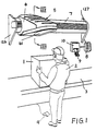
- the physical object 1 which is to be measured is placed by means of an operator 2 on a table 3, a weighing scale or another stable, invariable surface.
- the measuring apparatus in figure 1 indicated in general by means of the reference numeral 5, is advised that a measurement is required by means of a start signal given via a push button, foot pedal 4, or a command across a serial interface from an external computer (not shown).
- the measuring apparatus 5 is mounted in a measuring carriage 6 which is made to move over the object 1 along a guiding profile 7, whereby the dimensions of the object are read.
- a short time after the carriage 6 has passed over the object 1, the measured dimensions and/or parts thereof, e.g. the volume of the object, will be shown on a display 8.
- the result of the measurement may optionally also be fed to the computer.
- a print-out 9 may optionally also be provided via a printer 10.
- This print-out can, for instance, be in alphanumeric form or in the form of bar code, or optionally in the form of both.
- the print-out may optionally be of a kind such that it can be adhered to the object, so that the dimensions of the object are thus unambiguously defined in connection with possible later handling of the object.
- the measuring apparatus After an output and/or print-out has been given the measuring apparatus will be ready to measure a new object.
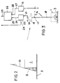
- Fig. 2 is related to problems of so-called "fields of shadow".
- the regulations are drawn up in such a way that payment has to be made for the smallest right-angled rectangular box or crate in which the object can be placed. If the path of measurement or the path of the light beam deviates from 90° towards the underlying support 3, a field of shadow 11 will occur, as illustrated in figure 2.
- the measuring apparatus will be unable to detect the content of this field of shadow.
- the angle ⁇ that the scanning light beam 12 forms with the vertical should thus be as close to 0° as possible.
- the maximum error of measurement will depend upon how much of an object to be measured is within a shadow area of this kind and that cannot be detected.
- Fig. 3 shows the measuring principle for a laser distance reader, generally denoted by the reference numeral 13.
- An oscillator 14 modulates a laser diode 15 with an FM frequency (e.g. 82 MHz).
- the laser light which is emitted from the laser diode 15 is denoted by reference numeral 16 and passes via a mirror unit 17 downwards at right angles towards the underlying support 3 on which an object may be placed.
- Light reflected back is marked with the reference numeral 18 and travels past the mirror unit 17 via optics 19 to an optical sensor 20, e.g. a photodiode which is capable of registering the received laser light.
- This received light signal is transferred via a connection 21 to an amplifier 22 which has automatic gain control (AGC).
- AGC automatic gain control
- a signal is produced at the first outlet 23 from said amplifier which is characteristic of the received luminous intensity.
- a second outlet 24 from the amplifier 22 is connected to a first input 25 on a phase measuring device 26, and an outlet 27 on the oscillator 14 is connected to a second input 28 on the phase measuring device 26.
- the distance measuring apparatus will measure the distance to the object 1 by measuring the time T1 that the light takes from when the laser beam leaves the distance measuring apparatus, hits the object 1, and is received as reflected light by the sensor 20. This time is measured by measuring, in the phase measuring device 26, the phase difference between the emitted light, as registered at the input 28, and the light reflected back, as registered at the input 25 of the phase measuring device 26. Characteristic distance values are then produced at the output of the phase measuring device 29.
- US Patent 4996440 makes known the use of a cone segment mirror to form a generally conical mirror surface to deflect the scanning beam to scan at right angles downwards to the underlying support.
- the necessary gauge length for the measuring carriage will have the value L 1 which is equal to twice the radius R 1 of the conical mirror 30, as shown in fig. 4B and also the length L 2 of the object as shown in fig. 4A.
- a polygonal mirror unit 32 is used instead of the rotating plane mirror 31 in fig. 4B.
- the mirror unit 32 is, in the preferred embodiment, made of six mirror surfaces arranged on the six sides of the polygon.
- a modified paraboloid is used, i.e., a double curved mirror or a parabola, the arc of which has a radius of curvature which is modified somewhat over the length of the mirror and which is greatest at the ends of the mirror.
- the modified paraboloid mirror is marked with the reference numeral 33.
- R 3 denotes the length of the measuring carriage which is increased relative to the known R 1 value.
- R 2 is the distance between the centre of of the mirror surfaces of the polygonal mirror unit 32 and the mid-point of the double curved mirror 33.
- R 4 generally denotes the radius of curvature of the mirror 33. However, it should be pointed out that R 2 will change gradually as the mirror 32 rotates and that this is compensated by the design of the double curved mirror 33.
- the effective measuring length that the measuring carriage must move will be equal to L 3 , which is twice the pitch 35 plus the length L 2 of the object 1.
- the measuring length will be related to effective scanning time over the object.
- the conical mirror 30 spans over an angle which is almost equal to 180°.
- said pitch 36 of this arc will be large.
- a reduction in the length of the apparatus or guiding rail 7 is achieved when the pitch 35 is reduced.
- the scanning angle for the fan-shaped scan will thus also be smaller.
- This in turn means that it is possible to use a plurality of mirror surfaces in the polygon and to rotate the polygon at a lower speed of rotation for the same scanning frequency as is used in the known solution according to fig. 4.
- the most substantial disadvantage with the solution which is outlined in fig. 5 is that the length of the measuring carriage in the direction or movement will be greater owing to the increased radius between the polygonal mirror unit and the double curved mirror 33.
- the present invention aims to make the dimensions of the measuring carriage as small as possible.
- the distance between the centre of the mirror surfaces of the polygonal mirror unit and the mid-point or the double curved mirror 33 is equal to R 2 as shown in fig. 5B.
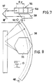
- the length of the measuring carriage will, however, be considerably reduced in that the scanning beam, which spreads out in a fan shape, will be deflected 90° twice by means of two mirrors 37 and 38 which form an angle of 90° in relation to one another, the light beam being reflected from the mirror unit 32 towards the mirror 37, thence to the mirror 38, and on further to a double curved mirror 39 so that, in the example shown in fig.
- the distance between a centre of the mirror surface of the polygonal mirror unit and the mid-point of the double curved mirror 39 has a distance R 5 .
- this solution groups the optics in two sets of mirror surfaces which are mounted directly above/below one another. As long as an even number of mirror surfaces are closely connected to one another at fixed angles in relation to one another, a rotation or translation of the two connected mirrors, which together form one system, will be of no consequence for the angle at which the light leaves the mirrors taken as a whole.
- the two folding or deflecting mirrors 37 and 38 are connected to one another in one system and the polygonal mirror unit 32 and the double curved mirror 39 are connected together in a second system within the present apparatus.
- the laser distance measuring device 13 will, by means of its laser, emit a light beam 16 in the direction of the mirror 17, whence the light beam 16 is reflected in the direction of the rotating polygonal mirror unit 32.
- This unit has, for instance, six mirror surfaces 40 mounted on the side surfaces of the polygon. Each mirror has been given a size that has been determined by the aperture of the receiving optical means 19.
- the laser light will be dispersed in a fan shape from the polygonal mirror unit 32 as this rotates. This fan-shaped light will be deflected by the mirrors 37 and 38 which are mounted at 90° relative to one another. The scanning light beam or laser light fan will thus hit a large double curved deflecting mirror 39.
- This mirror will deflect the received light beam 90° so that the light scans at right angles downwards to the underlying support 3 which is found under the measuring apparatus.
- This light that has been reflected from the object will be, as explained earlier, detected and the phase difference between the emitted laser light and the received laser light will, as previously mentioned, form the basis for calculating successive distances to the object 1 which is on the support 3.
- the light which is reflected from the object will be led via the double curved mirror 39 to the lower deflecting mirror 38, thence to the upper deflecting mirror 37, thence to the polygonal mirror unit 32, and thence via the optical means 19 to the detector 20.
- the polygonal mirror unit 32 will be driven by a motor 41, where the mirror unit constitutes a part of the motor rotor, and where the motor central stator is via a suspension or shaft 42 rigidly connected to a framework or other mounting means in the measuring carriage.
- a laser distance measuring apparatus such as the one described and illustrated here, will be capable of being exposed to a certain drift in the measurement values over time, for example because of temperature changes, aging, variation between models, etc. It will therefore be both desirable and necessary to calibrate the distance measuring apparatus whilst it is in operation.
- the light will be deflected here so as to pass through a window 45 and hit an end 46 of the guide rail or guide profile 7.
- a small plate 47 which has been given a grey toned pattern is positioned at the end 46 and from here measurements are taken during each scan.
- the trigger diodes 44 and 48 will emit a signal when the light beam meets the diodes, where starting and stopping of a scan will be indicated. This will also give a fairly reliable determination of the momentary position of the light beam along the double curved mirror 39 when the speed of the motor 41 is known or is constant, so that it can be measured exactly by means of the trigger diodes.
- a polygonal mirror unit 32 is used, the task of which being to spread out the laser beam and to pick up the light spread towards the receiver in a fan shape, as previously described, so that the object to be measured is scanned in one axial direction.
- the paths of light must be so precise that the scanning paths will be monotonously ascending with the direction of movement of the measuring carriage.
- the diameter of the polygonal unit is determined by a necessary aperture for the receiving lenses and the number of mirrors that are necessary for the desired scanning angle.
- the angle of the mirrors along the direction of rotation is assumed to be non-critical, since this will only cause a time displacement of the scan. This could be compensated for by the light passing the trigger diode 44 immediately prior to the start of the scan, and the trigger diode 48 immediately after the end of the double curved mirror 39 thereby registering the time of the end of the scan.
- the angle of the mirror transverse to the direction of rotation must however deviate very little from mirror to mirror, and in the present embodiment of the invention this angle deviation must typically be ⁇ 1 milliradian.
- the angle of the mirrors will be adjustable, according to the invention, by means of an apparatus such as the one in figs. 11 and 12.
- the polygonal unit here is made with the shaft 49 of the driving motor 41 and thus the stator of the motor secured to a holder 50 for the polygonal mirror unit.
- the motor housing will thus be connected to the mirrors 40 which are a part of the unit 32, the motor housing rotating together with the mirrors 40.
- the mirrors are deposited in a holder 51 which fixes the under side of the mirrors at two points 52 and 53.
- the upper side of the mirrors are supported at one point by a flexible metal plate 54.
- the plate 54 has, moreover, two punched-out tongues 55 and 56 which project from the centre of the metal plate 54 and come to bear against the back of the mirror in order to press the mirror out towards its abutment points uppermost and lowermost.
- a screw connection 57 causes the mirror bottom holder 51 and the flexible metal plate 54 to be held together. By tightening the screw connection 57, the metal plate 54 will be bent together, whereby the upper side of the mirror 40 will be drawn in the direction of the mid-point of the polygonal unit.
- the polygonal mirror unit is connected to the laser distance measuring apparatus 13, which can be firmly fixed to the holder 50 in such a way that the polygonal unit and the laser distance measuring apparatus thereby have their position relative to one another fixed.
- the mirrors 40 in the polygonal unit will be adjustable to the correct and possibly identical angles by manually rotating the polygonal unit 32 and observing the light path of the laser on a screen at a distance that is sufficient to make possible an accurate adjustment of the position of the paths of light.
- a pin 58 is arranged on the polygonal unit which extends down from the polygonal unit and will interrupt a light beam when it passes a light fork.
- the pin is used to identify the position of the polygon by communication with a computer so that the computer knows which of the mirrors is used in the scan at any point of time.
- the computer will be able to include possible remaining errors in the mirror angles of the polygonal unit so that such errors can be included in the calibrating algorithms of the computer.
- An ideal, fan-shaped scan is generated by a mirror which rotates around an axis which is placed in the centre of the mirror in the plane of the reflecting coating.
- the scan constitutes approx. 60°. If a double-sided mirror is used, only twice 30° of a 360°-rotation could be used which would give rise to poor efficiency in terms of time.
- the mirror surfaces are used which are assembled in a polygon, where the diameter of the polygon is determined by the size of each mirror.
- the mirror surfaces will, in this way, be displaced from the centre of rotation and this will give rise to a fan-shaped scan where the centre of rotation will, in reality, move during rotation.
- the consequence of this in the present case will be that the scanning beams which sweep over the object will not be parallel if a paraboloid is used as a double curved mirror.
- the form of this mirror is therefore modified in relation to a rotated parabola, so that the light will travel parallel down towards the object 1. This is done in practice by changing the radius value and also the position of the radius centre for the rotated parabola sufficiently along the mirror, the opposite of what will happen to the polygon after the polygon scans over the double curved mirror, whereby the error will be compensated.
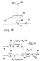
- Fig. 13 shows in more detail how the foot of the reflected beam moves along the mirror surface (and the position of the centre of the fan-shaped scan) as the mirror surface 40 rotates.
- a first position 59 for the mirror unit 32 the distance between the foot point of the beam and the centre of the mirror unit is d 3 .
- the angle between the incident beam 16 and the reflected beam 18 is equal to approx. 90°.
- the polygonal unit 32 is at position 60 (which can be seen in fig. 13) the reflection point or foot point of the incident beam 16 will have changed so that the distance from said centre will now have increased to d 4 .
- the measuring carriage 6 has a window 61.
- This window which comprises a glass plate is necessary in order to prevent a build up of dust inside the measuring apparatus 5, i.e. inside the carriage 6.
- a build up of dust could, to a great extent, affect the result of the measurement in an unfavourable direction and would moreover require constant cleaning. It is obvious that it would be simpler to clean only the surface of the window 61 on the outside of the carriage 6. As a result of dust and scratches, this window will be the greatest image for stray light. This window will represent the largest problem when it comes to shielding.
- a laser distance measuring apparatus 13 measures distance by measuring phase difference between emitted and reflected light from the object 1. This phase difference will be influenced by optical devices, if any, such as said glass plate 61, through which the light passes on its way and which partially reflects light back to the light sensor in the laser distance measuring apparatus 13.
- a window surface 61 would typically reflect 1-4% of the light and 96-99% of the light would pass through the window surface, although dependent upon the material used in the window, coating thereof, if any, etc. If the window is positioned perpendicular to the beam direction, the reflection will be captured by the receiver and will modify the distance measurement in such a way as will be understood in more detail by looking at fig.
- amplitude and phase displacement of the object to be measured is described as B 1 ⁇ 2 and that the stray light from the window is denoted A 1 ⁇ 1 .
- the signal which is measured will thereby be made a vectorial sum of these two signals, viz., k 1 ⁇ 3 . If ⁇ 1 and ⁇ 2 have a phase difference of 90°, the error will have a maximum effect.
- the emitted light typically would be in the range of 1 to 10 mW
- the light reflected back from the object to be measured would typically be in the range 50 to 1000 nW.
- the stray light must typically be ⁇ 1/100 of the retro-reflected light in order not to affect the accuracy of the measurements. This means that the stray light from the optical surfaces which is reflected back to the light sensor must be less than one millionth of the emitted light energy.
- the stray light signal Prior to being applied to the summation circuit, the stray light signal passes a phase and amplifying adjustment circuit 65 which has an amplification factor k.
- the signals are summed in that phase and amplification of the signal from the stray light detector are adjusted until the signal from a reflector (not shown), which is placed at a distance which corresponds to the outer source of stray light, provides zero signal from the circuit.
- the distance measuring apparatus will then be insensitive to stray light which is reflected at this distance.
- the main detector consists of a tuned LC-circuit 66 which serves as a filter and an amplifier 67 which has a high signal - noise ratio.
- the signal at the output 68 will thus be representative for that light which is reflected from the object 1 and from the underlying support 3.
- a so-called wedge lens 69 which refracts the light in the central part of the receiving lens 70 to the side.
- the lens 71 is an additional lens and has no significance for the understanding of how the main light and the stray light are separated in the solution shown here.
- Shields 72 and 73 are provided in order to ensure that only light in the central parts of the lens area hits the detectors 62 and 63.
- the wedge lens C an optical shielding is achieved, but it is, as indicated above, not required that one shields sufficiently for one hundred percent elimination of stray light from the outermost source of stray light in the apparatus, namely the window 61 in the measuring carriage.
- the light sensor for the main light also here denoted by the reference numeral 62, may be a PIN diode which is positioned at a focal distance which corresponds to the area of measurement, and will substantially receive light from the object being measured, and because of the wedge lens 69 receive a reduced part of stray light from the outermost source of stay light.
- the wedge lens 69 will refract light from the centre of the receiving lens 70, 71 out to the side of the main light detector 62 to the stray light sensor 63 which is positioned at a focal distance which corresponds to the outermost source of stray light, in this case the glass plate 61.
- This stray light sensor will, in the main, receive scattered light, and because of the focal distance, a reduced part of the main light.
- fig. 18 a modification of the solution in figs. 16 and 17 is shown where a lens 74 is placed in connection with the shield 75 and where the wedge shaped lens 69 is placed at a distance from the lens 74, in contrast to the solution in figs. 16 and 17. Moreover, the mirror 17 which deflects the light beam from the light source 15 is also positioned at a distance from the wedge lens 69.
- the manner of operation of this solution which is illustrated in fig. 18 will, however, correspond to that which has just been described in connection with figs. 16 and 17.
- a laser diode 76 It is expedient to equip a laser diode 76 with a fibre lens 77 for collimating the laser light.
- the fibre lens can be of the "Selfoc" kind. The positioning of this lens is important for achieving a good quality of the laser spot which is reproduced on the object being measured. Both sideways position, orientation and distance in relation to the diode laser 76 are important, and typically a positioning must be carried out with a precision which is better than 50 ⁇ m.
- a fine positioning of the fibre lens 77 is proposed in order to finely adjust the direction of the emitted laser light, which entails a further requirement of accurate positioning of the lens 77, typically with an accuracy equal to 1 ⁇ m.
- the distance between the fibre lens 77 and the laser diode 76 must be finely adjusted.
- the fibre lens 76 is put in a V-shaped groove 78 and is held in place by a spring 79.
- the lens 77 is outermost on an arm 80 which is resilient about a centre of rotation 81 which is so far away that the lens can be said to be displaced parallel to and from the laser.
- a screw 82 is fixed in the arm 80 and is drawn back and forth by a nut 83 against the tension effect of an O-ring 84. The focus of the laser will thus be adjusted by turning the nut 83.
- the retainer plate 80 for the lens 77 will be solidly secured in a retainer plate 85 by means of two screws 86 and 87.
- the retainer plate 85 is provided with two slots 88 and 89 which form arms 90, 91 and 92.
- the arms 90 and 91 are interconnected at point 93 and the arms 91 and 92 are connected at point 94.
- the lens 77 is attached to the arm 92 via the retainer plate 80 and the screw connection 86, 87.
- the side position of the fibre lens will be finely adjusted until maximum light signal from an object to be measured is received on the receiver diode 62.
- a shield 73 as is shown in fig. 16, stray light will be prevented from being scattered inside the distance measurement housing and from being able to reach the receiving diode.
- the shield 73 can be replaced by a tube (not shown) the axis of which coincides with the lens 77.
- the distance between the fibre lens 98 and the laser diode must be finely adjusted.
- the fibre lens 98 is put in an almost V-shaped groove 99 and is secured with a UV-curable glue or similar adhesive.
- the lens 98 is in a retaining plate 100 which is designed to have two slots 101 and 102 which form arms 103, 104 and 105. Furthermore, in retainer plate 100 an additional slot 106 is arranged causing the formation of two additional arms 107 and 108.
- the arms 103 and 107 are rigidly connected to one another and the arms 105 and 108 are also rigidly connected to one another.
- the arms 104 and 105 are connected to one another at a point of rotation 109 and the set of arms 105, 108 are rotatably connected to the set of arms 100, 107 via a rotational connection 110.
- the lens 99 is fixed to the arm 104 close to the point of rotation 109.
- the arm 104 By adjusting a screw 111, the arm 104 will rotate elastically about the point of rotation 109.
- the arm 105, and similarly the arm 104 will rotate elastically about the point of rotation 110.
- These adjustment screws will displace the lens sideways relative to the laser 97 along two paths of rotation which are at 90° to one another. One thus achieves independent sideways adjustment along two axial directions. Because of the difference in distance from the points of rotation to the lens and to the screws, a considerable exchange factor is achieved which enables the lens to be finely positioned.
- the laser diode 97 is mounted by means of screw connections having retainer discs 113 and 114 in an arm 115 which via a stay 116 is secured to a frame 117.
- the stay or spacer 116 can optionally be unitary with the arm 115 and the frame component 117, eg, made as an extruded profile, or the arm 115, the stay 116 and the frame component 117 can be made as separate parts which are fastened together by means of a screw connection or by gluing. Adjustment of the focus between the laser diode 97 and the fibre lens 98, i.e. the relative distance between the two elements, will be carried out by means of a screw 118 which extends between the frame component 117 and the arm 115.
- the arm 115 is attached, via the screw connections 113 and 114, to a circuit board 119 which is used, for instance, for the electronics involved in controlling the laser diode 97.
- a circuit board 119 which is used, for instance, for the electronics involved in controlling the laser diode 97.
- the circuit board 119 has no significance for the appreciation of the adjustment possibilities for the fibre lens 98 and the laser diode 97.
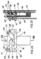
- the measuring apparatus which is described, inter alia, in connection with figs. 6 to 9, can also be seen in fig. 24.
- the measuring apparatus 5 with its carriage 6 is mounted on an aluminium profile 120 which has two grooves where, by means of cold welding, two steel rails are placed, one rail 121 on the upper side and a second rail 122 on the bottom side.
- Inside the aluminium profile there are two cavities, the rear one 125 of which having space for coupling terminals, transformers and similar.
- the ends of the profile are covered with end closures 126 and 127 (see fig.
- a front cavity 128 there runs a cable chain in which power and signal cables lie.
- the cable exits via a slot 129 in the profile 120.
- Said slot 129 is covered by a toothed belt 130 (see fig. 25).
- the toothed belt is fixedly attached at either end of the profile body 120.
- Said toothed belt 130 is lifted away from the slot 129 as the carriage moves by means of a mechanism which is in the carriage and which is shown in fig. 25.
- a motor 131 in the measuring carriage 6 draws the measuring carriage back and forth along the profile 120 (see also the reference numeral 7 in fig. 1) via an exchange 132 and a gear 133.
- the gear 133 engages with the toothed belt 130, and the toothed belt is guided over guiding casters 134, 135 and 136.
- a holder 137 projects into the profile 120 in the cavity 128 and guides the cables into the cable chain and draws the end of the cable chain with it.
- a total measuring system is thus described wherein a special feature is the design of the double curved mirror, whereby this is given a focusing power which enables the lens system to be moved effectively much closer to the object which is to be measured.
- the solid angle with which one can observe the laser spot will increase, for a given area, inversely proportional to the square of the distance. It is therefore essential to make the distance that the laser beams move as short as possible and thereby achieve the best possible accuracy of measurement.
- the necessary dimension is reduced for the subsequent components which are positioned after the first focusing mirror, especially folding mirror, polygonal mirror and lenses which are mounted right in front of the sensor unit.
Abstract
Description
- The present invention relates to an apparatus for measuring the distance to at least one part of an object for determining at least one dimension of the object, the apparatus comprising means for directing a light beam towards the object, means for registering the light beams reflected from the object, means for calculating the time the light beams take to travel to and from the object, and means causing the light beam to sweep over the object perpendicularly in relation to a fixed reference plane during the entire sweeping operation, and with relative movement between the apparatus and the object which is to be measured, the light that is reflected by the object returning to the light registration means via said light beam sweeping means, said light beam sweeping means comprising a stationary mirror, which is curved along its length to provide a a longitudinally curved surface, and a rotating polygonal mirror unit having rotor means for rotating the mirror unit to move the light beam over the stationary mirror and to receive object reflected light beams therefrom. Apparatus of this known kind is disclosed in EP-A-0346015.
- Another known apparatus is disclosed in US-A-4996440. This known solution includes a pitch in the scanning arc which corresponds to the radius of curvature of the stationary mirror. This means that the measuring apparatus must move over an unduly long distance which corresponds to the length of the object plus twice the length of said radius of curvature.
- It is therefore an objective of the present invention to reduce the radius of curvature and thereby make the measuring apparatus as compact as possible.
- In the known solutions, it is intended that the distance be measured from the measuring apparatus and down towards the underlying support along parallel, vertical light paths. However, it is not always easy to obtain such vertical and parallel paths of measurement. This makes great demands on the measuring optics. With the present invention, it is thus intended to obtain parallel paths of measurement of this kind, and also to ensure that it is possible to continuously calibrate the distance measuring apparatus while in operation.
- One objective of measuring by means of parallel, vertical lines is, inter alia, that the position of the point of measurement will not be dependent upon the vertical distance of movement of the light. In addition, it is desirable that a reflecting component in the surface of the object will at one point at least, namely the highest point, reflect the light back to the measuring apparatus. Furthermore, a principal objective of the present invention is to avoid fields of shadow.
- One of the known problems with distance reading apparatus is to be able to shield a light detector in such a way that one prevents or compensates for unwanted reflected rays or so-called scattered light in such a way that light of this kind does not reach the detector. The present invention provides a solution which enables this problem to be overcome.
- Moreover, to be able to finely adjust the position and/or focus of a lens unit of a diode laser in a simple way is known to be a problem. The present invention aims also to provide a means to enable this to be accomplished.
- Different aspects of apparatus according to the invention for measuring the distance to at least one part of an object are disclosed in ensuing claims 1 and 2.
- The characteristic features of the invention will become apparent in the patent claims hereinbelow and also in the specification with reference to the enclosed drawings.
- Fig. 1
- illustrates one use of the invention in a typical working situation.
- Fig. 2
- illustrates the problems linked with "fields of shadow".
- Fig. 3
- illustrates the measuring principle of a laser distance reader.
- Figs. 4A and 4B
- show the pitch and gauge length in connection with the prior art, e.g., as disclosed in US Patent 4996440, and Figs. 5A and 5B show the pitch of the scanning arc and the gauge length, according to the invention.
- Figs. 6, 7, 8, 9 and 10
- show in perspective view, in side view, plan view, side view and from above, respectively, details of the measuring principle according to the invention.
- Figs. 11 and 12
- illustrate in detail a polygonal mirror unit seen from below and in partial section, respectively.
- Fig. 13
- shows the deflection of laser light by means of the mirror unit.
- Fig. 14
- illustrates the problems connected with stray light.
- Fig. 15
- discloses geometrical considerations connected to the problems of stray light.
- Figs. 16 and 17
- show a first embodiment of a stray light detector.
- Fig. 18
- shows a modification of the stray light detector in figs. 16 and 17.
- Fig. 19
- shows a block diagram of a circuit for cancelling stray light.
- Fig. 20
- is a front view of a first embodiment of an apparatus for finely adjusting position and/or focus of the lens unit of a diode laser.
- Fig. 21
- shows the section XXI-XXI in fig. 20.
- Fig. 22
- shows in front view a modification of the apparatus in figs. 20 and 21.
- Fig. 23
- shows the section XXIII-XXIII in fig. 22.
- Fig. 24
- shows the measuring apparatus according to the invention placed in a carriage that can be moved back and forth.
- Fig. 25
- show a detail of the carriage in fig. 24 for the moving thereof and asspcoated cabling.
- The physical object 1 which is to be measured is placed by means of an operator 2 on a table 3, a weighing scale or another stable, invariable surface. The measuring apparatus, in figure 1 indicated in general by means of the reference numeral 5, is advised that a measurement is required by means of a start signal given via a push button, foot pedal 4, or a command across a serial interface from an external computer (not shown). The measuring apparatus 5 is mounted in a measuring carriage 6 which is made to move over the object 1 along a guiding profile 7, whereby the dimensions of the object are read. A short time after the carriage 6 has passed over the object 1, the measured dimensions and/or parts thereof, e.g. the volume of the object, will be shown on a display 8. The result of the measurement may optionally also be fed to the computer. A print-out 9 may optionally also be provided via a printer 10. This print-out can, for instance, be in alphanumeric form or in the form of bar code, or optionally in the form of both. The print-out may optionally be of a kind such that it can be adhered to the object, so that the dimensions of the object are thus unambiguously defined in connection with possible later handling of the object.
- After an output and/or print-out has been given the measuring apparatus will be ready to measure a new object.
- Fig. 2 is related to problems of so-called "fields of shadow". In the application of volume measuring for allocating tariffs for freight services, the regulations are drawn up in such a way that payment has to be made for the smallest right-angled rectangular box or crate in which the object can be placed. If the path of measurement or the path of the light beam deviates from 90° towards the underlying support 3, a field of shadow 11 will occur, as illustrated in figure 2. The measuring apparatus will be unable to detect the content of this field of shadow. The angle α that the scanning light beam 12 forms with the vertical should thus be as close to 0° as possible. The maximum error of measurement will depend upon how much of an object to be measured is within a shadow area of this kind and that cannot be detected. As an example, let us assume that one has a package that is of a height equal to 700 mm and a specified accuracy of measurement of the measuring apparatus that is equal to 5 mm. With a solution of this kind the angle α must deviate with < 5/700 rad (equal to approx. 7.6 milliradians). If one wishes to take into consideration deviations which may go each in their own direction on either side of the package, the angle must be < 3.5 milliradians.
- Fig. 3 shows the measuring principle for a laser distance reader, generally denoted by the reference numeral 13. An oscillator 14 modulates a laser diode 15 with an FM frequency (e.g. 82 MHz). The laser light which is emitted from the laser diode 15 is denoted by reference numeral 16 and passes via a mirror unit 17 downwards at right angles towards the underlying support 3 on which an object may be placed. Light reflected back is marked with the reference numeral 18 and travels past the mirror unit 17 via optics 19 to an optical sensor 20, e.g. a photodiode which is capable of registering the received laser light. This received light signal is transferred via a connection 21 to an amplifier 22 which has automatic gain control (AGC). A signal is produced at the first outlet 23 from said amplifier which is characteristic of the received luminous intensity. A second outlet 24 from the amplifier 22 is connected to a first input 25 on a phase measuring device 26, and an outlet 27 on the oscillator 14 is connected to a second input 28 on the phase measuring device 26. The distance measuring apparatus will measure the distance to the object 1 by measuring the time T1 that the light takes from when the laser beam leaves the distance measuring apparatus, hits the object 1, and is received as reflected light by the sensor 20. This time is measured by measuring, in the phase measuring device 26, the phase difference between the emitted light, as registered at the input 28, and the light reflected back, as registered at the input 25 of the phase measuring device 26. Characteristic distance values are then produced at the output of the phase measuring device 29.
- US Patent 4996440 makes known the use of a cone segment mirror to form a generally conical mirror surface to deflect the scanning beam to scan at right angles downwards to the underlying support. With a solution of this kind, as indicated in fig. 4, the necessary gauge length for the measuring carriage will have the value L1 which is equal to twice the radius R1 of the conical mirror 30, as shown in fig. 4B and also the length L2 of the object as shown in fig. 4A.
- In the present invention, as is made apparent in figs. 5A and 5B, instead of the rotating plane mirror 31 in fig. 4B, a polygonal mirror unit 32 is used. The mirror unit 32 is, in the preferred embodiment, made of six mirror surfaces arranged on the six sides of the polygon. According to the present invention, instead of the conical mirror 30, a modified paraboloid is used, i.e., a double curved mirror or a parabola, the arc of which has a radius of curvature which is modified somewhat over the length of the mirror and which is greatest at the ends of the mirror. In fig. 5B, the modified paraboloid mirror is marked with the reference numeral 33. Here R3 denotes the length of the measuring carriage which is increased relative to the known R1 value. R2 is the distance between the centre of of the mirror surfaces of the polygonal mirror unit 32 and the mid-point of the double curved mirror 33. R4 generally denotes the radius of curvature of the mirror 33. However, it should be pointed out that R2 will change gradually as the mirror 32 rotates and that this is compensated by the design of the double curved mirror 33.
- It is sideways component d1, in particular, that is the problem when using the polygonal mirror, see fig. 13. The shifting d2 of the foot point along the mirror surface does not, however, cause such great problems. To compensate for said shifting d1 in particular, R4 will be greater at the ends of the mirror 33 than at the mid point 33'. Thus, at said ends in particular, R4 > R2, see fig. 5B. Furthermore, the pitch 35 of the scanning path 34 will be considerably smaller, preferably approx. 15-30% of the radius of curvature or the pitch 36 which is made possible according to the solution shown in fig. 4A, but on the other hand the length of measuring carriage increases.
- However, this means that the effective measuring length that the measuring carriage must move will be equal to L3, which is twice the pitch 35 plus the length L2 of the object 1. The measuring length will be related to effective scanning time over the object.
- As will be seen from fig. 4, the conical mirror 30 spans over an angle which is almost equal to 180°. One problem with a solution of this kind is that said pitch 36 of this arc will be large. With the solution according to the invention, a reduction in the length of the apparatus or guiding rail 7 is achieved when the pitch 35 is reduced. The scanning angle for the fan-shaped scan will thus also be smaller. This in turn means that it is possible to use a plurality of mirror surfaces in the polygon and to rotate the polygon at a lower speed of rotation for the same scanning frequency as is used in the known solution according to fig. 4. The most substantial disadvantage with the solution which is outlined in fig. 5 is that the length of the measuring carriage in the direction or movement will be greater owing to the increased radius between the polygonal mirror unit and the double curved mirror 33.
- As will be described in more detail in connection with figs. 6 to 10, the present invention aims to make the dimensions of the measuring carriage as small as possible.
- Before figs. 6 to 8 are described in more detail, a brief reference will be made to fig. 9. In the solution illustrated therein, the distance between the centre of the mirror surfaces of the polygonal mirror unit and the mid-point or the double curved mirror 33 is equal to R2 as shown in fig. 5B. The length of the measuring carriage will, however, be considerably reduced in that the scanning beam, which spreads out in a fan shape, will be deflected 90° twice by means of two mirrors 37 and 38 which form an angle of 90° in relation to one another, the light beam being reflected from the mirror unit 32 towards the mirror 37, thence to the mirror 38, and on further to a double curved mirror 39 so that, in the example shown in fig. 7, the distance between a centre of the mirror surface of the polygonal mirror unit and the mid-point of the double curved mirror 39 has a distance R5. In this way a considerable reduction of the total dimensions of the apparatus is achieved. In addition to giving rise to a more compact measuring carriage, which is somewhat at the expense of the height of the carriage, this solution groups the optics in two sets of mirror surfaces which are mounted directly above/below one another. As long as an even number of mirror surfaces are closely connected to one another at fixed angles in relation to one another, a rotation or translation of the two connected mirrors, which together form one system, will be of no consequence for the angle at which the light leaves the mirrors taken as a whole. Thus, the two folding or deflecting mirrors 37 and 38 are connected to one another in one system and the polygonal mirror unit 32 and the double curved mirror 39 are connected together in a second system within the present apparatus.
- The laser distance measuring device 13 will, by means of its laser, emit a light beam 16 in the direction of the mirror 17, whence the light beam 16 is reflected in the direction of the rotating polygonal mirror unit 32. This unit has, for instance, six mirror surfaces 40 mounted on the side surfaces of the polygon. Each mirror has been given a size that has been determined by the aperture of the receiving optical means 19. The laser light will be dispersed in a fan shape from the polygonal mirror unit 32 as this rotates. This fan-shaped light will be deflected by the mirrors 37 and 38 which are mounted at 90° relative to one another. The scanning light beam or laser light fan will thus hit a large double curved deflecting mirror 39. This mirror will deflect the received light beam 90° so that the light scans at right angles downwards to the underlying support 3 which is found under the measuring apparatus. This light that has been reflected from the object will be, as explained earlier, detected and the phase difference between the emitted laser light and the received laser light will, as previously mentioned, form the basis for calculating successive distances to the object 1 which is on the support 3.
- As will be understood immediately, the light which is reflected from the object will be led via the double curved mirror 39 to the lower deflecting mirror 38, thence to the upper deflecting mirror 37, thence to the polygonal mirror unit 32, and thence via the optical means 19 to the detector 20.
- As will be understood from fig. 6, the polygonal mirror unit 32 will be driven by a motor 41, where the mirror unit constitutes a part of the motor rotor, and where the motor central stator is via a suspension or shaft 42 rigidly connected to a framework or other mounting means in the measuring carriage.
- A laser distance measuring apparatus, such as the one described and illustrated here, will be capable of being exposed to a certain drift in the measurement values over time, for example because of temperature changes, aging, variation between models, etc. It will therefore be both desirable and necessary to calibrate the distance measuring apparatus whilst it is in operation. For this purpose it is proposed, according to the invention, to provide a mirror 43 at the end of the double curved mirror 39, i.e. between a trigger diode and the mirror 39. The light will be deflected here so as to pass through a window 45 and hit an end 46 of the guide rail or guide profile 7. A small plate 47 which has been given a grey toned pattern is positioned at the end 46 and from here measurements are taken during each scan. When the carriage 6 moves along the rail 7 the position of the carriage is measured by means of a pulse generator on the drive motor of the carriage. This pulse generator operates a counter circuit which will be zero set at the end position of the rail. Thus, from this counter absolute information is obtained with regard to the position of the carriage and this is used for calibrating the distance measuring apparatus. The grey toned pattern on the plate will provide measurements of different luminous intensity.
- The trigger diodes 44 and 48, as shown in figures 8 and 10, will emit a signal when the light beam meets the diodes, where starting and stopping of a scan will be indicated. This will also give a fairly reliable determination of the momentary position of the light beam along the double curved mirror 39 when the speed of the motor 41 is known or is constant, so that it can be measured exactly by means of the trigger diodes.
- In the present invention, a polygonal mirror unit 32 is used, the task of which being to spread out the laser beam and to pick up the light spread towards the receiver in a fan shape, as previously described, so that the object to be measured is scanned in one axial direction. However, it is considerably difficult to construct a polygonal mirror unit of this kind with precision sufficient to ensure that the paths of light, generated by the six mirrors (in the chosen exemplary embodiment), are as identical as possible. As a minimum requirement, the paths of light must be so precise that the scanning paths will be monotonously ascending with the direction of movement of the measuring carriage.
- The diameter of the polygonal unit is determined by a necessary aperture for the receiving lenses and the number of mirrors that are necessary for the desired scanning angle. The angle of the mirrors along the direction of rotation is assumed to be non-critical, since this will only cause a time displacement of the scan. This could be compensated for by the light passing the trigger diode 44 immediately prior to the start of the scan, and the trigger diode 48 immediately after the end of the double curved mirror 39 thereby registering the time of the end of the scan.
- The angle of the mirror transverse to the direction of rotation must however deviate very little from mirror to mirror, and in the present embodiment of the invention this angle deviation must typically be < 1 milliradian.
- The angle of the mirrors will be adjustable, according to the invention, by means of an apparatus such as the one in figs. 11 and 12. The polygonal unit here is made with the shaft 49 of the driving motor 41 and thus the stator of the motor secured to a holder 50 for the polygonal mirror unit. The motor housing will thus be connected to the mirrors 40 which are a part of the unit 32, the motor housing rotating together with the mirrors 40.
- The mirrors are deposited in a holder 51 which fixes the under side of the mirrors at two points 52 and 53. The upper side of the mirrors are supported at one point by a flexible metal plate 54. The plate 54 has, moreover, two punched-out tongues 55 and 56 which project from the centre of the metal plate 54 and come to bear against the back of the mirror in order to press the mirror out towards its abutment points uppermost and lowermost. A screw connection 57 causes the mirror bottom holder 51 and the flexible metal plate 54 to be held together. By tightening the screw connection 57, the metal plate 54 will be bent together, whereby the upper side of the mirror 40 will be drawn in the direction of the mid-point of the polygonal unit. If the screw is loosened, the mirror will move outwards as a result of the spring effect of the metal plate 54. The form of the metal plate makes it possible to obtain considerable exchange between the downwards bending of the plate and the position adjustment of the mirror. The polygonal mirror unit is connected to the laser distance measuring apparatus 13, which can be firmly fixed to the holder 50 in such a way that the polygonal unit and the laser distance measuring apparatus thereby have their position relative to one another fixed. By installing the distance measuring apparatus/polygonal unit in a bench, and turning the laser on, the mirrors 40 in the polygonal unit will be adjustable to the correct and possibly identical angles by manually rotating the polygonal unit 32 and observing the light path of the laser on a screen at a distance that is sufficient to make possible an accurate adjustment of the position of the paths of light.
- A pin 58 is arranged on the polygonal unit which extends down from the polygonal unit and will interrupt a light beam when it passes a light fork. The pin is used to identify the position of the polygon by communication with a computer so that the computer knows which of the mirrors is used in the scan at any point of time. Thus the computer will be able to include possible remaining errors in the mirror angles of the polygonal unit so that such errors can be included in the calibrating algorithms of the computer.
- An ideal, fan-shaped scan is generated by a mirror which rotates around an axis which is placed in the centre of the mirror in the plane of the reflecting coating. However, it is only possible to achieve this by using one or two mirror surfaces (double-sided mirrors). In the present invention, the scan constitutes approx. 60°. If a double-sided mirror is used, only twice 30° of a 360°-rotation could be used which would give rise to poor efficiency in terms of time.
- To make better use of the distance measuring apparatus, according to the preferred yet not limitative embodiment of the invention, six mirror surfaces are used which are assembled in a polygon, where the diameter of the polygon is determined by the size of each mirror. The mirror surfaces will, in this way, be displaced from the centre of rotation and this will give rise to a fan-shaped scan where the centre of rotation will, in reality, move during rotation. The consequence of this in the present case will be that the scanning beams which sweep over the object will not be parallel if a paraboloid is used as a double curved mirror. In the present invention, the form of this mirror is therefore modified in relation to a rotated parabola, so that the light will travel parallel down towards the object 1. This is done in practice by changing the radius value and also the position of the radius centre for the rotated parabola sufficiently along the mirror, the opposite of what will happen to the polygon after the polygon scans over the double curved mirror, whereby the error will be compensated.
- Fig. 13 shows in more detail how the foot of the reflected beam moves along the mirror surface (and the position of the centre of the fan-shaped scan) as the mirror surface 40 rotates. At a first position 59 for the mirror unit 32 the distance between the foot point of the beam and the centre of the mirror unit is d3. Furthermore, the angle between the incident beam 16 and the reflected beam 18 is equal to approx. 90°. When the polygonal unit 32 is at position 60 (which can be seen in fig. 13) the reflection point or foot point of the incident beam 16 will have changed so that the distance from said centre will now have increased to d4. The angle between the incident beam 16 and the exiting beam 18 is in this case β, e.g. 30°. Moving the centre 40' of the mirror surface 40 over the distance d2 thus causes the foot point of the reflected beam to move over the distance
- It will thus be understood that the movement (sideways and in/out) of the centre of rotation must be compensated, and this happens in that the radius of curvature of the double curved mirror is varied along the length thereof.
- As is made clear in fig. 1, the measuring carriage 6 has a window 61. This window which comprises a glass plate is necessary in order to prevent a build up of dust inside the measuring apparatus 5, i.e. inside the carriage 6. A build up of dust could, to a great extent, affect the result of the measurement in an unfavourable direction and would moreover require constant cleaning. It is obvious that it would be simpler to clean only the surface of the window 61 on the outside of the carriage 6. As a result of dust and scratches, this window will be the greatest image for stray light. This window will represent the largest problem when it comes to shielding.
- However, when using a window glass plate of this kind, unwanted light reflexes may occur therefrom, so-called stray light. The problems associated with this will be explained in more detail in connection with figs. 14 and 15 and thereafter also in connection with figs. 16 to 19.
- A laser distance measuring apparatus 13 measures distance by measuring phase difference between emitted and reflected light from the object 1. This phase difference will be influenced by optical devices, if any, such as said glass plate 61, through which the light passes on its way and which partially reflects light back to the light sensor in the laser distance measuring apparatus 13. A window surface 61 would typically reflect 1-4% of the light and 96-99% of the light would pass through the window surface, although dependent upon the material used in the window, coating thereof, if any, etc. If the window is positioned perpendicular to the beam direction, the reflection will be captured by the receiver and will modify the distance measurement in such a way as will be understood in more detail by looking at fig. 15 together with the following mathematical expressions:
- One will see here that amplitude and phase displacement of the object to be measured is described as B12 and that the stray light from the window is denoted A11. The signal which is measured will thereby be made a vectorial sum of these two signals, viz., k13. If 1 and 2 have a phase difference of 90°, the error will have a maximum effect.
- Whilst the emitted light typically would be in the range of 1 to 10 mW, the light reflected back from the object to be measured would typically be in the range 50 to 1000 nW. The stray light must typically be < 1/100 of the retro-reflected light in order not to affect the accuracy of the measurements. This means that the stray light from the optical surfaces which is reflected back to the light sensor must be less than one millionth of the emitted light energy.
- It is therefore essential to be able to detect both stray light and light which is received from the object being measured in order to be able to cancel the effect of the stray light source. The theory behind this will be understood in more detail by looking briefly at fig. 19 and the explanation hereinbelow.
- Light from the source of stray light is denoted Ls and light from the object being measured is designated Lm. Furthermore, suppose that the light energy on the main detector is LH and on the stray light detector is LB. The following is thus obtained:
- wherein k1 << k2 and k3 >> k4
- Now suppose that the electric response to these signals in the light sensor 62 and 63 is summed electrically in a summation circuit 64 so that: Ltot = LH - k*LB
- Prior to being applied to the summation circuit, the stray light signal passes a phase and amplifying adjustment circuit 65 which has an amplification factor k.
- By setting the amplification factor
- In the electrical arrangement in fig. 19 the signals are summed in that phase and amplification of the signal from the stray light detector are adjusted until the signal from a reflector (not shown), which is placed at a distance which corresponds to the outer source of stray light, provides zero signal from the circuit. The distance measuring apparatus will then be insensitive to stray light which is reflected at this distance.
- Since the quantity of stray light on the stray light detector 63 is greater than on the main detector 62, only a small part of the signal in the stray light detector will be inter-mixed with the main signal. Noise from the stray light detector and its amplifier will therefore only to a small degree affect the signal - noise ratio of the main detector. The main detector consists of a tuned LC-circuit 66 which serves as a filter and an amplifier 67 which has a high signal - noise ratio. The signal at the output 68 will thus be representative for that light which is reflected from the object 1 and from the underlying support 3.
- In order to be able to detect both main light and stray light, it is essential to be able to separate the two types of light optically.
- In fig. 16 a so-called wedge lens 69 is shown which refracts the light in the central part of the receiving lens 70 to the side. The lens 71 is an additional lens and has no significance for the understanding of how the main light and the stray light are separated in the solution shown here. Shields 72 and 73 are provided in order to ensure that only light in the central parts of the lens area hits the detectors 62 and 63. By using the wedge lens C an optical shielding is achieved, but it is, as indicated above, not required that one shields sufficiently for one hundred percent elimination of stray light from the outermost source of stray light in the apparatus, namely the window 61 in the measuring carriage. The light sensor for the main light, also here denoted by the reference numeral 62, may be a PIN diode which is positioned at a focal distance which corresponds to the area of measurement, and will substantially receive light from the object being measured, and because of the wedge lens 69 receive a reduced part of stray light from the outermost source of stay light.
- As will be seen in more detail from fig. 17, the wedge lens 69 will refract light from the centre of the receiving lens 70, 71 out to the side of the main light detector 62 to the stray light sensor 63 which is positioned at a focal distance which corresponds to the outermost source of stray light, in this case the glass plate 61. This stray light sensor will, in the main, receive scattered light, and because of the focal distance, a reduced part of the main light.
- In fig. 18 a modification of the solution in figs. 16 and 17 is shown where a lens 74 is placed in connection with the shield 75 and where the wedge shaped lens 69 is placed at a distance from the lens 74, in contrast to the solution in figs. 16 and 17. Moreover, the mirror 17 which deflects the light beam from the light source 15 is also positioned at a distance from the wedge lens 69. The manner of operation of this solution which is illustrated in fig. 18 will, however, correspond to that which has just been described in connection with figs. 16 and 17.
- In connection with a measuring apparatus of the present type or other measuring apparatus where accurate positioning of the emitted laser beam is required, it is essential that the focusing and adjustment of a diode laser can be carried out in a simple, yet accurate manner.
- In this connection closer reference shall be made to figs. 20 and 21. It is expedient to equip a laser diode 76 with a fibre lens 77 for collimating the laser light. The fibre lens can be of the "Selfoc" kind. The positioning of this lens is important for achieving a good quality of the laser spot which is reproduced on the object being measured. Both sideways position, orientation and distance in relation to the diode laser 76 are important, and typically a positioning must be carried out with a precision which is better than 50 µm. For this purpose, according to the invention, a fine positioning of the fibre lens 77 is proposed in order to finely adjust the direction of the emitted laser light, which entails a further requirement of accurate positioning of the lens 77, typically with an accuracy equal to 1µm.
- To be able to adjust focus, the distance between the fibre lens 77 and the laser diode 76 must be finely adjusted. The fibre lens 76 is put in a V-shaped groove 78 and is held in place by a spring 79. The lens 77 is outermost on an arm 80 which is resilient about a centre of rotation 81 which is so far away that the lens can be said to be displaced parallel to and from the laser. A screw 82 is fixed in the arm 80 and is drawn back and forth by a nut 83 against the tension effect of an O-ring 84. The focus of the laser will thus be adjusted by turning the nut 83.
- To obtain side positioning of the lens in relation to the laser diode, the retainer plate 80 for the lens 77 will be solidly secured in a retainer plate 85 by means of two screws 86 and 87. The retainer plate 85 is provided with two slots 88 and 89 which form arms 90, 91 and 92. The arms 90 and 91 are interconnected at point 93 and the arms 91 and 92 are connected at point 94. The lens 77 is attached to the arm 92 via the retainer plate 80 and the screw connection 86, 87.
- By adjusting a screw 95, the arm 92 will rotate elastically around the point of rotation 94. By adjusting a screw 96, the arm 90, and also the arm 92, will rotate elastically around the point 93. These adjustment screws 95 and 96 will thus displace the lens 77 sideways relative to the laser 76 along two paths of rotation which are at 90° to one another. One thus achieves independent sideways adjustment along the two axial directions. Owing to the difference in distance from the points of rotation to the lens and to the screws, a considerable exchange factor is achieved which makes possible the fine positioning of the lens.
- In order for the emitted laser light to coincide exactly with the optical axis of the receiving optical means, the side position of the fibre lens will be finely adjusted until maximum light signal from an object to be measured is received on the receiver diode 62. By using a shield 73, as is shown in fig. 16, stray light will be prevented from being scattered inside the distance measurement housing and from being able to reach the receiving diode. Possibly, the shield 73 can be replaced by a tube (not shown) the axis of which coincides with the lens 77.
- A variant of the adjustment apparatus which is shown in figs. 20 and 21 can be seen in the attached figs. 22 and 23.
- To adjust the focus of the laser diode 97, the distance between the fibre lens 98 and the laser diode must be finely adjusted.
- The fibre lens 98 is put in an almost V-shaped groove 99 and is secured with a UV-curable glue or similar adhesive. The lens 98 is in a retaining plate 100 which is designed to have two slots 101 and 102 which form arms 103, 104 and 105. Furthermore, in retainer plate 100 an additional slot 106 is arranged causing the formation of two additional arms 107 and 108. The arms 103 and 107 are rigidly connected to one another and the arms 105 and 108 are also rigidly connected to one another. The arms 104 and 105 are connected to one another at a point of rotation 109 and the set of arms 105, 108 are rotatably connected to the set of arms 100, 107 via a rotational connection 110. As can be seen from fig. 22, the lens 99 is fixed to the arm 104 close to the point of rotation 109.
- By adjusting a screw 111, the arm 104 will rotate elastically about the point of rotation 109. By adjusting a screw 112, the arm 105, and similarly the arm 104, will rotate elastically about the point of rotation 110. These adjustment screws will displace the lens sideways relative to the laser 97 along two paths of rotation which are at 90° to one another. One thus achieves independent sideways adjustment along two axial directions. Because of the difference in distance from the points of rotation to the lens and to the screws, a considerable exchange factor is achieved which enables the lens to be finely positioned. The laser diode 97 is mounted by means of screw connections having retainer discs 113 and 114 in an arm 115 which via a stay 116 is secured to a frame 117. The stay or spacer 116 can optionally be unitary with the arm 115 and the frame component 117, eg, made as an extruded profile, or the arm 115, the stay 116 and the frame component 117 can be made as separate parts which are fastened together by means of a screw connection or by gluing. Adjustment of the focus between the laser diode 97 and the fibre lens 98, i.e. the relative distance between the two elements, will be carried out by means of a screw 118 which extends between the frame component 117 and the arm 115. Bending of the arm 115 will take place near the stay or spacer 116, and because of the short distance of movement of the laser diode 97 relative to the fibre lens 98, seen in relation to the length of the arm 115, the movement between the two elements 97 and 98 will be almost parallel.
- The arm 115 is attached, via the screw connections 113 and 114, to a circuit board 119 which is used, for instance, for the electronics involved in controlling the laser diode 97. However, it will be understood that the circuit board 119 has no significance for the appreciation of the adjustment possibilities for the fibre lens 98 and the laser diode 97.
- The measuring apparatus, which is described, inter alia, in connection with figs. 6 to 9, can also be seen in fig. 24. The measuring apparatus 5 with its carriage 6 is mounted on an aluminium profile 120 which has two grooves where, by means of cold welding, two steel rails are placed, one rail 121 on the upper side and a second rail 122 on the bottom side. Three casters provided with ball bearings, of which only two casters 123 and 124 are shown, slide along these steel rails 121 and 122 and carry the carriage 6. Inside the aluminium profile there are two cavities, the rear one 125 of which having space for coupling terminals, transformers and similar. The ends of the profile are covered with end closures 126 and 127 (see fig. 1) and there there are attachments for fixing the profile to ceiling, wall or on a floor stand. In a front cavity 128 there runs a cable chain in which power and signal cables lie. The cable exits via a slot 129 in the profile 120. Said slot 129 is covered by a toothed belt 130 (see fig. 25). The toothed belt is fixedly attached at either end of the profile body 120. Said toothed belt 130 is lifted away from the slot 129 as the carriage moves by means of a mechanism which is in the carriage and which is shown in fig. 25. A motor 131 in the measuring carriage 6 draws the measuring carriage back and forth along the profile 120 (see also the reference numeral 7 in fig. 1) via an exchange 132 and a gear 133. The gear 133 engages with the toothed belt 130, and the toothed belt is guided over guiding casters 134, 135 and 136. A holder 137 projects into the profile 120 in the cavity 128 and guides the cables into the cable chain and draws the end of the cable chain with it.
- By means of the present invention, a total measuring system is thus described wherein a special feature is the design of the double curved mirror, whereby this is given a focusing power which enables the lens system to be moved effectively much closer to the object which is to be measured. The solid angle with which one can observe the laser spot will increase, for a given area, inversely proportional to the square of the distance. It is therefore essential to make the distance that the laser beams move as short as possible and thereby achieve the best possible accuracy of measurement. Furthermore, the necessary dimension is reduced for the subsequent components which are positioned after the first focusing mirror, especially folding mirror, polygonal mirror and lenses which are mounted right in front of the sensor unit.
Claims (10)
- An apparatus for measuring the distance to at least one part of an object (1) for determining at least one dimension of the object, the apparatus comprising means (13,32,39) for directing a light beam towards the object (1), means (20,22) for registering light beams reflected from the object, means (26) for calculating the time the light beams take to travel to and from the object, and means (32,39) causing the light beam to sweep over the object perpendicularly in relation to a fixed reference plane during the entire sweeping operation, and with relative movement between the apparatus and the object which is to be measured, the light that is reflected by the object returning to the light registration means (20,22) via said light beam sweeping means (32,39), said light beam sweeping means comprising a stationary mirror (39), which is curved along its length to provide a longitudinally curved surface, and a rotating polygonal mirror unit (32) having rotor means (41) for rotating the mirror unit to move the light beam over the stationary mirror and to receive object reflected light beams therefrom, characterised in that the stationary mirror (39), in addition to being curved along its length, has a curved cross-section so that the mirror forms a double concave mirror surface, and in that the radius of curvature of said longitudinally curved surface of the stationary mirror (39) changes along the length of the stationary mirror.
- An apparatus for measuring the distance to at least one part of an object (1) for determining at least one dimension of the object, the apparatus comprising means (13,32,39) for directing a light beam towards the object (1), means (20,22) for registering light beams reflected from the object, means (26) for calculating the time it takes for the light beams to travel to and from the object, and means (32,39) causing the light beam to sweep across the object perpendicularly in relation to a fixed reference plane during the entire sweeping operation, and with relative movement between the apparatus and the object which is to be measured, the light which is reflected by the object returning back to the light registration means (20,22) via said light beam sweeping means (32,39), said light beam sweeping means including a stationary mirror (39), which is curved along its length to provide a longitudinally curved surface, and a rotating polygonal mirror unit (32) having a rotor means, characterised in that the apparatus further comprises a first mirror (17), a plane second mirror (37), and a plane third mirror (38) which forms an angle of 90° with the second mirror (37), in that the light beam (16) which is emitted from a light generator (15) has a path of movement via the first mirror (17), thence via the polygonal mirror unit (32), thence towards the second mirror (37), thence to the third mirror (38), thence to the stationary mirror (39), and thence towards the object (1), the light beam (18) reflected from the object (1) having a path of movement back to the light registration means via the stationary mirror (39), said third (38) and second (37) mirrors, and the polygonal mirror unit (32), in that said stationary mirror (39), in addition to being curved along its length, has a curved cross section so that the mirror forms a double concave mirror surface, and in that the radius of curvature of said longitudinally curved surface of the stationary mirror (39) changes along the length of the stationary mirror.
- An apparatus according to claim 2, characterised in that said second mirror (37) and the rotating polygonal mirror unit (32) are located at a first level and said third mirror (38) and said stationary mirror (39) are located at a second level.
- An apparatus according to claim 1, 2 or 3, characterised in that the rotating polygonal mirror unit (32) is arranged at a distance above the stationary mirror (39).
- An apparatus according to any one of the preceding claims, characterised in that said rotating polygonal mirror unit (32) has individually adjustable mirrors (40).
- An apparatus according to claim 5, characterised in that each of said adjustable mirrors (40), along a first edge thereof, is mounted in a respective receiving groove (51) on said rotor means (41), said groove (51) having its axis located transverse to the axis of rotation of said rotor means, and in that each said adjustable mirror, along a second edge thereof parallel to said first edge, is adjustably attached to said rotor means (41) by means of a spring element in the form of a metal plate, said spring element (54-56) being adjustable by means of a screw/nut connection (57) which is attached to said rotor means (41) at one end and at the other end engages said spring element, said spring element having its bending curvature changed upon adjustment of said screw/nut connection to cause said adjustable mirror to be moved correspondingly in a direction towards or away from a mid point of said polygonal mirror unit (32).
- An apparatus according to claim 6, characterised in that said metal plate has a first portion (54) extending over said second edge and engaging a front face of said adjustable mirror (40) and a second portion in the form of two punched-out tongues (55,56) having the free ends thereof bearing against a rear face portion of said adjustable mirror.
- An apparatus according to any one of the preceding claims, characterised in that the longitudinally curved surface of said stationary mirror spans over an arc that is less than 180°.
- An apparatus according to any one of the preceding claims, characterised in that the pitch of the stationary mirror (39), defined as the distance between a chord drawn between the ends of the mirror and to the mid-point of the mirror is appreciably less than the smallest radius of curvature of the longitudinally curved surface of the stationary mirror, preferably approximately 15-30% of said radius of curvature.
- An apparatus according to any one of the preceding claims, characterised in that, at one end of the stationary mirror, an additional mirror (43) is positioned which deflects received light beams from the light generator (15) along the path of movement of the apparatus in the direction of a reference plate (47) having areas of different reflective properties, and which is securely fixed to one end (46) of a rail system (7) along which a carriage (5) for the apparatus can move, the time it takes the light beam to travel from said reference plate to the light registration means being a function of the position of the apparatus/carriage relative to the rail system.
Priority Applications (1)
| Application Number | Priority Date | Filing Date | Title |
|---|---|---|---|
| EP00100755A EP1003050A3 (en) | 1993-05-13 | 1994-05-13 | Light beam deflecting apparatus |
Applications Claiming Priority (3)
| Application Number | Priority Date | Filing Date | Title |
|---|---|---|---|
| NO931741 | 1993-05-13 | ||
| NO931741A NO301191B1 (en) | 1993-05-13 | 1993-05-13 | Device for measuring object dimensions |
| PCT/NO1994/000090 WO1994027166A1 (en) | 1993-05-13 | 1994-05-13 | An apparatus for measuring the dimensions of objects |
Related Child Applications (1)
| Application Number | Title | Priority Date | Filing Date |
|---|---|---|---|
| EP00100755A Division EP1003050A3 (en) | 1993-05-13 | 1994-05-13 | Light beam deflecting apparatus |
Publications (2)
| Publication Number | Publication Date |
|---|---|
| EP0705445A1 EP0705445A1 (en) | 1996-04-10 |
| EP0705445B1 true EP0705445B1 (en) | 2000-08-23 |
Family
ID=19896087
Family Applications (2)
| Application Number | Title | Priority Date | Filing Date |
|---|---|---|---|
| EP00100755A Withdrawn EP1003050A3 (en) | 1993-05-13 | 1994-05-13 | Light beam deflecting apparatus |
| EP94916438A Expired - Lifetime EP0705445B1 (en) | 1993-05-13 | 1994-05-13 | An apparatus for measuring the dimensions of objects |
Family Applications Before (1)
| Application Number | Title | Priority Date | Filing Date |
|---|---|---|---|
| EP00100755A Withdrawn EP1003050A3 (en) | 1993-05-13 | 1994-05-13 | Light beam deflecting apparatus |
Country Status (8)
| Country | Link |
|---|---|
| US (2) | US5742068A (en) |
| EP (2) | EP1003050A3 (en) |
| JP (1) | JP3287850B2 (en) |
| AT (1) | ATE195813T1 (en) |
| AU (1) | AU6817094A (en) |
| DE (1) | DE69425659T2 (en) |
| NO (1) | NO301191B1 (en) |
| WO (1) | WO1994027166A1 (en) |
Cited By (4)
| Publication number | Priority date | Publication date | Assignee | Title |
|---|---|---|---|---|
| US6705526B1 (en) | 1995-12-18 | 2004-03-16 | Metrologic Instruments, Inc. | Automated method of and system for dimensioning objects transported through a work environment using contour tracing, vertice detection, corner point detection, and corner point reduction methods on two-dimensional range data maps captured by an amplitude modulated laser scanning beam |
| US6971580B2 (en) | 1999-06-07 | 2005-12-06 | Metrologic Instruments, Inc. | Automated method of and system for dimensioning objects over a conveyor belt structure by applying contouring tracing, vertice detection, corner point detection, and corner point reduction methods to two-dimensional range data maps of the space above the conveyor belt captured by an amplitude modulated laser scanning beam |
| US7344082B2 (en) | 2002-01-02 | 2008-03-18 | Metrologic Instruments, Inc. | Automated method of and system for dimensioning objects over a conveyor belt structure by applying contouring tracing, vertice detection, corner point detection, and corner point reduction methods to two-dimensional range data maps of the space above the conveyor belt captured by an amplitude modulated laser scanning beam |
| EP3203180A1 (en) | 2016-02-04 | 2017-08-09 | Mettler-Toledo GmbH | Apparatus and methods for dimensioning an object carried by a vehicle moving in a field of measurement |
Families Citing this family (24)
| Publication number | Priority date | Publication date | Assignee | Title |
|---|---|---|---|---|
| AT403739B (en) * | 1995-05-18 | 1998-05-25 | Gec Alsthom T & D Ges Mbh | DEVICE FOR DETECTING THE MEASUREMENT OF A MOVING OBJECT |
| US5661561A (en) * | 1995-06-02 | 1997-08-26 | Accu-Sort Systems, Inc. | Dimensioning system |
| US6456415B1 (en) * | 1999-06-02 | 2002-09-24 | Fuji Photo Film Co., Ltd. | Optical scanner |
| US7087892B2 (en) * | 2000-08-18 | 2006-08-08 | Matsushita Electric Industrial Co., Ltd. | Light scanner and image forming apparatus using the same |
| WO2002080510A1 (en) * | 2001-03-30 | 2002-10-10 | Gregory Jon Tarrant | Apparatus and method for service calling |
| US7447558B2 (en) | 2004-09-18 | 2008-11-04 | The Ohio Willow Wood Company | Apparatus for determining a three dimensional shape of an object |
| US8294809B2 (en) | 2005-05-10 | 2012-10-23 | Advanced Scientific Concepts, Inc. | Dimensioning system |
| US20070272732A1 (en) * | 2006-05-26 | 2007-11-29 | Mettler-Toledo, Inc. | Weighing and dimensioning system and method for weighing and dimensioning |
| DE102006055992B4 (en) | 2006-11-28 | 2010-09-23 | Leuze Electronic Gmbh & Co Kg | barcode scanner |
| US7525670B1 (en) * | 2008-04-02 | 2009-04-28 | Eastman Kodak Company | Distance and orientation measurement of an object |
| CN101685193B (en) * | 2008-09-24 | 2011-08-17 | 北京航天计量测试技术研究所 | Elastic connection component for optical use and regular polygonal prism using same |
| TWI386619B (en) * | 2008-10-08 | 2013-02-21 | Nat Applied Res Laboratories | Method and equipment for measuring a rotating object |
| WO2011032999A1 (en) | 2009-09-15 | 2011-03-24 | Mettler-Toledo Ag | Apparatus for measuring the dimensions of an object |
| US9090315B1 (en) * | 2010-11-23 | 2015-07-28 | Piedra—Sombra Corporation, Inc. | Optical energy transfer and conversion system |
| US9618742B1 (en) * | 2013-03-08 | 2017-04-11 | Google Inc. | Rotatable mirror assemblies |
| JP6484981B2 (en) * | 2014-09-30 | 2019-03-20 | 日亜化学工業株式会社 | Lighting device and lamp |
| EP3203264A1 (en) | 2016-02-04 | 2017-08-09 | Mettler-Toledo GmbH | Method of imaging an object for tracking and documentation in transportation and storage |
| CN108225175B (en) * | 2017-12-06 | 2023-05-02 | 浙江大学 | Device and method for acquiring tooth surface contact mark data of bevel gear of tractor transmission system |
| CA3109480C (en) * | 2018-08-10 | 2024-03-12 | Blackmore Sensors & Analytics, Llc | Method and system for scanning of coherent lidar with fan of collimated beams |
| US11536845B2 (en) | 2018-10-31 | 2022-12-27 | Waymo Llc | LIDAR systems with multi-faceted mirrors |
| US10786925B1 (en) * | 2020-02-21 | 2020-09-29 | OnSize Inc. | Optical method and apparatus for measuring objects |
| US10942277B1 (en) * | 2020-06-19 | 2021-03-09 | Aurora Innovation, Inc. | LIDAR system |
| US20220244358A1 (en) * | 2021-02-02 | 2022-08-04 | Microvision, Inc. | Scanning Laser Devices and Methods With Detectors for Sensing Low Energy Reflections |
| CN114527566A (en) * | 2022-01-19 | 2022-05-24 | 洛伦兹(宁波)科技有限公司 | Manufacturing method of rotating mirror device |
Family Cites Families (16)
| Publication number | Priority date | Publication date | Assignee | Title |
|---|---|---|---|---|
| US3529884A (en) * | 1968-04-03 | 1970-09-22 | Ncr Co | Scanning polygon mirror assembly |
| US3943361A (en) * | 1974-08-07 | 1976-03-09 | Oregon Graduate Center For Study And Research | Dimensional measurement of remote objects using projected light raster |
| US4043632A (en) * | 1975-05-27 | 1977-08-23 | Data General Corporation | Scanning polygon with adjustable mirrors |
| DE3106914A1 (en) * | 1981-02-25 | 1982-09-09 | Olympia Werke Ag, 2940 Wilhelmshaven | Rotatable multifaceted mirror in an optical system |
| US4433894A (en) * | 1981-11-12 | 1984-02-28 | Lincoln Laser Company | Method and apparatus for generating optical scans |
| JPS59100862A (en) * | 1982-12-01 | 1984-06-11 | Hitachi Ltd | Automatic analyzer |
| US4692629A (en) * | 1985-06-10 | 1987-09-08 | Mitutoyo Mfg., Co., Ltd. | Optical type measuring scanner |
| US4759593A (en) * | 1986-03-21 | 1988-07-26 | Eastman Kodak Company | High resolution optical scanner |
| AU598418B2 (en) * | 1988-06-04 | 1990-06-21 | Fujitsu Limited | Optical system for detecting three-dimensional shape |
| DE3819058A1 (en) * | 1988-06-04 | 1989-12-07 | Zwick Gmbh & Co | Method for quasi-simultaneous measurement of changes in length and/or width and/or thickness on elongated material samples, and device for carrying out the method |
| US5005928A (en) * | 1988-07-15 | 1991-04-09 | Ricoh Company, Ltd. | Optical scanning system |
| NO167334C (en) * | 1989-06-22 | 1991-10-23 | Tomra Systems As | PROCEDURE AND APPARATUS FOR DIMENSION MEASUREMENT. |
| US5012079A (en) * | 1989-11-13 | 1991-04-30 | Lazerdata Corporation | Bar code scanner mirror assembly |
| EP0503167B1 (en) * | 1991-03-12 | 1995-06-14 | Matsushita Electric Works, Ltd. | A method for testing smoke sensor and a smoke sensor having a function of executing the test |
| JPH05333268A (en) * | 1992-06-03 | 1993-12-17 | Matsushita Electric Ind Co Ltd | Circular lighting device |
| JP3060912B2 (en) * | 1995-09-11 | 2000-07-10 | 富士通株式会社 | Rotating polygon mirror and manufacturing method thereof |
-
1993
- 1993-05-13 NO NO931741A patent/NO301191B1/en not_active IP Right Cessation
-
1994
- 1994-05-13 DE DE69425659T patent/DE69425659T2/en not_active Expired - Lifetime
- 1994-05-13 US US08/545,801 patent/US5742068A/en not_active Expired - Lifetime
- 1994-05-13 EP EP00100755A patent/EP1003050A3/en not_active Withdrawn
- 1994-05-13 JP JP52528394A patent/JP3287850B2/en not_active Expired - Lifetime
- 1994-05-13 AT AT94916438T patent/ATE195813T1/en not_active IP Right Cessation
- 1994-05-13 EP EP94916438A patent/EP0705445B1/en not_active Expired - Lifetime
- 1994-05-13 AU AU68170/94A patent/AU6817094A/en not_active Abandoned
- 1994-05-13 WO PCT/NO1994/000090 patent/WO1994027166A1/en active IP Right Grant
-
1997
- 1997-09-12 US US08/927,803 patent/US5917640A/en not_active Expired - Lifetime
Cited By (4)
| Publication number | Priority date | Publication date | Assignee | Title |
|---|---|---|---|---|
| US6705526B1 (en) | 1995-12-18 | 2004-03-16 | Metrologic Instruments, Inc. | Automated method of and system for dimensioning objects transported through a work environment using contour tracing, vertice detection, corner point detection, and corner point reduction methods on two-dimensional range data maps captured by an amplitude modulated laser scanning beam |
| US6971580B2 (en) | 1999-06-07 | 2005-12-06 | Metrologic Instruments, Inc. | Automated method of and system for dimensioning objects over a conveyor belt structure by applying contouring tracing, vertice detection, corner point detection, and corner point reduction methods to two-dimensional range data maps of the space above the conveyor belt captured by an amplitude modulated laser scanning beam |
| US7344082B2 (en) | 2002-01-02 | 2008-03-18 | Metrologic Instruments, Inc. | Automated method of and system for dimensioning objects over a conveyor belt structure by applying contouring tracing, vertice detection, corner point detection, and corner point reduction methods to two-dimensional range data maps of the space above the conveyor belt captured by an amplitude modulated laser scanning beam |
| EP3203180A1 (en) | 2016-02-04 | 2017-08-09 | Mettler-Toledo GmbH | Apparatus and methods for dimensioning an object carried by a vehicle moving in a field of measurement |
Also Published As
| Publication number | Publication date |
|---|---|
| US5742068A (en) | 1998-04-21 |
| EP1003050A3 (en) | 2000-06-28 |
| DE69425659T2 (en) | 2001-05-03 |
| EP0705445A1 (en) | 1996-04-10 |
| DE69425659D1 (en) | 2000-09-28 |
| AU6817094A (en) | 1994-12-12 |
| JPH08510328A (en) | 1996-10-29 |
| NO931741L (en) | 1994-11-14 |
| US5917640A (en) | 1999-06-29 |
| ATE195813T1 (en) | 2000-09-15 |
| EP1003050A2 (en) | 2000-05-24 |
| JP3287850B2 (en) | 2002-06-04 |
| WO1994027166A1 (en) | 1994-11-24 |
| NO301191B1 (en) | 1997-09-22 |
| NO931741D0 (en) | 1993-05-13 |
Similar Documents
| Publication | Publication Date | Title |
|---|---|---|
| EP0705445B1 (en) | An apparatus for measuring the dimensions of objects | |
| US4660980A (en) | Apparatus for measuring thickness of object transparent to light utilizing interferometric method | |
| CN1068436C (en) | Scanning optical apparatus | |
| US4744661A (en) | Device for measuring small distances | |
| EP0183240A2 (en) | Surface position sensor | |
| EP0248479A1 (en) | Arrangement for optically measuring a distance between a surface and a reference plane | |
| US5479010A (en) | Photoelectric encoder having a plane mirror disposed parallel to the optical axis of a concave mirror | |
| US5266797A (en) | Opto-electronic sensor for the measurement of linear values using adjacent emitted-detector pair and focusing and deviating means | |
| US4192612A (en) | Device for contact-free thickness measurement | |
| US4792695A (en) | Contact-free measuring apparatus having an F-theta-corrected, catadioptric objective and method for using the same | |
| JPH0726821B2 (en) | Optical surface contour measuring device | |
| JP4171534B2 (en) | Fiber orientation meter signal normalizer | |
| JP3250627B2 (en) | Distance measuring device | |
| US7531772B2 (en) | Apparatus for translational displacement of a lens in a laser focussing optical system | |
| EP0576636A1 (en) | Method and device for measuring the degree of bending in a glass sheet | |
| JPH02150399A (en) | Image drawn surface control mechanism of scanning type image drawing device | |
| JPH0585100B2 (en) | ||
| JPH06213635A (en) | Examination device for mounted print substrate | |
| EP0310231A2 (en) | Optical measuring apparatus | |
| WO1993019350A1 (en) | A method of and a device for measuring optical radiation | |
| CN212483839U (en) | Light-emitting optical axis adjusting device of laser ranging system | |
| JP2822255B2 (en) | Scanning optical device | |
| US20040223203A1 (en) | Laser scanning device | |
| SU1697110A1 (en) | Device for automatic focusing | |
| SU1500919A1 (en) | Turbidimeter for measuring indicatrix of scattered aerosols |
Legal Events
| Date | Code | Title | Description |
|---|---|---|---|
| PUAI | Public reference made under article 153(3) epc to a published international application that has entered the european phase |
Free format text: ORIGINAL CODE: 0009012 |
|
| 17P | Request for examination filed |
Effective date: 19951124 |
|
| AK | Designated contracting states |
Kind code of ref document: A1 Designated state(s): AT BE CH DE FR GB LI |
|
| 17Q | First examination report despatched |
Effective date: 19980116 |
|
| GRAG | Despatch of communication of intention to grant |
Free format text: ORIGINAL CODE: EPIDOS AGRA |
|
| GRAG | Despatch of communication of intention to grant |
Free format text: ORIGINAL CODE: EPIDOS AGRA |
|
| GRAG | Despatch of communication of intention to grant |
Free format text: ORIGINAL CODE: EPIDOS AGRA |
|
| GRAH | Despatch of communication of intention to grant a patent |
Free format text: ORIGINAL CODE: EPIDOS IGRA |
|
| GRAH | Despatch of communication of intention to grant a patent |
Free format text: ORIGINAL CODE: EPIDOS IGRA |
|
| GRAA | (expected) grant |
Free format text: ORIGINAL CODE: 0009210 |
|
| AK | Designated contracting states |
Kind code of ref document: B1 Designated state(s): AT BE CH DE FR GB LI |
|
| PG25 | Lapsed in a contracting state [announced via postgrant information from national office to epo] |
Ref country code: LI Free format text: LAPSE BECAUSE OF FAILURE TO SUBMIT A TRANSLATION OF THE DESCRIPTION OR TO PAY THE FEE WITHIN THE PRESCRIBED TIME-LIMIT Effective date: 20000823 Ref country code: CH Free format text: LAPSE BECAUSE OF FAILURE TO SUBMIT A TRANSLATION OF THE DESCRIPTION OR TO PAY THE FEE WITHIN THE PRESCRIBED TIME-LIMIT Effective date: 20000823 Ref country code: BE Free format text: LAPSE BECAUSE OF FAILURE TO SUBMIT A TRANSLATION OF THE DESCRIPTION OR TO PAY THE FEE WITHIN THE PRESCRIBED TIME-LIMIT Effective date: 20000823 Ref country code: AT Free format text: LAPSE BECAUSE OF FAILURE TO SUBMIT A TRANSLATION OF THE DESCRIPTION OR TO PAY THE FEE WITHIN THE PRESCRIBED TIME-LIMIT Effective date: 20000823 |
|
| REF | Corresponds to: |
Ref document number: 195813 Country of ref document: AT Date of ref document: 20000915 Kind code of ref document: T |
|
| RIN1 | Information on inventor provided before grant (corrected) |
Inventor name: LOKEN, MORTEN Inventor name: SORENSEN, EINAR Inventor name: SLETTEMOEN, GUDMUNN Inventor name: STAVER, ARILD Inventor name: HOLTE, STIAN Inventor name: DYBDAHL, STIG |
|
| REG | Reference to a national code |
Ref country code: CH Ref legal event code: EP |
|
| REF | Corresponds to: |
Ref document number: 69425659 Country of ref document: DE Date of ref document: 20000928 |
|
| ET | Fr: translation filed | ||
| REG | Reference to a national code |
Ref country code: CH Ref legal event code: PL |
|
| PLBE | No opposition filed within time limit |
Free format text: ORIGINAL CODE: 0009261 |
|
| STAA | Information on the status of an ep patent application or granted ep patent |
Free format text: STATUS: NO OPPOSITION FILED WITHIN TIME LIMIT |
|
| 26N | No opposition filed | ||
| REG | Reference to a national code |
Ref country code: GB Ref legal event code: IF02 |
|
| PGFP | Annual fee paid to national office [announced via postgrant information from national office to epo] |
Ref country code: GB Payment date: 20130425 Year of fee payment: 20 Ref country code: DE Payment date: 20130531 Year of fee payment: 20 |
|
| PGFP | Annual fee paid to national office [announced via postgrant information from national office to epo] |
Ref country code: FR Payment date: 20130531 Year of fee payment: 20 |
|
| REG | Reference to a national code |
Ref country code: DE Ref legal event code: R071 Ref document number: 69425659 Country of ref document: DE |
|
| REG | Reference to a national code |
Ref country code: DE Ref legal event code: R071 Ref document number: 69425659 Country of ref document: DE |
|
| REG | Reference to a national code |
Ref country code: GB Ref legal event code: PE20 Expiry date: 20140512 |
|
| PG25 | Lapsed in a contracting state [announced via postgrant information from national office to epo] |
Ref country code: GB Free format text: LAPSE BECAUSE OF EXPIRATION OF PROTECTION Effective date: 20140512 |
|
| PG25 | Lapsed in a contracting state [announced via postgrant information from national office to epo] |
Ref country code: DE Free format text: LAPSE BECAUSE OF EXPIRATION OF PROTECTION Effective date: 20140514 |