EP0705707A1 - Printing apparatus - Google Patents
Printing apparatus Download PDFInfo
- Publication number
- EP0705707A1 EP0705707A1 EP95115802A EP95115802A EP0705707A1 EP 0705707 A1 EP0705707 A1 EP 0705707A1 EP 95115802 A EP95115802 A EP 95115802A EP 95115802 A EP95115802 A EP 95115802A EP 0705707 A1 EP0705707 A1 EP 0705707A1
- Authority
- EP
- European Patent Office
- Prior art keywords
- printing
- conveying member
- endless conveying
- belt
- printing apparatus
- Prior art date
- Legal status (The legal status is an assumption and is not a legal conclusion. Google has not performed a legal analysis and makes no representation as to the accuracy of the status listed.)
- Granted
Links
Images


Classifications
-
- B—PERFORMING OPERATIONS; TRANSPORTING
- B41—PRINTING; LINING MACHINES; TYPEWRITERS; STAMPS
- B41L—APPARATUS OR DEVICES FOR MANIFOLDING, DUPLICATING OR PRINTING FOR OFFICE OR OTHER COMMERCIAL PURPOSES; ADDRESSING MACHINES OR LIKE SERIES-PRINTING MACHINES
- B41L21/00—Devices for conveying sheets or webs of copy material through the apparatus or machines for manifolding, duplicating, or printing
-
- D—TEXTILES; PAPER
- D06—TREATMENT OF TEXTILES OR THE LIKE; LAUNDERING; FLEXIBLE MATERIALS NOT OTHERWISE PROVIDED FOR
- D06B—TREATING TEXTILE MATERIALS USING LIQUIDS, GASES OR VAPOURS
- D06B11/00—Treatment of selected parts of textile materials, e.g. partial dyeing
- D06B11/0056—Treatment of selected parts of textile materials, e.g. partial dyeing of fabrics
- D06B11/0059—Treatment of selected parts of textile materials, e.g. partial dyeing of fabrics by spraying
-
- B—PERFORMING OPERATIONS; TRANSPORTING
- B41—PRINTING; LINING MACHINES; TYPEWRITERS; STAMPS
- B41J—TYPEWRITERS; SELECTIVE PRINTING MECHANISMS, i.e. MECHANISMS PRINTING OTHERWISE THAN FROM A FORME; CORRECTION OF TYPOGRAPHICAL ERRORS
- B41J11/00—Devices or arrangements of selective printing mechanisms, e.g. ink-jet printers or thermal printers, for supporting or handling copy material in sheet or web form
- B41J11/007—Conveyor belts or like feeding devices
-
- B—PERFORMING OPERATIONS; TRANSPORTING
- B41—PRINTING; LINING MACHINES; TYPEWRITERS; STAMPS
- B41J—TYPEWRITERS; SELECTIVE PRINTING MECHANISMS, i.e. MECHANISMS PRINTING OTHERWISE THAN FROM A FORME; CORRECTION OF TYPOGRAPHICAL ERRORS
- B41J11/00—Devices or arrangements of selective printing mechanisms, e.g. ink-jet printers or thermal printers, for supporting or handling copy material in sheet or web form
- B41J11/20—Platen adjustments for varying the strength of impression, for a varying number of papers, for wear or for alignment, or for print gap adjustment
-
- B—PERFORMING OPERATIONS; TRANSPORTING
- B41—PRINTING; LINING MACHINES; TYPEWRITERS; STAMPS
- B41J—TYPEWRITERS; SELECTIVE PRINTING MECHANISMS, i.e. MECHANISMS PRINTING OTHERWISE THAN FROM A FORME; CORRECTION OF TYPOGRAPHICAL ERRORS
- B41J3/00—Typewriters or selective printing or marking mechanisms characterised by the purpose for which they are constructed
- B41J3/407—Typewriters or selective printing or marking mechanisms characterised by the purpose for which they are constructed for marking on special material
- B41J3/4078—Printing on textile
Abstract
Description
- The present invention relates to a printing apparatus. More particularly, the invention relates to a printing apparatus capable of adjusting the tension of an endless conveying member when changing the gap between a printing medium and a recording head in accordance with the thickness of the printing medium to be conveyed on the endless conveying member.
- For a recording apparatus, there has been known a recording performed by a recording head on a recording medium such as a recording sheet mounted on the outer surface of an endless belt tensioned around a driving roller and a driven roller and conveyed by the belt. In a recording apparatus that uses an endless belt of the kind as means for conveying a recording sheet, a structure is arranged so that a part of the endless belt is being pressed by a roller or the like to eliminate its slackness in order to adjust the tension to obtain a given strength, or that either one of the driving and driven rollers is caused to be further away from or closer to the other in order to adjust the tension of the endless belt to provide a given strength.
- Meanwhile, various recording apparatuses are structured to make the gap between the printing head and a recording sheet adjustable in accordance with the thickness of a recording sheet to be used. In this case, the platen that holds a printing medium is displaced in the recording area in the direction that the platen is placed further away from or closer to the printing head or the printing head is displaced in the direction that the printing head is placed further away from or closer to the platen. Then, in general, it is more often structured that the printing head side is displaced in accordance with the thickness of a printing medium.
- However, in a recording apparatus that uses the so-called full line head, which is capable of recording on an area corresponding to the entire width of a printing medium in the direction different from the conveying direction of the printing medium or a color recording apparatus provided with a plurality of such full line heads arranged in the conveying direction of a recording medium, the recording head is inevitably made greater, and heavier in its weight. In such apparatuses, if it is intended to displace the recording head side in accordance with the thickness of a recording medium, the mechanism required for displacing the recording head itself becomes larger accordingly. Consequently, the recording apparatuses become larger and heavier as a whole.
- Therefore, it has been practiced to provide a recording apparatus that conveys a printing medium by use of an endless belt as the belt to convey the printing medium, which is structured to enable the platen side to be closer to or further away from the printing head in accordance with the thickness of a printing medium to be used (that is, structured to arrange the conveying belt passing the recording area to be closer to or further away from the printing head). In this way, it is intended to avoid making the recording apparatus larger as a whole. In a belt conveying mechanism of the kind, too, a mechanism is provided to adjust the tension of the endless belt to be used.
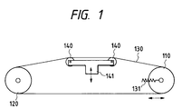
- Fig. 1 is a view which schematically shows the details of the conventional belt conveying mechanism as described above.
- A pair of
platen rollers 140 are rotatively supported by a roller supporting member 141. The roller supporting member is arranged to be movable in the vertical direction (up and down). Aconveying roller 120 is a driving roller driven by a driving mechanism (not shown). Meanwhile, aconveying roller 110 is a driven roller to rotate following the rotation of thedriving roller 120 through abelt 130. Theconveying roller 120 is fixed only to make its rotation possible. - On the other hand, the conveying
roller 110 is arranged to move in the direction to be further away from or closer to the conveyingroller 120, that is, it is made possible to shift and rotate only in the horizontal direction to the left and right in Fig. 1. Also, the conveyingroller 110 is biased by means of atension adjustment spring 131 in the direction that it is further away from theconveying roller 120. In this way, an appropriate tension is exerted on theconveying belt 130. - However, the belt conveying mechanism described above presents the following problems with respect to the gap adjustment required for an ink jet head serving as a printing head.
- In accordance with the structure described above, the circumferential length of the belt 130 (the total length of the belt) tends to change (the tension often changes) by the movement of the
platen rollers 140 if theplaten rollers 140 are caused to shift up and down in order to adjust the gap between the ink jet head and a printing medium. Here, however, the displacement of theadjustment spring 131 is only means for absorbing this change. Therefore, if such displacement becomes too great, the biasing force of thespring 131 is caused to increase, thus rather increasing the tension of theconveying belt 130 eventually. As a result, thebelt 130 is caused to crack often or break in some cases. - Also, in accordance with the structure represented in Fig. 1, the
conveying roller 110 on the upstream side is arranged to move horizontally. Therefore, it is difficult to parallel this roller with the conveyingroller 120 precisely. Also, there is a problem that it is difficult to continuously maintain the parallel condition once set as it is. In such a case, the tension given to the belt becomes uneven so that the printing medium may be allowed to meander or take some irregular posture. - Further, since the conveying
roller 110 is movably arranged as described above, it is required to arrange a pressure roller that presses the printing medium to the conveyingroller 110 to move following the movement of theconveying roller 110. Consequently, there is encountered a problem that the mechanism and others needed for the operation of these rollers also become more complicated. - The present invention is designed in consideration of the problems described above. It is an object of the invention to provide a printing apparatus capable of making the tension exerted on an endless conveying member substantially constant even when the conveying surface of the endless conveying member is displaced.
- It is another object of the present invention to provide a printing apparatus capable of conveying a printing medium in good condition at all times by preventing the endless conveying member from making any defective movement that may follow the gap adjustment or the like to be effectuated between the printing head and the endless conveying member.
- It is still another object of the present invention to provide a printing apparatus capable of making the tension exerted on an endless conveying member substantially constant even when changing the gap between the printing head and the conveying surface of the endless conveying member.
- It is a further object of the present invention to provide a printing apparatus capable of making the tension exerted on an endless conveying member substantially constant by suppressing the amount of expansion or contraction of the endless conveying member in its conveying direction even when changing the gap between the printing head and the conveying surface of the endless conveying member.
- It is still a further object of the present invention to provide a printing apparatus capable of making adjustment to cope with changes of thickness of a wide printing medium even when changing the gap between the printing head and the endless conveying member by suppressing the amount of expansion or contraction of the endless conveying member in the conveying direction to exert a substantially constant tension on the endless conveying member.
- It is still another object of the present invention to provide a printing apparatus capable of preventing an endless conveying member from meandering or taking any irregular posture in order to convey a printing medium in good condition by suppressing the amount of expansion or contraction of the endless conveying member in the conveying direction of the endless conveying member to exert a substantially constant tension on the endless conveying member even when changing the gap between the printing head and the conveying surface of the endless conveying member.
- It is still another object of the present invention to provide a printing apparatus capable of setting a desirable gap between the ink jet head and a printing medium for printing media of various thicknesses, while maintaining non-contacting state between them, even when changing the gap between the ink jet head and the conveying surface of the endless conveying member by suppressing the amount of expansion or contraction of the endless conveying member in its conveying direction to exert substantially constant tension on the endless conveying member.
- It is still another object of the present invention to provide a printing apparatus using a printing head to print on a printing medium being conveyed by means of an endless conveying member, comprising two roller members supporting the endless conveying member tensioned around them; a first displacing unit to displace the portion of the endless conveying member that faces the printing head in the direction different from the traveling direction of the endless conveying member; and a second displacing unit to displace the endless conveying member on the side opposite to the endless conveying member, which is displaced by means of the first displacing unit, in accordance with the displacement of the endless conveying member made by the first displacing unit.
- It is still another object of the present invention to provide a printing apparatus using a printing head to print on a printing medium, comprising a belt conveying mechanism to convey the printing medium by causing a belt to travel; a first pressure member to displace the belt in the direction different from the traveling direction of the belt; and a second pressure member elastically coupled to the pressing portion of the first pressure member to press the belt by the application of elasticity thus exerted.
- It is still another object of the present invention to provide a mechanism for conveying a printing medium and a printing apparatus using such mechanism for conveying a printing medium, being capable of minimizing the variation of tension exerted on a belt as a whole by arranging to change the elasticity of a second pressure member, such as rollers to press the belt, in accordance with the displacement of the belt made by a first pressure member such as platen rollers to press the belt.
- Fig. 1 is a side view which schematically shows the structure of a conveying unit in accordance with one conventional example of a printing apparatus.
- Fig. 2 is a cross-sectional view schematically showing a printing apparatus in accordance with the present invention.
- Figs. 3A, 3B, and 3C are views schematically illustrating the principle of structure embodying the present invention.
- Figs. 4A, 4B and 4C are views schematically showing the conventional structure as a comparative example in order to illustrate the principle of structure embodying the present invention.
- Fig. 5 is a side view which shows a conveying unit in accordance with a first embodiment of the present invention.
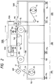
- Fig. 6 is a cross-sectional view which shows the conveying unit represented in Fig. 5.
- Fig. 7 is a top view which shows the conveying unit represented in Fig. 5.
- Fig. 8 is a side view which shows a state where the tension exerted on a conveying belt is released in the conveying unit represented in Fig. 5.
- Fig. 9 is a side view which shows a conveying unit in accordance with a second embodiment of the present invention.
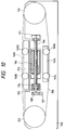
- Fig. 10 is a cross-sectional view which shows the conveying unit represented in Fig. 9.
- Fig. 11 is a top view which shows the conveying unit represented in Fig. 9.
- Fig. 12 is a front view which shows the conveying unit represented in Fig. 9.
- Figs. 13A and 13B are views which schematically show the linkage for the conveying unit represented in Fig. 9.
- Fig. 14 is a side view which shows a conveying unit in accordance with a third embodiment of the present invention.
- Hereinafter, with reference to the accompanying drawings, the detailed description will be made of the embodiments in accordance with the present invention.
- Fig. 2 shows a printing apparatus in accordance with a first embodiment of the present invention.
- Here, a
reference numeral 1 designates cloth prepared as a printing medium. Thecloth 1 is being fed out from the feedingroller 11 of afeeding unit 200 as the roller rotates, and wound up by a windingroller 21 through a conveyingroller 17 andintermediate roller 19 after it is conveyed substantially in the horizontal direction by means of a conveyingunit 100 arranged in the location facing aplaten unit 1000 subsequent to being conveyed throughintermediate rollers - The conveying
unit 100 is provided with conveyingrollers printing unit 1000 roughly in the conveying direction of thecloth 1; a conveyingbelt 130 prepared in an endless mode rotatively arranged between these rollers; and a plurality ofplaten rollers 140 to cause the conveyingbelt 130 to be developed and tensioned appropriately in a given range in order to regulate and improve the flatness of the printing surface of the cloth. Here, the conveyingbelt 130 used for the present embodiment is a metallic belt such as disclosed in Japanese Patent Laid-Open Application No. 5-212851, and as partially enlarged in Fig. 1 for representation, an adhesive layer (sheet) 133 is provided on the surface thereof. Then thecloth 1 is adhesively attached to the conveyingbelt 130 by means of the adhesive layer 133 and a fixingroller 150, thus securing its flatness at the time of printing. - In this respect, a
carriage 1010 is installed on theprinting unit 1000 movably in the direction perpendicular to the surface of Fig. 1 and Fig. 2. During the traveling period of thecarriage 1010, printing is performed by means of two ink jet heads installed on the carriage. - The
cloth 1, being conveyed in a state where its flatness is thus secured, is provided with a printing agent by means of theprinting unit 1000 while it is in the region between theplaten rollers 140, and then, peeled off from the conveyingbelt 130 or the adhesive layer in the location where the conveyingroller 120 is arranged. Hence it is being wound up by the windingroller 21, but on the way, a drying treatment is given by means of a dryingheater 600. The dryingheater 600 is effective particularly when a liquid is used as a printing agent. Here, as the dryingheater 600, it may be possible to adopt a device in such a mode as to blow hot air onto thecloth 1 or radiate infrared rays, among other appropriate means. Also, in a position to which theprinting unit 1000 can slide, ahead shading station 1600 is arranged for theink jet head 1010 in order to correct its density unevenness. - With the structure described above, the
feed roller 11, the windingroller 21, the conveyingrollers frame 113 and aside board 103 integrally arranged by a frame welding structure, which serve as the structural body of the textile printing apparatus. In a plurality of specific locations on theframe 113,level pads 114 are provided in order to adjust the leveling of the apparatus in the horizontal and height directions with respect to the surface of the installation floor. - Also, the
printing unit 1000 is installed movably in the horizontal direction to enhance the operativity of maintenance work or the like such as replacement of belts. - Now, before describing some of the embodiments of the present invention, the conception with which to structure such embodiments will be described with reference to Figs. 3A to 3C and Figs. 4A to 4C.
- Figs. 3A to 3C are views which illustrate the structural concept of the present embodiments, in which an
upper platen roller 140U and alower platen roller 140L are arranged, and a drivingroller 120 and a drivenroller 110 are fixed to the printing apparatus main body so that the distance between them is constantly maintained (1,160 mm). Also, the upper andlower platen rollers lower platen rollers lower platen rollers - On the other hand, Figs. 4A to 4C illustrate the comparative example whose structure corresponds to the one in Fig. 1, in which no platen rollers are arranged on the lower side: only the
upper platen rollers 140 are provided. Each of the other constituents is the same as the one shown in Figs. 3A to 3C. Then, while the state illustrated in Fig. 4B is made standard, Fig. 4A shows a state where theplaten rollers 140 are displaced downward by 5 mm, and Fig. 4C illustrates a state where theplaten rollers 140 are displaced upward by 5 mm. - As clear from Figs. 3A to 3C and Figs. 4A to 4C, whereas the circumferential length L of the belt changes only by 0.12 mm in either upper and lower displacements of the
platen rollers platen rollers 140, and 0.46 mm by the upper displacement thereof as in Figs. 4A to 4C where the comparative example is illustrated. - As described above, if the platen rollers are arranged up and down, changes in the circumferential length L of the belt resulting from the gap adjustment, that is, changes in the tensions of the belt, are made comparatively small. Therefore, it is possible to make the degrees of displacement smaller for the mechanism to absorb such changes of tension resulting from the tension adjustment. In other words, there is no need for any arrangement to make the conveying
roller 110 movable on the driven side as in the conventional structure, and also, there is no need for any arrangement to cope with comparatively large changes in the tension by the provision of the tension adjustment spring that gives biasing force to such roller as represented in Fig. 2, for example. - Fig. 5, Fig. 6, and Fig. 7 are views showing the conveying unit in accordance with a first embodiment of the present invention. These are a side view, a view of this side observed from the back side, and a top view of the present embodiment, respectively.
- The axes of conveying
rollers side board 146. Therefore, the distance between the rollers is made constant (1,160 mm) as described earlier. At the same time, both rollers are adjusted in advance to be in parallel to each other. Also, theplaten rollers boards rollers - On the outer side of both side boards 146 (only one of them is shown) of the conveying unit, a mechanism is arranged to cause the upper and
lower platen rollers - In other words, to a part of the upper supporting
board 141U, therod 143R of anair cylinder 143 is fixed, while thecylinder 143 main body is fixed to the lower supportingboard 141L. In this way, the lower supportingboard 141L is relatively biased downward. In this respect, the biasing force exerted by means of thiscylinder 143 is not exercised usually. Only when the biasing force exerted by aspring 142 is not strong enough, thecylinder 143 is used in combination to provide a sufficient biasing. Also, to both ends of the upper supportingboard 141U, one end of alinear guide shaft 145 is fixed, while the lower supportingboard 141L is arranged to slidably engage with thelinear guide shaft 145 through the holes formed on both ends thereof. Then thespring 142 is arranged in a mode that it winds around theshaft 145 between the upper supportingboard 141U and the lower supportingboard 141L. By means of thisspring 142, the lower supportingboard 141L is relatively biased downward. - With the structure described above, when the upper supporting
board 141U is displaced upward or downward by means of a mechanism which will be described later, the lower supporting board 114L biased by means of thespring 142 is interlocked with the upper supportingboard 141U to be displaced accordingly so that it is displaced upward or downward while keeping the distance constantly between them substantially. - Substantially in the central portion (see Fig. 7) of the conveying unit, a mechanism is arranged to displace the
platen roller 140U upward or downward as shown mainly in Fig. 6. - A ball
screw supporting board 153 is fixed to theside board 146. Meanwhile, aball screw 151 engages with the ballscrew supporting board 153 through anangular bearing 154. At the same time, the ball screw is fixed to aworm wheel 156. Theangular bearing 154 regulates the backlashes of theball screw 151 in the thrust and radial directions. The other end of theball screw 151 engages with aball screw nut 152 fixed to a fixingplate 150 of the upper supporting board, which connects the upperplaten supporting boards 141U arranged respectively on both side portions. - With the structure described above, when a
worm gear 157 is caused to rotate by means of a motor (not shown), theball screw 151 coupled to theworm wheel 156 rotates. In accordance with the rotational direction thereof, the fixingplate 150 of the upper supporting board is caused to move so that theupper platen roller 140U shifts upward or downward. - Fig. 8 is a view which shows a state that the tension of the conveying belt (not shown in Fig. 8) is released in the conveying unit of the first embodiment described above.
- In other words, the supporting
board 141L for the lower platen rollers is raised by means of thecylinder 143 in this released state. Also, it is possible to materialize lowering the supportingboard 141U for the upper platen rollers by causing theworm wheel 156 to rotate. - Fig. 9 to Fig. 12 are views which illustrate the structure of a conveying unit in accordance with another embodiment of the present invention. Fig. 9 is a side view; Fig. 10 is a cross-sectional view; Fig. 11 is a top view; and Fig. 12 is a front view thereof observed from the conveying
roller 120 side. - In accordance with the present embodiment, the mechanism required for raising and lowering the supporting
board 141U for the upper platen rollers is structured by use of parallel links. As shown in Fig. 9, afixed link 163 is fixed to aside board 146. To one end of the fixedlink 163, the central portion of amovable link 162 is rotatively mounted. One end of thismovable link 162 is rotatively mounted on the supportingboard 141U for the upper platen rollers, while the other end is rotatively mounted on aslider 165. Likewise, one end of themovable link 161 is rotatively mounted on the supportingboard 141U for the upper platen rollers, while the other end is rotatively mounted on theslider 165. Figs. 13A and 13B show this linkage schematically. - The
slider 165 is guided by means of a linear guide bearing 170 andlinear guide shaft 169 as shown mainly in Fig. 10, thus being arranged to shift in the left and right directions in Fig. 10. Meanwhile, on thisslider 165, aball nut 173 that engages with aball screw 166 is mounted so that theslider 165 is shiftable in the left and right directions when the ball screw 160 rotates. In other words, both ends of theball screw 166 are respectively installed on the supportingboards side board 146. On one end of the ball screw, aworm wheel 168 is mounted to engage with aworm gear 167. Theworm gear 167 rotates manually through ahandle 173 or by use of amotor 174. - The shift of the
slider 165 as described above is transformed into the vertical shift of the supportingboard 141U for the upper platen rollers through the aforesaid linkage. - In this respect, the gap adjustment described above may be possible by controlling the rotation of the worm gear in accordance with the gap to be sensed by the
gap sensor 144 shown in Fig. 5. - Fig. 14 is a side view which shows a conveying unit in accordance with a third embodiment of the present invention.
- Conveying
rollers side board 146 in such a manner that the axes thereof are made parallel to each other. At the same time, it is structured so that theroller 110 on the driven side is caused to move further away from or closer to theroller 120 on the driving side, while maintaining the parallel condition between them, in order to conduct the initial setting of thebelt 130 or the like. - Each of three
platen rollers boards 201, which face each other, so that each of the rollers is in parallel to the conveyingrollers platen rollers 140U mounted on the supportingboard 201 are arranged in such a manner that the conveying surface of thebelt 130, being guided by theseplaten rollers 140U, is made extremely flat so as to preferably serve as the printing area for a printing medium. - The pair of the supporting
boards 201 are arranged to move vertically when an operator rotates ahandle 202 to cause threadedshafts 206 to rotate, thus allowing each tooth portion provided for the respective shaft to engage with each tooth unit (not shown) mounted on the supportingboard 201 through therotational shaft 203, gears 204 and 205. In this respect,shafts 207 are the members to support theside board 146 to apart 208 of the housing of the printing apparatus. - With the structure described above, when the operator rotates the
handle 202, theplaten rollers belt 130, which is guided by the threeplaten rollers 140U to serve as the printing area for a printing medium, is made movable further away from or closer to the ink jet head mounted on thecarriage 1010 that faces such conveying surface of the belt. Therefore, it is possible to change the gap between the surface of the belt and the ink jet head while minimizing the changes in the circumferential length of the belt that may occur following the vertical movement of theplaten rollers - In this respect, the description has been made of a structure where the
handle 202 is rotated by the operator, but it is possible to obtain the same effect by the vertical movement of the supportingboard 201 with the rotation of the threadedshafts 206 by the application of driving force generated by a motor or the like. - Further, it is possible to automatically print on various printing media by arranging a structure to control the vertical movement of the supporting
board 201 with the rotation of the threadedshafts 206 by the application of driving force of a motor or the like in accordance with the thickness of a printing medium to be used, which is detected in advance and guided to the printing area. - In accordance with each of the embodiments described above, a printing apparatus for printing by use of a printing head on a printing medium to be conveyed by means of an endless conveying
member 130 is provided with tworollers - Further, it is possible to make the tension exerted on the endless conveying member substantially constant even when changing the gap between the printing head and the conveying surface of the endless conveying member.
- Further, it is possible to make the tension exerted on the endless conveying member substantially constant by suppressing the amount of expansion or contraction of the endless conveying member in the conveying direction even when changing the gap between the printing head and the conveying surface of the endless conveying member.
- Further, it is possible to cope with the changes in thicknesses of wide printing media by suppressing the amount of expansion or contraction of the endless conveying member in the conveying direction so as to exert a substantially constant tension on the endless conveying member even when changing the gap between the printing head and the conveying surface of the endless conveying member.
- Further, it is possible to prevent the endless conveying member from meandering or taking defective posture in order to convey a printing medium in good condition by suppressing the amount of expansion or contraction of the endless conveying member in the conveying direction so as to exert a substantially constant tension on the endless conveying member even when changing the gap between the printing head and the conveying surface of the endless conveying member.
- Further, it is possible to set the gap between the ink jet head and a printing medium preferably for printing media of various thicknesses, while maintaining non-contacting state between them, by suppressing the amount of expansion or contraction of the endless conveying member in the conveying direction so as to exert a substantially constant tension on the endless conveying member even when changing the gap between the printing head and the conveying surface of the endless conveying member.
- Particularly, even for a large printing head that weighs heavily and needs a complicated mechanism to cause the head to move further away from or closer to the endless conveying side (platen side), it is possible to obtain the aforesaid effect of the conveying mechanism to adjust the gap between the printing head and a printing medium (head gap) by the application of displacement made on the endless conveying side (platen side). Here, it is also necessary for the endless conveying member to maintain the surface of a specific area in the printing region (because such maintenance is particularly important in the present embodiments where printing-should be performed with the head and the printing medium being in non-contacting state). Therefore, the material used for the conveying member should not be too soft and easily deformed. A metallic belt or a rubber belt that is not easy to be deformed elastically should be employed. Therefore, in accordance with each of the embodiments described above, it is arranged so that the amount of expansion or contraction of the belt material is small when the head gap is adjusted, thus making it easier to select a belt material that is preferably used for the maintenance of the surface that provides a specific area in the printing region.
- In this way, it is possible to obtain a printing apparatus capable of performing the full color printing in a higher precision on a wider printing area using various kinds of printing media, such as paper, cloth, or plate having a thickness of several cm, by use of a full line ink jet printing head that is practically used as a printing head at present, which discharges ink each in black, yellow, cyan, and magenta in more than 360 dpi.
- Now, the description will be made of the entire process of ink jet textile printing performed by use of the apparatus in accordance with the embodiments described above.
- After having completed the ink jet textile printing by use of the ink jet recording apparatus described above, the printed cloth is dried (including natural drying). Subsequently, the dyes on fiber texture are diffused, and then, a step is taken to cause the dyes to react and fix them on the cloth. In this step, it is possible to obtain both a sufficient coloring and durability by the fixation of dyes.
- For the diffusion and reactive fixation, conventionally known steps are adoptable. For example, the steaming method will do. Here, in this case, it may be possible to give alkali treatment to the cloth in advance before the printing process is executed.
- After that, in the postprocesses, non-reactive dyes and substances used for the preprocesses are removed. Lastly, then, the recording is completed through the adjustment finish, such as defect correction, ironing finish, and other related steps.
- Now, particularly for the cloth used for the ink jet printing, the following properties are required:
- (1) The color of ink should come out in a sufficient density.
- (2) The degree of exhaustion of ink should be high.
- (3) Ink should dries quickly on the cloth.
- (4) Ink should not blur irregularly on the cloth.
- (5) The cloth should be easy to be conveyed in the apparatus.
- In order to satisfy these properties, it is possible for the present invention to preprocess the cloth as required. For example, in accordance with Japanese Patent Laid-Open Application No. 62-53492, there are disclosed cloth provided with a layer for receiving ink. Also, in Japanese Patent Publication No. 3-46589, it is proposed to provide the cloth in which reduction preventive agent or alkaline substance is contained. As an example of such preprocess, it is possible to cite a treatment, which is made to enable these cloths to contain a substance selected from among alkaline substance, water soluble polymer, synthetic polymer, water soluble metallic salt, urea, and thiourea.
- For the alkaline substance, it is possible to cite, for example, sodium hydroxide, potassium hydroxide, or other sodium alkaline metals, mono-, di-, tri-ethanol amine or other amine group, sodium carbonate, sodium bicarbonate, or other carbonates, alkaline metallic bicarbonate salt or the like. Further, there can be cited organic metallic salt such as calcium acetate, barium acetate, or ammonia and ammonia compound or the like. Also, it is possible to use the trichloro natrium acetate or the like that is transformed into alkaline substance by the application of steaming and drying heat. Particularly, preference is given to natrium carbonate and natrium bicarbonate as an alkaline substance, which is usable as a dye color of reactive pigment.
- As water soluble polymer, there can be cited, for example, starch such as corn, wheat, cellulose substance such as carboxymethyl cellulose, methyl cellulose, hydroxyethyl cellulose, polysaccharide such as natrium alginic acid, arabian rubber, loquasweet bean rubber, tragacanth rubber, guam rubber, and tamarind seed, protein substance such as gelatin, casein, and water soluble natural polymer such as tannic substance and lignin substance.
- Also, as synthetic polymer, there can be cited, for example, polyvinyl alcoholic compound, polyethylene oxide compound, alkali acid water soluble polymer, maleic anhydride water soluble polymer or the like. Of these substances, it is preferable to use polysaccharide polymer or cellulose polymer.
- As water soluble metallic salt, there can be cited, for example, alkali metals or a compound of pH4 to 10, which forms typical ionic crystals, such as halogenous compound of alkaline earth metals. As typical examples of such compounds, there can be cited NaCl, Na₂SO₄, KCl and CH₃COONa, or the like. Also, as alkaline earth metals, CaCl₂ and MgCl₂ or the like. Of these substances, salt group such as Na, K and Ca are preferable.
- In the preprocesses, the methods for enabling cloth to contain those substances and others are not particularly limited. It may be possible to adopt a usually performed dipping method, a padding method, a coating method, or a spraying method, among others.
- Further, the textile printing ink, which is applicable to cloth for use of ink jet printing, is such as just adhering to the cloths when it is applied to printing on the cloths. Therefore, it is preferable to execute a fixing process so that the color pigments in ink such as dyes should be fixed to the cloths. For a fixing process of the kind, any one of known methods is usable. For example, a steaming method, an HT steaming method, or a thermofixing method may be cited. If no alkali treatment is given to them in advance, there can be cited an alkali pad steaming method, an alkali blotch steaming method, an alkali shock method, an alkali cold fixing method, among others. Also, for the fixing process, there are those which include a reaction process or do not include it depending on the dyes to be used. Among those which do not include this process, there are some examples in which the dyes are contained in the cloths and do not allow them to be removed physically. Also, as ink, it is possible to use any one of them appropriately if only a required pigment is contained. Also, it may be possible to use the ink containing colors, not necessarily dyes. Further, in order to remove the non-reactive dyes and the substances used in the preprocess, rinsing may be applied in accordance with the conventionally know method after having executed the reactive fixation as described above. In this respect, it is preferable to perform the conventional fixing process together when exercising the rinsing treatment.
- The printed articles that have been given the post processes as described above are cut in a desired size. Each of the pieces thus cut is processed in order to make it a final product, such as by means of sewing, bonding, welding, or the like, thus obtaining one-piece, dress, necktie, swim suit or other clothing, or bed cover, sofa cover, handkerchief, curtain, or the like. The method for processing cloths to make them clothing or other daily necessities by means of sawing and others is disclosed in many books publicly known, such as "Modern Netting and Machining Manual (Published by Seni Journal Inc.)" and "Monthly Magazine, Souen (Published by Bunka Shuppan Kyoku)", among others.
- In this respect, as a printing medium, there can be cited cloths, wall cloths, embroidery threads, wall papers, paper sheets, OHP films, anodized aluminum plates or various others to which a given liquid is applicable by use of the ink jet technologies. Here, the cloths include all the textiles, nonwoven textiles, and other cloths irrespective of materials, weaving and netting methods.
- For the present invention, it is possible to employ not only the aforesaid ink jet printing method, but also various printing methods. With the adoption of an ink jet printing method to embody the present invention, significant effects are obtainable. Of the ink jet printing methods, it is possible to demonstrate particularly excellent effects by the application of a method having means for generating thermal energy to be utilized as energy for discharging ink, which is capable of changing states of ink when the thermal energy is applied. In other words, the adoption of printing head and apparatus using the bubble jet method advocated by Canon Inc. contributes to obtaining still better results. With the application of a method of the kind, printing is possible in a higher density and precision.
- Regarding the typical structure and operational principle of such method, it is preferable to adopt those which can be implemented using the fundamental principle disclosed in the specifications of U.S. Patent Nos. 4,723,129 and 4,740,796. This method is applicable to the so-called on-demand type printing system and a continuous type printing system as well. Particularly, however, the method is suitable for the on-demand type because the principle is such that at least one driving signal, which provides a rapid temperature rise beyond a departure from nucleation boiling point in response to printing information, is applicable to an electrothermal transducer disposed on a liquid (ink) retaining sheet or liquid passage whereby to cause the electrothermal transducer to generate thermal energy to produce film boiling on the thermoactive portion of printing head, thus effectively leading to the resultant formation of a bubble in the liquid (ink) one to one for each of the driving signals. By the development and contraction of the bubble, the liquid (ink) is discharged through a discharging port to produce at least one droplet. The driving signal is more preferably in the form of pulses because the development and contraction of the bubble can be effectuated instantaneously, and, therefore, the liquid (ink) is discharged with quick response. The driving signal in the form of pulses is preferably such as disclosed in the specifications of U.S. Patent Nos. 4,463,359 and 4,345,262. In this respect, the temperature increasing rate of the heating surface is preferably such as disclosed in the specification of U.S. Patent No. 4,313,124 for an excellent printing in a better condition.
- In addition, the structure of the printing head may be as shown in each of the above-mentioned specifications wherein the structure is arranged to combine the discharging ports, liquid passages, and the electrothermal transducers (linear type liquid passages or right-angled liquid passages). Besides, the structure such as disclosed in the specifications of U.S. Patent Nos. 4,558,333 and 4,459,600 wherein the thermal activation portions are arranged in a curved area is also included in the present invention. In addition, the present invention is effectively applicable to the structure disclosed in Japanese Patent Laid-Open Application No. 59-123670 wherein a common slit is used as the discharging ports for plural electrothermal transducers, and to the structure disclosed in Japanese Patent Laid-Open Application No. 59-138461 wherein an aperture for absorbing pressure wave of the thermal energy is formed corresponding to the discharge ports. In other words, irrespective of the modes of printing heads, it is possible to print reliably and efficiently in accordance with the present invention.
- In addition, it is of course possible to structure the printing head in accordance with the mode of a printing apparatus. With respect to the mode of the so-called line printer, it should be good enough if only the printing head is structured so that its discharge ports are arranged over an area corresponding to the width of a printing medium. Also, for the printing head of a serial type as exemplified above, the present invention is effectively applicable to a printing head fixed to the apparats main body or to an exchangeable chip type, which can be electrically connected with the apparatus main body and ink is supplied from the apparatus main body to the head when it is installed in the apparatus main body, or to the printing head of a cartridge type in which an ink tank is formed together with the printing head itself.
- Also, for the present invention, it is preferable to additionally provide a printing head with recovery means and preliminarily auxiliary means as constituents of the printing apparatus because these additional means will contribute to making the effectiveness of the present invention more stabilized. To cite them specifically, these are capping means for the printing head, cleaning means, compression or suction means, preliminary heating means using electrothermal transducing elements or heating elements other than these transducing elements or combination of both elements, and predischarge means for executing discharges other than those for printing.
- Furthermore, in the embodiments of the present invention described above, while the ink has been described as liquid, it may be an ink material which is solidified below the room temperature but liquefied at the room temperature. Since the ink is controlled within the temperature not lower than 30°C and not higher than 70°C to stabilize its viscosity for the provision of the stable discharge in general for an ink jet method, the ink may be such as to be liquefied when the applicable printing signals are given. In addition, it may be possible to adopt the use of ink having a nature of being liquefied only by the application of heat so as to positively prevent the temperature from rising due to the thermal energy by use of such energy as an energy to be consumed for changing states of ink from solid to liquid, or to prevent ink from being evaporated by use of the ink which will be solidified when left intact. In any case, it may be possible to apply to the present invention such ink having a nature to be liquified only by the application of thermal energy, such as the ink, which is capable of being discharged as ink liquid by enabling itself to be liquefied when the thermal energy is applied in accordance with printing signals, and the ink, which will have already begun solidifying itself by the time it reaches a printing medium. In this case, it may be possible to retain ink in the form of liquid or solid in the recesses or through holes of a porous sheet such as disclosed in Japanese Patent Laid-Open Application No. 54-56847 or 60-71260 in order to enable ink to face the electrothermal transducers. In the present invention, the most effective method adoptable for the various kinds of ink referred to above is the one which is capable of implementing film boiling as described above.
- Moreover, as the mode of the present invention, it may be possible to adopt a copying apparatus combined with a reader or the like in addition to the image output terminal for a computer, or other information processing apparatus.
- As clear from the above description, the first pressure means such as the platen rollers presses the belt to displace it, and following this displacement, the elasticity of the second pressure member such as rollers to press the belt likewise changes in accordance with the present invention. Therefore, it is possible to make the changes in the tension exerted on the belt small as a whole.
- A printing apparatus for printing by use of a printing head on a printing medium conveyed by means of an endless conveying member comprises two roller members to support an endless conveying member tensioned around them, a first displacing unit to displace the endless conveying member in the direction different from the traveling direction of the endless conveying member, this first displacing unit being arranged to displace the portion of the endless conveying member, which faces the printing head, and a second displacing unit to displace the endless conveying member on the side opposite to the endless conveying member displaced by the first displacing unit in accordance with the displacement of the endless conveying member made by the first displacing unit. With the structure thus arranged, it is possible to make the tension exerted on the conveying belt extremely small as a whole. Hence there is no need for the provision of any particular elements to cope with comparatively large changes in the tension acting on the conveying belt, that may otherwise result in making the apparatus larger. Also, the gap between the printing head and the conveying surface of the conveying member is maintained relaibly for the execution of printing in good condition.
Claims (15)
- A printing apparatus for printing by use of a printing head on a printing medium conveyed by means of an endless conveying member, including the following:
two roller members to support an endless conveying member tensioned around them;
a first displacing unit to displace said endless conveying member in the direction different from the traveling direction of said endless conveying member, said first displacing unit displacing the portion of said endless conveying member facing the printing head; and
a second displacing unit to displace said endless conveying member on the side opposite to said endless conveying member displaced by said first displacing unit in accordance with the displacement of said endless conveying member made by said first displacing unit. - A printing apparatus according to Claim 1, wherein said first displacing unit and said second displacing unit are connected elastically.
- A printing apparatus according to Claim 1, wherein said first displacing unit and said second displacing unit are connected by means of board member.
- A printing apparatus according to Claim 1, wherein said printing head is an ink jet printing head for discharging ink from ink discharge ports.
- A printing apparatus according to Claim 1, wherein said printing head is an ink jet printing head provided with electrothermal transducing elements to discharge ink from ink discharge ports by thermal energy generated by said electrothermal transducing elements.
- A printing apparatus for printing on a printing medium by use of a printing head, including the following:
a belt conveying mechanism for conveying said printing medium by causing a belt to travel;
a first pressure means for pressing said belt to displace said belt in the direction different from said traveling direction; and
a second pressure means elastically connected with the pressing portion of said first pressure means to press said belt by said elasticity. - A printing apparatus according to Claim 6, wherein said first pressure means makes displacement to adjust the gap between said printing head and a printing medium conveyed by said belt.
- A printing apparatus according to Claim 6, wherein said pressing portion of said first pressure means and said second pressure means are roller type members.
- A printing apparatus according to Claim 6, wherein said roller type members are a plurality of rollers, respectively.
- A printing apparatus according to Claim 6, wherein said printing medium is cloth.
- A printing apparatus according to Claim 6, wherein said printing head is to print by discharging ink.
- A printing apparatus according to Claim 7, wherein said printing head is to print by discharging ink.
- A printing apparatus according to Claim 8, wherein said printing head is to print by discharging ink.
- A printing apparatus according to Claim 9, wherein said printing head is to print by discharging ink.
- A printing apparatus according to Claim 10, wherein said printing head is to print by discharging ink.
Applications Claiming Priority (4)
| Application Number | Priority Date | Filing Date | Title |
|---|---|---|---|
| JP244421/94 | 1994-10-07 | ||
| JP24442194 | 1994-10-07 | ||
| JP7249967A JPH08156353A (en) | 1994-10-07 | 1995-09-27 | Printing apparatus |
| JP249967/95 | 1995-09-27 |
Publications (2)
| Publication Number | Publication Date |
|---|---|
| EP0705707A1 true EP0705707A1 (en) | 1996-04-10 |
| EP0705707B1 EP0705707B1 (en) | 1999-03-24 |
Family
ID=26536732
Family Applications (1)
| Application Number | Title | Priority Date | Filing Date |
|---|---|---|---|
| EP95115802A Expired - Lifetime EP0705707B1 (en) | 1994-10-07 | 1995-10-06 | Printing apparatus |
Country Status (6)
| Country | Link |
|---|---|
| US (1) | US5854643A (en) |
| EP (1) | EP0705707B1 (en) |
| JP (1) | JPH08156353A (en) |
| KR (1) | KR100202725B1 (en) |
| CN (1) | CN1060116C (en) |
| DE (1) | DE69508515T2 (en) |
Cited By (13)
| Publication number | Priority date | Publication date | Assignee | Title |
|---|---|---|---|---|
| WO1999004080A1 (en) * | 1997-07-16 | 1999-01-28 | Minnesota Mining And Manufacturing Company | Method of continuous tone imaging to provide an imaged high loft mat product |
| GB2354975A (en) * | 1999-10-05 | 2001-04-11 | Hewlett Packard Co | Vacuum belt media support for ink-jet printer wherein the belt is supported above a platen surface by a series of rollers to reduce belt friction drag |
| EP1164027A3 (en) * | 2000-02-23 | 2003-08-13 | Agfa-Gevaert | Ink jet printer with device for avoiding undesirable belt movement |
| EP1518700A1 (en) * | 2003-09-25 | 2005-03-30 | Konica Minolta Holdings, Inc. | Injet recording apparatus |
| EP1529648A1 (en) * | 2003-11-08 | 2005-05-11 | Atlantic ZeiserGmbH | Method for manufacturing information supports, e.g. cards, and installation for its realization |
| EP1580011A1 (en) * | 2004-03-26 | 2005-09-28 | Brother Kogyo Kabushiki Kaisha | Printer with print gap adjustment mechanism |
| EP1431925A3 (en) * | 2002-12-19 | 2006-06-07 | Pitney Bowes Inc. | Transport mechanism for a mailing machine and method to register a mail piece in a mailing machine |
| CN102582214A (en) * | 2012-03-20 | 2012-07-18 | 丹东金丸集团有限公司 | Spray nozzle combination device of nanometer material direct-to-plate |
| EP2172343A3 (en) * | 2008-10-01 | 2013-03-20 | Miyakoshi Printing Machinery Co., Ltd. | Textile printing method and apparatus |
| EP2910381A1 (en) * | 2014-02-25 | 2015-08-26 | Seiko Epson Corporation | Liquid discharge device and media pretreatment method |
| EP3489022A1 (en) * | 2017-11-22 | 2019-05-29 | Frama AG | Device for printing on mail items fed individually to a printing unit |
| CN111923609A (en) * | 2020-08-20 | 2020-11-13 | 吕学兴 | Novel stationery label production facility |
| NL2032611B1 (en) * | 2022-07-27 | 2024-02-05 | Canon Kk | A printer with a definition roller for an endless belt |
Families Citing this family (51)
| Publication number | Priority date | Publication date | Assignee | Title |
|---|---|---|---|---|
| US6386662B1 (en) * | 1997-02-03 | 2002-05-14 | Citicorp Development Center, Inc. | Wide mouth banking depositor |
| US6652054B2 (en) | 2000-02-01 | 2003-11-25 | Aprion Digital Ltd. | Table and a motion unit for adjusting the height thereof |
| US6588954B2 (en) * | 2000-02-23 | 2003-07-08 | Agfa-Gevaert | Ink jet printer equipped for avoiding undesired belt movement |
| JP4278885B2 (en) * | 2000-05-25 | 2009-06-17 | 富士フイルム株式会社 | Inkjet printer |
| US6755518B2 (en) * | 2001-08-30 | 2004-06-29 | L&P Property Management Company | Method and apparatus for ink jet printing on rigid panels |
| US6523921B2 (en) | 2000-08-30 | 2003-02-25 | L&P Property Management | Method and apparatus for printing on rigid panels and other contoured or textured surfaces |
| US6406110B1 (en) | 2000-09-01 | 2002-06-18 | Lexmark International, Inc | Mechanism to automate adjustment of printhead-to-print medium gap spacing on an imaging apparatus |
| IT1316139B1 (en) * | 2000-09-15 | 2003-03-28 | Durst Phototechnik Ag | INK-JET PRINTING DEVICE. |
| US6561607B1 (en) * | 2000-10-05 | 2003-05-13 | Eastman Kodak Company | Apparatus and method for maintaining a substantially constant closely spaced working distance between an inkjet printhead and a printing receiver |
| AU1265202A (en) * | 2000-10-23 | 2002-05-06 | Aprion Digital Ltd | Apparatus and method for protecting printing heads |
| JP2002283636A (en) * | 2001-03-27 | 2002-10-03 | Sony Corp | Printer |
| US20030116041A1 (en) * | 2001-12-20 | 2003-06-26 | Delaware Capital Formation, Inc. | Moveable idler carriage for support of a web in relation to an array of inkjet printing devices |
| US6840617B2 (en) * | 2002-04-02 | 2005-01-11 | Lexmark International, Inc. | Mid-frame for an imaging apparatus |
| US7118103B2 (en) * | 2003-04-14 | 2006-10-10 | Heidelberger Druckmaschinen Ag | Device for conveying sheets through a printing machine |
| JP2005014343A (en) * | 2003-06-25 | 2005-01-20 | Roland Dg Corp | Inkjet printer |
| JP4321151B2 (en) * | 2003-07-23 | 2009-08-26 | 沖電気工業株式会社 | Printer |
| JP4539399B2 (en) * | 2004-03-26 | 2010-09-08 | ブラザー工業株式会社 | Recording device |
| US7422386B2 (en) * | 2004-07-07 | 2008-09-09 | Roland Dg Corporation | Image creation and cutting apparatus |
| US8493628B2 (en) * | 2005-04-21 | 2013-07-23 | The Boeing Company | Reproduction of images onto surfaces |
| US20060238815A1 (en) * | 2005-04-21 | 2006-10-26 | The Boeing Company | Systems and methods of reproducing images onto surfaces |
| KR20060123842A (en) * | 2005-05-30 | 2006-12-05 | 삼성전자주식회사 | Ink injection apparatus, image forming apparatus having the same and method for forming image |
| KR100789230B1 (en) | 2006-05-17 | 2008-01-02 | 주식회사 디지아이 | Control apparatus of fabric thrust force with a plotter |
| US20090160889A1 (en) * | 2007-12-24 | 2009-06-25 | Pitney Bowes Inc. | Method and apparatus for printing on variable thickness print media |
| JP5009817B2 (en) * | 2008-01-08 | 2012-08-22 | 株式会社リコー | Image forming apparatus |
| EP2106916B1 (en) * | 2008-03-31 | 2011-05-04 | Dainippon Screen Mfg., Co., Ltd. | Image recording apparatus |
| JP5193738B2 (en) * | 2008-08-15 | 2013-05-08 | 理想科学工業株式会社 | Inkjet recording device |
| JP5274977B2 (en) * | 2008-10-24 | 2013-08-28 | 株式会社ミヤコシ | Inkjet recording device |
| JP5384215B2 (en) * | 2009-06-16 | 2014-01-08 | 株式会社ミマキエンジニアリング | Printer device |
| JP5568333B2 (en) * | 2010-02-24 | 2014-08-06 | 理想科学工業株式会社 | Image recording device |
| JP5646866B2 (en) * | 2010-03-31 | 2014-12-24 | キヤノン株式会社 | Medium transport device |
| CN101973166A (en) * | 2010-08-18 | 2011-02-16 | 温州品正电器有限公司 | Cloth printer |
| US9044928B2 (en) * | 2012-04-12 | 2015-06-02 | R.R. Donnelley & Sons Company | Mailing lines and related methods |
| US9365061B2 (en) | 2014-02-11 | 2016-06-14 | Electronics For Imaging, Inc. | External table height adjustment for printer systems |
| JP5762585B1 (en) * | 2014-02-27 | 2015-08-12 | 三菱重工印刷紙工機械株式会社 | Printing device |
| JP6364989B2 (en) * | 2014-06-18 | 2018-08-01 | セイコーエプソン株式会社 | Recording device |
| CN104139616B (en) * | 2014-08-08 | 2016-04-13 | 湖州巧布师数码科技有限公司 | A kind of conveyer for wide cut digit printing terylene wall paper |
| JP2016037682A (en) * | 2014-08-08 | 2016-03-22 | 株式会社ミマキエンジニアリング | Textile printer |
| JP6582624B2 (en) * | 2014-09-08 | 2019-10-02 | セイコーエプソン株式会社 | Recording device |
| JP6701899B2 (en) * | 2016-04-05 | 2020-05-27 | セイコーエプソン株式会社 | Liquid ejecting apparatus and medium pressing method |
| CN107458081A (en) * | 2017-09-15 | 2017-12-12 | 湖州博润实业有限公司 | A kind of printing in textiles work machine |
| CN107471841A (en) * | 2017-09-15 | 2017-12-15 | 湖州博润实业有限公司 | A kind of textile full-automatic printing device |
| CN107620180B (en) * | 2017-11-02 | 2020-04-24 | 界首市永顺服饰有限公司 | Cloth printing and dyeing device for clothing production |
| CN108044923B (en) * | 2017-12-20 | 2023-12-19 | 常州丰盛光电科技股份有限公司 | Composite roller mould with replaceable surface structure and manufacturing process thereof |
| KR102193013B1 (en) * | 2018-06-22 | 2020-12-18 | 김동철 | Foil printing method using uv ink printer |
| CN108859402A (en) * | 2018-06-28 | 2018-11-23 | 湖州新天地印刷有限公司 | A kind of pressing device of paper tube cardboard environmental printing |
| JP7119756B2 (en) * | 2018-08-21 | 2022-08-17 | コニカミノルタ株式会社 | Textile inkjet printer |
| CN109177527A (en) * | 2018-08-23 | 2019-01-11 | 合肥海闻自动化设备有限公司 | Flat-panel printer destatics system |
| JP7309402B2 (en) * | 2019-03-26 | 2023-07-18 | 理想科学工業株式会社 | image forming device |
| JP7383950B2 (en) | 2019-09-20 | 2023-11-21 | コニカミノルタ株式会社 | image forming device |
| WO2021066832A1 (en) * | 2019-10-03 | 2021-04-08 | Hewlett-Packard Development Company, L.P. | Printhead to print medium spacing adjusting system |
| CN112208196A (en) * | 2020-09-16 | 2021-01-12 | 马鞍山虹润彩印有限责任公司 | Green's food packaging film printing special printing mechanism |
Citations (18)
| Publication number | Priority date | Publication date | Assignee | Title |
|---|---|---|---|---|
| JPS5456847A (en) | 1977-10-14 | 1979-05-08 | Canon Inc | Medium for thermo transfer recording |
| US4207579A (en) * | 1979-01-08 | 1980-06-10 | The Mead Corporation | Reciprocating paper handling apparatus for use in an ink jet copier |
| US4313124A (en) | 1979-05-18 | 1982-01-26 | Canon Kabushiki Kaisha | Liquid jet recording process and liquid jet recording head |
| US4345262A (en) | 1979-02-19 | 1982-08-17 | Canon Kabushiki Kaisha | Ink jet recording method |
| US4459600A (en) | 1978-10-31 | 1984-07-10 | Canon Kabushiki Kaisha | Liquid jet recording device |
| JPS59123670A (en) | 1982-12-28 | 1984-07-17 | Canon Inc | Ink jet head |
| US4463359A (en) | 1979-04-02 | 1984-07-31 | Canon Kabushiki Kaisha | Droplet generating method and apparatus thereof |
| JPS59138461A (en) | 1983-01-28 | 1984-08-08 | Canon Inc | Liquid jet recording apparatus |
| JPS6071260A (en) | 1983-09-28 | 1985-04-23 | Erumu:Kk | Recorder |
| US4558333A (en) | 1981-07-09 | 1985-12-10 | Canon Kabushiki Kaisha | Liquid jet recording head |
| US4620807A (en) * | 1985-09-23 | 1986-11-04 | Xerox Corporation | Article transport for printers |
| US4723129A (en) | 1977-10-03 | 1988-02-02 | Canon Kabushiki Kaisha | Bubble jet recording method and apparatus in which a heating element generates bubbles in a liquid flow path to project droplets |
| JPH0213172A (en) * | 1988-06-30 | 1990-01-17 | Tokyo Electric Co Ltd | Original feeder for image scanner |
| EP0377339A2 (en) * | 1988-12-30 | 1990-07-11 | Canon Kabushiki Kaisha | Image recording apparatus |
| JPH05212851A (en) | 1992-02-05 | 1993-08-24 | Kanebo Ltd | Printing apparatus |
| US5274399A (en) * | 1990-02-21 | 1993-12-28 | Canon Kabushiki Kaisha | Recording apparatus with shiftable conveying unit |
| US5280308A (en) * | 1989-02-23 | 1994-01-18 | Canon Kabushiki Kaisha | Sheet feeding device |
| US5345863A (en) * | 1993-01-28 | 1994-09-13 | Kanebo Ltd. | Continuous web printing apparatus |
Family Cites Families (4)
| Publication number | Priority date | Publication date | Assignee | Title |
|---|---|---|---|---|
| JPS6253492A (en) * | 1985-08-29 | 1987-03-09 | キヤノン株式会社 | Printing method |
| JPS62149469A (en) * | 1985-12-24 | 1987-07-03 | Matsushita Electric Ind Co Ltd | Printer |
| JPH0346589A (en) * | 1989-07-13 | 1991-02-27 | Mitsubishi Electric Corp | Distance measuring device |
| JPH05147207A (en) * | 1991-11-30 | 1993-06-15 | Mita Ind Co Ltd | Ink jet printer |
-
1995
- 1995-09-27 JP JP7249967A patent/JPH08156353A/en active Pending
- 1995-10-04 US US08/539,220 patent/US5854643A/en not_active Expired - Lifetime
- 1995-10-06 EP EP95115802A patent/EP0705707B1/en not_active Expired - Lifetime
- 1995-10-06 DE DE69508515T patent/DE69508515T2/en not_active Expired - Lifetime
- 1995-10-06 CN CN95119173A patent/CN1060116C/en not_active Expired - Fee Related
- 1995-10-07 KR KR1019950034434A patent/KR100202725B1/en not_active IP Right Cessation
Patent Citations (19)
| Publication number | Priority date | Publication date | Assignee | Title |
|---|---|---|---|---|
| US4740796A (en) | 1977-10-03 | 1988-04-26 | Canon Kabushiki Kaisha | Bubble jet recording method and apparatus in which a heating element generates bubbles in multiple liquid flow paths to project droplets |
| US4723129A (en) | 1977-10-03 | 1988-02-02 | Canon Kabushiki Kaisha | Bubble jet recording method and apparatus in which a heating element generates bubbles in a liquid flow path to project droplets |
| JPS5456847A (en) | 1977-10-14 | 1979-05-08 | Canon Inc | Medium for thermo transfer recording |
| US4459600A (en) | 1978-10-31 | 1984-07-10 | Canon Kabushiki Kaisha | Liquid jet recording device |
| US4207579A (en) * | 1979-01-08 | 1980-06-10 | The Mead Corporation | Reciprocating paper handling apparatus for use in an ink jet copier |
| US4345262A (en) | 1979-02-19 | 1982-08-17 | Canon Kabushiki Kaisha | Ink jet recording method |
| US4463359A (en) | 1979-04-02 | 1984-07-31 | Canon Kabushiki Kaisha | Droplet generating method and apparatus thereof |
| US4313124A (en) | 1979-05-18 | 1982-01-26 | Canon Kabushiki Kaisha | Liquid jet recording process and liquid jet recording head |
| US4558333A (en) | 1981-07-09 | 1985-12-10 | Canon Kabushiki Kaisha | Liquid jet recording head |
| JPS59123670A (en) | 1982-12-28 | 1984-07-17 | Canon Inc | Ink jet head |
| JPS59138461A (en) | 1983-01-28 | 1984-08-08 | Canon Inc | Liquid jet recording apparatus |
| JPS6071260A (en) | 1983-09-28 | 1985-04-23 | Erumu:Kk | Recorder |
| US4620807A (en) * | 1985-09-23 | 1986-11-04 | Xerox Corporation | Article transport for printers |
| JPH0213172A (en) * | 1988-06-30 | 1990-01-17 | Tokyo Electric Co Ltd | Original feeder for image scanner |
| EP0377339A2 (en) * | 1988-12-30 | 1990-07-11 | Canon Kabushiki Kaisha | Image recording apparatus |
| US5280308A (en) * | 1989-02-23 | 1994-01-18 | Canon Kabushiki Kaisha | Sheet feeding device |
| US5274399A (en) * | 1990-02-21 | 1993-12-28 | Canon Kabushiki Kaisha | Recording apparatus with shiftable conveying unit |
| JPH05212851A (en) | 1992-02-05 | 1993-08-24 | Kanebo Ltd | Printing apparatus |
| US5345863A (en) * | 1993-01-28 | 1994-09-13 | Kanebo Ltd. | Continuous web printing apparatus |
Non-Patent Citations (1)
| Title |
|---|
| PATENT ABSTRACTS OF JAPAN vol. 014, no. 154 (E - 0907) 23 March 1990 (1990-03-23) * |
Cited By (22)
| Publication number | Priority date | Publication date | Assignee | Title |
|---|---|---|---|---|
| WO1999004080A1 (en) * | 1997-07-16 | 1999-01-28 | Minnesota Mining And Manufacturing Company | Method of continuous tone imaging to provide an imaged high loft mat product |
| AU729920B2 (en) * | 1997-07-16 | 2001-02-15 | Minnesota Mining And Manufacturing Company | Method of continuous tone imaging to provide an imaged high loft mat product |
| GB2354975A (en) * | 1999-10-05 | 2001-04-11 | Hewlett Packard Co | Vacuum belt media support for ink-jet printer wherein the belt is supported above a platen surface by a series of rollers to reduce belt friction drag |
| US6394596B1 (en) | 1999-10-05 | 2002-05-28 | Hewlett-Packard Company | Belt-type media support for a printer |
| GB2354975B (en) * | 1999-10-05 | 2003-04-02 | Hewlett Packard Co | Belt-type media support for a printer |
| EP1780028A3 (en) * | 2000-02-23 | 2007-05-09 | Agfa Graphics N.V. | Ink jet printer with device for avoiding undesirable belt movement |
| EP1164027A3 (en) * | 2000-02-23 | 2003-08-13 | Agfa-Gevaert | Ink jet printer with device for avoiding undesirable belt movement |
| EP1431925A3 (en) * | 2002-12-19 | 2006-06-07 | Pitney Bowes Inc. | Transport mechanism for a mailing machine and method to register a mail piece in a mailing machine |
| EP1518700A1 (en) * | 2003-09-25 | 2005-03-30 | Konica Minolta Holdings, Inc. | Injet recording apparatus |
| EP1529648A1 (en) * | 2003-11-08 | 2005-05-11 | Atlantic ZeiserGmbH | Method for manufacturing information supports, e.g. cards, and installation for its realization |
| EP1580011A1 (en) * | 2004-03-26 | 2005-09-28 | Brother Kogyo Kabushiki Kaisha | Printer with print gap adjustment mechanism |
| US7325895B2 (en) | 2004-03-26 | 2008-02-05 | Brother Kogyo Kabushiki Kaisha | Printer |
| CN100366436C (en) * | 2004-03-26 | 2008-02-06 | 兄弟工业株式会社 | Printer |
| EP2172343A3 (en) * | 2008-10-01 | 2013-03-20 | Miyakoshi Printing Machinery Co., Ltd. | Textile printing method and apparatus |
| CN102582214A (en) * | 2012-03-20 | 2012-07-18 | 丹东金丸集团有限公司 | Spray nozzle combination device of nanometer material direct-to-plate |
| CN102582214B (en) * | 2012-03-20 | 2013-07-31 | 丹东金丸集团有限公司 | Spray nozzle combination device of nanometer material direct-to-plate |
| EP2910381A1 (en) * | 2014-02-25 | 2015-08-26 | Seiko Epson Corporation | Liquid discharge device and media pretreatment method |
| EP3689620A1 (en) * | 2014-02-25 | 2020-08-05 | Seiko Epson Corporation | Liquid discharge device |
| EP3489022A1 (en) * | 2017-11-22 | 2019-05-29 | Frama AG | Device for printing on mail items fed individually to a printing unit |
| US10815085B2 (en) | 2017-11-22 | 2020-10-27 | Frama Ag | Device for printing packages which are fed individually to a printing unit |
| CN111923609A (en) * | 2020-08-20 | 2020-11-13 | 吕学兴 | Novel stationery label production facility |
| NL2032611B1 (en) * | 2022-07-27 | 2024-02-05 | Canon Kk | A printer with a definition roller for an endless belt |
Also Published As
| Publication number | Publication date |
|---|---|
| DE69508515D1 (en) | 1999-04-29 |
| KR960013682A (en) | 1996-05-22 |
| DE69508515T2 (en) | 1999-09-16 |
| JPH08156353A (en) | 1996-06-18 |
| EP0705707B1 (en) | 1999-03-24 |
| US5854643A (en) | 1998-12-29 |
| CN1060116C (en) | 2001-01-03 |
| KR100202725B1 (en) | 1999-06-15 |
| CN1133788A (en) | 1996-10-23 |
Similar Documents
| Publication | Publication Date | Title |
|---|---|---|
| EP0705707B1 (en) | Printing apparatus | |
| US6068374A (en) | Image forming apparatus | |
| US6267518B1 (en) | Ink-jet printing apparatus and ink-jet printing method | |
| US5943078A (en) | Ink-jet printing apparatus | |
| CA2154208C (en) | Recording apparatus for performing complementary recording and recording method therefor | |
| US6863371B2 (en) | Image recording apparatus for recording an image on a recording medium | |
| US5992963A (en) | Printing apparatus and method for controlling the temperature of a printing head with heating and cooling devices | |
| EP0566540B1 (en) | Recording apparatus and method for the manufacturing of a product with this apparatus | |
| JP3118153B2 (en) | Liquid ejecting apparatus and printing system using the same | |
| US6257697B1 (en) | Fluid ejecting apparatus, a print system, a method of recovering fluid from a fluid ejecting head, and a record product all including a wiping blade for wiping an ejection surface | |
| EP0646460A1 (en) | Ink-jet printer and printing system capable of printing on clothes and papers, ink to be used in the system and production method for producing article with employing the system | |
| US6017111A (en) | Ink jet recording apparatus with device for exhausting ink mist | |
| JP3501599B2 (en) | Printing apparatus and ejection failure detection method | |
| JP3286059B2 (en) | IMAGE FORMING APPARATUS, APPARATUS REMOVING APPARATUS AND CONTAINING METHOD | |
| US5894313A (en) | Ink-jet printing apparatus | |
| JPH08108588A (en) | Ink-jet printer | |
| US5877797A (en) | Ink-jet printing apparatus and method for printing on mixed fiber textiles | |
| JPH08108530A (en) | Ink jet printer | |
| JPH07214767A (en) | Ink jet printer | |
| JP3630886B2 (en) | Ink supply apparatus and ink jet printing apparatus using the apparatus | |
| JPH08150730A (en) | Image forming apparatus | |
| JPH07214768A (en) | Image forming apparatus | |
| JP3229502B2 (en) | Image forming device | |
| EP3332974B1 (en) | Printing method and printing apparatus | |
| JPH07214865A (en) | Image forming device |
Legal Events
| Date | Code | Title | Description |
|---|---|---|---|
| PUAI | Public reference made under article 153(3) epc to a published international application that has entered the european phase |
Free format text: ORIGINAL CODE: 0009012 |
|
| AK | Designated contracting states |
Kind code of ref document: A1 Designated state(s): DE FR GB IT |
|
| 17P | Request for examination filed |
Effective date: 19960828 |
|
| 17Q | First examination report despatched |
Effective date: 19961025 |
|
| GRAG | Despatch of communication of intention to grant |
Free format text: ORIGINAL CODE: EPIDOS AGRA |
|
| GRAG | Despatch of communication of intention to grant |
Free format text: ORIGINAL CODE: EPIDOS AGRA |
|
| GRAG | Despatch of communication of intention to grant |
Free format text: ORIGINAL CODE: EPIDOS AGRA |
|
| GRAH | Despatch of communication of intention to grant a patent |
Free format text: ORIGINAL CODE: EPIDOS IGRA |
|
| GRAH | Despatch of communication of intention to grant a patent |
Free format text: ORIGINAL CODE: EPIDOS IGRA |
|
| GRAA | (expected) grant |
Free format text: ORIGINAL CODE: 0009210 |
|
| AK | Designated contracting states |
Kind code of ref document: B1 Designated state(s): DE FR GB IT |
|
| REF | Corresponds to: |
Ref document number: 69508515 Country of ref document: DE Date of ref document: 19990429 |
|
| ET | Fr: translation filed | ||
| ITF | It: translation for a ep patent filed |
Owner name: SOCIETA' ITALIANA BREVETTI S.P.A. |
|
| PLBE | No opposition filed within time limit |
Free format text: ORIGINAL CODE: 0009261 |
|
| STAA | Information on the status of an ep patent application or granted ep patent |
Free format text: STATUS: NO OPPOSITION FILED WITHIN TIME LIMIT |
|
| 26N | No opposition filed | ||
| REG | Reference to a national code |
Ref country code: GB Ref legal event code: IF02 |
|
| PGFP | Annual fee paid to national office [announced via postgrant information from national office to epo] |
Ref country code: IT Payment date: 20081020 Year of fee payment: 14 |
|
| PGFP | Annual fee paid to national office [announced via postgrant information from national office to epo] |
Ref country code: FR Payment date: 20081024 Year of fee payment: 14 |
|
| REG | Reference to a national code |
Ref country code: FR Ref legal event code: ST Effective date: 20100630 |
|
| PG25 | Lapsed in a contracting state [announced via postgrant information from national office to epo] |
Ref country code: FR Free format text: LAPSE BECAUSE OF NON-PAYMENT OF DUE FEES Effective date: 20091102 |
|
| PG25 | Lapsed in a contracting state [announced via postgrant information from national office to epo] |
Ref country code: IT Free format text: LAPSE BECAUSE OF NON-PAYMENT OF DUE FEES Effective date: 20091006 |
|
| PGFP | Annual fee paid to national office [announced via postgrant information from national office to epo] |
Ref country code: DE Payment date: 20131031 Year of fee payment: 19 Ref country code: GB Payment date: 20131018 Year of fee payment: 19 |
|
| REG | Reference to a national code |
Ref country code: DE Ref legal event code: R119 Ref document number: 69508515 Country of ref document: DE |
|
| GBPC | Gb: european patent ceased through non-payment of renewal fee |
Effective date: 20141006 |
|
| PG25 | Lapsed in a contracting state [announced via postgrant information from national office to epo] |
Ref country code: GB Free format text: LAPSE BECAUSE OF NON-PAYMENT OF DUE FEES Effective date: 20141006 Ref country code: DE Free format text: LAPSE BECAUSE OF NON-PAYMENT OF DUE FEES Effective date: 20150501 |