EP0706293A2 - Domestic network for distributing video and/or audio signals and for additional bidirectional transmission of subscriber related signals - Google Patents
Domestic network for distributing video and/or audio signals and for additional bidirectional transmission of subscriber related signals Download PDFInfo
- Publication number
- EP0706293A2 EP0706293A2 EP95115476A EP95115476A EP0706293A2 EP 0706293 A2 EP0706293 A2 EP 0706293A2 EP 95115476 A EP95115476 A EP 95115476A EP 95115476 A EP95115476 A EP 95115476A EP 0706293 A2 EP0706293 A2 EP 0706293A2
- Authority
- EP
- European Patent Office
- Prior art keywords
- subscriber
- signals
- network
- house
- audio signals
- Prior art date
- Legal status (The legal status is an assumption and is not a legal conclusion. Google has not performed a legal analysis and makes no representation as to the accuracy of the status listed.)
- Withdrawn
Links
Images
Classifications
-
- H—ELECTRICITY
- H04—ELECTRIC COMMUNICATION TECHNIQUE
- H04N—PICTORIAL COMMUNICATION, e.g. TELEVISION
- H04N7/00—Television systems
- H04N7/16—Analogue secrecy systems; Analogue subscription systems
- H04N7/173—Analogue secrecy systems; Analogue subscription systems with two-way working, e.g. subscriber sending a programme selection signal
- H04N7/17309—Transmission or handling of upstream communications
- H04N7/17318—Direct or substantially direct transmission and handling of requests
-
- H—ELECTRICITY
- H04—ELECTRIC COMMUNICATION TECHNIQUE
- H04N—PICTORIAL COMMUNICATION, e.g. TELEVISION
- H04N7/00—Television systems
- H04N7/16—Analogue secrecy systems; Analogue subscription systems
Definitions
- the invention relates to a house network according to the preamble of claim 1.
- the existing networks for the distribution of video and / or audio signals via coaxial cables to the subscriber are also to be used in the future for the transmission of subscriber-related digital signals, which are used to supply new broadband, so-called interactive services.
- Examples of such interactive services are video-on-demand, teleshopping and multimedia applications.
- signals from the participants to the center must also be transmitted.
- a problem with the transmission of such signals is the present house network, particularly in apartment buildings, since this house network is generally constructed as an active network using amplifiers for individual frequency ranges and is therefore not suitable for broadband bidirectional transmission.
- the object of the present invention is therefore to further develop the house network of the type mentioned at the outset so that bidirectional transmission of broadband digital signals between the subscribers and a transfer point which is the connection to the coaxial cable network leading to the central office is also possible.
- the object is achieved by a house network of the type mentioned at the outset, which is developed in accordance with the characterizing part of patent claim 1.
- the invention is based on the knowledge that today's coaxial cable networks for the distribution of analog video and / or audio signals only up to about 500 MHz are occupied, but the modern coaxial cables and also the connected transmission devices have bandwidths of up to about 850 MHz that can be used for digital signals.
- the preferred embodiment of the home network according to the invention described in claim 2 advantageously offers the possibility of being able to use a uniform transmission method from the center to the subscriber, so that no additional losses and malfunctions can occur due to one or more changes in the modulation method and because of the short connection length, a simple connection technology of the terminals to the network termination devices is possible.
- a uniform third network termination device NT3 is provided for the house network, which is arranged at the transfer point ÜP.
- Such an arrangement offers advantages for the coaxial cable distribution network connected to the central station Z, since this is terminated in a defined manner and cannot be influenced by changes and disturbances in the house network.
- a combination of a demodulator and a modulator is additionally provided in the third network termination device NT3, by means of which the signals transmitted by the control center Z are converted into those which are transmitted through the second set-top box STB2 or the personal computer PC can be processed directly.
- the signals transmitted in the home network therefore have a form which is also intended for the transmission of digital video and / or audio signals via satellite or in cable distribution networks for television signals, so-called CATV networks. Redundancy can also be reduced when transmitting digital signals, so that, for example, 6 to 8 digital television signals can be transmitted in one 8 MHz channel.
- the demodulators and demultiplexers for example contained in the second set-top box STB2, into the circuit for the television receiver.
- the signals emanating from the subscriber relate in particular to dial signals for certain programs or data signals from Personal computer PC and teleshopping signals and possibly also ISDN signals, all these signals are comparatively narrow-band, so that these signals can be transmitted in the frequency band below the frequency range provided for the distribution of the video and / or audio signals. Because of the comparatively low attenuation in this area, it is not necessary to amplify these signals up to the third network termination device NT3, the second bidirectional amplifier BV2 therefore only amplifies the signals generated by the third network termination device NT3 and represents only a switch for the signals of the opposite direction.
- broadband bidirectional signals An alternative to the transmission of the broadband bidirectional signals is the use of unshielded twisted copper wire pairs UTP indicated in FIG. 2. It has been shown that broadband digital signals with a bit rate of about 50 Mbit / s can be transmitted with sufficient interference immunity over short distances over such unshielded copper lines. This means that the bidirectional coaxial cable house network that is required per se can be dispensed with in this variant, and there is often also a narrow-band return path through lines laid in-house.
Abstract
Description
Die Erfindung betrifft ein Hausnetz entsprechend dem Oberbegriff des Anspruchs 1.The invention relates to a house network according to the preamble of claim 1.
Die bestehenden Netze zur Verteilung von Video und/oder Audiosignalen über Koaxialkabel bis zum Teilnehmer sollen in der Zukunft auch zur Übertragung teilnehmerbezogener digitaler Signale dienen, die zur Versorgung neuer breitbandiger, sogenannter interaktiver Dienste, dienen. Beispiele solcher interaktiver Dienste sind Video-auf- Abruf, Teleshopping und Multi-Media-Anwendungen. Hierbei müssen neben den Signalen von einer Zentrale zu den Teilnehmern auch Signale von den Teilnehmern zur Zentrale übertragen werden. Ein Problem bei der Übertragung derartiger Signale stellt das derzeitige Hausnetz insbesondere in Mehrfamilienhäusern dar, da dieses Hausnetz im allgemeinen als aktives Netz unter Einsatz von Verstärkern für einzelne Frequenzbereiche aufgebaut ist und damit für eine breitbandige bidirektionale Übertragung nicht geeignet ist.The existing networks for the distribution of video and / or audio signals via coaxial cables to the subscriber are also to be used in the future for the transmission of subscriber-related digital signals, which are used to supply new broadband, so-called interactive services. Examples of such interactive services are video-on-demand, teleshopping and multimedia applications. In addition to the signals from a center to the participants, signals from the participants to the center must also be transmitted. A problem with the transmission of such signals is the present house network, particularly in apartment buildings, since this house network is generally constructed as an active network using amplifiers for individual frequency ranges and is therefore not suitable for broadband bidirectional transmission.
Die Aufgabe bei der vorliegenden Erfindung besteht also darin, das Hausnetz der eingangs erwähnten Art so weiter zu entwickeln, daß auch die bidirektionale Übertragung breitbandiger digitaler Signale zwischen den Teilnehmern und einem Übergabepunkt, der den Anschluß zum zur Zentrale führenden Koaxialkabelnetz darstellt, möglich ist.The object of the present invention is therefore to further develop the house network of the type mentioned at the outset so that bidirectional transmission of broadband digital signals between the subscribers and a transfer point which is the connection to the coaxial cable network leading to the central office is also possible.
Erfindungsgemäß wird die Aufgabe durch ein Hausnetz der eingangs erwähnten Art gelöst, das entsprechend dem Kennzeichen des Patentanspruchs 1 weitergebildet ist. Die Erfindung geht dabei von der Erkenntnis aus, daß die heutigen Koaxialkabelnetze zur Verteilung von analogen Video und/oder Audiosignalen nur bis zu etwa 500 MHz belegt sind, die modernen Koaxialkabel und auch die angeschlossenen Übertragungseinrichtungen aber für digitale Signale nutzbare Bandbreiten bis zu etwa 850 MHz aufweisen.According to the invention the object is achieved by a house network of the type mentioned at the outset, which is developed in accordance with the characterizing part of patent claim 1. The invention is based on the knowledge that today's coaxial cable networks for the distribution of analog video and / or audio signals only up to about 500 MHz are occupied, but the modern coaxial cables and also the connected transmission devices have bandwidths of up to about 850 MHz that can be used for digital signals.
Die im Anspruch 2 beschriebene bevorzugte Ausbildung des erfindungsgemäßen Hausnetzes bietet in vorteilhafter Weise die Möglichkeit, ein einheitliches Übertragungsverfahren von der Zentrale bis zum Teilnehmer verwenden zu können, so daß keine zusätzlichen Verluste und Störungen durch ein- oder mehrfachen Wechsel der Modulationsverfahren auftreten können und wegen der kurzen Anschlußlänge eine einfache Anschlußtechnik der Endgeräte an die Netzabschlußeinrichtungen möglich ist.The preferred embodiment of the home network according to the invention described in claim 2 advantageously offers the possibility of being able to use a uniform transmission method from the center to the subscriber, so that no additional losses and malfunctions can occur due to one or more changes in the modulation method and because of the short connection length, a simple connection technology of the terminals to the network termination devices is possible.
Eine wegen der Entkopplung zwischen dem Hausnetz und dem öffentlichen Netz bevorzugte Weiterbildung des erfindungsgemäßen Hausnetzes, entsprechend Anspruch 3 bietet außerdem den Vorteil, daß kein breitbandiges bidirektionales Koaxialkabel-Hausnetz notwendig ist, da ein schmalbandiger Rückkanal vom Teilnehmer in vielen Fällen bereits vorhanden ist.A preferred development of the house network according to the invention because of the decoupling between the house network and the public network, according to claim 3, also offers the advantage that no broadband bidirectional coaxial cable house network is necessary, since a narrowband return channel is already available from the subscriber in many cases.
Zweckmäßige Weiterbildungen des erfindungsgemäßen Hausnetzes sind in den Ansprüchen 4 und 5 beschrieben.Appropriate developments of the house network according to the invention are described in claims 4 and 5.
Die Erfindung soll im folgenden anhand von in der Zeichnung dargestellten Ausführungsbeispielen näher erläutert werden.The invention will be explained in more detail below with reference to exemplary embodiments shown in the drawing.
Dabei zeigt:
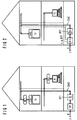
- Figur 1
- ein Hausnetz mit einer Netzabschlußeinrichtung beim Teilnehmer und
- Figur 2
- ein Hausnetz mit einer Netzabschlußeinrichtung am Übergabepunkt.
Der Übergabepunkt ÜP stellt die Grenze zwischen dem öffentlichen Koaxialkabel-Netz und dem Hausnetz dar, er kann gleichzeitig Anschlußstelle für eine Fernspeiseeinrichtung sein, die die im Koaxialkabel-Hausnetz vorhandenen aktiven Einrichtungen, also insbesondere bidirektionale Verstärker und Netzabschlußeinrichtungen mit Strom versorgt. An den Übergabepunkt ÜP schließt sich im Hausnetz ein erster bidirektionaler Verstärker BV1 an, der die von der Zentrale ausgesendeten und am Übergabepunkt ÜP nicht veränderten Signale verstärkt. Vom Ausgang des ersten bidirektionalen Verstärkers BV1 werden die verstärkten Signale über das Koaxialkabel-Hausnetz einer ersten und einer zweiten Netzabschlußeinrichtung NT1, NT2 zugeführt und dort so demoduliert bzw. dekodiert, daß die Signale in einer Set-Top-Box STB1 weiterverarbeitet werden können. Derartige Set-Top-Boxen sind in der "Funkschau", 18/1994, Seiten 72 und 73 beschrieben, diese Set-Top-Boxen enthalten neben Demodulatoren und Decodierern auch einen Rechner und ein angeschlossenes Bedienfeld, durch das beispielsweise Video-Auf-Abruf oder Teleshopping ausgeführt werden kann.
Für den Anschluß eines Personalcomputers PC ist beim Ausführungsbeispiel eine zweite Netzabschlußeinrichtung NT2 vorgesehen, die Set-Top-Box entfällt in diesem Falle, da bereits der Personalcomputer PC über geeignete Signalverarbeitungseinrichtungen verfügt.
Der einfache Aufbau des Hausnetzes nach der Figur 1 führt wegen der kurzen Anschlußlänge zu einer einfachen Anschlußtechnik der Endgeräte, also des Fernsehgerätes und des Personalcomputers, auch ist ein einheitliches Übertragungsverfahren von der Zentrale bis zum Teilnehmer von Vorteil, da keine zusätzlichen Verluste durch ein- oder mehrfachen Wechsel der Modulationsverfahren oder zusätzliche Multiplexer- und Demultiplexer erforderlich sind. Das Koaxialkabel-Hausnetz muß aber bestimmte Anforderungen hinsichtlich der Reflektionsunterdrückung und der Schirmung gegen störende Einstrahlungen erfüllen, auch ergeben sich hohe Ansprüche an den ersten bidirektionalen Verstärker BV1.It shows:
- Figure 1
- a house network with a network termination device at the subscriber and
- Figure 2
- a house network with a network termination device at the transfer point.
The transfer point ÜP represents the boundary between the public coaxial cable network and the house network, it can also be a connection point for a remote feed device that supplies the active devices present in the coaxial cable house network, in particular, bidirectional amplifiers and network termination devices with current. The transfer point ÜP is followed by a first bidirectional amplifier BV1 in the house network, which amplifies the signals transmitted by the control center and not changed at the transfer point ÜP. From the output of the first bidirectional amplifier BV1, the amplified signals are fed via the coaxial cable house network to a first and a second network termination device NT1, NT2 and demodulated or decoded there in such a way that the signals can be processed further in a set-top box STB1. Such set-top boxes are described in the "Funkschau", 18/1994, pages 72 and 73, these set-top boxes contain not only demodulators and decoders, but also a computer and a connected control panel, for example by means of video access or teleshopping can be done.
For the connection of a personal computer PC, a second network termination device NT2 is provided in the exemplary embodiment, the set-top box is omitted in this case, since the personal computer PC already has suitable signal processing devices.
The simple structure of the house network according to FIG. 1 leads to simple connection technology because of the short connection length the end devices, that is, the television set and the personal computer, a uniform transmission method from the center to the subscriber is also advantageous since no additional losses due to one or more changes of the modulation method or additional multiplexer and demultiplexer are required. However, the coaxial cable house network must meet certain requirements with regard to reflection suppression and shielding against interfering radiation, and there are also high demands on the first bidirectional amplifier BV1.
In der Figur 2 ist für das Hausnetz eine einheitliche dritte Netzabschlußeinrichtung NT3 vorgesehen, die am Übergabepunkt ÜP angeordnet ist. Eine derartige Anordnung bietet Vorteile für das an die Zentrale Z angeschlossene Koaxialkabel-Verteilnetz, da dieses definiert abgeschlossen ist und durch Veränderungen und Störungen des Hausnetzes nicht beeinflußt werden kann. Gegenüber der ersten und der zweiten Netzabschlußeinrichtung NT1, NT2 ist in der dritten Netzabschlußeinrichtung NT3 zusätzlich eine Kombination aus einem Demodulator und einem Modulator vorgesehen, durch den die von der Zentrale Z ausgesendeten Signale in solche umgeformt werden, die durch die zweite Set-Top-Box STB2 bzw. den Personalcomputer PC direkt verarbeitet werden können. Die im Hausnetz übertragenen Signale weisen deshalb eine Form auf, wie sie auch für die Übertragung digitaler Video- und/oder Audio-Signale über Satellit bzw. in Kabelverteilnetzen für Fernsehsignale, sogenannten CATV-Netzen, vorgesehen sind. Bei der Übertragung digitaler Signale kann außerdem eine Redundanzverringerung vorgenommen werden, so daß z.B. 6 bis 8 digitale Fernsehsignale in einem 8-MHz-Kanal übertragen werden können. Im Hinblick auf die weitergehende Integration derartiger Geräte ist es auch möglich, die beispielsweise in der zweiten Set-Top-Box STB2 enthaltenen Demodulatoren und Demultiplexer in die Schaltung für den Fernsehempfänger mit zu integrieren. Die vom Teilnehmer ausgehenden Signale betreffen insbesondere Wählsignale für bestimmte Programme bzw. Datensignale vom Personalcomputer PC und Teleshoppingsignale und gegebenenfalls auch ISDN-Signale, alle diese Signale sind vergleichsweise schmalbandig, so daß eine Übertragung dieser Signale im Frequenzband unterhalb des für die Verteilung der Video- und/oder Audiosignale vorgesehenen Frequenzbereichs möglich ist. Wegen der vergleichsweise geringen Dämpfung in diesem Bereich ist eine Verstärkung dieser Signale bis zur dritten Netzabschlußeinrichtung NT3 nicht erforderlich, der zweite bidirektionale Verstärker BV2 verstärkt deshalb nur die von der dritten Netzabschlußeinrichtung NT3 erzeugten Signale und stellt für die Signale der Gegenrichtung nur eine Weiche dar.In Figure 2, a uniform third network termination device NT3 is provided for the house network, which is arranged at the transfer point ÜP. Such an arrangement offers advantages for the coaxial cable distribution network connected to the central station Z, since this is terminated in a defined manner and cannot be influenced by changes and disturbances in the house network. Compared to the first and the second network termination device NT1, NT2, a combination of a demodulator and a modulator is additionally provided in the third network termination device NT3, by means of which the signals transmitted by the control center Z are converted into those which are transmitted through the second set-top box STB2 or the personal computer PC can be processed directly. The signals transmitted in the home network therefore have a form which is also intended for the transmission of digital video and / or audio signals via satellite or in cable distribution networks for television signals, so-called CATV networks. Redundancy can also be reduced when transmitting digital signals, so that, for example, 6 to 8 digital television signals can be transmitted in one 8 MHz channel. With regard to the further integration of such devices, it is also possible to integrate the demodulators and demultiplexers, for example contained in the second set-top box STB2, into the circuit for the television receiver. The signals emanating from the subscriber relate in particular to dial signals for certain programs or data signals from Personal computer PC and teleshopping signals and possibly also ISDN signals, all these signals are comparatively narrow-band, so that these signals can be transmitted in the frequency band below the frequency range provided for the distribution of the video and / or audio signals. Because of the comparatively low attenuation in this area, it is not necessary to amplify these signals up to the third network termination device NT3, the second bidirectional amplifier BV2 therefore only amplifies the signals generated by the third network termination device NT3 and represents only a switch for the signals of the opposite direction.
Eine Alternative zur Übertragung der breitbandigen bidirektionalen Signale ist die in der Figur 2 angedeutete Verwendung von ungeschirmten verdrillten Kupferaderpaaren UTP. Es hat sich gezeigt, daß über derartige ungeschirmte Kupferleitungen über kurze Strecken breitbandige digitale Signale mit einer Bitrate von etwa 50 MBit/s mit ausreichender Störsicherheit übertragen werden können. Damit kann das an sich erforderliche bidirektionalen Koaxialkabel-Hausnetzes bei dieser Variante entfallen, auch ein schmalbandiger Rückweg durch im Hause verlegte Leitungen ist häufig bereits vorhanden.An alternative to the transmission of the broadband bidirectional signals is the use of unshielded twisted copper wire pairs UTP indicated in FIG. 2. It has been shown that broadband digital signals with a bit rate of about 50 Mbit / s can be transmitted with sufficient interference immunity over short distances over such unshielded copper lines. This means that the bidirectional coaxial cable house network that is required per se can be dispensed with in this variant, and there is often also a narrow-band return path through lines laid in-house.
Claims (6)
dadurch gekennzeichnet,
daß zur zusätzlichen bidirektionalen Übertragung teilnehmerbezogener digitaler Signale diese trägerfrequent wenigstens zum überwiegenden Teil in einem Frequenzbereich oberhalb dem der Video- und/oder Audiosignale vom Übergabepunkt zum Teilnehmer übertragen werden,
daß dem Übergabepunkt (ÜP) in Richtung zum Teilnehmer ein bidirektionaler Verstärker (BV) und diesem wenigstens eine Netzabschlußeinrichtung (NT) nachgeschaltet sind und daß einzelne Geräte des Teilnehmers über eine Set-Top-Box (STB) an das Koaxialkabel angeschlossen sind.In-house network for the distribution of video and / or audio signals, in which coaxial cables are routed to the subscriber via a transfer point located in or at the house,
characterized,
that for additional bidirectional transmission of subscriber-related digital signals, these are transmitted at carrier frequency at least for the most part in a frequency range above that of the video and / or audio signals from the transfer point to the subscriber,
that the transfer point (ÜP) towards the subscriber is followed by a bidirectional amplifier (BV) and this at least one network termination device (NT) and that individual devices of the subscriber are connected to the coaxial cable via a set-top box (STB).
dadurch gekennzeichnet,
daß die Netzabschlußeinrichtungen (NT) beim Teilnehmer angeordnet sind und an diese die Set-Top-Boxen (STB) angeschlossen sind.House network according to claim 1,
characterized,
that the network termination devices (NT) are arranged at the subscriber and the set-top boxes (STB) are connected to them.
dadurch gekennzeichnet,
daß die Netzabschlußeinrichtung (NT) am Übergabepunkt (ÜP) angeordnet und dem bidirektionalen Verstärker (BV) vorgeschaltet ist.House network according to claim 1,
characterized,
that the network termination device (NT) is arranged at the transfer point (ÜP) and upstream of the bidirectional amplifier (BV).
dadurch gekennzeichnet,
daß für die Übertragung der teilnehmerbezogenen Signale zwischen den Netzabschlußeinrichtungen (NT) und den Set-Top-Boxen (STB) die gleichen Verfahren verwendet werden, die auch für die Übertragung digitaler Video- und/oder Audiosignale über Satellit bzw. in CATV-Netzen vorgesehen sind.House network according to claim 3,
characterized,
that the same methods are used for the transmission of the subscriber-related signals between the network termination devices (NT) and the set-top boxes (STB) that are also provided for the transmission of digital video and / or audio signals via satellite or in CATV networks are.
dadurch gekennzeichnet,
daß zusätzliche teilnehmerbezogene Schmalbandsignale zwischen den Netzabschlußeinrichtungen (NT) und den Set-Top-Boxen (STB) unterhalb des für die Verteilung der Video- und/oder Audiosignale vorgesehenen Frequenzbereichs übertragen werden.House network according to claim 1,
characterized,
that additional subscriber-related narrowband signals are transmitted between the network termination devices (NT) and the set-top boxes (STB) below the frequency range provided for the distribution of the video and / or audio signals.
dadurch gekennzeichnet,
daß das Koaxialkabel durch ein ungeschirmtes verdrilltes Kupferaderpaar (UTP) wenigstens teilweise ersetzt ist.House network according to claims 1 to 5,
characterized,
that the coaxial cable is at least partially replaced by an unshielded twisted pair of copper wires (UTP).
Applications Claiming Priority (2)
| Application Number | Priority Date | Filing Date | Title |
|---|---|---|---|
| DE4435766 | 1994-10-06 | ||
| DE19944435766 DE4435766A1 (en) | 1994-10-06 | 1994-10-06 | House network for the distribution of video and / or audio signals and for additional bidirectional transmission of subscriber-related signals |
Publications (2)
| Publication Number | Publication Date |
|---|---|
| EP0706293A2 true EP0706293A2 (en) | 1996-04-10 |
| EP0706293A3 EP0706293A3 (en) | 1997-02-05 |
Family
ID=6530126
Family Applications (1)
| Application Number | Title | Priority Date | Filing Date |
|---|---|---|---|
| EP95115476A Withdrawn EP0706293A3 (en) | 1994-10-06 | 1995-09-29 | Domestic network for distributing video and/or audio signals and for additional bidirectional transmission of subscriber related signals |
Country Status (2)
| Country | Link |
|---|---|
| EP (1) | EP0706293A3 (en) |
| DE (1) | DE4435766A1 (en) |
Cited By (1)
| Publication number | Priority date | Publication date | Assignee | Title |
|---|---|---|---|---|
| US6910015B2 (en) * | 2000-03-29 | 2005-06-21 | Sony Corporation | Sales activity management system, sales activity management apparatus, and sales activity management method |
Families Citing this family (1)
| Publication number | Priority date | Publication date | Assignee | Title |
|---|---|---|---|---|
| DE19756163A1 (en) * | 1997-12-17 | 1999-06-24 | Axel Laumer | Television and/or radio program transmission system |
Citations (2)
| Publication number | Priority date | Publication date | Assignee | Title |
|---|---|---|---|---|
| US5283637A (en) * | 1990-08-20 | 1994-02-01 | Christine Holland Trustee/Goolcharan Trust | Telecommunication system for transmitting full motion video |
| WO1994016534A2 (en) * | 1993-01-04 | 1994-07-21 | Com 21, Inc. | A wide area fiber and tv cable fast packet cell network |
-
1994
- 1994-10-06 DE DE19944435766 patent/DE4435766A1/en not_active Withdrawn
-
1995
- 1995-09-29 EP EP95115476A patent/EP0706293A3/en not_active Withdrawn
Patent Citations (2)
| Publication number | Priority date | Publication date | Assignee | Title |
|---|---|---|---|---|
| US5283637A (en) * | 1990-08-20 | 1994-02-01 | Christine Holland Trustee/Goolcharan Trust | Telecommunication system for transmitting full motion video |
| WO1994016534A2 (en) * | 1993-01-04 | 1994-07-21 | Com 21, Inc. | A wide area fiber and tv cable fast packet cell network |
Cited By (1)
| Publication number | Priority date | Publication date | Assignee | Title |
|---|---|---|---|---|
| US6910015B2 (en) * | 2000-03-29 | 2005-06-21 | Sony Corporation | Sales activity management system, sales activity management apparatus, and sales activity management method |
Also Published As
| Publication number | Publication date |
|---|---|
| EP0706293A3 (en) | 1997-02-05 |
| DE4435766A1 (en) | 1996-04-11 |
Similar Documents
| Publication | Publication Date | Title |
|---|---|---|
| DE19702350B4 (en) | Central node converter for connection to a connection of a house network, which is connected with a coaxial cable, and method for communication | |
| DE69916623T2 (en) | AUDIO / VIDEO RE-DISTRIBUTION SYSTEM | |
| DE19848899A1 (en) | Personal computer based set-top converter for television services | |
| DE60215222T2 (en) | HYBRID FIBER OPTIC AND COAXIAL CABLE NETWORK NODES WITH A CABLE MODEM CLOSURE SYSTEM | |
| EP0731619B1 (en) | Broadband communication system and method | |
| DE4436818C1 (en) | Subscriber network | |
| EP0760584B1 (en) | Electrical transmission system with a wide-band distribution system for TV and audio signals and with a possibility for interactive services | |
| EP0706293A2 (en) | Domestic network for distributing video and/or audio signals and for additional bidirectional transmission of subscriber related signals | |
| DE2603644B2 (en) | Community antenna system | |
| DE4342775C2 (en) | Information retrieval system | |
| DE19719425A1 (en) | System for the optical transmission of information | |
| DE19701888A1 (en) | System for the optical transmission of information | |
| EP0710024A2 (en) | Domestic network for connection of subscribers to a public distribution network for video and/or audio signals | |
| DE10344753B4 (en) | Method for bidirectionally transmitting electronic data in a television data cable network | |
| DE19806685A1 (en) | Interactive broadband media | |
| DE19641897C2 (en) | System for the transmission and distribution of television signals with dynamic allocation of the transmission capacity | |
| EP1296487A2 (en) | Method and telecommunication device for transmitting broadcasting information and/or on demand information in a telecommunication network | |
| DE19536682A1 (en) | Transmission system with transfer devices that reduce the effects of interference | |
| DE4435767A1 (en) | Broadband information system for distribution and interactive services | |
| EP0719047A1 (en) | Method for controlling the establischment of connections in interactive services | |
| DE60115838T2 (en) | SYSTEM AND METHOD FOR CONNECTING ENTERTAINMENT DEVICES AND COMPUTERS USING A LOCAL CDMA-BASED NETWORK | |
| DE69819228T2 (en) | Digital television system | |
| DE4433898C2 (en) | Broadband information system for interactive services | |
| EP0059786A2 (en) | Antenna socket | |
| DE19637070B4 (en) | Additional circuit for multimedia communication |
Legal Events
| Date | Code | Title | Description |
|---|---|---|---|
| PUAI | Public reference made under article 153(3) epc to a published international application that has entered the european phase |
Free format text: ORIGINAL CODE: 0009012 |
|
| AK | Designated contracting states |
Kind code of ref document: A2 Designated state(s): AT BE CH DE FR GB IT LI |
|
| PUAL | Search report despatched |
Free format text: ORIGINAL CODE: 0009013 |
|
| AK | Designated contracting states |
Kind code of ref document: A3 Designated state(s): AT BE CH DE FR GB IT LI |
|
| STAA | Information on the status of an ep patent application or granted ep patent |
Free format text: STATUS: THE APPLICATION IS DEEMED TO BE WITHDRAWN |
|
| 18D | Application deemed to be withdrawn |
Effective date: 19970806 |