EP0707842A1 - Motor driven vehicle - Google Patents
Motor driven vehicle Download PDFInfo
- Publication number
- EP0707842A1 EP0707842A1 EP94307591A EP94307591A EP0707842A1 EP 0707842 A1 EP0707842 A1 EP 0707842A1 EP 94307591 A EP94307591 A EP 94307591A EP 94307591 A EP94307591 A EP 94307591A EP 0707842 A1 EP0707842 A1 EP 0707842A1
- Authority
- EP
- European Patent Office
- Prior art keywords
- manual driving
- motor
- force
- wheelchair
- driving
- Prior art date
- Legal status (The legal status is an assumption and is not a legal conclusion. Google has not performed a legal analysis and makes no representation as to the accuracy of the status listed.)
- Withdrawn
Links
Images


Classifications
-
- A—HUMAN NECESSITIES
- A61—MEDICAL OR VETERINARY SCIENCE; HYGIENE
- A61G—TRANSPORT, PERSONAL CONVEYANCES, OR ACCOMMODATION SPECIALLY ADAPTED FOR PATIENTS OR DISABLED PERSONS; OPERATING TABLES OR CHAIRS; CHAIRS FOR DENTISTRY; FUNERAL DEVICES
- A61G5/00—Chairs or personal conveyances specially adapted for patients or disabled persons, e.g. wheelchairs
- A61G5/04—Chairs or personal conveyances specially adapted for patients or disabled persons, e.g. wheelchairs motor-driven
- A61G5/041—Chairs or personal conveyances specially adapted for patients or disabled persons, e.g. wheelchairs motor-driven having a specific drive-type
- A61G5/045—Rear wheel drive
-
- A—HUMAN NECESSITIES
- A61—MEDICAL OR VETERINARY SCIENCE; HYGIENE
- A61G—TRANSPORT, PERSONAL CONVEYANCES, OR ACCOMMODATION SPECIALLY ADAPTED FOR PATIENTS OR DISABLED PERSONS; OPERATING TABLES OR CHAIRS; CHAIRS FOR DENTISTRY; FUNERAL DEVICES
- A61G5/00—Chairs or personal conveyances specially adapted for patients or disabled persons, e.g. wheelchairs
- A61G5/04—Chairs or personal conveyances specially adapted for patients or disabled persons, e.g. wheelchairs motor-driven
- A61G5/048—Power-assistance activated by pushing on hand rim or on handlebar
-
- B—PERFORMING OPERATIONS; TRANSPORTING
- B62—LAND VEHICLES FOR TRAVELLING OTHERWISE THAN ON RAILS
- B62D—MOTOR VEHICLES; TRAILERS
- B62D51/00—Motor vehicles characterised by the driver not being seated
- B62D51/001—Motor vehicles characterised by the driver not being seated characterised by the vehicle control device
-
- B—PERFORMING OPERATIONS; TRANSPORTING
- B62—LAND VEHICLES FOR TRAVELLING OTHERWISE THAN ON RAILS
- B62D—MOTOR VEHICLES; TRAILERS
- B62D51/00—Motor vehicles characterised by the driver not being seated
- B62D51/04—Motor vehicles characterised by the driver not being seated the driver walking
-
- A—HUMAN NECESSITIES
- A61—MEDICAL OR VETERINARY SCIENCE; HYGIENE
- A61G—TRANSPORT, PERSONAL CONVEYANCES, OR ACCOMMODATION SPECIALLY ADAPTED FOR PATIENTS OR DISABLED PERSONS; OPERATING TABLES OR CHAIRS; CHAIRS FOR DENTISTRY; FUNERAL DEVICES
- A61G2203/00—General characteristics of devices
- A61G2203/10—General characteristics of devices characterised by specific control means, e.g. for adjustment or steering
- A61G2203/14—Joysticks
-
- A—HUMAN NECESSITIES
- A61—MEDICAL OR VETERINARY SCIENCE; HYGIENE
- A61G—TRANSPORT, PERSONAL CONVEYANCES, OR ACCOMMODATION SPECIALLY ADAPTED FOR PATIENTS OR DISABLED PERSONS; OPERATING TABLES OR CHAIRS; CHAIRS FOR DENTISTRY; FUNERAL DEVICES
- A61G2203/00—General characteristics of devices
- A61G2203/30—General characteristics of devices characterised by sensor means
- A61G2203/38—General characteristics of devices characterised by sensor means for torque
-
- B—PERFORMING OPERATIONS; TRANSPORTING
- B62—LAND VEHICLES FOR TRAVELLING OTHERWISE THAN ON RAILS
- B62B—HAND-PROPELLED VEHICLES, e.g. HAND CARTS OR PERAMBULATORS; SLEDGES
- B62B5/00—Accessories or details specially adapted for hand carts
- B62B5/0026—Propulsion aids
- B62B5/0069—Control
- B62B5/0073—Measuring a force
Definitions
- This invention relates generally to a motor-driven vehicle, such as a motor-driven wheelchair, and, more particularly, to such a vehicle which can be driven not only by means of an electric motor but also by a helper.
- a motor-driven wheelchair includes a chair-like body on which a user is seated.
- the body is provided with a pair of drive wheels and a pair of followers.
- the drive wheels are coupled to respective motors, and the speed and direction of the rotation of the motors are control led by the user by means of a control lever on a control unit connected to an arm rest of the body. By operating the control lever, the user can move the wheelchair back and forth as he desires.
- the motors are driven from a chargeable battery on the body.
- handgrips are provided, by which a helper can move the wheelchair back and forth.
- An example of such motor-driven wheelchair is described in Unexamined Japanese Utility Model Publication No. SHO 58-97903.
- the motors are coupled via respective gear transmissions with clutches to the drive wheels.
- the helper wants to move the wheelchair by his or her own power, the helper can use the clutches to disengage the drive wheels from the motors so that the helper can move the wheelchair relatively easily.
- the sum of the weight of such a wheelchair and the weight of a user of the wheelchair may sometimes be one-hundred-odd kilograms.
- a helper can move the wheelchair only on a horizontal, flat path.
- the helper may have to use the motors to drive the wheelchair, so that the battery power is consumed much. As a result, the battery needs frequent charging.
- Japanese Unexamined Patent Publication No. HEI 3-15468 discloses another type of wheelchair.
- the wheelchair disclosed in this publication includes a pair of drive wheels mounted to a wheelchair body, and motors for driving the respective drive wheels.
- the motors are also mounted to the body.
- Each of the drive wheels is coupled to a manually driven ring which may be rotated by a user to drive the drive wheel, with torque sensing means for sensing manually applied torque disposed between each of the drive wheels and each of the manually driven ring.
- Each of the torque sensing means includes a torsion bar disposed between the shaft for the associated drive wheel and the shaft for the associated manually driven ring.
- a strain gage is provided on each torsion bar for sensing the torsion thereof caused when the ring is manually driven to rotate.
- the output of the strain gage is applied to a torque sensor to determine the magnitude of the manually applied driving torque exerted to each manually driven ring.
- a control unit controls the respective motors in accordance with the determined driving torques exerted onto the respective manually driven rings.
- a switch is provided for supplying power to the motors. By placing this switch in an OFF position, the motor-driven wheelchair can be driven by man power.
- the torque sensing means requires torsion bars interposed between the shafts for the manually driven rings and the drive wheels, the structure become complicated.
- An object of the present invention is to provide a motor-driven vehicle, such as a motor-driven wheelchair, in which battery power consumed for driving motors is reduced by taking advantage of manual driving-force given by a person, such as a helper, other than a user of the wheelchair.
- manual driving-force means force exerted to a wheelchair by a helper accompanying the wheelchair through a handle (e.g. a handlebar and handgrips) of the wheelchair.
- Another object of the present invention is to provide a motor-driven vehicle with a simplified arrangement for sensing the manual driving-force given to the vehicle.
- a motor-driven vehicle embodying a first aspect to the present invention includes a chair body, a drive wheel mounted on the body, and a motor for driving the wheel to rotate so that the wheelchair can be moved by the motor-power.
- the motor-driven vehicle can be driven also by man power.
- the vehicle is provided with manual driving-force exerting means by which a man can exert a manual driving-force to the vehicle, and manual driving-force sensing means for sensing the manual driving-force exerted to the vehicle and for producing an electrical signal in accordance with the magnitude of the sensed manual driving-force.
- the vehicle further includes control means for controlling the motor in response to the electrical signal.
- the manual driving-force exerting means may be a handle, such as a handlebar and handgrips, provided on the chair body.
- the manual driving-force sensing means may be a load cell mounted on the handle.
- the manual driving-force sensing means may comprise an elastic member forming part of the handle, and strain gages mounted on or embedded in the elastic members.
- Each of the drive wheels includes a fixed shaft extending from the chair body, a center member fixed to the fixed shaft, and a tire which can rotate around the center member.
- the manual driving-force sensing means may be mounted on the fixed shaft.
- a motor-driven wheelchair embodying a second aspect of the present invention includes a chair body, manual driving-force exerting means for exerting manual driving-forces to the wheelchair in the directions along the two opposite sides of the chair body for moving the wheelchair, drive wheels mounted to the chair body on the respective sides of the chair body, and a pair of motors provided for the respective drive wheels for driving the respective drive wheels to rotate.
- the motor-driven wheelchair can be driven by man power.
- a pair of manual driving-force sensing means are provided on the motor-driven wheelchair for sensing the magnitudes of the manual driving-forces, and for producing electrical signals in accordance with the magnitudes of the respective manual driving-forces.
- Control means is provided for receiving the respective electrical signals and for controlling the respective motors which drive the associated ones of said drive wheels on the respective sides of the chair body in accordance with the associated electrical signals.
- a pair of such control means may be provided for the respective ones of the combinations of the motor and the manual driving-force sensing means.
- Each of the control means may be disposed in the drive wheel.
- the manual driving-force exerting means may be a pair of handgrips mounted to the chair body on the opposite sides thereof.
- the manual driving-force sensing means may be a load cell disposed in or on each of the handgrips.
- the manual driving-force sensing means may comprise an elastic member forming part of each handgrip and a strain gage mounted on or embedded in the elastic member.
- Each of the drive wheels includes a fixed shaft extending from the chair body, a center member fixed to the fixed shaft, and a tire which can rotate around the center member.
- the manual driving-force sensing means may be a strain gage mounted on each of the fixed shafts.
- a motor-driven wheelchair according to a first embodiment of the present invention is shown generally by a reference numeral 10.
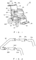
- the wheelchair 10 includes a chair body 12 which is formed of, for example, a pipe frame structure and includes a seat 14, a back 16, foot rests 18, and arm rests 20.
- a pair of right and left drive wheels 22R and 22L are mounted on the chair body 12 in its lower back portions on the opposite sides thereof. (In FIGURE 1, the left drive wheel 22L is not shown. ) In the front lower portions on the right and left sides of the chair body 12, a pair of followers 24R and 24L are mounted to the chair body 12. (The left side follower 24L is not shown in FIGURE 1.)
- the drive wheels 22R and 22L are coupled to respective motors, such as geared DC motors, 26R and 26L (the motor 26L being not shown) via respective gear transmissions (not shown).
- the speed and direction of rotation of the DC motors 26R and 26L are controlled by means of a control lever 30 provided on a control panel 28 mounted to the chair body 12 near one arm rest 20.
- a chargeable battery 32 such as an automobile lead-acid battery, is disposed beneath the seat 14. The DC motors 26R and 26L are driven from the power supplied by the battery 32.
- Handgrips 34R and 34L extend rearward from the upper ends of pipes extending upward along the right and left sides of the back 16. As shown in greater detail in FIGURE 2, couplers 36R and 36L are detachably coupled to the handgrips 34R and 34L.
- Manual driving-force sensing means such as load cells 38R and 38L, are mounted at the ends of the couplers 36R and 36L remote from the handgrips 34R and 34L.
- the load cells 38R and 38L sense pushing and pulling forces manually exerted thereto.
- a U-shaped handlebar 40 may be connected to the load cells 38R and 38L at its respective ends.
- the motor-driven wheelchair can be driven also by man power.
- a helper may push or pull the wheelchair by the handlebar 40.
- a pushing or pulling force applied along each side of the wheelchair 10 is exerted to each of the load cells 38R and 38L, which, in turn, generate analog electrical signals f1R and f1L in accordance with the magnitudes and directions of the manual driving-forces exerted along the right and left sides of the wheelchair 10, respectively.
- the load cells 38R and 38L when a helper pushes the wheelchair forward (i.e. in the positive (+) direction), the load cells 38R and 38L generate electrical signals f1R and f1L, respectively, which are positive and have respective magnitudes proportional to the magnitudes of the forces exerted to the load cells 38R and 38L.
- the load cells 38R and 38L when the wheelchair 10 is pulled backward (i.e. in the negative (-) direction), the load cells 38R and 38L generate signals f1R and f1L which are negative and have respective magnitudes proportional to the magnitudes of the forces exerted thereto.
- the manual driving-forces exerted to the wheelchair 10 can be sensed by a simple structure including the load cells 38R and 38L respectively disposed between the handlebar 40 and the handgrips 34R and 34L.
- analog electrical signals f1R and f1L generated by the load cells 38R and 38L, respectively, are converted into digital signals in an analog-digital (A/D) converter 44 of a signal converting unit 42, which includes, in addition to the A/D converter 44, a CPU 46 and an amplifier 48.
- the digital signals are then applied to the CPU 46 for arithmetic operation.
- the CPU 46 generates digital motor-torque related signals f2R and f2L in accordance with the results of the arithmetic operation carried out in the CPU 46.
- the digital motor-torque related signals f2R and f2L are amplified by the amplifier 48 and, then, applied to control units 50R and 50L which control the motors 26R and 26L, respectively.
- the signal converting unit 42 and the control units 50R and 50L may be placed, for example, within a box 52 disposed on the lead-acid battery 32 (FIGURE 1). Alternatively, only the signal converting unit 42 may be placed in the box 52, while the control units 50R and 50L may be mounted near the drive wheels 22R and 22L, respectively. Since it is not relevant to the subject of the present invention where the signal converting unit 42 and the control units 50R and 50L are placed, not further description about it is necessary.
- the A/D converter 44 alternately selects the analog signals f1R and f1L from the load cells 38R and 38L in response to a control signal applied thereto from the CPU 46, and converts the selected analog signal into a digital signal which is applied to the CPU 46.
- the amplifier 48 is responsive to a control signal applied thereto from the CPU 46 for applying, in an alternating manner, the amplified digital motor-torque related signals f2R and f2L to the control units 50R and 50L, respectively.
- Each control unit 50R (50L) modulates the pulse width of the voltage applied to its associated DC motor 26R (26L) for varying the value of the current supplied to the motor 26R (26L), which results in change of the torque of the motor 26R (26L).
- the speed and direction of rotation of the motor 26R (26L) can be changed.
- the acceleration to drive forward the wheelchair 10 is related to the values of the positive digital motor-torque related signals f2R and f2L, and when the digital motor-torque related signals f2R and f2L are negative, the acceleration to drive backward the wheelchair 10 is related to the values of the negative digital motor-torque related signals f2R and f2L.
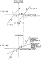
- FIGURE 4a The relationship between the digital motor-torque related signal f2R and the analog electrical signal f1R is shown in FIGURE 4a.
- FIGURE 4b The relationship between the analog electrical signal f1R and the acceleration of the wheelchair 10 is shown in FIGURE 4b.
- a region in which the analog electrical signal f1R has a value between a and b is a dead zone, in which the motor-torque related signal f2R remains 0.
- the digital motor-torque related signal f2R is expressed as K ⁇ f1R - ⁇ and is proportional to the analog electrical signal f1R.
- the digital motor-torque related signal f2R is proportional to the analog electrical signal f1R, but it is expressed as K ⁇ f1R + ⁇ .
- K is a coefficient, and ⁇ and ⁇ are constants.
- the motor-torque related signal f2R is also 0 and, therefore, as shown in FIGURE 4b, the acceleration is also 0.
- the analog electrical signal f1R is at a point B within the dead zone, the motor-torque related signal remains 0, but the acceleration increases by an amount corresponding to the force applied by the helper.
- acceleration is given by the motor 26R, so that the sum of the acceleration due to the motor 26R and the acceleration due to the force given by the helper is applied to the wheelchair.
- the points A and B are exemplified for explanation of acceleration of the wheelchair 10.
- Exemplified points D and E are for explanation of deceleration of the wheelchair 10.
- the motor-torque related signal f2R and the acceleration both exhibit a point-symmetry with the point C being the point of symmetry.
- the acceleration of the motor-driven wheelchair 10 is the sum of the acceleration given by the force applied by the helper and the acceleration given by the motor 26R so that the torque of the motor 26R varies with the magnitude of the force the helper exerts to the load cell 38R.
- the analog electrical signal f1L and the motor-torque related signal f2L are related to each in a similar manner.
- the acceleration of the motor 26R is controlled in accordance with the manual driving-force as sensed by the load cell 38R
- the acceleration of the motor 26L is controlled in accordance with the manual driving-force as sensed by the load cell 38L.
- FIGURES 4a and 4b show the respective relationships when the wheelchair 10 is on a horizontal flat road.
- the accelerations of the respective motors 26R and 26L vary depending on the magnitude of the manual driving-force the helper gives against the gravitational acceleration.
- the dead zone is provided for preventing the motors 26R and 26L from responding to a small manual driving-force to thereby prevent unstable motion of the wheelchair 10.
- the coefficient K, the constants ⁇ and ⁇ , and the values a and b defining the dead zone can be determined to provide a desired acceleration corresponding to a manual driving-force.
- the wheelchair 10 can be driven as if it were driven only by man power. This is explained with reference to FIGURES 5(a) and 5(b).
- FIGURE 5(a) shows variations with time in velocity of the wheelchair 10
- FIGURE 5(b) shows the manual driving-force exerted to the load cells 38R and 38L which cause the variations in velocity of the wheelchair 10 shown in FIGURE 5(a), assuming the the manual driving-forces exerted to the load cells are equal to each other.
- the manual driving-force is positive (+) (i.e. it acts in the direction to move forward the wheelchair 10) and its absolute value is large as in a region A in FIGURE 5(b), the advancing velocity increases at a high rate as shown in a region A in FIGURE 5(a).
- FIGURES 5(a) and 5(b) represent an ideal condition in which there is no friction loss.
- Cases 1 through 5 in the TABLE the manual driving-forces acting on the load cells 38R and 38L are equal to each other.
- Case 1 corresponds to the region C in FIGURE 5(a)
- Case 2 corresponds to the region B
- Case 3 corresponds to the region A
- Case 4 corresponds to the region D
- Case 5 corresponds to the region E of FIGURE 5(a).
- the magnitude of the manual driving-forces are sufficient to develop the electrical signals f1R and f1L which are outside the dead zone shown in FIGURES 4(a) and 4(b).
- the accelerations of the motors 26R and 26L respectively coupled to the drive wheels 22R and 22L vary in accordance with the manual driving-forces acting on the load cells 38R and 38L, respectively.
- the CPU 46 in the signal converting unit 42 performs arithmetic operations as shown in the flow chart of FIGURE 6.
- the control lever 30 of the control panel 28 is in its neutral position.
- a flag indicating which signal is processed a signal from the right-hand side load cell 38R or a signal from the left-hand side load cell 38L, is set to, for example, RIGHT, which means that the signal from the load cell 38R is to be processed (STEP S2).
- RIGHT which means that the signal from the load cell 38R is to be processed
- a digital signal Df1R which is a digitized version of an analog electrical signal f1R from the load cell 38R is read into the CPU 46 from the A/D converter 44 (STEP S6), and is stored therein as data f1 for use in the succeeding arithmetic operations (STEP S8).
- STEP S4 If it is determined in STEP S4 that the flag is set to LEFT (i.e. the judgment made in STEP S4 is NO), which means that the signal from the load cell 38L is to be processed, a digital signal Df1L which is a digitized version of an analog electrical signal f1L from the load cell 38L is read into the CPU 46 from the A/D converter 44 (STEP S10), and is stored therein as data f1 for use in the succeeding arithmetic operations (STEP S12).
- step S8 or S12 judgment is made as to if the data f1 is equal to or larger than the value b defining the lower limit of the dead zone (FIGURE 4(a)) and equal to or less than the value a defining the upper limit of the dead zone (STEP S14). If the answer is YES, which means that the data f1 is within the dead zone, no acceleration is given to the wheelchair by the motor 26R or 26L.
- STEPS S16 and S18 or STEPS S16 and S20 are successively performed, and thereafter, STEP S4 is performed, in order to process the signal from the other load cell.
- the digital electrical signals Df1R and Df1L are alternately read into the CPU 46, and the motors 26R and 26L are controlled to produce acceleration corresponding to the signals f1R and f1L, respectively.
- a motor-driven wheelchair according to a second embodiment of the present invention is constructed similar to the wheelchair 10 of the first embodiment, except that, as shown in FIGURES 7(a), 7(b) and 7(c), only strain gages 54R and 54L are mounted as the manual driving-force sensing means. Therefore the same references are used for portions equivalent to those of the motor-driven wheelchair 10, and no further explanation of them is made. (The strain gage 54L is not shown in FIGURES 7(a), 7(b) and 7(c).)
- an elastic material such as rubber, is disposed to surround the end of the handgrip 34R to provide an elastic grip 52R.
- a strain gage 54R is mounted in the end surface of the elastic grip 52R.
- an elastic grip 52L (not shown) is provided at the end of the other handgrip 34L, and another strain gage 54L is mounted on or embedded in the end surface of the elastic grip 52L (not shown).
- the manual driving-forces exerted by the helper to the motor-driven wheelchair 10 in the respective directions along the right and left sides of the wheelchair 10 can be sensed by means of the analog electrical signals generated by the respective strain gages 54R and 54L.
- a manual driving-force sensing circuit may comprise a bridge circuit including the strain gages 54R and 54L arranged in such a configuration that when an expanding force is exerted to the strain gage 54R, 54L, a positive (+) analog electrical signal may be generated, whereas a compressing force exerted to the strain gage 54R, 54L may generate a negative (-) analog electrical signal.
- the motors 26R and 25L can be controlled in accordance with the magnitudes of the manual driving-forces exerted to the wheelchair. Because the strain gages 54R and 54L are placed in the handgrips 52R and 52L, respectively, to which the helper exerts the manual driving-forces directly, the exact manual driving-forces can be sensed.
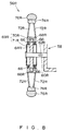
- a motor-driven wheelchair includes a drive wheel arrangement shown in FIGURE 8.
- a strain gage 62R functioning as manual driving-force sensing means is mounted on a fixed shaft 60R coupling a right-hand side drive wheel 56R to a chair body 58.
- a similar strain gage 62L is also mounted on a fixed shaft 60L for the left-hand side drive wheel 56L. Since the drive wheel arrangements for the both drive wheels are the same, only that of the right drive wheel 56R is described.
- the fixed shaft 60R extends outward from the right side of the chair body 58, in the direction substantially perpendicular to the direction of a manual driving-force exerted to the chair body 58 to move it forward or backward.
- a center member 64R having, for example, a disc-shape is connected to the fixed shaft 60R, and a hub 68R is rotatably mounted around the center member 64R with a plurality of bearings 66 disposed between them.
- the hub 68R is coupled to a rotor 70R of an outer-rotor type DC motor 69R.
- the DC motor 69R includes a stator 71R which is fixedly mounted to the center member 64, and the outer rotor 70R is in slidable contact with the stator 71R.
- the hub 68R is coupled to an annular rim 74R through a plurality of radially extending spokes 72R.
- a tire 76R is fitted over the rim 74R.
- the drive wheels 56R and 56L are substantially larger in diameter than the drive wheels 22R and 22L shown in FIGURE 1.
- This drive wheel arrangement is such that the tire 76R is rotated by driving the hub 68R to rotate by means of the outer-rotor DC motor 69R, and, therefore, the center member 64R does not rotate.
- the center member 64R houses therein a converting unit and a control unit equivalent respectively to the converting unit 42 and the control unit 52R shown in FIGURE 3, and batteries (not shown) for driving the converting and control units and the motor 69R.
- the converting unit is placed in one center member, no converting member is need be housed in the other center member.
- the strain gages 62R and 62L are mounted longitudinally along the length of the fixed shafts 60R and 60L.
- a helper pushes or pulls the wheelchair by means of a handlebar or handgrips to thereby exert manual driving-forces to the wheelchair in the directions along the opposite sides thereof
- the manual driving-forces are transmitted via the chair body 58 and the respective fixed shafts 56R to the strain gages 60R and 60L in the directions perpendicular to the plane of the sheet of FIGURE 8 Accordingly, compression or expansion forces corresponding to the exerted manual driving-forces act on the respective strain gages 60R and 60L.
- a manual driving-force sensing circuit including a bridge circuit comprising the strain gage 68R (68L) can be used to generate an analog electrical signal similar to the analog electrical signal f1R (f1L) generated by the load cell 38R (38L) of the first embodiment, which is proportional to the compression or expansion force acting on the strain gage. This analog electrical signals are used to control the respective DC motors.
- the number of required wires is reduced, so that the wheelchair is suitable for mass-product ion with a reduced number of assembling steps.
- only one strain gage (62R or 62L) is shown, but two or more strain gages may be arranged on the shaft 60 along its length. Further, in addition to the strain gage(s) 62R (62L), another strain gage(s) may be disposed on the opposite sides of the fixed shaft 60R (60L).
- strain gages 62R and 62L are mounted directly on the fixed shafts 60R and 60L, respectively, no torsion bars are required, which simplifies the structure.
- the drive wheels comprise a pair of rear wheels.
- the rear wheels may be followers with one drive wheel disposed between the two rear wheels, which drive wheel is driven in accordance with the magnitude of the manual driving force exerted to the motor-driving wheelchair.
Abstract
A motor-driven wheelchair includes a chair body, a pair of drive wheels mounted on the chair body, and a pair of motors for driving said drive wheels to rotate. By operating the motors, the wheelchair can be moved. The wheelchair further includes a pair of manual driving-force sensing means, which senses manual driving-forces exerted by a man to the motor-driven wheelchair along each side of the chair body to move the wheelchair by man power. The sensing means generates electrical signals corresponding to the respective manual driving-forces. Control means is provided to individually control the velocities of the respective motors in accordance with the respective electrical signals.
Description
- This invention relates generally to a motor-driven vehicle, such as a motor-driven wheelchair, and, more particularly, to such a vehicle which can be driven not only by means of an electric motor but also by a helper.
- A motor-driven wheelchair includes a chair-like body on which a user is seated. The body is provided with a pair of drive wheels and a pair of followers. The drive wheels are coupled to respective motors, and the speed and direction of the rotation of the motors are control led by the user by means of a control lever on a control unit connected to an arm rest of the body. By operating the control lever, the user can move the wheelchair back and forth as he desires. The motors are driven from a chargeable battery on the body. In the rear portion of the wheelchair, handgrips are provided, by which a helper can move the wheelchair back and forth. An example of such motor-driven wheelchair is described in Unexamined Japanese Utility Model Publication No. SHO 58-97903.
- Usually, the motors are coupled via respective gear transmissions with clutches to the drive wheels. When the helper wants to move the wheelchair by his or her own power, the helper can use the clutches to disengage the drive wheels from the motors so that the helper can move the wheelchair relatively easily.
- The sum of the weight of such a wheelchair and the weight of a user of the wheelchair may sometimes be one-hundred-odd kilograms. In such a case, a helper can move the wheelchair only on a horizontal, flat path. In some cases, for example, when the helper must push the wheelchair with the user seated thereon up a slope, the helper may have to use the motors to drive the wheelchair, so that the battery power is consumed much. As a result, the battery needs frequent charging.
- Japanese Unexamined Patent Publication No. HEI 3-15468 discloses another type of wheelchair. The wheelchair disclosed in this publication includes a pair of drive wheels mounted to a wheelchair body, and motors for driving the respective drive wheels. The motors are also mounted to the body. Each of the drive wheels is coupled to a manually driven ring which may be rotated by a user to drive the drive wheel, with torque sensing means for sensing manually applied torque disposed between each of the drive wheels and each of the manually driven ring. Each of the torque sensing means includes a torsion bar disposed between the shaft for the associated drive wheel and the shaft for the associated manually driven ring. A strain gage is provided on each torsion bar for sensing the torsion thereof caused when the ring is manually driven to rotate. The output of the strain gage is applied to a torque sensor to determine the magnitude of the manually applied driving torque exerted to each manually driven ring. A control unit controls the respective motors in accordance with the determined driving torques exerted onto the respective manually driven rings. A switch is provided for supplying power to the motors. By placing this switch in an OFF position, the motor-driven wheelchair can be driven by man power.
- In order to move the wheelchair of this publication by means of the motors, a user must manually impart driving torques to the manually driven rings. If no torque is given, the motors will not operate. Therefore, if the user cannot use his or her hands to manually drive the rings, the wheelchair cannot move. Sometimes, for such a user, a helper may accompany him or her, but, unless the helper drives the manually driven rings, he cannot take advantage of the motor power. Then, he must switch off the power supply for the motors. Even in such a case, however, more power must be used than required for driving an ordinary man-power wheelchair, because of the added weight of the motors mounted on the wheelchair.
- In addition, according to the disclosure of this publication, the torque sensing means requires torsion bars interposed between the shafts for the manually driven rings and the drive wheels, the structure become complicated.
- An object of the present invention is to provide a motor-driven vehicle, such as a motor-driven wheelchair, in which battery power consumed for driving motors is reduced by taking advantage of manual driving-force given by a person, such as a helper, other than a user of the wheelchair. In this specification, the term "manual driving-force" means force exerted to a wheelchair by a helper accompanying the wheelchair through a handle (e.g. a handlebar and handgrips) of the wheelchair.
- Another object of the present invention is to provide a motor-driven vehicle with a simplified arrangement for sensing the manual driving-force given to the vehicle.
- Other objects and features of the present invention will become clear from the following description of the invention.
- A motor-driven vehicle embodying a first aspect to the present invention includes a chair body, a drive wheel mounted on the body, and a motor for driving the wheel to rotate so that the wheelchair can be moved by the motor-power. The motor-driven vehicle can be driven also by man power. The vehicle is provided with manual driving-force exerting means by which a man can exert a manual driving-force to the vehicle, and manual driving-force sensing means for sensing the manual driving-force exerted to the vehicle and for producing an electrical signal in accordance with the magnitude of the sensed manual driving-force. The vehicle further includes control means for controlling the motor in response to the electrical signal.
- The manual driving-force exerting means may be a handle, such as a handlebar and handgrips, provided on the chair body. The manual driving-force sensing means may be a load cell mounted on the handle. The manual driving-force sensing means may comprise an elastic member forming part of the handle, and strain gages mounted on or embedded in the elastic members.
- Each of the drive wheels includes a fixed shaft extending from the chair body, a center member fixed to the fixed shaft, and a tire which can rotate around the center member. The manual driving-force sensing means may be mounted on the fixed shaft.
- A motor-driven wheelchair embodying a second aspect of the present invention includes a chair body, manual driving-force exerting means for exerting manual driving-forces to the wheelchair in the directions along the two opposite sides of the chair body for moving the wheelchair, drive wheels mounted to the chair body on the respective sides of the chair body, and a pair of motors provided for the respective drive wheels for driving the respective drive wheels to rotate.
- The motor-driven wheelchair can be driven by man power. A pair of manual driving-force sensing means are provided on the motor-driven wheelchair for sensing the magnitudes of the manual driving-forces, and for producing electrical signals in accordance with the magnitudes of the respective manual driving-forces. Control means is provided for receiving the respective electrical signals and for controlling the respective motors which drive the associated ones of said drive wheels on the respective sides of the chair body in accordance with the associated electrical signals.
- A pair of such control means may be provided for the respective ones of the combinations of the motor and the manual driving-force sensing means. Each of the control means may be disposed in the drive wheel.
- The manual driving-force exerting means may be a pair of handgrips mounted to the chair body on the opposite sides thereof. The manual driving-force sensing means may be a load cell disposed in or on each of the handgrips. Alternatively, the manual driving-force sensing means may comprise an elastic member forming part of each handgrip and a strain gage mounted on or embedded in the elastic member.
- Each of the drive wheels includes a fixed shaft extending from the chair body, a center member fixed to the fixed shaft, and a tire which can rotate around the center member. The manual driving-force sensing means may be a strain gage mounted on each of the fixed shafts.
-
- FIGURE 1 is a perspective view of a motor-driven wheelchair embodying the present invention;
- FIGURE 2 is an exploded view of a part of the the wheelchair shown in FIGURE 1;
- FIGURE 3 is a block diagram of a control section of the wheelchair shown in FIGURE 1;
- FIGURE 4a shows a relationship between an electrical signal from one of load cells and an associated motor-torque related signal in the wheelchair shown in FIGURE 1;
- FIGURE 4b shows a relationship between the electrical signal shown in FIGURE 4a and an acceleration of the wheelchair shown in FIGURE 1;
- FIGURES 5a and 5b show a relationship between the velocity of the wheelchair shown in FIGURE 1 and the manual driving-force exerted to the wheelchair, in which FIGURE 5a shows an example of change in velocity with time, and FIGURE 5b shows the manual driving-force exerted to the wheelchair;
- FIGURE 6 is a flow chart showing the arithmetic processing by a CPU in a signal converting unit of the wheelchair shown in FIGURE 1;
- FIGURE 7a shows a longitudinal cross-section of a handgrip of another example of a motor-driven wheelchair embodying the present invention, FIGURE 7b shows a corresponding cross-section of the handgrip of FIGURE 7a with a force manually exerted to it in a direction indicated by an arrow A, and FIGURE 7c shows a corresponding cross-section of the handgrip of FIGURE 7a with force manually exerted to it in a direction indicated by an arrow B;
- FIGURE 8 is a cross-sectional view of one of drive wheels of a motor-driven wheelchair according to another embodiment of the present invention; and
- In FIGURE 1, a motor-driven wheelchair according to a first embodiment of the present invention is shown generally by a
reference numeral 10. As shown in FIGURE 1, thewheelchair 10 includes achair body 12 which is formed of, for example, a pipe frame structure and includes aseat 14, a back 16, foot rests 18, and arm rests 20. - A pair of right and left
drive wheels 22R and 22L are mounted on thechair body 12 in its lower back portions on the opposite sides thereof. (In FIGURE 1, the left drive wheel 22L is not shown. ) In the front lower portions on the right and left sides of thechair body 12, a pair of followers 24R and 24L are mounted to thechair body 12. (The left side follower 24L is not shown in FIGURE 1.) Thedrive wheels 22R and 22L are coupled to respective motors, such as geared DC motors, 26R and 26L (themotor 26L being not shown) via respective gear transmissions (not shown). The speed and direction of rotation of theDC motors control lever 30 provided on acontrol panel 28 mounted to thechair body 12 near onearm rest 20. Achargeable battery 32, such as an automobile lead-acid battery, is disposed beneath theseat 14. TheDC motors battery 32. -
Handgrips couplers handgrips load cells couplers handgrips load cells U-shaped handlebar 40 may be connected to theload cells - The motor-driven wheelchair can be driven also by man power. A helper may push or pull the wheelchair by the
handlebar 40. A pushing or pulling force applied along each side of thewheelchair 10 is exerted to each of theload cells wheelchair 10, respectively. For example, when a helper pushes the wheelchair forward (i.e. in the positive (+) direction), theload cells load cells wheelchair 10 is pulled backward (i.e. in the negative (-) direction), theload cells - When the helper exerts such forces to the
handlebar 40 as to turn right or left thewheelchair 10 or to rotate counterclockwise or clockwise, a component of the manual driving-force acting on thewheelchair 10 and tending to move it forward, or a component of the force tending to move thewheelchair 10 backward is exerted to a respective one of theload cells 38 and 38L so that electrical signals f1R and f1L corresponding to the respective components are generated. - Thus, the manual driving-forces exerted to the
wheelchair 10 can be sensed by a simple structure including theload cells handlebar 40 and thehandgrips - As shown in FIGURE 3, analog electrical signals f1R and f1L generated by the
load cells converter 44 of asignal converting unit 42, which includes, in addition to the A/D converter 44, aCPU 46 and anamplifier 48. The digital signals are then applied to theCPU 46 for arithmetic operation. TheCPU 46 generates digital motor-torque related signals f2R and f2L in accordance with the results of the arithmetic operation carried out in theCPU 46. The digital motor-torque related signals f2R and f2L are amplified by theamplifier 48 and, then, applied to controlunits motors - The
signal converting unit 42 and thecontrol units box 52 disposed on the lead-acid battery 32 (FIGURE 1). Alternatively, only thesignal converting unit 42 may be placed in thebox 52, while thecontrol units drive wheels 22R and 22L, respectively. Since it is not relevant to the subject of the present invention where thesignal converting unit 42 and thecontrol units - The A/
D converter 44 alternately selects the analog signals f1R and f1L from theload cells CPU 46, and converts the selected analog signal into a digital signal which is applied to theCPU 46. - The
amplifier 48 is responsive to a control signal applied thereto from theCPU 46 for applying, in an alternating manner, the amplified digital motor-torque related signals f2R and f2L to thecontrol units - Each
control unit 50R (50L) modulates the pulse width of the voltage applied to its associatedDC motor 26R (26L) for varying the value of the current supplied to themotor 26R (26L), which results in change of the torque of themotor 26R (26L). Thus, the speed and direction of rotation of themotor 26R (26L) can be changed. - When the digital motor-torque related signals f2R and f2L are positive, the acceleration to drive forward the
wheelchair 10 is related to the values of the positive digital motor-torque related signals f2R and f2L, and when the digital motor-torque related signals f2R and f2L are negative, the acceleration to drive backward thewheelchair 10 is related to the values of the negative digital motor-torque related signals f2R and f2L. - The relationship between the digital motor-torque related signal f2R and the analog electrical signal f1R is shown in FIGURE 4a. The relationship between the analog electrical signal f1R and the acceleration of the
wheelchair 10 is shown in FIGURE 4b. As is seen from FIGURE 4a, a region in which the analog electrical signal f1R has a value between a and b is a dead zone, in which the motor-torque related signal f2R remains 0. With the analog electrical signal f1R being greater than a, the digital motor-torque related signal

- For example, when the value of the analog electrical signal f1R is at a point C in FIGURE 4a, which means that the manual driving-force exerted to the
load cell 38R is 0, the motor-torque related signal f2R is also 0 and, therefore, as shown in FIGURE 4b, the acceleration is also 0. When the analog electrical signal f1R is at a point B within the dead zone, the motor-torque related signal remains 0, but the acceleration increases by an amount corresponding to the force applied by the helper. At a point A where the analog electrical signal f1R is greater than a, acceleration is given by themotor 26R, so that the sum of the acceleration due to themotor 26R and the acceleration due to the force given by the helper is applied to the wheelchair. The points A and B are exemplified for explanation of acceleration of thewheelchair 10. Exemplified points D and E are for explanation of deceleration of thewheelchair 10. The motor-torque related signal f2R and the acceleration both exhibit a point-symmetry with the point C being the point of symmetry. - Specifically, at the point A or E, the acceleration of the motor-driven
wheelchair 10 is the sum of the acceleration given by the force applied by the helper and the acceleration given by themotor 26R so that the torque of themotor 26R varies with the magnitude of the force the helper exerts to theload cell 38R. - The analog electrical signal f1L and the motor-torque related signal f2L are related to each in a similar manner. Thus, the acceleration of the
motor 26R is controlled in accordance with the manual driving-force as sensed by theload cell 38R, and the acceleration of themotor 26L is controlled in accordance with the manual driving-force as sensed by theload cell 38L. - FIGURES 4a and 4b show the respective relationships when the
wheelchair 10 is on a horizontal flat road. When the wheelchair is driven up and down a slope, the accelerations of therespective motors - The dead zone is provided for preventing the
motors wheelchair 10. The coefficient K, the constants α and β, and the values a and b defining the dead zone can be determined to provide a desired acceleration corresponding to a manual driving-force. - Since it is not that the
motors wheelchair 10 can be driven as if it were driven only by man power. This is explained with reference to FIGURES 5(a) and 5(b). - FIGURE 5(a) shows variations with time in velocity of the
wheelchair 10, and FIGURE 5(b) shows the manual driving-force exerted to theload cells wheelchair 10 shown in FIGURE 5(a), assuming the the manual driving-forces exerted to the load cells are equal to each other. When the manual driving-force is positive (+) (i.e. it acts in the direction to move forward the wheelchair 10) and its absolute value is large as in a region A in FIGURE 5(b), the advancing velocity increases at a high rate as shown in a region A in FIGURE 5(a). When the manual driving-force is positive and its absolute value is small as in a region B (FIGURE 5(b)), the rate of increase of the wheelchair advancing velocity is gradual as shown in FIGURE 5(a). When the manual driving-force applied is zero as in a region C in FIGURE 5(b), the velocity of thewheelchair 10 does not change and the wheelchair moves forward by inertia as shown in FIGURE 5(a) in a region C. - When the manual driving-force is negative (-) (i.e. it acts in the direction to move the
wheelchair 10 backward) and its absolute value is small as in a region D in FIGURE 5(b), the advancing velocity of thewheelchair 10 decreases gradually, as in a region D in FIGURE 5(a). If the manual driving-force is negative and its absolute value is large as in a region E, the velocity decreases rapidly. It should be noted that FIGURES 5(a) and 5(b) represent an ideal condition in which there is no friction loss. - In the above description, simple acceleration and deceleration of the
wheelchair 10 are described. It should be note that since themotors respective load cells wheelchair 10 can change its direction. The direction changing operation of thewheelchair 10 is now described with reference to the following TABLE.TABLE Case Manual Driving Forces Movement of Wheelchair Left Right 1 0 0 Steady Movement 2 (+) Small (+) Small Small Acceleration 3 (+) Large (+) Large Large Acceleration 4 (-) Small (-) Small Small Deceleration 5 (-) Large (-) Large Large Deceleration 6 (+) Small (+) Large Turning Left 7 (-) Small (+) Large Rapidly Turning Left 8 (-) Large (+) Large Rotating Counterclockwise 9 (+) Large (+) Small Turning Right 10 (+) Large (-) Small Rapidly Turning Right 11 (+) Large (-) Large Rotating Clockwise - In Cases 1 through 5 in the TABLE, the manual driving-forces acting on the
load cells - In each of
Cases 6 through 11, the manual driving-forces acting on therespective load cells motors wheelchair 10 change its direction of movement. - In
Case 6, the manual driving-force acting on theload cell 38L is in the positive direction and the absolute value of the magnitude is small, while the manual driving-force acting on theload cell 38L is also in the positive direction, but the absolute value of the magnitude is larger. In this case, the acceleration provided by themotor 26L and the acceleration provided by the manual driving-force the helper exerts to thewheelchair 10 are summed. However, since the manual driving-force is not large, the acceleration given to the drive wheel 22L is not large. With the manual driving-force acting on theload cell 38R being positive and large in absolute value, the sum of the acceleration due to the manual driving-force given by the helper and the acceleration due to themotor 26R is given to thedrive wheel 22R. Thus, the acceleration occurring to the drive wheel 22L and the acceleration occurring to thedrive wheel 22R are in the same direction, but the magnitude of the acceleration of the drive wheel 22L is smaller. Accordingly, thewheelchair 10 turns left. - In Case 7, the manual driving-force applied to the
load cell 36L is negative and its absolute value is small, while the manual driving-force applied to theload cell 36R is positive and its absolute value is large. In this case, the acceleration of thedrive wheel 22R is similar to that in Case 5. However, the acceleration of the drive wheel 22L is in the opposite direction to that in Case 5. Accordingly, thewheelchair 10 turns left rapidly. - In Case 8 where the manual driving-force acting on the
load cell 38L is negative and large in negative value, while the manual driving-force acting on theload cell 38R is positive and large in absolute value, the acceleration of thedrive wheel 22R is similar to that inCase 6 and the acceleration of the wheel 22L is in the opposite direction to that inCase 6 and large. Accordingly, thewheelchair 10 rotates counterclockwise. - In Case 9, the manual driving-force acting on the
load cell 38L is positive and large in absolute value, whereas the manual driving-force acting on theload cell 38R is negative and small in absolute value. This situation is opposite to Case 5, and, therefore, thewheelchair 10 turns right. - When the manual driving-force acting on the
load cell 38L is positive and large in absolute value, while the manual driving-force acting on theload cell 38R is negative and small in absolute value, as inCase 10, thewheelchair 10 turns right rapidly, which is opposite to Case 7. - In Case 11, the manual driving-force acting on the
load cell 38L is positive and its absolute value is large, whereas the manual driving-force acting on theload cell 38R is negative and large in absolute value. This is a case opposite to Case 8, so that the wheelchair rotates clockwise. - As described above, the accelerations of the
motors drive wheels 22R and 22L vary in accordance with the manual driving-forces acting on theload cells - In order to control the acceleration and direction of motion of the
wheelchair 10 as described, theCPU 46 in thesignal converting unit 42 performs arithmetic operations as shown in the flow chart of FIGURE 6. When the arithmetic operations are carried out, thecontrol lever 30 of thecontrol panel 28 is in its neutral position. - Immediately after the start of the arithmetic operation, a flag indicating which signal is processed, a signal from the right-hand
side load cell 38R or a signal from the left-handside load cell 38L, is set to, for example, RIGHT, which means that the signal from theload cell 38R is to be processed (STEP S2). Next, whether the flag is set to RIGHT or LEFT is determined (STEP S4). If the flag is set to RIGHT (i.e. the judgment made by STEP S4 is YES), a digital signal Df1R which is a digitized version of an analog electrical signal f1R from theload cell 38R is read into theCPU 46 from the A/D converter 44 (STEP S6), and is stored therein as data f1 for use in the succeeding arithmetic operations (STEP S8). - If it is determined in STEP S4 that the flag is set to LEFT (i.e. the judgment made in STEP S4 is NO), which means that the signal from the
load cell 38L is to be processed, a digital signal Df1L which is a digitized version of an analog electrical signal f1L from theload cell 38L is read into theCPU 46 from the A/D converter 44 (STEP S10), and is stored therein as data f1 for use in the succeeding arithmetic operations (STEP S12). - After the step S8 or S12, judgment is made as to if the data f1 is equal to or larger than the value b defining the lower limit of the dead zone (FIGURE 4(a)) and equal to or less than the value a defining the upper limit of the dead zone (STEP S14). If the answer is YES, which means that the data f1 is within the dead zone, no acceleration is given to the wheelchair by the
motor - Next, in order to process a signal from the other load cell, judgment is made as to whether the flag is set RIGHT or not (STEP S16). If the answer is YES, the flag is set to LEFT in order to next process the signal from the left-hand
side load cell 38L (STEP S18), and the processing returns to STEP S4. - If the judgment in STEP S14 is NO, which means that the data f1 is outside the dead zone, acceleration is to be given to the wheelchair by the
motor 
amplifier 48 is controlled so that the result of the arithmetic operation, i.e. data f2, is developed as the motor-torque related signal f2R (STEP S26). - On the other hand, if the data f1 is judged to be less than 0 in STEP S22, an arithmetic operation

amplifier 48 is controlled so that the result of the arithmetic operation, i.e. data f2, is outputted as the motor-torque related signal f2L (STEP S30). - Following STEP S26 or S30, STEPS S16 and S18 or STEPS S16 and S20 are successively performed, and thereafter, STEP S4 is performed, in order to process the signal from the other load cell.
- In the manner as stated above, the digital electrical signals Df1R and Df1L are alternately read into the
CPU 46, and themotors - A motor-driven wheelchair according to a second embodiment of the present invention is constructed similar to the
wheelchair 10 of the first embodiment, except that, as shown in FIGURES 7(a), 7(b) and 7(c), onlystrain gages 54R and 54L are mounted as the manual driving-force sensing means. Therefore the same references are used for portions equivalent to those of the motor-drivenwheelchair 10, and no further explanation of them is made. (The strain gage 54L is not shown in FIGURES 7(a), 7(b) and 7(c).) - As shown, at the end of one
handgrip 34R, an elastic material, such as rubber, is disposed to surround the end of thehandgrip 34R to provide anelastic grip 52R. Astrain gage 54R is mounted in the end surface of theelastic grip 52R. Similarly, an elastic grip 52L (not shown) is provided at the end of theother handgrip 34L, and another strain gage 54L is mounted on or embedded in the end surface of the elastic grip 52L (not shown). - As shown in FIGURE 7(a), when no manual driving-force is acting on the
grip 52R or 52L, it is not deformed at all. - When forces are applied to the wheelchair by the
grips 52R and 52L to move the wheelchair forward, thegrips 52R and 52L are deformed in the direction indicated by an arrow A in FIGURE 7(b) so that expanding force is exerted onto each of thestrain gages 54R and 54L. - On the other hand, if the manual driving-forces to move the wheelchair backward are applied to the the
elastic grips 52R and 52L, thegrips 52R and 52L are deformed in the direction as indicated by an arrow B in FIGURE 7(c), and compressing force is exerted onto each of thestrain gages 54R and 54L. - As described above, the manual driving-forces exerted by the helper to the motor-driven
wheelchair 10 in the respective directions along the right and left sides of thewheelchair 10 can be sensed by means of the analog electrical signals generated by therespective strain gages 54R and 54L. - A manual driving-force sensing circuit may comprise a bridge circuit including the
strain gages 54R and 54L arranged in such a configuration that when an expanding force is exerted to thestrain gage 54R, 54L, a positive (+) analog electrical signal may be generated, whereas a compressing force exerted to thestrain gage 54R, 54L may generate a negative (-) analog electrical signal. With this manual driving-force sensing circuit, themotors 26R and 25L can be controlled in accordance with the magnitudes of the manual driving-forces exerted to the wheelchair. Because thestrain gages 54R and 54L are placed in thehandgrips 52R and 52L, respectively, to which the helper exerts the manual driving-forces directly, the exact manual driving-forces can be sensed. - A motor-driven wheelchair according to a third embodiment of the present invention includes a drive wheel arrangement shown in FIGURE 8. A
strain gage 62R functioning as manual driving-force sensing means is mounted on a fixedshaft 60R coupling a right-handside drive wheel 56R to achair body 58.
A similar strain gage 62L is also mounted on a fixed shaft 60L for the left-hand side drive wheel 56L. Since the drive wheel arrangements for the both drive wheels are the same, only that of theright drive wheel 56R is described. - The fixed
shaft 60R extends outward from the right side of thechair body 58, in the direction substantially perpendicular to the direction of a manual driving-force exerted to thechair body 58 to move it forward or backward. Acenter member 64R having, for example, a disc-shape is connected to the fixedshaft 60R, and ahub 68R is rotatably mounted around thecenter member 64R with a plurality ofbearings 66 disposed between them. Thehub 68R is coupled to arotor 70R of an outer-rotortype DC motor 69R. TheDC motor 69R includes a stator 71R which is fixedly mounted to the center member 64, and theouter rotor 70R is in slidable contact with the stator 71R. The arrangement of an outer-rotor of this type is disclosed in greater detail in, for example, Japanese Unexamined Utility Model Publication No. HEI 1-172826, and, therefore, for further details of the arrangement of theDC motor 69R, reference should be made to this publication. - The
hub 68R is coupled to anannular rim 74R through a plurality of radially extendingspokes 72R. Atire 76R is fitted over therim 74R. Thedrive wheels 56R and 56L are substantially larger in diameter than thedrive wheels 22R and 22L shown in FIGURE 1. - This drive wheel arrangement is such that the
tire 76R is rotated by driving thehub 68R to rotate by means of the outer-rotor DC motor 69R, and, therefore, thecenter member 64R does not rotate. Thecenter member 64R houses therein a converting unit and a control unit equivalent respectively to the convertingunit 42 and thecontrol unit 52R shown in FIGURE 3, and batteries (not shown) for driving the converting and control units and themotor 69R. When the converting unit is placed in one center member, no converting member is need be housed in the other center member. - The
strain gages 62R and 62L are mounted longitudinally along the length of the fixedshafts 60R and 60L. When a helper pushes or pulls the wheelchair by means of a handlebar or handgrips to thereby exert manual driving-forces to the wheelchair in the directions along the opposite sides thereof, the manual driving-forces are transmitted via thechair body 58 and the respective fixedshafts 56R to thestrain gages 60R and 60L in the directions perpendicular to the plane of the sheet of FIGURE 8 Accordingly, compression or expansion forces corresponding to the exerted manual driving-forces act on therespective strain gages 60R and 60L. A manual driving-force sensing circuit including a bridge circuit comprising thestrain gage 68R (68L) can be used to generate an analog electrical signal similar to the analog electrical signal f1R (f1L) generated by theload cell 38R (38L) of the first embodiment, which is proportional to the compression or expansion force acting on the strain gage. This analog electrical signals are used to control the respective DC motors. - With the battery and the control unit etc. housed in each of the center members as stated above, the number of required wires is reduced, so that the wheelchair is suitable for mass-product ion with a reduced number of assembling steps. In the embodiment shown in FIGURE 8, only one strain gage (62R or 62L) is shown, but two or more strain gages may be arranged on the shaft 60 along its length. Further, in addition to the strain gage(s) 62R (62L), another strain gage(s) may be disposed on the opposite sides of the fixed
shaft 60R (60L). - According to this embodiment, since the
strain gages 62R and 62L are mounted directly on the fixedshafts 60R and 60L, respectively, no torsion bars are required, which simplifies the structure. - In the described embodiments, the drive wheels comprise a pair of rear wheels. However, the rear wheels may be followers with one drive wheel disposed between the two rear wheels, which drive wheel is driven in accordance with the magnitude of the manual driving force exerted to the motor-driving wheelchair.
Claims (10)
- A motor-driven vehicle including a body, a drive wheel mounted on the vehicle body, and a motor for driving the drive wheel to rotate, said vehicle capable of being moved by means of said motor, characterized by:
manual driving-force exerting means mounted on said vehicle body, by which a man can exert manual driving-force to said vehicle body to move said vehicle;
manual driving-force sensing means mounted on said motor-driving vehicle for sensing said manual-driving force and producing an electrical signal having a magnitude in accordance with the sensed manual driving-force; and
control means for controlling said motor in accordance with said electrical signal. - The motor-driven vehicle according to Claim 1 wherein said manual driving-force exerting means comprises a handle mounted on said vehicle body, and said manual driving-force sensing means comprises a load cell mounted on said handle.
- The motor-driven vehicle according to Claim 1 wherein said manual driving-force exerting means comprises a handle mounted on said vehicle body, and said manual driving-force sensing means comprises an elastic member forming part of said handle and a strain gage mounted on said elastic member.
- The motor-driven vehicle according to Claim 1 wherein each of said drive wheels comprises a fixed shaft extending outward of said vehicle body, a center member fixedly mounted on said fixed shaft, and a tire rotatable around said center member; and said manual driving-force sensing means is mounted on said fixed shaft.
- A motor-driven wheelchair including a chair body, manual driving-force exerting means mounted to said chair body, by which manual driving-forces can be externally exerted to said chair body in directions along opposite sides of said chair body for moving said chair, a pair of drive wheels mounted on said chair body on opposite sides thereof, and a pair of motors each for one of said drive wheels for driving said drive wheels to rotate, characterized by:
a pair of manual driving-force sensing means mounted on said motor-driven wheelchair to sense said respective manual driving-forces, said sensing means producing electrical signals in accordance with said respective manual driving-forces; and
control means for receiving said respective electrical signals for controlling one of said motors driving one of said drive wheels on one side of said wheelchair in accordance with the electrical signal corresponding to said manual driving-force exerted to said chair body along said one side thereof, and controlling the other one of said motors driving the other of said drive wheels on the other side of said wheelchair in accordance with the electrical signal corresponding to said manual driving-force exerted to said chair body along said other side thereof. - The motor-driven wheelchair according to Claim 5 wherein said control means is provided one for each combination of one of said motors and one of said manual driving-force sensing means.
- The motor-driven wheelchair according to Claim 6 wherein each of said control means is disposed within an associated one of said drive wheels.
- The motor-driven wheelchair according to Claim 5 wherein said manual driving-force exerting means comprises a pair of handgrips disposed on the respective sides of said chair body, and said manual driving-force sensing means comprises load cells mounted on said respective handgrips.
- The motor-driven wheelchair according to Claim 5 wherein said manual driving-force exerting means comprises a pair of handgrips disposed on the respective sides of said chair body, and said manual driving-force sensing means comprises an elastic member forming part of each of said handgrips and a strain gage embedded in each of said elastic members.
- The motor-driven wheelchair according to Claim 5 wherein each of said drive wheels comprises a fixed shaft extending outward from said chair body, a center member fixed to said fixed shaft, and a tire rotating around said center member; said manual driving-force sensing means comprises a strain gage mounted on each of said fixed shafts.
Priority Applications (1)
| Application Number | Priority Date | Filing Date | Title |
|---|---|---|---|
| EP94307591A EP0707842A1 (en) | 1994-10-17 | 1994-10-17 | Motor driven vehicle |
Applications Claiming Priority (1)
| Application Number | Priority Date | Filing Date | Title |
|---|---|---|---|
| EP94307591A EP0707842A1 (en) | 1994-10-17 | 1994-10-17 | Motor driven vehicle |
Publications (1)
| Publication Number | Publication Date |
|---|---|
| EP0707842A1 true EP0707842A1 (en) | 1996-04-24 |
Family
ID=8217883
Family Applications (1)
| Application Number | Title | Priority Date | Filing Date |
|---|---|---|---|
| EP94307591A Withdrawn EP0707842A1 (en) | 1994-10-17 | 1994-10-17 | Motor driven vehicle |
Country Status (1)
| Country | Link |
|---|---|
| EP (1) | EP0707842A1 (en) |
Cited By (12)
| Publication number | Priority date | Publication date | Assignee | Title |
|---|---|---|---|---|
| EP0756856A2 (en) * | 1995-07-31 | 1997-02-05 | SANYO ELECTRIC Co., Ltd. | Wheelchair |
| WO2000032459A1 (en) * | 1998-11-28 | 2000-06-08 | Sociedad Española De Electromedicina Y Calidad, S.A. | System for controlling electric motors used for the propulsion of a transport trolley |
| US6536544B1 (en) * | 1997-03-17 | 2003-03-25 | Hitachi, Ltd. | Walking aid apparatus |
| GB2479555A (en) * | 2010-04-14 | 2011-10-19 | Andrew John Freeman | Power assisted wheelchair with force measuring handgrips and control means to determine required drive |
| US8267206B2 (en) | 2000-05-11 | 2012-09-18 | Hill-Rom Services, Inc. | Motorized traction device for a patient support |
| US8397846B2 (en) | 1999-09-15 | 2013-03-19 | Hill-Rom Services, Inc. | Patient support apparatus with powered wheel |
| WO2014046844A1 (en) * | 2012-09-18 | 2014-03-27 | Stryker Corporation | Powered patient support apparatus |
| CN102119891B (en) * | 2010-01-12 | 2015-02-18 | 许湘菱 | Auxiliary driving structure of wheel chair |
| US20180118245A1 (en) * | 2016-10-28 | 2018-05-03 | Naver Corporation | Electrically driven moving vehicle |
| US10004651B2 (en) | 2012-09-18 | 2018-06-26 | Stryker Corporation | Patient support apparatus |
| EP2818382B1 (en) | 2013-06-24 | 2019-05-29 | Goodbaby Mechatronics s.r.o. | Automatic electrical propulsion for prams or stroller |
| US10568792B2 (en) | 2015-10-28 | 2020-02-25 | Stryker Corporation | Systems and methods for facilitating movement of a patient transport apparatus |
Citations (6)
| Publication number | Priority date | Publication date | Assignee | Title |
|---|---|---|---|---|
| FR2325030A1 (en) * | 1975-09-18 | 1977-04-15 | Johansson Kurt | SLEEVE FOR MEASURING THE LOAD APPLIED TO AN AXIS |
| EP0173393A2 (en) * | 1984-08-28 | 1986-03-05 | Unilever N.V. | Floor cleaning machine |
| EP0463168A1 (en) * | 1989-09-01 | 1992-01-02 | Motor Wheel Overseas Limited | Motor-wheel for a vehicle |
| DE4139533A1 (en) * | 1991-11-30 | 1993-06-03 | Ivan Kercmar | Manually controllable wheelchair for handicapped persons - has electrical steering brake drive for at least one axle and control switch for switching from middle position to forwards or backwards and left or right |
| US5234066A (en) * | 1990-11-13 | 1993-08-10 | Staodyn, Inc. | Power-assisted wheelchair |
| DE9311075U1 (en) * | 1993-07-24 | 1994-11-24 | Strothmann Rolf Dr | Electric drive of a hand-drawn or pushed, mobile object |
-
1994
- 1994-10-17 EP EP94307591A patent/EP0707842A1/en not_active Withdrawn
Patent Citations (6)
| Publication number | Priority date | Publication date | Assignee | Title |
|---|---|---|---|---|
| FR2325030A1 (en) * | 1975-09-18 | 1977-04-15 | Johansson Kurt | SLEEVE FOR MEASURING THE LOAD APPLIED TO AN AXIS |
| EP0173393A2 (en) * | 1984-08-28 | 1986-03-05 | Unilever N.V. | Floor cleaning machine |
| EP0463168A1 (en) * | 1989-09-01 | 1992-01-02 | Motor Wheel Overseas Limited | Motor-wheel for a vehicle |
| US5234066A (en) * | 1990-11-13 | 1993-08-10 | Staodyn, Inc. | Power-assisted wheelchair |
| DE4139533A1 (en) * | 1991-11-30 | 1993-06-03 | Ivan Kercmar | Manually controllable wheelchair for handicapped persons - has electrical steering brake drive for at least one axle and control switch for switching from middle position to forwards or backwards and left or right |
| DE9311075U1 (en) * | 1993-07-24 | 1994-11-24 | Strothmann Rolf Dr | Electric drive of a hand-drawn or pushed, mobile object |
Non-Patent Citations (1)
| Title |
|---|
| ABEL ET AL.: "An evaluation of different designs of providing powered propulsion for attendant propelled wheelchairs", ANNUAL INTERNATIONAL CONFERENCE OF THE IEEE ENGINEERING IN MEDICINE AND BIOLOGY SOCIETY, vol. 13, no. 4, 1991, pages 1863 - 1864, XP000348194 * |
Cited By (18)
| Publication number | Priority date | Publication date | Assignee | Title |
|---|---|---|---|---|
| EP0756856A2 (en) * | 1995-07-31 | 1997-02-05 | SANYO ELECTRIC Co., Ltd. | Wheelchair |
| EP0756856A3 (en) * | 1995-07-31 | 1997-08-13 | Sanyo Electric Co | Wheelchair |
| US5927414A (en) * | 1995-07-31 | 1999-07-27 | Sanyo Electric Co., Ltd. | Wheelchair |
| US6536544B1 (en) * | 1997-03-17 | 2003-03-25 | Hitachi, Ltd. | Walking aid apparatus |
| WO2000032459A1 (en) * | 1998-11-28 | 2000-06-08 | Sociedad Española De Electromedicina Y Calidad, S.A. | System for controlling electric motors used for the propulsion of a transport trolley |
| ES2146553A1 (en) * | 1998-11-28 | 2000-08-01 | Electromedicina Y Calidad S A | System for controlling electric motors used for the propulsion of a transport trolley |
| US8397846B2 (en) | 1999-09-15 | 2013-03-19 | Hill-Rom Services, Inc. | Patient support apparatus with powered wheel |
| US8267206B2 (en) | 2000-05-11 | 2012-09-18 | Hill-Rom Services, Inc. | Motorized traction device for a patient support |
| CN102119891B (en) * | 2010-01-12 | 2015-02-18 | 许湘菱 | Auxiliary driving structure of wheel chair |
| GB2479555A (en) * | 2010-04-14 | 2011-10-19 | Andrew John Freeman | Power assisted wheelchair with force measuring handgrips and control means to determine required drive |
| WO2014046844A1 (en) * | 2012-09-18 | 2014-03-27 | Stryker Corporation | Powered patient support apparatus |
| US9259369B2 (en) | 2012-09-18 | 2016-02-16 | Stryker Corporation | Powered patient support apparatus |
| US10004651B2 (en) | 2012-09-18 | 2018-06-26 | Stryker Corporation | Patient support apparatus |
| EP2818382B1 (en) | 2013-06-24 | 2019-05-29 | Goodbaby Mechatronics s.r.o. | Automatic electrical propulsion for prams or stroller |
| US10568792B2 (en) | 2015-10-28 | 2020-02-25 | Stryker Corporation | Systems and methods for facilitating movement of a patient transport apparatus |
| US10905612B2 (en) | 2015-10-28 | 2021-02-02 | Stryker Corporation | Systems and methods for facilitating movement of a patient transport apparatus |
| US20180118245A1 (en) * | 2016-10-28 | 2018-05-03 | Naver Corporation | Electrically driven moving vehicle |
| US10906573B2 (en) * | 2016-10-28 | 2021-02-02 | Naver Labs Corporation | Electrically driven moving vehicle |
Similar Documents
| Publication | Publication Date | Title |
|---|---|---|
| US5732786A (en) | Manual driving force sensing unit for motor driven vehicle | |
| EP0756856B1 (en) | Wheelchair | |
| EP0913311B1 (en) | Motor-assisted single-wheel cart | |
| EP0707842A1 (en) | Motor driven vehicle | |
| JP3564546B2 (en) | Travelable device with electric auxiliary drive | |
| US4846295A (en) | Steerable motorized three-wheeled vehicles for use by the handicapped and others desiring assistance | |
| JPH0323395B2 (en) | ||
| JP2004149001A (en) | Power-assisted bicycle | |
| EP0776647A4 (en) | Manual electric wheelchair | |
| FR2455886A1 (en) | Electrically propelled wheelchair for handicapped person - has collapsible seat mounted on cantilever chassis with independent drive motors powering rear wheels | |
| JPH0775219A (en) | Motor-driven vehicle | |
| Kakimoto et al. | Development of power-assisted attendant-propelled wheelchair | |
| JP3042312B2 (en) | Electric vehicle | |
| JPH06304205A (en) | Motor-driven vehicle | |
| JPH08113184A (en) | Motor driven bicycle | |
| JPH06304207A (en) | Motor-driven vehicle | |
| JPH0939873A (en) | Auxiliary driving device in manually-powered vehicle | |
| JPH06304204A (en) | Motor-driven vehicle | |
| JPH0947475A (en) | Motor-driven vehicle | |
| AU671791B1 (en) | Motor-driven vehicle | |
| CN220332884U (en) | Electric scooter | |
| JPH0524575A (en) | Motorcycle | |
| US20240017757A1 (en) | Motorized wagon and operation method thereof | |
| JP3660396B2 (en) | Auxiliary powered vehicle | |
| JPH0939877A (en) | Wheel chair |
Legal Events
| Date | Code | Title | Description |
|---|---|---|---|
| PUAI | Public reference made under article 153(3) epc to a published international application that has entered the european phase |
Free format text: ORIGINAL CODE: 0009012 |
|
| 17P | Request for examination filed |
Effective date: 19950531 |
|
| AK | Designated contracting states |
Kind code of ref document: A1 Designated state(s): AT BE CH DE DK FR GB IT LI NL SE |
|
| 17Q | First examination report despatched |
Effective date: 19960607 |
|
| STAA | Information on the status of an ep patent application or granted ep patent |
Free format text: STATUS: THE APPLICATION IS DEEMED TO BE WITHDRAWN |
|
| 18D | Application deemed to be withdrawn |
Effective date: 19961018 |