EP0708540A1 - A wavelength division multiplexing passive optical network with bi-directional optical spectral slicing - Google Patents
A wavelength division multiplexing passive optical network with bi-directional optical spectral slicing Download PDFInfo
- Publication number
- EP0708540A1 EP0708540A1 EP95307186A EP95307186A EP0708540A1 EP 0708540 A1 EP0708540 A1 EP 0708540A1 EP 95307186 A EP95307186 A EP 95307186A EP 95307186 A EP95307186 A EP 95307186A EP 0708540 A1 EP0708540 A1 EP 0708540A1
- Authority
- EP
- European Patent Office
- Prior art keywords
- optical network
- optical
- central office
- data signals
- remote node
- Prior art date
- Legal status (The legal status is an assumption and is not a legal conclusion. Google has not performed a legal analysis and makes no representation as to the accuracy of the status listed.)
- Withdrawn
Links
Images


Classifications
-
- H—ELECTRICITY
- H04—ELECTRIC COMMUNICATION TECHNIQUE
- H04B—TRANSMISSION
- H04B10/00—Transmission systems employing electromagnetic waves other than radio-waves, e.g. infrared, visible or ultraviolet light, or employing corpuscular radiation, e.g. quantum communication
- H04B10/27—Arrangements for networking
- H04B10/272—Star-type networks or tree-type networks
-
- H—ELECTRICITY
- H04—ELECTRIC COMMUNICATION TECHNIQUE
- H04B—TRANSMISSION
- H04B10/00—Transmission systems employing electromagnetic waves other than radio-waves, e.g. infrared, visible or ultraviolet light, or employing corpuscular radiation, e.g. quantum communication
- H04B10/07—Arrangements for monitoring or testing transmission systems; Arrangements for fault measurement of transmission systems
- H04B10/071—Arrangements for monitoring or testing transmission systems; Arrangements for fault measurement of transmission systems using a reflected signal, e.g. using optical time domain reflectometers [OTDR]
-
- H—ELECTRICITY
- H04—ELECTRIC COMMUNICATION TECHNIQUE
- H04B—TRANSMISSION
- H04B10/00—Transmission systems employing electromagnetic waves other than radio-waves, e.g. infrared, visible or ultraviolet light, or employing corpuscular radiation, e.g. quantum communication
- H04B10/07—Arrangements for monitoring or testing transmission systems; Arrangements for fault measurement of transmission systems
- H04B10/075—Arrangements for monitoring or testing transmission systems; Arrangements for fault measurement of transmission systems using an in-service signal
- H04B10/077—Arrangements for monitoring or testing transmission systems; Arrangements for fault measurement of transmission systems using an in-service signal using a supervisory or additional signal
- H04B10/0771—Fault location on the transmission path
-
- H—ELECTRICITY
- H04—ELECTRIC COMMUNICATION TECHNIQUE
- H04B—TRANSMISSION
- H04B10/00—Transmission systems employing electromagnetic waves other than radio-waves, e.g. infrared, visible or ultraviolet light, or employing corpuscular radiation, e.g. quantum communication
- H04B10/07—Arrangements for monitoring or testing transmission systems; Arrangements for fault measurement of transmission systems
- H04B10/075—Arrangements for monitoring or testing transmission systems; Arrangements for fault measurement of transmission systems using an in-service signal
- H04B10/077—Arrangements for monitoring or testing transmission systems; Arrangements for fault measurement of transmission systems using an in-service signal using a supervisory or additional signal
- H04B10/0779—Monitoring line transmitter or line receiver equipment
-
- H—ELECTRICITY
- H04—ELECTRIC COMMUNICATION TECHNIQUE
- H04J—MULTIPLEX COMMUNICATION
- H04J14/00—Optical multiplex systems
- H04J14/02—Wavelength-division multiplex systems
- H04J14/0226—Fixed carrier allocation, e.g. according to service
-
- H—ELECTRICITY
- H04—ELECTRIC COMMUNICATION TECHNIQUE
- H04J—MULTIPLEX COMMUNICATION
- H04J14/00—Optical multiplex systems
- H04J14/02—Wavelength-division multiplex systems
- H04J14/0227—Operation, administration, maintenance or provisioning [OAMP] of WDM networks, e.g. media access, routing or wavelength allocation
- H04J14/0228—Wavelength allocation for communications one-to-all, e.g. broadcasting wavelengths
- H04J14/023—Wavelength allocation for communications one-to-all, e.g. broadcasting wavelengths in WDM passive optical networks [WDM-PON]
- H04J14/0232—Wavelength allocation for communications one-to-all, e.g. broadcasting wavelengths in WDM passive optical networks [WDM-PON] for downstream transmission
- H04J14/0234—Wavelength allocation for communications one-to-all, e.g. broadcasting wavelengths in WDM passive optical networks [WDM-PON] for downstream transmission using multiple wavelengths
-
- H—ELECTRICITY
- H04—ELECTRIC COMMUNICATION TECHNIQUE
- H04J—MULTIPLEX COMMUNICATION
- H04J14/00—Optical multiplex systems
- H04J14/02—Wavelength-division multiplex systems
- H04J14/0227—Operation, administration, maintenance or provisioning [OAMP] of WDM networks, e.g. media access, routing or wavelength allocation
- H04J14/0241—Wavelength allocation for communications one-to-one, e.g. unicasting wavelengths
- H04J14/0242—Wavelength allocation for communications one-to-one, e.g. unicasting wavelengths in WDM-PON
- H04J14/0245—Wavelength allocation for communications one-to-one, e.g. unicasting wavelengths in WDM-PON for downstream transmission, e.g. optical line terminal [OLT] to ONU
- H04J14/0247—Sharing one wavelength for at least a group of ONUs
-
- H—ELECTRICITY
- H04—ELECTRIC COMMUNICATION TECHNIQUE
- H04J—MULTIPLEX COMMUNICATION
- H04J14/00—Optical multiplex systems
- H04J14/02—Wavelength-division multiplex systems
- H04J14/0227—Operation, administration, maintenance or provisioning [OAMP] of WDM networks, e.g. media access, routing or wavelength allocation
- H04J14/0241—Wavelength allocation for communications one-to-one, e.g. unicasting wavelengths
- H04J14/0242—Wavelength allocation for communications one-to-one, e.g. unicasting wavelengths in WDM-PON
- H04J14/0249—Wavelength allocation for communications one-to-one, e.g. unicasting wavelengths in WDM-PON for upstream transmission, e.g. ONU-to-OLT or ONU-to-ONU
- H04J14/0252—Sharing one wavelength for at least a group of ONUs, e.g. for transmissions from-ONU-to-OLT or from-ONU-to-ONU
-
- H—ELECTRICITY
- H04—ELECTRIC COMMUNICATION TECHNIQUE
- H04J—MULTIPLEX COMMUNICATION
- H04J14/00—Optical multiplex systems
- H04J14/02—Wavelength-division multiplex systems
- H04J14/0278—WDM optical network architectures
- H04J14/0282—WDM tree architectures
-
- H—ELECTRICITY
- H04—ELECTRIC COMMUNICATION TECHNIQUE
- H04J—MULTIPLEX COMMUNICATION
- H04J14/00—Optical multiplex systems
- H04J14/02—Wavelength-division multiplex systems
- H04J14/0298—Wavelength-division multiplex systems with sub-carrier multiplexing [SCM]
-
- H—ELECTRICITY
- H04—ELECTRIC COMMUNICATION TECHNIQUE
- H04Q—SELECTING
- H04Q11/00—Selecting arrangements for multiplex systems
- H04Q11/0001—Selecting arrangements for multiplex systems using optical switching
-
- H—ELECTRICITY
- H04—ELECTRIC COMMUNICATION TECHNIQUE
- H04B—TRANSMISSION
- H04B2210/00—Indexing scheme relating to optical transmission systems
- H04B2210/07—Monitoring an optical transmission system using a supervisory signal
- H04B2210/078—Monitoring an optical transmission system using a supervisory signal using a separate wavelength
-
- H—ELECTRICITY
- H04—ELECTRIC COMMUNICATION TECHNIQUE
- H04J—MULTIPLEX COMMUNICATION
- H04J14/00—Optical multiplex systems
- H04J14/02—Wavelength-division multiplex systems
- H04J14/0227—Operation, administration, maintenance or provisioning [OAMP] of WDM networks, e.g. media access, routing or wavelength allocation
- H04J14/0241—Wavelength allocation for communications one-to-one, e.g. unicasting wavelengths
- H04J14/0242—Wavelength allocation for communications one-to-one, e.g. unicasting wavelengths in WDM-PON
- H04J2014/0253—Allocation of downstream wavelengths for upstream transmission
Definitions
- the present invention relates to a wavelengthdivision multiplexing passive optical network that utilizes bi-directional, optical spectral slicing for two-way transmission.
- a passive optical network includes a first fiber star formed as a plurality of optical paths extending from the central office to a remote node. Downstream optical signals are transmitted from the central office to the remote node, where the signal is passively split and distributed to one of a plurality of units of network subscriber equipment. The network units may transmit optically encoded signals upstream to the remote node to form a multiplexed signal for distribution to the central office. Lasers are generally used to generate light used to form the transmitted light signals.
- the present invention provides a wavelength division multiplexing passive optical network which utilizes incoherent light sources (e.g., LEDs) at both upstream and downstream transmitting locations.
- the passive optical network of this invention includes a central office or host computer in optical commnication with one or more optical network units wherein both the central office and optical network units contain broadband incoherent sources and receivers for transmitting/receiving optical data.
- Optical data is routed to/from the optical network units via an optical routing coupler located at a remote node, a wavelength division multiplexer (WDM) or preferably, a wavelength division multiplexing router (WDM/R).
- WDM wavelength division multiplexer
- WDM/R wavelength division multiplexing router
- the wavelength division multiplexing router spectrally slices and distributes received light by wavelength, or, spectrally combines selected portions of the broadband spectrum, depending on broadcast direction.
- the upstream and downstream signal sources may transmit at separate wavelength bands, e.g., 1.3 ⁇ m and 1.5 ⁇ m, respectively.
- the optical network may be implemented in either a single-fiber or dual-fiber configuration.
- a single fiber is used to optically connect the central office to the remote node, and to optically connect the remote node to each optical network unit.
- the dual-fiber configuration separate fibers for upstream and downstream transmission at both ends of the remote node are employed.
- Downstream information i.e., optical information provided by the central office, transmitted with a broadband source such as an LED or an erbium-doped fiber amplifier, in lieu of a conventional multi-wavelength source, such as a laser, offers several advantages.
- spectral slicing of a signal generated within a broadband signal source permits transmitting in a broadcast mode.
- One advantage of LEDs is that they are a more mature technology and therefore more cost effective than lasers. Accordingly, sources and detectors are readily available at present for deployment as an FITH for low cost. By using LEDs at both ends of a passive optical network, technological implementation can take place now without the need to wait for development of economical multiwavelength sources.
- implementation of the present network is compatible with RITE-NetTM design for compatibility with future upgrades.
- a standard passive optical network model is shown in Figure 1, consisting of a first fiber star 1, typically a plurality of optical fibers 2 extending from a central office 4, to one of a plurality of remote nodes 6, i.e., RN1, RN2, .... RN N .
- Downstream signals are transmitted from the central office towards the remote node for further distribution.
- light is passively split and distributed via a plurality of optical fibers 8 (a second star) to a plurality of optical network units 10, i.e., ONU1, ONU2, ... ONU N .
- the optical network units provide service to one or more end users wherein each downstream optical signal is received and electronically distributed to end users.
- the optical network units 10 may transmit upstream signals which are combined at the remote node.
- Each remote node 6 passive star passively combines transmissions from the optical network units 10 onto single optical fiber 2 for distribution to the central office.
- Stern, et al. PASSIVE OPTICAL LOCAL NETWORKS FOR TELEPHONE APPLICATIONS AND BEYOND, ELECTRON LETTERS , vol. 23, pgs. 1255-57 (1987).
- TPON telephony over passive optical networks
- WDM PONs wavelength division multiplexing passive optical networks
- a central office broadcasts a downstream optical signal to all optical network units using time-division multiplexing (TDM) protocol.
- TDM time-division multiplexing
- TDM typically includes a frame of information subdivided into time slots assigned to individual optical network units.
- Wavelength division multiplexing passive optical networks utilize an architecture within which each optical network unit or subscriber is assigned a unique wavelength by the central office. Signals destined for each remote node (and ultimately, each optical network unit) are created by modulating light at N distinct wavelengths at the central office.
- the modulated light is multiplexed onto a fiber directed to the remote node.
- the downstream signals are split and distributed to the optical network unit as a function of wavelength within a wavelength division demultiplexer (WDM) at the remote node.
- WDM wavelength division demultiplexer
- the light is transmitted at assigned wavelengths, typically by laser.
- RITE-NetTM is one type of wavelength division multiplexing passive optical network that uses a wavelength division multiplexing router (WDM/R) at the remote node, which distinguishes it from a conventional wavelength division multiplexing passive optical network.
- Wavelength division multiplexing router couplers are described in a paper by Dragone, An NxN Optical Multiplexer Using a Planer Arrangement of Two Star Couplers, IEEE Phot. Technol. Lett.
- a multiwavelength laser at the central office sends multiplexed optical signals encoded with data at specific wavelengths to the remote node.
- the downstream signals are routed by the wavelength division multiplexing router according to wavelength to the optical network units.
- the separation between frequencies of the WDM/R sets the system's channel spacing.
- the central office transmitter is designed such that its mode spacing closely matches that of the WDM/R.
- An electronic sequencer and a control circuit define the central office transmitter wavelength and insure that data signals modulate the transmitter when lasing at particular wavelengths.
- a portion of the received light is overmodulated with subscriber data and looped back through the remote node to the central office. That is, a modulator at the optical network unit imprints upstream information on a CW portion of the downstream signal which is then directed back to the remote node.
- Such a network is referred to as a RITE-NetTM network, as described in EP-A-0 615 358.
- LAR-NetTM another wavelength division multiplexing passive optical network, the need for the RITE-NetTM modulator at the ONU is avoided.
- Multi-frequency signals are sent from the central office (where a multi-frequency signal source and receiver are located) over single fibers to a remote node for routing by wavelength to different optical network units.
- a coupler at the optical network unit combines/separates upstream and downstream traffic, directing the downstream traffic to a receiver.
- a broadband incoherent signal source such as an LED, is provided for transmitting upstream communications, replacing the RITE-NetTM modulators.
- the upstream signal is spectrally sliced at the remote node (i.e., the wavelength division multiplexing router) into appropriate wavelength bands to prevent spectral overlap of upstream signals.
- LAR-NetTM network is described in commonly-owned U.S. Patent Appln. Serial No. 08/261,5844, filed June 17, 1994, and incorporated herein by reference.
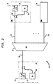
- Passive optical network 12 includes a central office 13 connected by a single fiber 20 to a remote node 22.
- Remote node 22 includes a wavelength router, preferentially, one such as the wavelength division multiplexing router (WDM/R) discussed above, which wavelength slices the downstream signal transmitted from central office 13. The sliced portions of the downstream signal are distributed along single fibers 24, to each of a number of optical network units 26.
- the central office 13 and each of the optical network units 26 contain coarse wavelength division multiplexing optical couplers 18, optical receivers 16 and LEDs 14, 28, respectively, for signal transmission/receipt.
- the coarse WDM couplers 18 located at the central office multiplex/demultiplex the downstream/upstream signals directed to/from the remote node via fiber 20. Distinct downstream and upstream wavelength bands are chosen to avoid reflection, crosstalk, etc., e.g., 1.3 um and 1.5 um, respectively.
- the WDM couplers 18 located at the optical network units multiplex/demultiplex the upstream/downstream information transmitted along fiber 24 to/from remote node 22.
- the expressions ⁇ dj and ⁇ uk describe the downstream and upstream wavelength bands, respectively.
- the j designation corresponds to ports on the downstream side of remote node 22, and the k designation corresponds to ports on the upstream side of the remote node.
- the wavelength division multiplexing router (WDM,R) contained therein insures that each downstream port j receives slices of the transmitted signal particular to the optical network unit to which it is directed.
- the periodicity of the wavelength division multiplexing router (WDM/R) insures that each port j receives a signal containing approximately the same optical power, assuming the wavelength spread of LED 14 is large relative to the router's (WDM/R's) free spectral range (FSR). That is, if there are N optical ports, ⁇ dj+mN is the wavelength band that will appear at port j for an integral m. If the FSR is small compared to ⁇ d , then each port j receives approximately the same power Pj.
- the entire optical signal generated within LED 28 is frequency selectively directed via each coarse WDM coupler 18 to the remote node 22.
- remote node 22 Due to the properties of the WDM/R, remote node 22 combines a sliced version of the LED spectrum generated within each optical network unit onto a single optical fiber and directs it to the central office. The sliced spectra are automatically interleaved such that the optical frequencies from distinct optical network units do not overlap, thereby preventing, for example, unwanted beat noise. Collisions of the signals broadcast from a plurality of optical network units are avoided at the central office by scheduling, by sub-carrier multiplexing (SCM), or by wavelength division multiplexing(WDM).
- SCM sub-carrier multiplexing
- WDM wavelength division multiplexing
- Scheduling is a form of time division multiplexing where, for example, different signals at the same from optical network units are delegated to predefined, calibrated time slots in accordance with a system clock.
- SCM is an arrangement where optical signals transmitted from each optical network unit or central office 13 are coded into unique RF subcarriers that modulate the LED 28 generated broadband light.
- WDM or WDM/R the signals are naturally segregated by wavelength and are therefore amenable to demultiplexing using a wavelength division multiplexer.
- the light received from the remote node is either segregated in time, as in the case of scheduling, or segregated by RF frequency, in the case of SCM, or by wavelength band in the case of WDM, and processed accordingly.
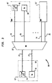
- Passive optical network 30 includes at least one central office 13' connected to a remote node 22' via at least two optical fibers 21 and 23.
- Fiber 21 forms a dedicated downstream path between remote node 22' and LED 14, and fiber 23 forms a dedicated upstream path between remote node 22' and receiver 16.
- a pair of fibers 25, 24, form dedicated downstream and upstream paths to receiver 16 and LED 28, respectively, thereby connecting the remote node to each of the plurality of optical network units 26' .
- the coarse WDM couplers 18 that were described above are not required within passive optical network 30 due to the presence of the dedicated upstream and downstream paths 25, 23, and 21, 24, respectively. While the two for one optical fiber requirement for this embodiment reduces the number of users which can be supported by each WDM/R-based remote node 22', implementation of such a network provides a vehicle for the implementation of future technologies directed towards formation of an efficient, high-performance network.
- a prototype of passive optical network 30 of Fig. 3 was built and tested at a baseband transmission of 40-Mb/s at various launched power levels.
- a 4x4 wavelength division multiplexing router (WDM/R) was used at the remote node 22' in the prototype, but connected to only one optical network unit 26' for simplicity in testing.
- Receiver 16 at optical network unit 26' was implemented with a commercially available AC-coupled PIN FET, which has a minimum optical power rating of -48 dBm at 40 Mb/sec.
- Figures 4A and 4B are display photos highlighting the optical spectra captured from LED 28 within optical network unit 26' at a wavelength band of 1.5 ⁇ m, and LED 14 within central office 13' at a wavelength band of 1.3 ⁇ m, respectively, during prototype testing.
- the signals generated within the LEDs are shown in each figure both before and after spectral slicing.
- the LEDs were directly modulated at 100% modulation depth with a non-return-to-zero (NRZ) pseudo-random data stream.
- Launched powers for each LED were varied from the LED's maximum rated value P L,max , down to a value resulting in a detected minimum power required for 1X10 ⁇ 9 BER P R,min .
- Electrical crosstalk generated by reflected light impinging on receivers was found to be neglible relative to receiver thermal noise during testing. It can be assumed, therefore, with such an arrangement, that the electrical crosstalk between dedicated upstream and downstream fibers leads to no appreciable performance degradation.
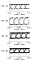
- Figures 5A and 5B each show received eye patterns for downstream and upstream transmission through the prototype during testing, respectively.
- Eye patterns are bit-train waveforms seen on a display, the time base of which is typically set to trigger at the bit rate of the transmitted (or broadcast) signal.
- the shape of the eye pattern gives the viewer an indication of both random (noise) and deterministic variations in the received signal which can give rise to errors.
- the wide open eyes in these figures are indicative of low error rate operation.
- the patterns correspond to maximum rated launched power levels of LEDs 14 and 28, respectively.
- the launched downstream power, P L, MAX , of LED 14 at Co 13' was measured at -13.3 dBm
- the launched upstream power, P L, MAX , of LED 28 at optical network unit 26' was measured at -17.5 dBm.
- the corresponding received powers were found to be -32.3 dBm and -34.5 dBm, respectively, at the downstream and upstream receivers, respectively.
- FIGs 6A and 6B show received eye patterns for downstream and upstream transmissions, respectively, after the launched LED power levels discussed in relation to Figures 5A and 5B were decreased by 10 dB within the prototype.
- the reduction of launched power by 10 dB was found to lower the received power levels to levels commensurate with power losses which would occur during actual field condition transmission.
- Figs. 6A and 6B are patterns derived from the wavelength division multiplexing router (WDM/R) at remote node 22' when optimized for 1.5 ⁇ m operation.
- the resulting downstream loss through the network was found to be 19 dB, exceeding the total upstream loss of 17 dB by 2dB.
- Six (6) of the 17 dB are due to the 1x4 split.
- 1 dB results from the connector and 10 dB from the wavelength division multiplexing router, i.e., 3 dB from chip loss, 2 dB from pigtails, 1 dB from polarization and 4 dB as a result of the filter function.
- a passive optical network architecture defined according to this invention provides a number of advantages over the prior art, most importantly, system implementation cost reductions. Because dedicated LEDs may be used for transmitting in both directions, the need for sources such as lasers operating at a discrete set of frequencies is avoided at both the central office and optical network units, and the need for modulators is avoided at the optical network units. Active components, e.g., LEDs and baseband receivers, which are readily available commercially at low cost, may be used in the network. Another benefit is the predicted ease with which the network architecture may be incrementally upgraded to incorporate advanced RITE-NetTM or LAR-NetTM features. Implementation of the passive optical network architecture described herein, therefore, promises a cost effective means for deploying fiber in the loop.
Abstract
A passive optical network is provided that spectrally slices optical signals transmitted in both upstream and downstream directions utilizing wavelength division multiplexing routing. The passive optical network preferably includes an incoherent signal source at both ends to provide signals that are spectrally sliced according to optical frequency. The downstream information may be transmitted in a conventional data format. The upstream transmissions may be segregated by subcarrier multiplexing, time scheduling or wavelength division multiplexing.
Description
- The present invention relates to a wavelengthdivision multiplexing passive optical network that utilizes bi-directional, optical spectral slicing for two-way transmission.
- Passive optical networks require no active components for directing optical signals between a central office or host digital terminal, and a network subscriber's terminal equipment. Passive optical networks, therefore, require no power or processing in the field to direct optically encoded information to its destination. Typically, a passive optical network includes a first fiber star formed as a plurality of optical paths extending from the central office to a remote node. Downstream optical signals are transmitted from the central office to the remote node, where the signal is passively split and distributed to one of a plurality of units of network subscriber equipment. The network units may transmit optically encoded signals upstream to the remote node to form a multiplexed signal for distribution to the central office. Lasers are generally used to generate light used to form the transmitted light signals.
- The present invention provides a wavelength division multiplexing passive optical network which utilizes incoherent light sources (e.g., LEDs) at both upstream and downstream transmitting locations. More particularly, the passive optical network of this invention includes a central office or host computer in optical commnication with one or more optical network units wherein both the central office and optical network units contain broadband incoherent sources and receivers for transmitting/receiving optical data. Optical data is routed to/from the optical network units via an optical routing coupler located at a remote node, a wavelength division multiplexer (WDM) or preferably, a wavelength division multiplexing router (WDM/R). The wavelength division multiplexing router spectrally slices and distributes received light by wavelength, or, spectrally combines selected portions of the broadband spectrum, depending on broadcast direction. The upstream and downstream signal sources may transmit at separate wavelength bands, e.g., 1.3µm and 1.5µm, respectively.
- Due to the varying distances between the remote node and the optical network units, collisions at the central office among the various received signals are possible. These collisions are avoided within the invention by either scheduling (time segregation) of optical network transmissions (i.e., time division multiplexing TDM) or subcarrier multiplexing (SCM) or wavelength division multiplexing. The optical network may be implemented in either a single-fiber or dual-fiber configuration. In the single-fiber configuration, a single fiber is used to optically connect the central office to the remote node, and to optically connect the remote node to each optical network unit. In the dual-fiber configuration, separate fibers for upstream and downstream transmission at both ends of the remote node are employed.
- Downstream information, i.e., optical information provided by the central office, transmitted with a broadband source such as an LED or an erbium-doped fiber amplifier, in lieu of a conventional multi-wavelength source, such as a laser, offers several advantages. First, spectral slicing of a signal generated within a broadband signal source permits transmitting in a broadcast mode. One advantage of LEDs is that they are a more mature technology and therefore more cost effective than lasers. Accordingly, sources and detectors are readily available at present for deployment as an FITH for low cost. By using LEDs at both ends of a passive optical network, technological implementation can take place now without the need to wait for development of economical multiwavelength sources. Finally, implementation of the present network is compatible with RITE-Net™ design for compatibility with future upgrades.
- A standard passive optical network model is shown in Figure 1, consisting of a
first fiber star 1, typically a plurality ofoptical fibers 2 extending from a central office 4, to one of a plurality ofremote nodes 6, i.e., RN₁, RN₂, .... RNN. Downstream signals are transmitted from the central office towards the remote node for further distribution. At the remote nodes, light is passively split and distributed via a plurality of optical fibers 8 (a second star) to a plurality ofoptical network units 10, i.e., ONU₁, ONU₂, ... ONUN. The optical network units provide service to one or more end users wherein each downstream optical signal is received and electronically distributed to end users. Theoptical network units 10 may transmit upstream signals which are combined at the remote node. Each remote node 6 (or passive star) passively combines transmissions from theoptical network units 10 onto singleoptical fiber 2 for distribution to the central office. Stern, et al., PASSIVE OPTICAL LOCAL NETWORKS FOR TELEPHONE APPLICATIONS AND BEYOND, ELECTRON LETTERS, vol. 23, pgs. 1255-57 (1987). - Two passive optical network architectures which will be discussed herein are telephony over passive optical networks (TPON) and wavelength division multiplexing passive optical networks (WDM PONs). In a TPON architecture, a central office broadcasts a downstream optical signal to all optical network units using time-division multiplexing (TDM) protocol. A laser with a common wavelength band, requiring synchronization, may also be used. TDM typically includes a frame of information subdivided into time slots assigned to individual optical network units. Wavelength division multiplexing passive optical networks utilize an architecture within which each optical network unit or subscriber is assigned a unique wavelength by the central office. Signals destined for each remote node (and ultimately, each optical network unit) are created by modulating light at N distinct wavelengths at the central office. The modulated light is multiplexed onto a fiber directed to the remote node. The downstream signals are split and distributed to the optical network unit as a function of wavelength within a wavelength division demultiplexer (WDM) at the remote node. In the upstream transmission direction (optical network unit to remote node), the light is transmitted at assigned wavelengths, typically by laser.
- RITE-Net™ is one type of wavelength division multiplexing passive optical network that uses a wavelength division multiplexing router (WDM/R) at the remote node, which distinguishes it from a conventional wavelength division multiplexing passive optical network. Wavelength division multiplexing router couplers are described in a paper by Dragone, An NxN Optical Multiplexer Using a Planer Arrangement of Two Star Couplers, IEEE Phot. Technol. Lett. Within the RITE-Net™ architecture, a multiwavelength laser at the central office sends multiplexed optical signals encoded with data at specific wavelengths to the remote node. At the remote node, the downstream signals are routed by the wavelength division multiplexing router according to wavelength to the optical network units. The separation between frequencies of the WDM/R (mode spacing) sets the system's channel spacing. The central office transmitter is designed such that its mode spacing closely matches that of the WDM/R. An electronic sequencer and a control circuit define the central office transmitter wavelength and insure that data signals modulate the transmitter when lasing at particular wavelengths. At the optical network unit, a portion of the received light is overmodulated with subscriber data and looped back through the remote node to the central office. That is, a modulator at the optical network unit imprints upstream information on a CW portion of the downstream signal which is then directed back to the remote node. Such a network is referred to as a RITE-Net™ network, as described in EP-A-0 615 358.
- In LAR-Net™, another wavelength division multiplexing passive optical network, the need for the RITE-Net™ modulator at the ONU is avoided. Multi-frequency signals are sent from the central office (where a multi-frequency signal source and receiver are located) over single fibers to a remote node for routing by wavelength to different optical network units. A coupler at the optical network unit combines/separates upstream and downstream traffic, directing the downstream traffic to a receiver. A broadband incoherent signal source, such as an LED, is provided for transmitting upstream communications, replacing the RITE-Net™ modulators. The upstream signal is spectrally sliced at the remote node (i.e., the wavelength division multiplexing router) into appropriate wavelength bands to prevent spectral overlap of upstream signals. LAR-Net™ network is described in commonly-owned U.S. Patent Appln. Serial No. 08/261,5844, filed June 17, 1994, and incorporated herein by reference.
- Variations on the Zirngibl method have been implemented. Reeve et al., LED Spectral Slicing for Single-mode Local Loop Applications, Electronic Letters, vol. 24, no. 7, pgs. 389-90 (1988), discloses a system within which each subscriber receives a dedicated wavelength channel comprising different wavelength slices from the spectrum of identical LEDs. The system utilizes two wavelength division multiplexing couplers to implement the spectral slicing. A second variation is disclosed by Wagner et al., Experimental Demonstration of a Passive Optical Subscriber Loop Architecture, Electronic Letters, vol. 24, no. 6, pgs. 244-45 (1988). A system is disclosed therein that employs multichannel wavelength division multiplexing technique to provide each subscriber with a dedicated channel to/from the central office. Transmission has been found to be successful at received levels of -55 dBm.
- One embodiment of a wavelength division multiplexing passive optical network with bi-directional optical
spectral splicing 12 of this invention is shown in Figure 2. Passiveoptical network 12 includes acentral office 13 connected by asingle fiber 20 to aremote node 22.Remote node 22 includes a wavelength router, preferentially, one such as the wavelength division multiplexing router (WDM/R) discussed above, which wavelength slices the downstream signal transmitted fromcentral office 13. The sliced portions of the downstream signal are distributed alongsingle fibers 24, to each of a number ofoptical network units 26. Thecentral office 13 and each of theoptical network units 26 contain coarse wavelength division multiplexingoptical couplers 18,optical receivers 16 andLEDs 14, 28, respectively, for signal transmission/receipt. Thecoarse WDM couplers 18 located at the central office multiplex/demultiplex the downstream/upstream signals directed to/from the remote node viafiber 20. Distinct downstream and upstream wavelength bands are chosen to avoid reflection, crosstalk, etc., e.g., 1.3 um and 1.5 um, respectively. The WDM couplers 18 located at the optical network units multiplex/demultiplex the upstream/downstream information transmitted alongfiber 24 to/fromremote node 22. When used herein, the expressions λdj and λuk describe the downstream and upstream wavelength bands, respectively. The j designation corresponds to ports on the downstream side ofremote node 22, and the k designation corresponds to ports on the upstream side of the remote node. - When a downstream signal arrives at
remote node 22, the wavelength division multiplexing router (WDM,R) contained therein insures that each downstream port j receives slices of the transmitted signal particular to the optical network unit to which it is directed. The periodicity of the wavelength division multiplexing router (WDM/R) insures that each port j receives a signal containing approximately the same optical power, assuming the wavelength spread of LED 14 is large relative to the router's (WDM/R's) free spectral range (FSR). That is, if there are N optical ports, λdj+mN is the wavelength band that will appear at port j for an integral m. If the FSR is small compared to Δλd, then each port j receives approximately the same power Pj. Each Pj is equal to the scaled central office output power (Po) over N, i.e., Pj=αPo/N, where α is a constant that incorporates various sources of excess loss. In contrast, only λdj will appear at port j in a conventional WDM, i.e., only for m=0, resulting in a lower value of Pj. - In the upstream transmission direction, the entire optical signal generated within LED 28 (at each optical network unit 26) is frequency selectively directed via each
coarse WDM coupler 18 to theremote node 22. Due to the properties of the WDM/R,remote node 22 combines a sliced version of the LED spectrum generated within each optical network unit onto a single optical fiber and directs it to the central office. The sliced spectra are automatically interleaved such that the optical frequencies from distinct optical network units do not overlap, thereby preventing, for example, unwanted beat noise. Collisions of the signals broadcast from a plurality of optical network units are avoided at the central office by scheduling, by sub-carrier multiplexing (SCM), or by wavelength division multiplexing(WDM). Scheduling is a form of time division multiplexing where, for example, different signals at the same from optical network units are delegated to predefined, calibrated time slots in accordance with a system clock. SCM is an arrangement where optical signals transmitted from each optical network unit orcentral office 13 are coded into unique RF subcarriers that modulate theLED 28 generated broadband light. By construction of the WDM or WDM/R, the signals are naturally segregated by wavelength and are therefore amenable to demultiplexing using a wavelength division multiplexer. At the central office, the light received from the remote node is either segregated in time, as in the case of scheduling, or segregated by RF frequency, in the case of SCM, or by wavelength band in the case of WDM, and processed accordingly. - A second embodiment of this invention, a passive
optical network 30, is shown in Figure 3. Passiveoptical network 30 includes at least onecentral office 13' connected to a remote node 22' via at least twooptical fibers Fiber 21 forms a dedicated downstream path between remote node 22' and LED 14, andfiber 23 forms a dedicated upstream path between remote node 22' andreceiver 16. On the downstream side of remote node 22' , a pair offibers receiver 16 andLED 28, respectively, thereby connecting the remote node to each of the plurality of optical network units 26' . Thecoarse WDM couplers 18 that were described above are not required within passiveoptical network 30 due to the presence of the dedicated upstream anddownstream paths - A prototype of passive
optical network 30 of Fig. 3 was built and tested at a baseband transmission of 40-Mb/s at various launched power levels. A 4x4 wavelength division multiplexing router (WDM/R) was used at the remote node 22' in the prototype, but connected to only one optical network unit 26' for simplicity in testing.Receiver 16 at optical network unit 26' was implemented with a commercially available AC-coupled PIN FET, which has a minimum optical power rating of -48 dBm at 40 Mb/sec. - Figures 4A and 4B are display photos highlighting the optical spectra captured from
LED 28 within optical network unit 26' at a wavelength band of 1.5µm, and LED 14 withincentral office 13' at a wavelength band of 1.3 µm, respectively, during prototype testing. The signals generated within the LEDs are shown in each figure both before and after spectral slicing. The LEDs were directly modulated at 100% modulation depth with a non-return-to-zero (NRZ) pseudo-random data stream. Launched powers for each LED were varied from the LED's maximum rated value PL,max, down to a value resulting in a detected minimum power required for 1X10⁻⁹ BER PR,min. Electrical crosstalk generated by reflected light impinging on receivers was found to be neglible relative to receiver thermal noise during testing. It can be assumed, therefore, with such an arrangement, that the electrical crosstalk between dedicated upstream and downstream fibers leads to no appreciable performance degradation. - Figures 5A and 5B each show received eye patterns for downstream and upstream transmission through the prototype during testing, respectively. Eye patterns are bit-train waveforms seen on a display, the time base of which is typically set to trigger at the bit rate of the transmitted (or broadcast) signal. The shape of the eye pattern gives the viewer an indication of both random (noise) and deterministic variations in the received signal which can give rise to errors. The wide open eyes in these figures are indicative of low error rate operation. The patterns correspond to maximum rated launched power levels of
LEDs 14 and 28, respectively. The launched downstream power, PL, MAX, of LED 14 atCo 13' was measured at -13.3 dBm, and the launched upstream power, PL, MAX, ofLED 28 at optical network unit 26' was measured at -17.5 dBm. The corresponding received powers were found to be -32.3 dBm and -34.5 dBm, respectively, at the downstream and upstream receivers, respectively. - Figures 6A and 6B show received eye patterns for downstream and upstream transmissions, respectively, after the launched LED power levels discussed in relation to Figures 5A and 5B were decreased by 10 dB within the prototype. The reduction of launched power by 10 dB was found to lower the received power levels to levels commensurate with power losses which would occur during actual field condition transmission. Figs. 6A and 6B are patterns derived from the wavelength division multiplexing router (WDM/R) at remote node 22' when optimized for 1.5µm operation. The resulting downstream loss through the network was found to be 19 dB, exceeding the total upstream loss of 17 dB by 2dB. Six (6) of the 17 dB are due to the 1x4 split. Of the remaining 11 dB loss, 1 dB results from the connector and 10 dB from the wavelength division multiplexing router, i.e., 3 dB from chip loss, 2 dB from pigtails, 1 dB from polarization and 4 dB as a result of the filter function.
- While power loss within transmitted signals is particularly relevant, another factor critical to transmission within a passive optical network is chromatic dispersion. In order to identify signal degradation due to chromatic dispersion, the upstream and downstream prototype transmission paths were implemented in the prototype with conventional single mode fibers that display a zero-dispersion value at 1.3µm, i.e., λo equals 1.3µm. At 1.5µm transmission, the dispersion value was found to be 16ps/(nm-km). Figures 7A and 7B show the combined effects of loss and dispersion, due to transmission through 8 km of the conventional signal mode fiber in the upstream and downstream directions, respectively, within the prototype. The launched powers were equal to -17.5 dBm and dBm -13.3 dBm, respectively. As the tests results indicate, the eyes remained open, with only slight evidence of distortion due to chromatic distortion, as seen in a comparison of the figures.
- It follows that a passive optical network architecture defined according to this invention provides a number of advantages over the prior art, most importantly, system implementation cost reductions. Because dedicated LEDs may be used for transmitting in both directions, the need for sources such as lasers operating at a discrete set of frequencies is avoided at both the central office and optical network units, and the need for modulators is avoided at the optical network units. Active components, e.g., LEDs and baseband receivers, which are readily available commercially at low cost, may be used in the network. Another benefit is the predicted ease with which the network architecture may be incrementally upgraded to incorporate advanced RITE-Net™ or LAR-Net™ features. Implementation of the passive optical network architecture described herein, therefore, promises a cost effective means for deploying fiber in the loop.
- What has been described herein is merely illustrative of one or more particular applications of the principals of the present invention. Other arrangements and methods may be implemented, however, by those skilled in the art without departing from the scope of this invention.
Claims (16)
- A passive optical network utilizing bi-directional optical spectral slicing, comprising:a) a central office for transmitting/receiving optical information;b) a remote node optically linked to said central office for routing said optical information by wavelength band by said spectral slicing; andc) at least one optical network unit optically linked to said remote node for transmitting/receiving said optical information, wherein said central office transmits optical information as downstream data signals to said remote node, and said remote node optically routes said downstream data signals to each said optical network unit according to wavelength bands, and wherein said optical network unit transmits upstream data signals to said remote node, and said remote node optically routes, according to wavelength bands, said upstream data signals to said central office.
- The passive optical network defined by claim 1, wherein said remote node includes a wavelength division multiplexing routing coupler (WDM/R).
- The passive optical network defined by claim 2, wherein said central office and said optical network unit include an incoherent optical signal source and an optical signal receiver.
- The passive optical network defined by claim 3, wherein said remote node is optically linked to said central office and said optical network unit, respectively, via a single upstream and a single downstream fiber.
- The passive optical network defined by claim 1, wherein said incoherent optical signal source at said central office operates at a different wavelength band than the wavelength band of said optical network units.
- The passive optical network defined by claim 4, wherein each fiber is a single mode fiber.
- The passive optical network defined by claim 3, wherein said central office is optically linked to said remote node, and said remote node is optically linked to said optical network unit, via single fiber paths for two-way transmission.
- The passive optical network defined by claim 7, wherein said optical network unit and said central office each include coarse wavelength division multiplexing means.
- The passive optical network defined by claim 7, wherein said fiber is a single mode fiber.
- The passive optical network defined by claim 1, wherein each said optical network unit includes means for RF subcarrier modulating said upstream data signals and said central office includes means for segregating said received upstream data signals according to RF sub-carrier frequency.
- The passive optical network defined by claim 1, wherein each said optical network unit includes means for time scheduling said upstream data signals and said central office includes means for time segregating said received upstream data signals according to time.
- A method for optically linking a central communications location and at least one remote communications location in which optical information signals transmitted to/from said central location and to/from said remote location, respectively, are spectrally sliced, comprising the steps of:a) first transmitting and receiving optical data signals at said central location;b) second transmitting and receiving optical data signals at said remote location; andc) routing said data signals to/from said central location and to/from said remote location, wherein said routing includes spectrally slicing of said optical data signals into wavelength bands.
- The method of claim 12, wherein said step of first transmitting includes generating said optical data signals with an incoherent light signal source.
- The method of claim 12, wherein said step of second transmitting includes generating said optical data signals with an incoherent light signal source.
- The method of claim 12, wherein said steps of first and second transmitting includes transmitting said signals via two-way, single fiber paths.
- The method of claim 15, wherein said steps of first and second transmitting includes transmitting in different wavelength bands.
Applications Claiming Priority (2)
| Application Number | Priority Date | Filing Date | Title |
|---|---|---|---|
| US32657694A | 1994-10-20 | 1994-10-20 | |
| US326576 | 1994-10-20 |
Publications (1)
| Publication Number | Publication Date |
|---|---|
| EP0708540A1 true EP0708540A1 (en) | 1996-04-24 |
Family
ID=23272811
Family Applications (1)
| Application Number | Title | Priority Date | Filing Date |
|---|---|---|---|
| EP95307186A Withdrawn EP0708540A1 (en) | 1994-10-20 | 1995-10-11 | A wavelength division multiplexing passive optical network with bi-directional optical spectral slicing |
Country Status (4)
| Country | Link |
|---|---|
| US (3) | US5680234A (en) |
| EP (1) | EP0708540A1 (en) |
| JP (1) | JPH08237223A (en) |
| CA (1) | CA2160823C (en) |
Cited By (4)
| Publication number | Priority date | Publication date | Assignee | Title |
|---|---|---|---|---|
| EP0829981A2 (en) * | 1996-09-13 | 1998-03-18 | Lucent Technologies Inc. | System and method for mitigating cross-saturation in optically amplified networks |
| WO1998013963A1 (en) * | 1996-09-24 | 1998-04-02 | At & T Corp. | A multiplicity of services via a wavelength division router |
| EP0845842A1 (en) * | 1996-12-02 | 1998-06-03 | Koninklijke KPN N.V. | Optical system with one or more stabilised laser signal sources |
| CN112242871A (en) * | 2019-07-19 | 2021-01-19 | 上海诺基亚贝尔股份有限公司 | Method, apparatus and computer-readable storage medium for optical communication |
Families Citing this family (140)
| Publication number | Priority date | Publication date | Assignee | Title |
|---|---|---|---|---|
| US6108113A (en) * | 1995-12-29 | 2000-08-22 | Mci Communications Corporation | Method and system for transporting ancillary network data |
| US5864413A (en) * | 1996-02-23 | 1999-01-26 | Lucent Technologies, Inc. | Passive optical network for dense WDM downstream data transmission and upstream data transmission |
| WO1998009397A1 (en) * | 1996-08-27 | 1998-03-05 | At & T Corp. | Simultaneous wavelength-division multiplexing and broadcast transmission system |
| US6552832B1 (en) * | 1996-10-07 | 2003-04-22 | Telesector Resources Group, Inc. | Telecommunications system including transmultiplexer installed between digital switch and optical signal transmission fiber |
| US5880865A (en) * | 1996-12-03 | 1999-03-09 | Lucent Technologies Inc. | Wavelength-division-multiplexed network having broadcast capability |
| FI103619B (en) | 1997-05-26 | 1999-07-30 | Nokia Telecommunications Oy | Optical multiplexing and demultiplexing |
| US6072612A (en) * | 1997-08-08 | 2000-06-06 | Lucent Technologies, Inc. | WDM transmitter for optical networks using a loop-back spectrally sliced light emitting device |
| US6631018B1 (en) * | 1997-08-27 | 2003-10-07 | Nortel Networks Limited | WDM optical network with passive pass-through at each node |
| US6041152A (en) * | 1997-09-02 | 2000-03-21 | Amphenol Corporation | Multi-channel fiber optic communications system and multiplexer/demultiplexer arrangement therefor |
| US6144472A (en) * | 1998-01-20 | 2000-11-07 | Lucent Technologies Inc. | Upgrading a power-splitting passive optical network using optical filtering |
| US6151144A (en) * | 1998-01-20 | 2000-11-21 | Lucent Technologies, Inc. | Wavelength division multiplexing for unbundling downstream fiber-to-the-home |
| US6137608A (en) * | 1998-01-30 | 2000-10-24 | Lucent Technologies Inc. | Optical network switching system |
| CA2262248A1 (en) | 1998-02-18 | 1999-08-18 | At&T Corp. | Long reach delivery of broadcast services using broadband optical sources and pre-compensation of dispersion |
| US6577414B1 (en) | 1998-02-20 | 2003-06-10 | Lucent Technologies Inc. | Subcarrier modulation fiber-to-the-home/curb (FTTH/C) access system providing broadband communications |
| JPH11275028A (en) * | 1998-03-20 | 1999-10-08 | Fujitsu Ltd | Optical communication system |
| US5943457A (en) * | 1998-03-24 | 1999-08-24 | Telecommunications Research Laboratories | Generalized resonant coupler filters |
| US6650840B2 (en) * | 1998-03-27 | 2003-11-18 | Lucent Technologies Inc. | Method for identifying faults in a branched optical network |
| US6381047B1 (en) | 1998-05-06 | 2002-04-30 | At&T Corp. | Passive optical network using a fabry-perot laser as a multiwavelength source |
| US6014237A (en) * | 1998-06-01 | 2000-01-11 | Sarnoff Corporation | Multiwavelength mode-locked dense wavelength division multiplexed optical communication systems |
| US6388782B1 (en) | 1998-06-01 | 2002-05-14 | Sarnoff Corporation | Multi-wavelength dense wavelength division multiplexed optical switching systems |
| IT1301848B1 (en) * | 1998-07-23 | 2000-07-07 | Sirti Spa | PASSIVE SYSTEM FOR SURVEILLANCE OF OPTICAL DISTRIBUTION NETWORKS WITH TREE STRUCTURE |
| US6366713B1 (en) * | 1998-09-04 | 2002-04-02 | Tellabs Operations, Inc. | Strictly non-blocking optical switch core having optimized switching architecture based on reciprocity conditions |
| US6192058B1 (en) | 1998-09-18 | 2001-02-20 | Sarnoff Corporation | Multiwavelength actively mode-locked external cavity semiconductor laser |
| DE19909565A1 (en) * | 1999-03-04 | 2000-10-05 | Siemens Ag | Process for monitoring the operation of optical fibers |
| AU5030300A (en) * | 1999-05-28 | 2000-12-18 | Advanced Fibre Communications, Inc. | Wdm passive optical network with broadcast overlay |
| US6192172B1 (en) | 1999-08-09 | 2001-02-20 | Lucent Technologies Inc. | Optical wavelength-space cross-connect switch architecture |
| US6583867B1 (en) * | 1999-08-13 | 2003-06-24 | Fitel Usa Corp. | System and method for monitoring optical fiber integrity between the telecommunications provider and a customer's premises |
| US6498667B1 (en) * | 1999-09-10 | 2002-12-24 | Quantum Bridge Communications, Inc. | Method and system for packet transmission over passive optical network |
| KR100337131B1 (en) * | 1999-10-14 | 2002-05-18 | 윤덕용 | Bi-directional, subcarrier-multiplexed self-healing ring optical network |
| KR100325687B1 (en) * | 1999-12-21 | 2002-02-25 | 윤덕용 | A low-cost WDM source with an incoherent light injected Fabry-Perot semiconductor laser diode |
| JP2001223642A (en) * | 2000-02-09 | 2001-08-17 | Sumitomo Electric Ind Ltd | Optical communication unit |
| JP2001339348A (en) * | 2000-05-26 | 2001-12-07 | Nec Corp | Photocoupler monitor system |
| US6850662B1 (en) | 2000-07-31 | 2005-02-01 | Tellabs Operations, Inc. | Optical switch for reciprocal traffic |
| US6363182B2 (en) | 2000-07-31 | 2002-03-26 | James D. Mills | Optical switch for reciprocal traffic |
| US7079768B2 (en) | 2000-10-03 | 2006-07-18 | Lucent Technologies Inc. | Dynamic passive optical network (PON) using a distributed optical cross connect and dense wavelength division multiplexing |
| US6868233B2 (en) * | 2000-12-14 | 2005-03-15 | Alcatel Usa Sourcing, L.P. | Wavelength agile optical transponder for bi-directional, single fiber WDM system testing |
| DE10102144C2 (en) * | 2001-01-18 | 2003-02-13 | Infineon Technologies Ag | Broadband optical transmission device |
| US6771908B2 (en) * | 2001-02-12 | 2004-08-03 | Lucent Technologies Inc. | Fast protection switching by snooping on downstream signals in an optical network |
| US6778781B2 (en) | 2001-02-12 | 2004-08-17 | Lucent Technologies Inc. | Health check algorithm for protection circuit in optical network |
| US6868232B2 (en) * | 2001-02-12 | 2005-03-15 | Lucent Technologies Inc. | Fast protection switching by snooping on upstream signals in an optical network |
| US20020131125A1 (en) * | 2001-03-16 | 2002-09-19 | Myers Michael H. | Replicated-spectrum photonic transceiving |
| US20020131106A1 (en) | 2001-03-16 | 2002-09-19 | Peter Snawerdt | Secure wave-division multiplexing telecommunications system and method |
| US6407846B1 (en) | 2001-03-16 | 2002-06-18 | All Optical Networks, Inc. | Photonic wavelength shifting method |
| US7127167B2 (en) * | 2001-07-05 | 2006-10-24 | Broadcom Corporation | System for spectrum allocation in ethernet-based fiber optic TDMA networks |
| US7620327B2 (en) * | 2001-07-09 | 2009-11-17 | Oyster Optics, Inc. | Fiber optic telecommunications card with energy level monitoring |
| KR100735692B1 (en) * | 2001-07-12 | 2007-07-06 | 엘지전자 주식회사 | Code modulation method for using adaptive modulation and acknowledge |
| US7155127B2 (en) | 2001-08-15 | 2006-12-26 | Nippon Telegraph And Telephone Corporation | Optical communication system, optical communication unit, and optical transceiving package |
| US20030128718A1 (en) * | 2001-10-10 | 2003-07-10 | Matthews Paul J. | Method for switching and routing large bandwidth continuous data streams from a centralized location |
| US7236708B2 (en) * | 2001-10-25 | 2007-06-26 | Nippon Telegraph And Telephone Corporation | Optical communication system with optical output level control function |
| US20040208545A1 (en) * | 2001-12-13 | 2004-10-21 | Ali Langari | Optical switch with enhanced flexibility |
| FI20012570A0 (en) * | 2001-12-21 | 2001-12-21 | Nokia Corp | Optical transmission network |
| KR100496710B1 (en) * | 2002-01-21 | 2005-06-28 | 노베라옵틱스코리아 주식회사 | Bi-directional wavelength-division-multiplexing passive optical network utilizing wavelength-locked light sources by injected incoherent light |
| US7058301B2 (en) | 2002-02-28 | 2006-06-06 | Bosloy Jonathan L | Apparatus and method for planned wavelength addition and removal in a wavelength division multiplexed system |
| US20030216945A1 (en) * | 2002-03-25 | 2003-11-20 | Dvorak Carl D. | Method for analyzing orders and automatically reacting to them with appropriate responses |
| US7181142B1 (en) | 2002-04-09 | 2007-02-20 | Time Warner Cable Inc. | Broadband optical network apparatus and method |
| US6873763B2 (en) * | 2002-04-12 | 2005-03-29 | Intel Corporation | Managing channels with different wavelengths in optical networks |
| US6678442B2 (en) * | 2002-04-24 | 2004-01-13 | Pangrac And Associates Development, Inc. | Fiber optic connector for a segmented FTTH optical network |
| KR100515259B1 (en) | 2002-05-03 | 2005-09-15 | 한국과학기술원 | Wavelength-tunable light source and wavelength-division multiplexed transmission system with the sources |
| FR2841414B1 (en) * | 2002-06-20 | 2004-12-10 | Cit Alcatel | OPTICAL RING NETWORK WITH DECOUPLED READING AND WRITING FIBERS |
| US8750702B1 (en) * | 2002-06-21 | 2014-06-10 | Rockstar Consortium Us Lp | Passive optical loopback |
| KR100606102B1 (en) * | 2002-08-03 | 2006-07-28 | 삼성전자주식회사 | Broadcast/communication unified passive optical network system |
| KR100514383B1 (en) * | 2002-08-06 | 2005-09-13 | 최준국 | Wavelength division multiplexing-passive optical network using same wavelength as upstream and downstream chanel |
| US7593647B2 (en) * | 2002-09-19 | 2009-09-22 | Novera Optics, Inc. | Apparatuses and methods for automatic wavelength locking of an optical transmitter to the wavelength of an injected incoherent light signal |
| KR100489922B1 (en) * | 2002-10-01 | 2005-05-17 | 최준국 | Dense wavelength division multiplexing-passive optical network using self-injection locking of fabry-perot laser diode |
| KR100480246B1 (en) * | 2002-11-07 | 2005-04-07 | 삼성전자주식회사 | Passive optical network using loop back of multi-wavelength light generated at central office |
| KR100473520B1 (en) | 2002-12-24 | 2005-03-10 | 한국과학기술원 | The optical access network using wavelength-locked WDM optical source injected by incoherent light |
| US7203422B2 (en) * | 2002-12-26 | 2007-04-10 | Nippon Telegraph And Telephone Corporation | Optical network unit, wavelength splitter, and optical wavelength-division multiplexing access system |
| GB0311563D0 (en) * | 2003-05-20 | 2003-06-25 | Nokia Corp | Optical data transmission system |
| US7515626B2 (en) * | 2003-05-29 | 2009-04-07 | Novera Optics, Inc. | Light source capable of lasing that is wavelength locked by an injected light signal |
| KR100955129B1 (en) | 2003-05-30 | 2010-04-28 | 정보통신연구진흥원 | wavelength-division multiple access passive optical network using the incoherent broadband light source |
| KR100547709B1 (en) * | 2003-07-07 | 2006-01-31 | 삼성전자주식회사 | Self-Healing Wavelength Division Multiplexing Passive Optical Subscriber Network |
| US7062171B2 (en) * | 2003-07-15 | 2006-06-13 | Yusuke Ota | Multi-wavelength, bi-directional optical multiplexer |
| KR100547797B1 (en) * | 2003-07-28 | 2006-01-31 | 삼성전자주식회사 | Wavelength Division Multiplexing Passive Optical Subscriber Network Using Multi-wavelength Raising Light Source and Reflective Optical Amplification |
| FR2859054B1 (en) * | 2003-08-19 | 2006-12-29 | Cit Alcatel | DYNAMIC CONTROL OF LOSS OF POWER IN AN OPTICAL FIBER BY CONTRAPROPAGATION OF A SUPERVISORY CHANNEL |
| KR100594075B1 (en) * | 2003-09-26 | 2006-06-30 | 삼성전자주식회사 | Ethernet Passive Optical Network for Convergence of Broadcasting and Telecommunication By Using Time Dividing Multiplex |
| KR100575953B1 (en) * | 2003-10-27 | 2006-05-02 | 삼성전자주식회사 | Optical signal transmitter with reflective gain clamped semiconductor optical amplifier and optical communicating system using thereof |
| US7313157B2 (en) * | 2003-12-19 | 2007-12-25 | Novera Optics, Inc. | Integration of laser sources and detectors for a passive optical network |
| KR20050070566A (en) * | 2003-12-30 | 2005-07-07 | 삼성전자주식회사 | Multi-wavelength light source and wavelength-division multiplexing system using the same |
| CA2580852A1 (en) * | 2004-09-21 | 2006-03-30 | Synta Pharmaceutical Corp. | Compounds for inflammation and immune-related uses |
| KR100608946B1 (en) * | 2004-10-20 | 2006-08-03 | 광주과학기술원 | Wdm-pon by using self-injection locked fabry-perot laser diode, remote node, and control method therefor |
| US7680388B2 (en) * | 2004-11-03 | 2010-03-16 | Adc Telecommunications, Inc. | Methods for configuring and testing fiber drop terminals |
| US20060147203A1 (en) * | 2004-12-30 | 2006-07-06 | Thinguldstad Arthur M | Optical network element with remote access capability |
| KR100678257B1 (en) * | 2005-01-12 | 2007-02-02 | 삼성전자주식회사 | Hybrid passive optical network |
| KR100678256B1 (en) * | 2005-01-12 | 2007-02-02 | 삼성전자주식회사 | Wavelength division multiplexing passive optical network |
| US20060153566A1 (en) * | 2005-01-13 | 2006-07-13 | Sorin Wayne V | Methods and apparatuses to provide a wavelength-division-multiplexing passive optical network with asymmetric data rates |
| KR100703470B1 (en) | 2005-04-18 | 2007-04-03 | 삼성전자주식회사 | Wavelength division multiplexed light source and passive optical network using the same |
| CN101160542B (en) | 2005-04-19 | 2010-10-13 | Adc电信公司 | Loop back plug and method |
| US7266265B2 (en) * | 2005-05-02 | 2007-09-04 | Pangrac & Associates Development, Inc. | Low-loss shared FTTH distribution network |
| US7362931B2 (en) * | 2005-05-02 | 2008-04-22 | Pangrac & Associates Development, Inc. | Optical conversion device for shared FTTH distribution network |
| DE102005028844B4 (en) * | 2005-06-22 | 2007-07-05 | Luk Lamellen Und Kupplungsbau Beteiligungs Kg | Method and device for controlling a non-self-locking coupling |
| KR100640485B1 (en) | 2005-07-26 | 2006-10-30 | 삼성전자주식회사 | Bidirectional optical passive network |
| KR100711201B1 (en) | 2005-08-09 | 2007-04-24 | 한국과학기술원 | The long-reach wavelength division multiplexing passive optical networks by using the position adjustment of broadband light source |
| KR100698766B1 (en) | 2005-09-07 | 2007-03-23 | 한국과학기술원 | Apparatus for Monitoring Failure Positions in Wavelength Division Multiplexing-Passive Optical Networks and Wavelength Division Multiplexing-Passive Optical Network Systems Having the Apparatus |
| KR100785436B1 (en) * | 2005-09-20 | 2007-12-13 | 한국과학기술원 | Wavelength division multiplexing passive optical network for convergence broadcasting service and communication service |
| US7499651B2 (en) * | 2005-10-20 | 2009-03-03 | Fujitsu Limited | Upgradeable passive optical network |
| US8023823B2 (en) * | 2005-10-20 | 2011-09-20 | Fujitsu Limited | System and method for transmitting upstream traffic in an optical network |
| US7653309B2 (en) * | 2005-10-20 | 2010-01-26 | Fujitsu Limited | System and method for distributing traffic in an optical network |
| US7546036B2 (en) * | 2005-10-20 | 2009-06-09 | Fujitsu Limited | Hybrid passive optical network using shared wavelengths |
| US7522838B2 (en) * | 2005-10-20 | 2009-04-21 | Fujitsu Limited | Distribution components for a wavelength-sharing network |
| US7684705B2 (en) * | 2005-10-20 | 2010-03-23 | Fujitsu Limited | Distribution node for a wavelength-sharing network |
| US7684706B2 (en) * | 2005-10-20 | 2010-03-23 | Fujitsu Limited | System and method for traffic distribution in an optical network |
| US7324922B2 (en) * | 2005-10-26 | 2008-01-29 | International Business Machines Corporation | Run-time performance verification system |
| FR2893469B1 (en) * | 2005-11-17 | 2007-12-14 | Alcatel Sa | IMPROVED DATA TRANSMISSION DEVICES FOR COMMUNICATION EQUIPMENT OF A PASSIVE OPTICAL NETWORK |
| US7440701B2 (en) * | 2005-12-13 | 2008-10-21 | Broadway Networks, Ltd. | Fiber-to-the-premise optical communication system |
| US7639946B2 (en) * | 2006-01-06 | 2009-12-29 | Fujitsu Limited | Distribution node for an optical network |
| US7603036B2 (en) * | 2006-01-06 | 2009-10-13 | Fujitsu Limited | System and method for managing network components in a hybrid passive optical network |
| US8180223B2 (en) * | 2006-02-03 | 2012-05-15 | Fujitsu Limited | System and method for extending reach in a passive optical network |
| US7450848B2 (en) * | 2006-04-28 | 2008-11-11 | Broadway Networks, Ltd, | High-speed fiber-to-the-premise optical communication system |
| US20070280690A1 (en) * | 2006-06-02 | 2007-12-06 | Fujitsu Limited | System and Method for Managing Power in an Optical Network |
| US7715719B2 (en) * | 2006-06-02 | 2010-05-11 | Fujitsu Limited | System and method for transmitting traffic in a plurality of passive optical networks |
| US7317874B2 (en) * | 2006-06-02 | 2008-01-08 | Broadway Networks, Inc. | Adaptive optical transceiver for fiber access communications |
| US8571410B2 (en) | 2006-10-11 | 2013-10-29 | Novera Optics, Inc. | Mutual wavelength locking in WDM-PONS |
| US20080089699A1 (en) * | 2006-10-17 | 2008-04-17 | Wen Li | Methods for automatic tuning optical communication system |
| US20080138063A1 (en) * | 2006-12-11 | 2008-06-12 | Youichi Akasaka | System and Method for Protecting an Optical Network |
| US8565599B2 (en) | 2006-12-11 | 2013-10-22 | Fujitsu Limited | System and method for transmitting optical markers in a passive optical network system |
| US7970281B2 (en) * | 2007-01-26 | 2011-06-28 | Fujitsu Limited | System and method for managing different transmission architectures in a passive optical network |
| US7920792B2 (en) * | 2007-05-02 | 2011-04-05 | Fujitsu Limited | System and method for managing communication in a hybrid passive optical network |
| US20080279567A1 (en) * | 2007-05-09 | 2008-11-13 | Wen Huang | Asymmetric ethernet optical network system |
| US20090092394A1 (en) * | 2007-10-08 | 2009-04-09 | Nec Laboratories America, Inc. | Orthogonal Frequency Division Multiple Access Based Virtual Passive Optical Network (VPON) |
| US20090116845A1 (en) * | 2007-11-02 | 2009-05-07 | Wen Li | Tetintelligent optical transceiver capable of optical-layer management |
| US8948598B2 (en) * | 2008-02-13 | 2015-02-03 | Fujitsu Limited | System and method for increasing upstream capacity in an optical network |
| US7933518B2 (en) * | 2008-02-21 | 2011-04-26 | Finisar Corporation | Intelligent optical systems and methods for optical-layer management |
| CN101286803B (en) * | 2008-05-30 | 2011-07-06 | 北京北方烽火科技有限公司 | Optimizing method for dual and locked mode optical fiber wireless wave division multiplexing system |
| US7974537B2 (en) * | 2008-06-05 | 2011-07-05 | Finisar Corporation | Intelligent pluggable transceiver stick capable of diagnostic monitoring and optical network management |
| US7957650B2 (en) * | 2008-06-26 | 2011-06-07 | Finisar Corporation | Pluggable optical network unit capable of status indication |
| US20100021164A1 (en) * | 2008-07-25 | 2010-01-28 | Nortel Networks Limited | Wdm pon rf/video broadcast overlay |
| CN101346006B (en) * | 2008-08-19 | 2011-01-19 | 武汉长光科技有限公司 | Radio frequency passive optical network with broadband wireless and optical transmission amalgamation access |
| US20100046950A1 (en) * | 2008-08-21 | 2010-02-25 | Nortel Networks Limited | Seeding wdm pon system based on quantum dot multi-wavelength laser source |
| US8155523B2 (en) * | 2008-08-21 | 2012-04-10 | Lg-Ericsson Co., Ltd. | WDM PON RF overlay architecture based on quantum dot multi-wavelength laser source |
| US9246590B2 (en) * | 2009-02-22 | 2016-01-26 | Finisar Corporation | Smart optical transceiver having integrated optical dying gasp function |
| US8915659B2 (en) | 2010-05-14 | 2014-12-23 | Adc Telecommunications, Inc. | Splice enclosure arrangement for fiber optic cables |
| US8885998B2 (en) | 2010-12-09 | 2014-11-11 | Adc Telecommunications, Inc. | Splice enclosure arrangement for fiber optic cables |
| US20120288273A1 (en) * | 2011-05-12 | 2012-11-15 | Alcatel-Lucent Usa, Inc. | Intelligent splitter monitor |
| US8923672B2 (en) * | 2011-11-10 | 2014-12-30 | Alcatel Lucent | Wavelength router for a passive optical network |
| CN103563274B (en) * | 2013-04-28 | 2016-02-17 | 华为技术有限公司 | A kind of optical device, wireless signal transmitting device and system |
| US9948399B2 (en) | 2015-01-09 | 2018-04-17 | Time Warner Cable Enterprises Llc | Methods and apparatus for removing beat interference from splitters/combiners |
| US9674591B2 (en) | 2015-06-08 | 2017-06-06 | Time Warner Cable Enterprises Llc | Methods and apparatus for asymmetric distribution of mixed content via a network |
| US10270526B2 (en) * | 2016-11-07 | 2019-04-23 | Electronics And Telecommunications Research Institute | Apparatus and method for monitoring status of terminal |
| CN107317624B (en) * | 2017-06-05 | 2021-12-07 | 深圳市飞鸿光电子有限公司 | Passive optical network ranging method and system |
| EP3795980A1 (en) * | 2019-09-19 | 2021-03-24 | Nokia Technologies Oy | Photoacoustic apparatus and methods |
Citations (1)
| Publication number | Priority date | Publication date | Assignee | Title |
|---|---|---|---|---|
| EP0615358A1 (en) * | 1993-03-11 | 1994-09-14 | AT&T Corp. | Optical network based on remote interrogation of terminal equipment |
Family Cites Families (18)
| Publication number | Priority date | Publication date | Assignee | Title |
|---|---|---|---|---|
| US5136411A (en) * | 1987-12-11 | 1992-08-04 | General Instrument Corporation | Dynamically responsive CATV system with shared fiber optic link |
| US5221983A (en) * | 1989-01-19 | 1993-06-22 | Bell Communications Research, Inc. | Passive photonic loop architecture employing wavelength multiplexing |
| DE3902746A1 (en) * | 1989-01-31 | 1990-08-09 | Standard Elektrik Lorenz Ag | OPTICAL BROADBAND MESSAGE TRANSMISSION SYSTEM, ESPECIALLY FOR THE SUBSCRIBER CONNECTION AREA |
| GB8902746D0 (en) * | 1989-02-08 | 1989-03-30 | British Telecomm | Communications network |
| GB2228846B (en) * | 1989-03-01 | 1993-08-18 | Stc Plc | Fibre optic transmission system |
| DE3913300A1 (en) * | 1989-04-22 | 1990-10-25 | Standard Elektrik Lorenz Ag | OPTICAL MESSAGE TRANSMISSION SYSTEM FOR THE PARTICIPANT CONNECTION AREA |
| GB8912012D0 (en) * | 1989-05-25 | 1989-07-12 | British Telecomm | Optical networks |
| EP0419710A1 (en) * | 1989-09-28 | 1991-04-03 | Siemens Aktiengesellschaft | Bidirectional fibre-optical telecommunication system for wavelength division multiplexing between a central telecommunication station and a number of remote telecommunication stations |
| US5212579A (en) * | 1991-03-11 | 1993-05-18 | General Instrument Corporation | Method and apparatus for communicating amplitude modulated signals over an optical communication path |
| BE1004813A3 (en) * | 1991-05-08 | 1993-02-02 | Bell Telephone Mfg | OPTICAL TRANSMITTER / RECEIVER. |
| FR2682239B1 (en) * | 1991-10-04 | 1994-11-04 | Cit Alcatel | BIDIRECTIONAL TRANSMISSION SYSTEM, IN PARTICULAR BY OPTICAL FIBER, WITH A SINGLE CARRIER FOR BOTH WAYS OF TRANSMISSION. |
| US5285305A (en) * | 1991-12-12 | 1994-02-08 | At & T Bell Laboratories | Optical communication network with passive monitoring |
| EP0617876B1 (en) * | 1991-12-19 | 1997-02-12 | Nortel Networks Corporation | Fibre optic telephone loop network |
| US5335104A (en) * | 1992-10-22 | 1994-08-02 | Laser Precision Corp. | Method of detecting breaks in multi-drop feeder systems |
| US5479286A (en) * | 1993-08-04 | 1995-12-26 | British Telecommunications Public Limited Company | Optical fibre communications system |
| US5504606A (en) * | 1994-06-01 | 1996-04-02 | At&T Corp. | Low power optical network unit |
| US5550666A (en) * | 1994-06-17 | 1996-08-27 | Lucent Technologies Inc. | Wavelength division multiplexed multi-frequency optical source and broadband incoherent optical source |
| US5502587A (en) * | 1994-06-30 | 1996-03-26 | At&T Corp. | Network comprising a space division photonic switch and a terminal which forms an output signal from an input signal |
-
1994
- 1994-12-30 US US08/366,849 patent/US5680234A/en not_active Expired - Lifetime
-
1995
- 1995-08-14 US US08/527,967 patent/US5694234A/en not_active Expired - Lifetime
- 1995-10-11 EP EP95307186A patent/EP0708540A1/en not_active Withdrawn
- 1995-10-18 CA CA002160823A patent/CA2160823C/en not_active Expired - Fee Related
- 1995-10-20 JP JP7271661A patent/JPH08237223A/en active Pending
-
1996
- 1996-03-22 US US08/595,816 patent/US5574584A/en not_active Expired - Lifetime
Patent Citations (1)
| Publication number | Priority date | Publication date | Assignee | Title |
|---|---|---|---|---|
| EP0615358A1 (en) * | 1993-03-11 | 1994-09-14 | AT&T Corp. | Optical network based on remote interrogation of terminal equipment |
Non-Patent Citations (2)
| Title |
|---|
| BERSINER ET AL: "Bidirectional WDM transmission with spectrum sliced LEDs", JOURNAL OF OPTICAL COMMUNICATIONS, vol. 11, no. 2, DE, pages 56 - 59, XP000471814 * |
| CHAPURAN ET AL: "Broadband multichannel WDM transmission with superluminescent diodes and LEDs", IEEE GLOBAL TELECOMMUNICATIONS CONFERENCE (GLOBECOM '91), vol. 1, no. 6, 2 December 1991 (1991-12-02) - 5 December 1991 (1991-12-05), PHOENIX, US, pages 612 - 618, XP010042871, DOI: doi:10.1109/GLOCOM.1991.188457 * |
Cited By (9)
| Publication number | Priority date | Publication date | Assignee | Title |
|---|---|---|---|---|
| EP0829981A2 (en) * | 1996-09-13 | 1998-03-18 | Lucent Technologies Inc. | System and method for mitigating cross-saturation in optically amplified networks |
| EP0829981A3 (en) * | 1996-09-13 | 2003-02-12 | Lucent Technologies Inc. | System and method for mitigating cross-saturation in optically amplified networks |
| WO1998013963A1 (en) * | 1996-09-24 | 1998-04-02 | At & T Corp. | A multiplicity of services via a wavelength division router |
| EP0845842A1 (en) * | 1996-12-02 | 1998-06-03 | Koninklijke KPN N.V. | Optical system with one or more stabilised laser signal sources |
| NL1004667C2 (en) * | 1996-12-02 | 1998-06-03 | Nederland Ptt | Optical systems with one or more stabilized laser signal sources. |
| WO1998025328A1 (en) * | 1996-12-02 | 1998-06-11 | Koninklijke Kpn N.V. | Optical systems with one or more stabilised laser signal sources |
| US6097523A (en) * | 1996-12-02 | 2000-08-01 | Koninklijke Kpn N.V. | Optical systems with one or more stabilized laser signal sources |
| CN112242871A (en) * | 2019-07-19 | 2021-01-19 | 上海诺基亚贝尔股份有限公司 | Method, apparatus and computer-readable storage medium for optical communication |
| CN112242871B (en) * | 2019-07-19 | 2023-03-28 | 上海诺基亚贝尔股份有限公司 | Method, apparatus and computer-readable storage medium for optical communication |
Also Published As
| Publication number | Publication date |
|---|---|
| US5694234A (en) | 1997-12-02 |
| US5574584A (en) | 1996-11-12 |
| CA2160823C (en) | 1999-03-23 |
| CA2160823A1 (en) | 1996-04-21 |
| JPH08237223A (en) | 1996-09-13 |
| US5680234A (en) | 1997-10-21 |
Similar Documents
| Publication | Publication Date | Title |
|---|---|---|
| US5574584A (en) | Wavelength division multiplexing passive optical network with bi-directional optical spectral slicing | |
| EP0688114B1 (en) | Bidirectional fibre-obtical telecommunicationsystem with monolithic integrated WDM multiwavelength source and a broadband incoherent optical source | |
| Zirngibl et al. | LARNet, a local access router network | |
| US6144472A (en) | Upgrading a power-splitting passive optical network using optical filtering | |
| KR100480540B1 (en) | Wavelength division multiplexing passive optical network system | |
| JP4499576B2 (en) | Optical wavelength division multiplexing system, optical termination device and optical network unit | |
| US6151144A (en) | Wavelength division multiplexing for unbundling downstream fiber-to-the-home | |
| Feldman et al. | An evaluation of architectures incorporating wavelength division multiplexing for broad-band fiber access | |
| WO2010123285A4 (en) | Wdm pon system with distribution through a periodic arrayed waveguide grating | |
| Chae et al. | A PON system suitable for internetworking optical network units using a fiber Bragg grating on the feeder fiber | |
| EP0837575B1 (en) | Optical communication system employing spectrally sliced optical source | |
| US5559624A (en) | Communication system based on remote interrogation of terminal equipment | |
| EP2157722B1 (en) | WDM PON RF overlay architecture based on quantum dot multi-wavelength laser source | |
| US8036529B2 (en) | Wavelength conversion apparatus in time division multiplexing—passive optical network system based on wavelength division multiplexing system, and optical transmission apparatus and method using the same | |
| KR100330409B1 (en) | Wavelength Division Multiplexing Multiplexer / Demultiplexer and Wavelength Division Multiplexing Passive Optical Subscriber Network | |
| KR100785436B1 (en) | Wavelength division multiplexing passive optical network for convergence broadcasting service and communication service | |
| US6072612A (en) | WDM transmitter for optical networks using a loop-back spectrally sliced light emitting device | |
| WO2010009533A1 (en) | Wdm pon rf/video broadcast overlay | |
| Iannone et al. | High-speed point-to-point and multiple broadcast services delivered over a WDM passive optical network | |
| KR100754601B1 (en) | Hybrid passive optical network | |
| US8139939B2 (en) | Upgradeable passive optical network | |
| EP1269672B1 (en) | Multiple input waveguide grating router for broadcast and multicast services | |
| US20090010649A1 (en) | Optical access network with legacy support | |
| Wood et al. | Demonstration of a cost-effective, broadband passive optical network system | |
| Giles et al. | Access PON using downstream 1550-nm WDM routing and upstream 1300-nm SCMA combining through a fiber-grating router |
Legal Events
| Date | Code | Title | Description |
|---|---|---|---|
| PUAI | Public reference made under article 153(3) epc to a published international application that has entered the european phase |
Free format text: ORIGINAL CODE: 0009012 |
|
| AK | Designated contracting states |
Kind code of ref document: A1 Designated state(s): DE FR GB IT |
|
| 17P | Request for examination filed |
Effective date: 19961010 |
|
| STAA | Information on the status of an ep patent application or granted ep patent |
Free format text: STATUS: THE APPLICATION HAS BEEN WITHDRAWN |
|
| 17Q | First examination report despatched |
Effective date: 20021017 |
|
| 18W | Application withdrawn |
Withdrawal date: 20021005 |
|
| R18W | Application withdrawn (corrected) |
Effective date: 20021005 |