EP0708563B1 - Image decoding device - Google Patents
Image decoding device Download PDFInfo
- Publication number
- EP0708563B1 EP0708563B1 EP95116511A EP95116511A EP0708563B1 EP 0708563 B1 EP0708563 B1 EP 0708563B1 EP 95116511 A EP95116511 A EP 95116511A EP 95116511 A EP95116511 A EP 95116511A EP 0708563 B1 EP0708563 B1 EP 0708563B1
- Authority
- EP
- European Patent Office
- Prior art keywords
- image
- luminance
- image block
- opacity
- decoding
- Prior art date
- Legal status (The legal status is an assumption and is not a legal conclusion. Google has not performed a legal analysis and makes no representation as to the accuracy of the status listed.)
- Expired - Lifetime
Links
Images


Classifications
-
- H—ELECTRICITY
- H04—ELECTRIC COMMUNICATION TECHNIQUE
- H04N—PICTORIAL COMMUNICATION, e.g. TELEVISION
- H04N19/00—Methods or arrangements for coding, decoding, compressing or decompressing digital video signals
- H04N19/50—Methods or arrangements for coding, decoding, compressing or decompressing digital video signals using predictive coding
-
- H—ELECTRICITY
- H04—ELECTRIC COMMUNICATION TECHNIQUE
- H04N—PICTORIAL COMMUNICATION, e.g. TELEVISION
- H04N19/00—Methods or arrangements for coding, decoding, compressing or decompressing digital video signals
- H04N19/90—Methods or arrangements for coding, decoding, compressing or decompressing digital video signals using coding techniques not provided for in groups H04N19/10-H04N19/85, e.g. fractals
- H04N19/94—Vector quantisation
-
- H—ELECTRICITY
- H04—ELECTRIC COMMUNICATION TECHNIQUE
- H04N—PICTORIAL COMMUNICATION, e.g. TELEVISION
- H04N19/00—Methods or arrangements for coding, decoding, compressing or decompressing digital video signals
- H04N19/50—Methods or arrangements for coding, decoding, compressing or decompressing digital video signals using predictive coding
- H04N19/503—Methods or arrangements for coding, decoding, compressing or decompressing digital video signals using predictive coding involving temporal prediction
- H04N19/51—Motion estimation or motion compensation
- H04N19/537—Motion estimation other than block-based
- H04N19/543—Motion estimation other than block-based using regions
-
- H—ELECTRICITY
- H04—ELECTRIC COMMUNICATION TECHNIQUE
- H04N—PICTORIAL COMMUNICATION, e.g. TELEVISION
- H04N19/00—Methods or arrangements for coding, decoding, compressing or decompressing digital video signals
- H04N19/60—Methods or arrangements for coding, decoding, compressing or decompressing digital video signals using transform coding
- H04N19/61—Methods or arrangements for coding, decoding, compressing or decompressing digital video signals using transform coding in combination with predictive coding
-
- H—ELECTRICITY
- H04—ELECTRIC COMMUNICATION TECHNIQUE
- H04N—PICTORIAL COMMUNICATION, e.g. TELEVISION
- H04N19/00—Methods or arrangements for coding, decoding, compressing or decompressing digital video signals
- H04N19/20—Methods or arrangements for coding, decoding, compressing or decompressing digital video signals using video object coding
-
- H—ELECTRICITY
- H04—ELECTRIC COMMUNICATION TECHNIQUE
- H04N—PICTORIAL COMMUNICATION, e.g. TELEVISION
- H04N19/00—Methods or arrangements for coding, decoding, compressing or decompressing digital video signals
- H04N19/30—Methods or arrangements for coding, decoding, compressing or decompressing digital video signals using hierarchical techniques, e.g. scalability
Definitions
- the present invention rotates to image-decoding methods available for decoding images, especially regional images showing the occupancy region of a projective image of a substance, and devices thereof.
- the ⁇ value is determined for every pixel, and the ⁇ value of 1 means non-opacity, and the a value of 0 means complete opacity. Namely, when an image of a certain substance is embedded in the background, an image having the ⁇ value is necessary.
- the images having such a values are referred to as " ⁇ plane".
- the ⁇ value has an intermediate value of [0, 1] in the case of substances such as clouds, frosted glass and the like, but in many substances, it tends to have two values of ⁇ 0, 1 ⁇ .
- Encoding of the ⁇ plane may be conducted as direct enumeration of the pixel value, however, when the ⁇ plane is composed of two values of ⁇ 0, 1 ⁇ , binary image-encoding techniques MH, MR, MMR encoding which are the international standard by CCITT and used conventionally for facsimile and the like may be used. These are named generally as "run-length coding'.
- pixel number of horizontally or horizontally/vertically continuous 0 and 1 is entropy-coded to perform coding efficiently.
- contour encoding encoding of the contour of substance boundary.
- the value of ⁇ plane can be encoded highly efficiently by chain-coding the group of each pixel constituting the contour of the region having the ⁇ value of 1.
- a processing to mix the image with the color value of the background image referred to as "anti-aliasing" is performed in the vicinity of boundary of the image to be synthesized. This is equal to smooth the a value in the vicinity of the substance boundary, considering the ⁇ value to be gray-scales of [0, 1] equivalently. Namely, in the image such as ⁇ plane, the space resolution is not so required. Instead, the amplitude resolution becomes necessary in the vicinity of the substance boundary.
- Each layer contains an intensity map, an alpha map and a velocity map.
- the intensity map defines an intensity value at each image point of a layer
- the alpha map indicates the transparency at each point
- the velocity map describes how the map should be warped over time.
- the layered composition of an image sequence may be used for image compression by encoding the data of the maps separately.
- Wang et al. describe to use a JPEG encoder for coding the intensity data.
- the alpha data are encoded by using a chain code.
- the motion parameters are sent without compression.
- Musmann et al. describe in "Object-Oriented Analysis-Synthesis Coding Of Moving Images" in Signal Processing: Image Communication, vol. 1, January 1989 an object-oriented coder.
- Each image object of an image to be encoded is described by three sets of parameters which define motion, shape and color information of the object to be encoded, respectively.
- the motion parameter contains a frame-to-frame displacement of the object
- the shape parameter describes the shape of the object by bi-level image data and the color parameter corresponds to the luminance and color information of each picture element of the object.
- Motion parameters are encoded using a DPCM technique.
- the shape parameters of an object are encoded, depending on the size of the object, by a contour coding algorithm in combination with predictive coding. Color information is compressed based on a hybrid coding scheme combining motion compensation prediction with intra-frame coding.
- Each layer comprises a number of maps, in particular an intensity map, a delta map, a velocity map and an attenuation map.
- Each of these maps used in the layers can be compressed using standard image coding techniques such as transform coding or subband coding.
- the motion of the projective image of a rigid body located with a sufficient distance from a camera can be approximated by the affine transformation parameter. They utilize this to synthesize dynamic images of from several tens to several hundreds of frames, while transforming several kinds of layer images composed of one frame by the affine transformation.
- the informations required for transmitting and recording this dynamic image are only the image which is the base of deformation relating to each layer image (hereinafter referred to as ''template''), the affine transformation parameter, and the upper and lower relations of each layer image, therefore, recording and opacity of the dynamic image can be performed at a very high coding efficiency.
- the template is expressed by the opacity and the luminance for every pixel showing the occupancy of the region, for the image synthesis.
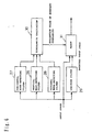
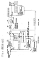
- Fig. 24 is a block diagram showing the structure of the image-encoding device and the decoding device based on this H.261, wherein reference numeral 70 represents an predicted image-forming means, 71 represents a motion vector-detecting means, 72 represents a differential device, 73 represents a waveform-encoding means, 74 represents a waveform-decoding means, 75 represents an adder, 76 represents a frame delay means, 77 represents a Haffmann encoder, 78 represents a Haffmann decoder, 79 represents a waveform-decoding means, 80 represents an adder, 81 represents a frame delay means and 82 represents an predicted image-forming means.
- reference numeral 70 represents an predicted image-forming means
- 71 represents a motion vector-detecting means
- 72 represents a differential device
- 73 represents a waveform-encoding means
- 74 represents a waveform-decoding means
- 75 represents an adder
- 76 represents a frame delay means
- 77 represents a Haffmann encoder
- the motion vector-detecting means 71 detects a motion vector having a minimum sum of the differential absolute value with the decoded image of the previous frame, with respect to the block composed of 16 x 16 pixels (referred to as a macro block) of the input image.
- the predicted image-forming means 70 forms an predicted image, by inputting this motion vector and the decoded image of the previous frame.
- the differential device 72 outputs the differential image of the input image and the predicted image (hereinafter referred to as "prediction error image' or 'residual difference image").
- the waveform-encoding means 73 subjects this differential image to the discrete cosine transform DCT with regard to blocks composed of 8 x 8 pixels, to transform the image to the DCT coefficient corresponding to the frequency, and the Haffmann encoder 77 subjects this to the variable-length encoding.
- the waveform-decoding means 75 has the same structure with that of the waveform-decoding means 79 on the decoding side, to perform the inverse discrete cosine transform (IDCT) and reconstruct the prediction error image.
- the adder 75 adds this to the present predicted image to form the image reconstructed on the decoding side. This image is delayed by the frame delay means 76 and used for the prediction of the next frame.
- DCT coefficient is decoded by the inverse Haffmann encoder 78, thereafter, respective blocks perform the same movements as those of blocks having the same name on the encoding side, thereby the image is reconstructed.
- the predicted image of the present frame is made as a motion-compensating image from the image of the previous frame by the block correlation method (hereinafter this processing is referred to as "motion compensation"), and the prediction error image of this motion compensation image and the present frame image is encoded.
- motion compensation the block correlation method
- the volume of the information to be transmitted is only for the motion vector, thereby the image can be transmitted with a small encoded volume.
- the dynamic image can be encoded with a smaller encoded volume compared to the case where the encoding within the frame is performed without utilizing the correlation between frames.
- H.261 is a specification of the image-encoding method and device recommended for the purpose of transmitting the image having a size of length and breadth of at least 144 x 176 pixels or so with the encoded volume of about 64 kilobits/sec.
- the DCT coefficient has to be quantized roughly.
- the mosquito noise caused in the vicinity of the edge because a strong edge cannot be expressed by the DCT coefficient, and the block noise generated in the block boundary due to the difference between the average luminance levels of DCT blocks are perceived as a visual disturbance.
- the accuracy against the motion of the motion compensation is performed by the unit of one pixel. And in the recent dynamic image-encoding technique, it is performed with the motion accuracy of 1/2 pixel.
- the motion of a substance takes an integer value of the pixel
- the predicted image ideally coincides with the input image without error.
- the input pixel value is predicted by the interpolation or extrapolation of the pixel value in the vicinity thereof, thereby the prediction error in an impulse form is generated in the vicinity of the edge, even if the motion prediction is correct. This is shown in Fig. 22. Referring to Fig.
- the morphology processing is a processing conducted for a shape of binary image or a planar shape of density of a multivalue image, and this is explained in detail in Literature 1, "Academic Press” (Henk J.A.M. Heijmans: Morphological Image Operators, Academic Press, Inc. 1994) and Literature 2, “IEEE Transaction on Pattern Analysis and Machine Intelligence” (R. M. Harallick, S. R. Sternberg, and X. Zhuang: Image Analysis Using Mathematical Morphology, IEEE Transaction on Pattern Analysis and Machine Intelligence, Vol. PAMMI-9, No. 4, pp. 532-550, July 1987).
- Binary image which is an image to be processed is assumed to be X, and a structuring element (a set of a two-dimensional position vector, domain) is assumed to be B. And one image constituting B is assumed to be expressed by a pixel vector b.
- Minkowski difference gives a domain (product set) common to the structuring elements whose all constituent elements are moved in translation by X, and on the contrary, Minkowski sum gives a union thereof.
- Erosion and Dilation are expressed by the following expression:
- f(x) luminance value
- F is a defined region
- g is a function of structuring elements (scalar value)
- G is the defined region thereof (domain), it is defined that:
- the input image is first predicted from different images, and subjected to the threshold processing and a region having a large residual difference is extracted as a pattern information.
- the pattern information is subjected to the dilation processing after the erosion processing of said morphology operation, that is, the opening processing, to.be deformed.
- the region in the form of impulse in the vicinity of the edge is eliminated.
- the prediction means predicts the input image from different images, and the threshold processing means outputs the region having a large residual difference as a pattern information.
- Said morphology means subjects this pattern information to an equivalent processing as said opening processing by the morphology means, and outputs a mask pattern in which the region in the form of impulse is eliminated.
- the waveform encoding means encodes based on this mask pattern, ignoring the region where it does not cause a large visual deterioration even if the residual difference encoding is not performed.
- 7 represents an image-encoding device
- 1 and 12 represent dividing means
- 2 represents a smoothing means
- 3 represents an extracting means
- 4 represents a contour-encoding means
- 5 represents a discrete cosine transform means
- 6 represents a waveform-encoding means
- 10 represents an image-decoding device
- 11 represents an input means
- 13 represents an identifying means
- 14 represents an decoding means
- 16 represents a code book
- 17 represents a selection means
- 18 represents a transmission means
- 26 represents a vertical edge-detecting filter
- 27 represents a horizontal edge-detecting filter
- 28 represents an oblique edge-detecting filter
- 29 represents a low-pass filter
- 30 represents a singularity-calculating section
- 31 represents a mixer.
- 101 and 102 represent layer image encoders
- 103 represents a multiplexer
- 104 represents a demultiplexer
- 105 and 106 represent layer image decoders
- 107 represents a layer image synthesizer
- 201 represents a deformation analyzer
- 202 represents a deformation synthesizer
- 203 and 204 represent differential devices
- 205 represents a prediction code encoder
- 206 represents a luminance plane error encoder
- 207 represents an ⁇ plane error encoder
- 208 represents a luminance plane error decoder
- 109 represents an ⁇ plane error decoder
- 210 represents a multiplexer
- 211 and 212 represent adders
- 313 and 214 represent frame delay devices
- 301 represents a demultiplexer
- 302 represents a luminance plane error decoder
- 303 represents an ⁇ plane error decoder
- 304 represents a prediction code decoder
- 305 represents a deformation synthesizer
- 48 and 64 represent predicted image-forming means
- 49 represents a motion vector-detecting means
- 50 represents a subtracter
- 51 represents a threshold processing means
- 52 represents a morphology operation means.
- 53 represents a smoothing filter
- 54 represents a mask processing means
- 55 represents a waveform coding means
- 56 and 61 represent a waveform decoding means
- 57 and 62 represent adders
- 58 and 63 represent frame delay means
- 59 represents a Haffmann encoder
- 60 represents a Haffnann decoder.
- Fig. 1 is a block diagram showing the structure of the image-encoding device and the image-decoding device of an embodiment which is helpful for the understanding of the present invention, and the structure will be described with reference to this drawing.
- the dividing means 1 inputs the image to be coded, and divides the input image into blocks comprising pixel numbers of 8 x 8.
- the smoothing means 2 is to transform ⁇ value 1 as a pixel value to 255 and ⁇ value 0 to 0 to subject the image to the smoothing processing, and to form a regional image having an intermediate value.
- the extracting means 3 is a means to extract a block where pixels having different ⁇ values in the same block are mingled, among respective blocks divided by the dividing means 1.
- the contour-encoding means 4 is a means to obtain a positional information for identifying the position on the original image of the block extracted by the extracting means 3, and to subject the positional information to the chain encoding.
- the discrete cosine transform means 5 is a means to obtain the DCT coefficient by conducting the discrete cosine transform (hereinafter referred to as DCT) for the pixel pattern in the block extracted by the extracting means 2, and the waveform-encoding means 6 is a means to perform variable-length encoding for the DCT coefficient obtained by the discrete cosine transform means 5.
- the image-encoding device 7 is composed of respective means described above.
- the input means 11 is to input the contour encoding data which is the output data from the contour encoding means of the image-encoding device 7, and the variable-length encoding data which is the output data from the waveform encoding means 6, and the dividing means 12 is to divide the image to be decoded into blocks comprising pixel numbers of 8 x 8 as in the dividing means 1.
- the identifying means 13 is to decode the contour encoding data input to the input means 11 among blocks divided by the dividing means 12, and as a result, to identify the block where pixels having different values are mingled
- the decoding means 14 is a means to decode the variable-length encoding data corresponding to the pixel pattern in the block identified by the identifying means 13.
- the image-decoding device 10 is composed of respective means of from the input means 11 to the decoding means 14 described above.
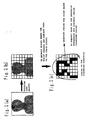
- Figs. 2 (a) to (c) are views illustrating the process of the encoding processing when a human image is embedded into the background image.
- Fig. 2 (a) shows an image to be coded
- Fig. 2 (b) shows the image divided into blocks
- Fig. 2 (c) shows blocks extracted as subjects to be chain-coded and waveform-coded (regions painted black in the drawing).
- the dividing means 1 obtains the image input (see Fig. 2 (a)), and divides the image into blocks comprising pixel numbers of 8 x 8 (see Fig. 2 (b)).
- ⁇ value 1 is transformed to 255 and ⁇ value 0 is transformed to 0 by the smoothing means 2 to subject the image to the smoothing processing. Thereby, a regional image having an intermediate value is constituted.
- blocks are divided into three types by the extracting means 3 as described below.
- blocks in which all ⁇ values within the block are composed of 255 are blocks in the inside region of the substance. And blocks in which ⁇ values of from 0 to 255 are mingled within the block are blocks in the boundary region of the substance. And, blocks in which all ⁇ values within the block are composed of 0 are blocks in the outside region of the substance.
- the extracting means 3 searches the regions where the ⁇ values of from 0 to 255 are mingled within the block toward inside in the clockwise direction in order to extract blocks where all the ⁇ values within the block are composed of 255, and extracts the applicable blocks.
- the contour encoding means subjects the block positions as the positional informations for identifying the positions of each block thus extracted, (x0, y0), (x1, y1),,,,, (xN-1, yN-1) to the curvature chain coding.
- blocks in the boundary region are subjected to the DCT (discrete cosine transform), and the DCT coefficient is subjected to the variable-length coding by the waveform coding means 6.
- DCT discrete cosine transform
- Figs. 2 (a) - (c) show a case where the order of processings is slightly different from the above description and a processing to extract predetermined blocks is conducted before the smoothing processing, however, it is a matter of course that predetermined blocks may be extracted after being subjected to the smoothing processing as described above (see Fig. 3).
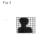
- Fig. 3 is a view showing the smoothed image in which the boundary portions of the substance have an intermediate value of [0, 1], that is, ⁇ values of from 0 to 255.
- the action of the decoding processing is inverse of the action described above.
- the data output from the image-encoding device 7 side is input to the input means 11, and the dividing means 12 divides the image to be decoded into blocks having pixel numbers of 8 x 8.
- the identifying means 13 decodes the chain coding data obtained by the input means 11. Thereby, the identifying means 13 classifies blocks into three types, that is, blocks which are encircled by the clockwise rotation are blocks in the inside region, blocks which are not encircled thereby are blocks in the outside region, and blocks in the boundary region, to identify the blocks in the boundary region.
- the decoding means 14 decodes the variable-length coding data for the blocks in the boundary region, inversely transforms the DCT coefficient, and outputs the image data shown in Fig. 3.
- the present embodiment relates to the image-encoding device which transmits and accumulates the input image, especially the regional image showing the occupancy region of the projective image of a substance with a little coding volume, by the coding method which combines the chain coding and the waveform coding.
- the image is divided into blocks to form an image with a low resolution equivalently which makes blocks comprising different pixel values the boundary, and blocks in this boundary are subjected to the contour coding.
- the pixel pattern within the block is subjected to the waveform coding. Therefore, when it is assumed that waveform coding within the block is a non-reversible coding, it exerts the effect that images having no visual deterioration can be coded with a few contour codes. Furthermore, such an effect is particularly successful when the image is animation or the like.
- the space resolution is adequate in the range that there is no visual deterioration, and on the contrary, in the vicinity of the regional boundary, the coding devices and decoding devices having excellent amplitude resolution compared to the coding, and the coding methods and decoding methods using the same are quite effective.
- Fig. 4 is a block diagram showing the structure of the image-coding device and the image-decoding device, and the structure of the embodiment will be described with reference to Fig. 4.
- the dividing means 15 inputs the image to be coded, divides the input image into regions comprising pixel numbers of 4 x 4, and outputs the pixel pattern within the region obtained by the division.
- the smoothing means 19 as the quantization patterning means of the present invention is a means to smooth and output the data output from the dividing means 15.
- the smoothing processing here is a processing to transform respective pixel values comprising two values of ⁇ 0, 1 ⁇ of the pixel pattern in the image to be coded to the intermediate value of from 0 to 255 in order to quantize more finely. Therefore, this smoothing means 19 forms a regional image having an intermediate value of [0, 255] based on the image comprising binary pixel values of ⁇ 0, 1 ⁇ as a subject to be coded.
- the code book 16 is formed to have quantized patterns selected as representative patterns, from quantized patterns in which the pixel values are more finely quantized compared to respective pixel values of the pixel pattern within the region obtained by dividing each image for every region by utilizing plural kinds of images, by LBG algorithm described below.
- the selection means 17 is a means to select the quantized pattern which most approximately represents the pixel pattern in the image, among the code books 16 formed as described above, and to output the index informations corresponding to the selected quantized pattern
- the transmission means 18 is a means to transmit the index information output from the selection means 17.
- the image-encoding device 20 is composed of the above-mentioned respective means.
- the code book 16 when in the above-mentioned image-encoding device 20, the code book 16 is utilized and the index information corresponding to the quantized pattern selected as the one expressing most approximately the pixel pattern in the image to be coded is transmitted, the input means 21 obtains and outputs the transmitted index information.
- the same code book 22 as the above-mentioned code book 16 is also provided.
- the reading means 23 is a means to examine the contents of the code book 22 from the index information output from the input means 21 and to read out the corresponding quantized pattern
- the decoding means 24 is a means to use the quantized pattern read out by the reading means 23 to decode the image to be decoded as the image whose pixel value is quantized more finely compared to the image to be coded.
- the image-decoding means 25 is composed of respective means of from the input means 21 to the decoding means 24 described above.
- Fig. 5 is a view simply expressing the change of the image in an image view in the state that the image is subjected in sequence to the processings such as smoothing, vector quantization and the like, when a human image is embedded into the background image.
- each image is divided into blocks comprising pixel numbers of 4 x 4 by using plural kinds of images. Then, ⁇ value 1 is transformed to 255, and ⁇ value 0 is transformed to 0, and the image is subjected to the smoothing processing. Thereby, the regional image having an intermediate value is constituted.
- the code book is designed by the LBG algorithm (Y. Linde, A. Buzo and R.B. Gray : "An Algorithm for Vector Quantizer Design", IEEE Transaction on Communication. Vol. COM-28, No. 8, pp. 957-911, (Aug. 1988).
- the code book is designed for the regional image having an intermediate value, not the value of 0/1.
- the size of the code book is made to be 256 selected as a representative pattern. This is 1/256 compared to the 0/1 pattern numbers (the 16th power of 2) which the block comprising the pixel numbers of 4 x 4 has.
- the dividing means 15 divides the image to be coded into blocks comprising pixel numbers of 4 x 4, and the smoothing means 19 transforms ⁇ value 1 to 255 and ⁇ value 0 to 0 to subject the image to the smoothing processing. Thereby, the regional image having an intermediate value is composed.
- the selecting means 17 examines the code book 16, compares with the pixel pattern divided into blocks subjected to the smoothing processing, and searches a pattern having the smallest squared error sum, and as a result, outputs the index information corresponding to the pattern expressed most approximately to the transmission means 18, thus the index information is transmitted from the transmission means 18 to the image-decoding device 25.
- the input means 21 obtains said index information
- the reading means 23 reads out the quantized pattern corresponding to the index information obtained by the input means 21 from the code book 22
- the decoding means 24 uses the read-out quantized pattern to decode the image to be decoded as an image whose pixel value is more finely quantized compared to the original image to be coded.
- Fig. 6 is a block diagram showing the structure of the smoothing means which is a characteristic part of the image encoding device of the present embodiment, and the structure of the present embodiment will be described with reference to Fig. 6. In addition, description of the same portions as those of Fig. 4 will be omitted.
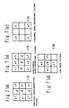
- a vertical edge-detecting filter 26, a horizontal edge-detecting filter 27, an diagonal edge-detecting filter 28, and a low-pass filter 29 are filters having characteristics shown in Figs. 7 (a), (b), (c) and (d), respectively, and any filter inputs the original signal of the input image and outputs a predetermined response.
- a singularity-calculating section 30 inputs response V from the vertical edge-detecting filter 26, response H from the horizontal edge-detecting filter 27, and response D from the diagonal edge-detecting filter 28 to calculate C as the complexity of the contour by Equation 1 described below, and outputs the value of C as the calculation result.
- Figs. 7 (a) - (d) are diagrams showing the characteristics of various filters.
- the vertical edge-detecting filter 26, the horizontal edge-detecting filter 27, and the diagonal edge-detecting filter 28 which have obtained the signal of the input image output V, H and D to the singularity-calculating section 30 as responses corresponding to respective filter characteristics.
- * means multiplication
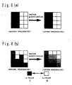
- Figs. 8 (a) and (b) are views illustrating examples of the smoothing processing of the present embodiment, and Fig. 8 (a) shows the smoothing processing with respect to the linear edge, and Fig. 8(b) shows the smoothing processing with respect to the edge having a complex contour.
- judgment of complexity of the contour can be performed by dispersion of the whole curvature functions of the contour. Furthermore, in the more general case containing concentration value, it can be evaluated by Hadamard's transformation coefficient, Fourier transformation coefficient, DCT coefficient and the like.
- the image processing device and the method thereof are utilized as the smoothing means 19 which is the preprocessing of the image-encoding device 20 has been described, but it is not restricted to that case, and for example, they are utilized as the means of the preprocessing of the image-encoding device 7, or the post-processing of the image-decoding device 10, or the post-processing of the image-decoding device 25.
- the image is composed of the length and the breadth 288x 352 pixels in order to easily understand the action of the device, and that the layer does not loose the generality and is composed of only two portions, background and foreground.
- the block which performs correlation operation for detecting the motion vector is composed of the length 16 pixels x the breadth 16 pixels.
- Fig. 10 is a view showing the structural example
- Fig. 11 is a view showing the structural example of the invention.
- Fig. 9 is a structural view of the layer coding system illustrating the action of the image-encoding device and the image-decoding device.
- the layer image is composed of two frames: luminance and opacity. These are referred to, respectively, as the luminance plane and the a-plane.
- Equation 2 (x, y) represents the horizontal/vertical position, gf and gb represent a luminance value [0, 255] of the foreground and the background, respectively, and a represents the opacity [0, 1] of the foreground. g is a synthesized luminance value.
- all the opacity of the background is composed of 1.
- the layer image encoders 101 and 102 encodes respective dynamic images of the luminance plane and the ⁇ plane in the foreground and the background, and the bit stream multiplexed by the multiplexer 103 are sent to the decoding device.
- the data of respective layer images are divided by the demultiplexer 104, and the layer images are reconstructed by the layer image decoders 105 and 106.
- the reconstructed layer images are synthesized by the layer image synthesizer 107.
- Fig. 10 is a structural view of the layer image encoders 101 and 102 of Fig.9.
- 201 represents a deformation analyzer
- 202 represents a deformation synthesizer
- 203 and 204 represent differential devices
- 205 represents a prediction code encoder
- 206 represents a luminance plane error encoder
- 207 represents an a plane error encoder
- 208 represents a luminance error decoder
- 209 represents an ⁇ plane error decoder
- 210 represents a multiplexer
- 211 and 212 represent adders
- 213 and 214 represent frame delay devices.
- the deformation analyzer 201 determines which position of the luminance plane and the ⁇ plane which are the decoding result of the previous frame corresponds to to each other with respect to respective positions of the luminance plane and the ⁇ plane currently input.
- the correspondence information of this position is encoded as the affine transformation parameter and the block parallel movement component by the prediction code encoder 205.
- the deformation synthesizer 202 receives this correspondence information, and deforms the luminance plane and ⁇ plane which are the decoded results of the previous frame, to make them the differential signal by the differential devices 203 and 204. When it is restricted to the luminance plane, this generally corresponds to a processing called as ''motion compensation" in the image-encoding devices and the like described in CCITT Recommendation H.
- Fig 14 shows the structure of the deformation synthesizer 202 of Fig. 10, and in the drawing, 601 represents a luminance image memory, 602 represents an a image memory, 603 represents a demultiplexer, 604 and 605 represent affine transformation sections, 606 and 607 represent affine transformation image memories, 608 and 609 represent image block-deforming section.
- the correspondence information (deformation parameter) is composed of the affine transformation parameter (see Equation 1) and translational movement component (see Fig 20) with respect to blocks divided into the length and the breadth 18 x 22.
- the steps of the motion compensation are as follows:
- the deformation analyzer 201 of Fig. 10 has to extract the affine transformation parameter and the block movement component to perform this processing.
- Fig. 12 is a structural view of the deformation analyzer 201 of Fig. 10. The action of the deformation analyzer 201 will be described by using Fig. 12.
- the structure of the deformation analyser 201 shown in Fig. 12 is a structural example of the motion vector-detecting device.
- 401 and 402 represent luminance image memories
- 403 and 404 represent a-image memories
- 405 and 406 represent luminance/ ⁇ superposing sections
- 408 represents an affine transformation image memory
- 409 represents an affine transformation image memory
- 410 represents a block correlation operation section
- 411 represents a multiplexer.
- the luminance image memory 401 and the a - image memory 403 buffer the result of the previous frame as the reference image.
- the luminance image memory 402 and the a-image memory 404 hold the image of the current input frame which is the image to be encoded.
- the luminance/a superposing sections 405 and 406 perform the processing shown in Equation 3 to form one luminance image.
- Equation 3 h(x, y) represents a synthesized luminance image, g represents a luminance value [0, 255] of the luminance plane, and a represents ⁇ value [0, 1] of ⁇ plane, with respect to the horizontal/vertical position (x, y) of the pixel.
- Equation 3 the luminance value is superposed in the opaque region, and a proper negative value (-100) is superposed in the transparent region by the value of a. Thereby, the luminance image superposed by the information of the opacity is formed.
- Equation 5 the correlation operations provided by Equation 5 and Equation 6 are performed for the image to which the luminance and the ⁇ value are superposed.
- Equation 5 ht-1 represents the superposed pixel value of the previous frame (Fig. 12, reference image), and ht represents the superposed pixel value of the current frame (Fig. 12, object image).
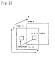
- R represents the region of 16 x 16 pixels, and (u, v) represents deviation to the corresponding block region, as shown in Fig. 20.
- the smallest deviation of SAD is determined as a motion vector.
- the block correlation section 410 carries out this operation relating to the affine transformed reference superposed image and the object superposed image.
- the output of the a-image memory 404 is input to the block correlation section 410.
- the block correlation section 410 outputs the smallest deviation (p, q) relating to 18 x 22 blocks as the motion vector.
- the affine transformation section 407 and the affine transformation image memory 409 perform the same actions as those of the block of the same name described in Fig. 14.
- Fig. 13 is a structural view of the affine transformation coefficient operational section 408, and shows the structural example of the motion vector-detecting device.
- 501 represents a block correlation operational section
- 502 represents a SAD surface approximation section
- 503 represents an error function parameter-storing memory
- 504 represents an affine transformation parameter operation section.
- the action of the block correlation operational section 501 is roughly the same as that of the block correlation section 410 of Fig. 12.
- the different point is that the block correlation operational section 501 outputs the deviation (p, q) which becomes the smallest with respect to 18 x 22 blocks, and in addition to that, the SAD smallest value of the position and the SAD value in the vicinity of 8.
- Equation 7 represents transpose of the matrix.
- S (E(p-1, q-1), E(p-1, q), E(p-1, q+1), E(p,q-1), E(p,q), E(p,q+1), E(p+1,q-1), E(p+1,q), E(p+1,q+1)) t
- the SAD phase approximation section 502 receives this to carry out the operations of from Equation 8 to Equation 13.
- the operation results are stored in the error function parameter storing memory 503.
- Operations of from Equation 8 to Equation 13 correspond to perform the quadratic Taylor development in the vicinity of the smallest deviation (p, q), considering the SAD value as the function of the deviation (u, v). If the position of the block of the length and the breadth 18 x 22 is expressed as i and j, respective quadratic error functions can be expressed by Equation 14, except for the transparent region.
- Equation 17 since the motion vector is described by the affine transformation parameter, as the necessary condition to make the sum total of respective SAD error functions minimum by the variational principle, as shown in Equation 17, the Euler's equation can be derived in which the partial differential of the affine transformation parameter a must be zero vector. This can be expressed by the matrix of Equation 18.
- the affine parameter operational section 504 first determines Equation 19 (6 x 6 matrix) and Equation 20 (6 x 1 matrix), and calculates the affine transformation parameter by Equation 21.
- Equation 19 (xj, yi) represents the central position of the blocks i and j.
- the motion vector can be determined from both informations by conducting the correlation operation with the image superposed with the luminance and ⁇ . If the absolute value of the negative value (-100) of the tranparent region determined by Equation 3, the motion vector in which the information of contour of the opaque region is further stressed can be obtained. Particularly, it is effective when there are no clues such as edges or patterns effective for predicting the motion within said region.
- the affine transformation coefficient operational section 408 determines the affine transformation parameter by performing the quadratic function approximation, not by the local correlation operation. In the local correlation operation, there are many cases that the motion vector has the freedom in the direction of the contour tangent in the periphery of monotonous contour.
- the quadratic function approximation in which the deviation of SAD correlation is a variable has an advantage in that it can easily derive the undetermined parameters, since the Euler's equation represented by Equation 17 becomes linear expression with respect to the undetermined parameters. This is true in common even in the case where more general polynomial is used.
- the deformation analyzer 201 and the deformation synthesizer of the layer image encoders 101 and 102 have been heretofore described. Simultaneously, the structural example of the motion vector-detecting device has been shown. Hereinafter, remaining blocks in Fig. 10 will be described.
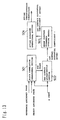
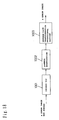
- Fig. 15 is a structural view of the luminance plane error encoder, and 701 represents a DCT operational section, 702 represents a quantization section, and 703 represents a variable-length coding section 1.
- Fig. 16 is a structural view of the ⁇ plane error encoder, and 801 represents a Haar transformation operational section, 802 represents a quantization section, and 803 represents a variable-length coding section 2.
- DCT operational section 701 performs the discrete cosine transform at the blocks of 8 x 8 pixels, and the transformed DCT coefficient is quantized by the quantization section 702, and the cosine transform coefficient is scanned by the variable-length coding section 703 to be subjected to the two-dimensional Haffmann coding in combination with the zero coefficient length and the quantization coefficient.
- This processing is roughly the same with the technology disclosed in CCITT Recommendation H.261, therefore, detailed description will be omitted.
- Haar transformation is used in the blocks of 8 x 8 pixels, instead of the discrete cosine transform.
- the Haar transformation is realized by performing the one-dimensional Haar transformation in which the column vector of 8 x 1 is multiplied from the right of the Equation 25 with respect to the pixel blocks of 8 x 8 lengthwise and crosswise.
- the output of the luminance plane error encoder 206 and the ⁇ plane error encoder 207 heretofore described is multiplexed by the multiplexer 210 and output.
- the output described above is input to the luminance plane error decoder 208 and the ⁇ plane error decoder 209 in order to form the predicting image of the next frame.
- Each decoder has the structure shown in Fig. 17 and Fig. 18.
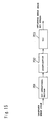
- Fig. 17 is a structural view of the luminance plane error decoder, and 901 represents a variable-length decoding section, 902 represents an inverse-quantization section, 903 represents an inverse DCT operational section.
- Fig. 18 is a structural view of the a plane error decoder, and 1001 represents a variable-length decoding section, 1002 represents an inverse-quantization section, 1003 represents an inverse Haar transformation operational section.
- the variable-length decoding section 901 subjects the combination of the zero coefficient length and the quantization coefficient to Haffmann decoding and returns it to the cosine transform coefficient.
- the inverse-quantization section 902 replaces the quantization index with the representative value, and lastly, the image of 8 x 8 pixel blocks is reproduced by the inverse DCT operational section 903.
- This processing is roughly the same with the technology disclosed in CCITT Recommendation H.261 as in the luminance plane error encoder 206, therefore, detailed description will be omitted.
- the inverse Haar transformation operational section 906 is realized by taking out the column vector of 8 x 1 lengthwise and crosswise with respect to the Haar coefficient of 8 x 8, and multiplying the matrix shown in Equation 26 from the left.
- the action of the variable-length decoding section 1001 and the inverse-quantization section 1002 is different only in the contents of the table from said block of the luminance plane decoder 209, corresponding to the ⁇ plane error encoder 207, therefore the detailed description thereof will be omitted.
- Fig. 12 is a structural view of the layer image decoders 105 and 106 corresponding to the structural example of the image decoding device.
- 301 represents a demultiplexer
- 302 represents a luminance plane error decoder
- 303 represents an ⁇ plane error decoder
- 304 represents a prediction code decoder
- 305 represents a deformation synthesizer
- 306 and 307 represent adders
- 308 and 309 represent frame delay devices.
- the luminance plane error decoder 302, the a-plane error decoder 303 and the deformation synthesizer 305 perform the same action with that of the luminance plane error decoder 208, the ⁇ plane error decoder 209 and the deformation synthesizer 202 of Fig. 10, respectively.
- the first embodiment in which the structures of the layer encoders 101 and 102 and layer decoders 105 and 106 constituting the layer encoding of Fig. 9 are as shown in Fig. 10 and Fig. 11 has been described.
- the present embodiment has a characteristic in that the template is up-dated sequentially as encoding between frames. The difference of the opacity among templates is subjected to the transformation encoding as the waveform information having gray-scales.
- the dynamic image of the semitransparent substance such as a frosted glass and the like can be handled, being different from the second embodiment described below. Since the image is stratified, such cases where the foreground and the background can be described only by the affine transformation parameter are increased.
- the affine transformation parameter since only the affine transformation parameter is transmitted, and it is not required to encode the block movement component, other luminance error images and ⁇ plane error images, the encoding efficiency is greatly improved. Furthermore, when the substance is deformed and cannot be described by the affine transformation parameter, the template is up-dated by the block movement component, other luminance error images and ⁇ plane error images. thereby the image is not deteriorated largely.
- the operations of Equations 19 - 21 carried out by the affine parameter operational section 504 are not required to be conducted in the whole image.
- the affine transformation parameter matching to the movement of a plurality of blocks, not the total block assembly divided into 18 x 22, can be predicted.
- encoding of the block movement component, other luminance error images and ⁇ plane error images for the correction of templates is conducted locally.
- the calculation of the block correlation is performed by SAD, but it is possible to use other evaluation measures such as squared error sum (SSD) and correlation coefficient.
Description
- The present invention rotates to image-decoding methods available for decoding images, especially regional images showing the occupancy region of a projective image of a substance, and devices thereof.
- Conventionally, when images are synthesised by computer graphics and the like, informations relating to the opacity(transparency) of a substance referred to as 'a value", other than the luminance of the substance are required.
- The α value is determined for every pixel, and the α value of 1 means non-opacity, and the a value of 0 means complete opacity. Namely, when an image of a certain substance is embedded in the background, an image having the α value is necessary. Hereinafter, the images having such a values are referred to as "α plane". Incidentally, the α value has an intermediate value of [0, 1] in the case of substances such as clouds, frosted glass and the like, but in many substances, it tends to have two values of {0, 1}.
- Encoding of the α plane may be conducted as direct enumeration of the pixel value, however, when the α plane is composed of two values of {0, 1}, binary image-encoding techniques MH, MR, MMR encoding which are the international standard by CCITT and used conventionally for facsimile and the like may be used. These are named generally as "run-length coding'.
- In the run-length coding, pixel number of horizontally or horizontally/vertically continuous 0 and 1 is entropy-coded to perform coding efficiently.
- Furthermore, taking notice of the contour of substance boundary, positional informations of each pixel constituting the contour may be coded. In the present specification, encoding of the contour of substance boundary is hereinafter referred to as contour encoding.
- As typical contour encoding, there can be mentioned a chain enconding (described in H. Freeman: "Computer Processing of line drawing data", Computing Surveys, vol. 6, no. 1, pp. 57-96, (1974)).
- In an image having a simple contour of the substance boundary, the value of α plane can be encoded highly efficiently by chain-coding the group of each pixel constituting the contour of the region having the α value of 1.
- Considering the visual characteristics affected by the decoded result of α plane, there has been a defect in that in the above-mentioned run-length coding method and the chain coding method and the devices thereof, since encoding/decoding are carried out for every pixel, patterns of {0, 1} are coded/decoded accurately more than required from the view point of human visual characteristics, though it is not necessarily required to decode the pattern of {0, 1} accurately, thereby a large coded volume becomes necessary.
- Namely, concretely explained, in a general image synthesizing, a processing to mix the image with the color value of the background image referred to as "anti-aliasing" is performed in the vicinity of boundary of the image to be synthesized. This is equal to smooth the a value in the vicinity of the substance boundary, considering the α value to be gray-scales of [0, 1] equivalently. Namely, in the image such as α plane, the space resolution is not so required. Instead, the amplitude resolution becomes necessary in the vicinity of the substance boundary.
- In the conventional run-length coding and chain coding, there has been a problem in that since they are reversible coding, the space resolution is more than necessary from the view point of visual characteristics, thereby a large coded volume become necessary.
- J. Wang and E. Adelson describe in ''Representing Moving Images with Layers" in IEEE Transactions on Image Processing, September 1994, on pages 625 to 637 to represent moving images by overlapping layers. Each layer contains an intensity map, an alpha map and a velocity map. The intensity map defines an intensity value at each image point of a layer, the alpha map indicates the transparency at each point and the velocity map describes how the map should be warped over time. The layered composition of an image sequence may be used for image compression by encoding the data of the maps separately. Wang et al. describe to use a JPEG encoder for coding the intensity data. The alpha data are encoded by using a chain code. The motion parameters are sent without compression.
- Musmann et al. describe in "Object-Oriented Analysis-Synthesis Coding Of Moving Images" in Signal Processing: Image Communication, vol. 1, January 1989 an object-oriented coder. Each image object of an image to be encoded is described by three sets of parameters which define motion, shape and color information of the object to be encoded, respectively. The motion parameter contains a frame-to-frame displacement of the object The shape parameter describes the shape of the object by bi-level image data and the color parameter corresponds to the luminance and color information of each picture element of the object. Motion parameters are encoded using a DPCM technique. The shape parameters of an object are encoded, depending on the size of the object, by a contour coding algorithm in combination with predictive coding. Color information is compressed based on a hybrid coding scheme combining motion compensation prediction with intra-frame coding.
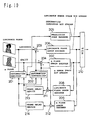
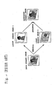
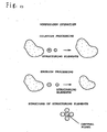
- Furthermore, there has been conventionally proposed a method to encode dynamic images by resolving the dynamic image into layer image, as shown in Fig. 21, in order to efficiently perform opacity and recording of the dynamic image, by J. Wang and E. Adelson.
- Edward H. Adelson describes in "Layered representation for image coding", technical report 181, MIT Media lab, 1991, the use of multiple layers for encoding image sequences. Each layer comprises a number of maps, in particular an intensity map, a delta map, a velocity map and an attenuation map. Each of these maps used in the layers can be compressed using standard image coding techniques such as transform coding or subband coding.
- According to the literature "Layered Representation for Image Sequence Coding" by J. Wang and E. Adelson, Proc. IEEE Int. Conf. Acoustic Speech Signal Processing '93, pp. V221-V224, 1993, and "Layered Representation for Motion Analysis" by J. Wang and E. Adelson, Proc. Computer Vision and Pattern Recognition, pp. 361-366, 1993, in which this method is disclosed, the image processings of from (1) to (3) described below are performed:
- (1) A region described by the same motion parameter (in the conventional case, affine transformation parameter) is extracted from the dynamic images.
- (2) A layer image is formed by superposing the same motion region. Each layer image is expressed by the opacity and luminance for every pixel showing the occupancy of the superposed region.
- (3) The upper and lower relations in the eyes' direction between layer images are examined and sequenced.
-
- Here, the affine transformation parameter means the coefficient of a0 - a5 shown in Expression 1, when the horizontal/vertical position in the image is assumed to be (x, y), and the horizontal/vertical component of the motion vector is assumed to be (u, v).
- It is known that the motion of the projective image of a rigid body located with a sufficient distance from a camera can be approximated by the affine transformation parameter. They utilize this to synthesize dynamic images of from several tens to several hundreds of frames, while transforming several kinds of layer images composed of one frame by the affine transformation. The informations required for transmitting and recording this dynamic image are only the image which is the base of deformation relating to each layer image (hereinafter referred to as ''template''), the affine transformation parameter, and the upper and lower relations of each layer image, therefore, recording and opacity of the dynamic image can be performed at a very high coding efficiency. In addition, the template is expressed by the opacity and the luminance for every pixel showing the occupancy of the region, for the image synthesis.
- In the dynamic image expression by J. Wang and E. Adelson, the projective image deals with only the motion of a rigid body which can be described by the affine transformation. Therefore, their dynamic image expression cannot cope with the case where the motion of the projective image cannot be described by the affine transformation. For example, when a person shown in Fig. 31 conducts a motion of non-rigid body, if the camera-substance distance is small and the nonlinear item of perspective transformation cannot be ignored, it cannot be applied thereto. Moreover, their technique to determine the motion of projective image as the affine transformation parameter is composed of processings of two stages described below:
- 1. To determine a local motion vector at respective positions on the screen by a method based on the relational expression of space-time gradient of the luminance that the time change of the luminance can be approximated by the space luminance gradient and the inner product of the motion vector (B. Lucas and T. Kanade: "An Iterative Image Registration Technique with Anaplication to Stereo Vision", Proc. Image Understanding Workshop, pp. 121-130, April 1981).
- 2. To determine the affine transformation parameter by clustering the obtained motion vector.
-
- In the above-mentioned technique, however, it cannot be applied when there is a big motion in the dynamic image such that the relational expression of the time-space gradient of the luminance cannot be realized. Furthermore, in the two-staged method to predict the affine transformation parameter from the obtained motion vector, there is caused a large prediction error when the motion vector which is the base of the parameter prediction is wrong. The motion vector is indefinite, in the region where there is no luminance change, or in the region composed of one-directional luminance change even if there is a luminance change. In the above-mentioned two-staged prediction technique, a special processing is required for the motion vector in these uncertain regions. Collectively, the following problems 1 and 2 are not dissolved.
- Problem 1 : Efficient encoding of images (template) having luminance and opacity having irregular deformation
- Problem 2 : Strong prediction of the affine transformation parameter
-
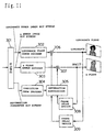
- Furthermore, in the conventional image-encoding methods and the devices thereof, for example, there is a method or a device described in CCITT Recommendation H.261. Fig. 24 is a block diagram showing the structure of the image-encoding device and the decoding device based on this H.261, wherein reference numeral 70 represents an predicted image-forming means, 71 represents a motion vector-detecting means, 72 represents a differential device, 73 represents a waveform-encoding means, 74 represents a waveform-decoding means, 75 represents an adder, 76 represents a frame delay means, 77 represents a Haffmann encoder, 78 represents a Haffmann decoder, 79 represents a waveform-decoding means, 80 represents an adder, 81 represents a frame delay means and 82 represents an predicted image-forming means.
- The image-encoding device and image-decoding device constituted as described above will now be described. First, the motion vector-detecting means 71 detects a motion vector having a minimum sum of the differential absolute value with the decoded image of the previous frame, with respect to the block composed of 16 x 16 pixels (referred to as a macro block) of the input image. The predicted image-forming means 70 forms an predicted image, by inputting this motion vector and the decoded image of the previous frame. The differential device 72 outputs the differential image of the input image and the predicted image (hereinafter referred to as "prediction error image' or 'residual difference image"). The waveform-encoding means 73 subjects this differential image to the discrete cosine transform DCT with regard to blocks composed of 8 x 8 pixels, to transform the image to the DCT coefficient corresponding to the frequency, and the Haffmann encoder 77 subjects this to the variable-length encoding. In order to make the predicted images formed on the encoding side and on the decoding side identical, the waveform-decoding means 75 has the same structure with that of the waveform-decoding means 79 on the decoding side, to perform the inverse discrete cosine transform (IDCT) and reconstruct the prediction error image. The adder 75 adds this to the present predicted image to form the image reconstructed on the decoding side. This image is delayed by the frame delay means 76 and used for the prediction of the next frame. On the decoding side, DCT coefficient is decoded by the inverse Haffmann encoder 78, thereafter, respective blocks perform the same movements as those of blocks having the same name on the encoding side, thereby the image is reconstructed.
- As described above, in the encoding mode between frames of the encoding device based on H.261, when the current frame image is encoded, the predicted image of the present frame is made as a motion-compensating image from the image of the previous frame by the block correlation method (hereinafter this processing is referred to as "motion compensation"), and the prediction error image of this motion compensation image and the present frame image is encoded. In this encoding device, when the motion-compensating image coincides with the previous frame without error, the volume of the information to be transmitted is only for the motion vector, thereby the image can be transmitted with a small encoded volume. Moreover, even if there is any movement in the dynamic image, when it is a simple movement or a local movement, the difference between the predicted image and the input image becomes small, thereby the dynamic image can be encoded with a smaller encoded volume compared to the case where the encoding within the frame is performed without utilizing the correlation between frames.
- By the way, H.261 is a specification of the image-encoding method and device recommended for the purpose of transmitting the image having a size of length and breadth of at least 144 x 176 pixels or so with the encoded volume of about 64 kilobits/sec. When the image having the same size is tried to encode at an encoding speed of about 20 kilobits/sec., the DCT coefficient has to be quantized roughly. Thereby, the mosquito noise caused in the vicinity of the edge because a strong edge cannot be expressed by the DCT coefficient, and the block noise generated in the block boundary due to the difference between the average luminance levels of DCT blocks are perceived as a visual disturbance.
- In H.261, the accuracy against the motion of the motion compensation is performed by the unit of one pixel. And in the recent dynamic image-encoding technique, it is performed with the motion accuracy of 1/2 pixel. When the motion of a substance takes an integer value of the pixel, the predicted image ideally coincides with the input image without error. Actually, however, it is not general that the motion takes the integer value of the pixel, and even if the accuracy of motion is increased (for example, to 1/2 pixel accuracy or 1/4 pixel accuracy), the input pixel value is predicted by the interpolation or extrapolation of the pixel value in the vicinity thereof, thereby the prediction error in an impulse form is generated in the vicinity of the edge, even if the motion prediction is correct. This is shown in Fig. 22. Referring to Fig. 22 (a), the input image moves horizontally toward the right while being deformed. Referring to Fig. 22 (b), the predicted image is square, and the position of "B" on the left edge is wrongly predicted due to the deformation. On the contrary, the portion "A" on the right edge coincides roughly.
- In the portion "A", however, though a visually appropriate predicted image is formed by the motion compensation, there is caused a prediction error which is subjected to the residual difference encoding, which becomes the factor to make the whole encoded volume large. Here in the drawing, (g), (h) and (i) express the luminance level cutting the input image, the predicted image and the residual difference image by A-B. This problem cannot be dissolved even if the waveform encoding means 73 is replaced by other transformation.encoding means such as a sub-band coding. Finally, selection of a portion where even if it is not a portion to be actually subjected to the residual difference encoding, it does not cause visual deterioration becomes a problem. This is not limited to H.261, but is a common problem for the methods and devices to encode the residual difference image by forming predicted image based on a certain image. In the example of Fig. 22, the portion 'B' obviously requires the residual difference encoding, but in the portion "A", the residual difference encoding is not required under a limited encoding speed.
- It is the object of the present invention to provide an improved decoding device. This is achieved by an image predictive decoding device with the features of claim 1.
- First, the morphology processing comprising a processing of dilation after erosion will be described. The morphology processing is a processing conducted for a shape of binary image or a planar shape of density of a multivalue image, and this is explained in detail in Literature 1, "Academic Press" (Henk J.A.M. Heijmans: Morphological Image Operators, Academic Press, Inc. 1994) and Literature 2, "IEEE Transaction on Pattern Analysis and Machine Intelligence" (R. M. Harallick, S. R. Sternberg, and X. Zhuang: Image Analysis Using Mathematical Morphology, IEEE Transaction on Pattern Analysis and Machine Intelligence, Vol. PAMMI-9, No. 4, pp. 532-550, July 1987). Here, the action of the present invention will be described with reference to the definition described in Literature 3, Hua-Rong JIN and Idefumi KOBATAKE: "Extraction of Microcalcifications on Mammogram Using Morphological Filter with Multiple Structuring Elements", IEICE Transaction, D2, Vol. J75-D-II, No. 7, pp. 1170-1176, 1992-7.
- Binary image which is an image to be processed is assumed to be X, and a structuring element (a set of a two-dimensional position vector, domain) is assumed to be B. And one image constituting B is assumed to be expressed by a pixel vector b. At this time, B' (here, ' is used for a convenience sake) is referred to as "symmetry of B", and the following expression is realized:
- Namely, Minkowski difference gives a domain (product set) common to the structuring elements whose all constituent elements are moved in translation by X, and on the contrary, Minkowski sum gives a union thereof. Based on these basic operation, Erosion and Dilation are expressed by the following expression:
- Erosion:
- Dilation:
- Opening:
- Closing:
-
- When it is assumed that f(x) is luminance value, F is a defined region, g is a function of structuring elements (scalar value), and G is the defined region thereof (domain), it is defined that:
- Erosion:

- Dilation:

- Opening:
- Closing:
-
- In the image-encoding method of the present invention, the input image is first predicted from different images, and subjected to the threshold processing and a region having a large residual difference is extracted as a pattern information. Thereafter, the pattern information is subjected to the dilation processing after the erosion processing of said morphology operation, that is, the opening processing, to.be deformed. Thereby, in the conventional example shown in Fig. 22, as shown in (e) and (k) as the morphology operation results, the region in the form of impulse in the vicinity of the edge is eliminated. By using this as a mask pattern to encode the residual difference image, high efficient encoding can be performed, ignoring a region where the residual difference encoding is not required. Similarly in the image encoding device of the present invention, the prediction means predicts the input image from different images, and the threshold processing means outputs the region having a large residual difference as a pattern information. Said morphology means subjects this pattern information to an equivalent processing as said opening processing by the morphology means, and outputs a mask pattern in which the region in the form of impulse is eliminated. The waveform encoding means encodes based on this mask pattern, ignoring the region where it does not cause a large visual deterioration even if the residual difference encoding is not performed.
- Fig. 1 is a block diagram showing the structure of the image-encoding device and the image-decoding device.
- Fig. 2 (a) is a view showing the image to be encoded of said embodiment;
- Fig. 2 (b) is a view showing the image divided into blocks of said embodiment;
- Fig. 2 (c) is a view showing a block extracted as a subject to be chain-encoded and waveform-encoded of said embodiment.
- Fig. 3 is a view representing the smoothed image of said embodiment in which the boundary portion of a substance has an intermediate value of [0, 1], that is, a value of from 0 to 255.
- Fig. 4 is a block diagram showing the structure of the image-encoding device and the image-decoding device of other embodiment.
- Fig. 5 is an image view showing the change of image in the state that the image is sequentially subjected to processings such as smoothing and vector quantization of the other embodiment.
- Fig. 6 is a block diagram showing the structure of the smoothing means of the image-encoding device of the other embodiment.
- Fig. 7 (a) - (d) are diagrams showing the characteristics of various kinds of filters of the other embodiment.
- Fig. 8 (a) is a view illustrating the case where smoothing processing is performed for a linear edge in the other embodiment;
- Fig. 8 (b) is a view illustrating the case where smoothing processing is performed for an edge having a complicated contour in the other embodiment.
- Fig. 9 is a structural view of a layer encoding system in one embodiment.
- Fig. 10 is a structural view of a layer image encoder.
- Fig. 11 is a structural view of a layer image decoder in the embodiment of the present invention.
- Fig. 12 is a structural view of a deformation analyzer.
- Fig. 13 is a structural view of an affine transformation coefficient-calculation section.
- Fig. 14 is a structural view of a deformation synthesizer.
- Fig. 15 is a structural view of a luminance plane error encoder.
- Fig. 16 is a structural view of an α plane error encoder.
- Fig. 17 is a structural view of a luminance plane error decoder.
- Fig. 18 is a structural view of an α plane error decoder.
- Fig. 19 is a view showing the action of a luminance/a superposing section.
- Fig. 20 is a block correlation view.
- Fig. 21 is a conceptual view of the conventional layer image encoding.
- Figs. 22 (a) - (1) are diagrams showing the motion compensation, the threshold processing and the morphology operation of the present embodiment.
- Fig. 23 is a diagram showing the dilation and erosion processings and the structuring elements in said morphology operation.
- Fig. 24 is a block diagram showing the structure of the conventional image encoding device.
-
- 7 represents an image-encoding device, 1 and 12 represent dividing means, 2 represents a smoothing means, 3 represents an extracting means, 4 represents a contour-encoding means, 5 represents a discrete cosine transform means, 6 represents a waveform-encoding means, 10 represents an image-decoding device, 11 represents an input means, 13 represents an identifying means, 14 represents an decoding means, 16 represents a code book, 17 represents a selection means, 18 represents a transmission means, 26 represents a vertical edge-detecting filter, 27 represents a horizontal edge-detecting filter, 28 represents an oblique edge-detecting filter, 29 represents a low-pass filter, 30 represents a singularity-calculating section, and 31 represents a mixer.
- 101 and 102 represent layer image encoders, 103 represents a multiplexer, 104 represents a demultiplexer, 105 and 106 represent layer image decoders, 107 represents a layer image synthesizer, 201 represents a deformation analyzer, 202 represents a deformation synthesizer, 203 and 204 represent differential devices, 205 represents a prediction code encoder, 206 represents a luminance plane error encoder, 207 represents an α plane error encoder, 208 represents a luminance plane error decoder, 109 represents an α plane error decoder, 210 represents a multiplexer, 211 and 212 represent adders, 313 and 214 represent frame delay devices, 301 represents a demultiplexer, 302 represents a luminance plane error decoder, 303 represents an α plane error decoder, 304 represents a prediction code decoder, 305 represents a deformation synthesizer, 306 and 307 represents adders, 308 and 309 represent frame delay devices, 401 and 402 represent luminance image memories, 403 and 404 represent α image memories, 405 and 406 represent luminance/ a superposing sections, 407 represents an affine transformation section, 408 represents an affine transformation coefficient operational section, 409 represents an affine transformation image memory, 410 represents a block correlation operational section, 411 represents a multiplexer, 501 represents a block correlation operational section, 502 represents a SAD surface approximation section, 503 represents an error function parameter-storing memory, 504 represents an affine transformation parameter operation section, 601 represents a luminance image memory, 602 represents an α image memory, 603 represents a demultiplexer, 604 and 605 represent affine transformation sections, 606 and 607 represent affine transformation image memories, 608 and 609 represent image block- deforming section, 701 represents a DCT operational section, 702 represents a quantization section, 703 represents a variable-length coding section, 801 represents a Haar transformation operational section, 802 represents a quantization section, 803 represents a variable-length coding section, 901 represents a variable-length decoding section, 902 represents an inverse-quantization section, 903 represents an inverse DCT operational section, 1001 represents a variable-length decoding section, 1002 represents an inverse-Quantization section, 1003 represents an inverse Haar transformation operational section, 1301 represents a deformation analyzer, 1302 represents a deformation synthesizer, 1303 represents a luminance/a dividing section, 1304 represents a luminance/α superposing section, 1305 represents a frame delay device, 1306 represents a differential device, 1307 represents an adder, 1308 represents a luminance/α superposing error encoder, 1309 represents a prediction code encoder, 1310 represents a luminance/α superposing error encoder, 1311 represents a multiplexer, 1401 represents a demultiplexer, 1402 represents a luminance/α superposing error decoder, 1403 represents a prediction code decoder, 1404 represents an adder, 1405 represents a deformation synthesizer, 1406 represents a frame delay device, 1407 represents a luminance/α dividing section, 1501 represents a luminance/a memory, 1502 represents a demultiplexer, 1503 represents an affine transformation section, 1504 represents an affine transformation image memory, 1505 represents an image block deforming section, 1506 represents a domain boundary judging section, 1602 and 1609 represent switches, 1603 represents a DCT operational section, 1604 represents a quantization section, 1605 represents a variable-length coding section, 1606 represents a Haar transformation operational section, 1607 represents a quantization section, 1608 represents a variable-length coding section, 1610 represents a multiplexer, 1701 represents a demultiplexer, 1702 represents a switching control section, 1703 and 1710 represent switches, 1704 represents a variable-length decoding section, 1705 represents an inverse quantization section, 1706 represents an inverse DCT operational section, 1707 represents a variable-length decoding section, 1708 represents an inverse quantization section, 1709 represents an inverse Haar transformation operational section, 1801 represents a foreground memory, 1802 represents a background memory, 1803 represents a foreground separator, 1804 and 1805 represent layer image encoders, 1806 represents a multiplexer, 1807 represents a demultiplexer, 1808 and 1809 represent layer image decoders, 1810 represents a layer image synthesizer, 1811 represents a predicted image memory, 1812 represents a differential device, 1813 represents a luminance plane error encoder, 1814 represents a multiplexer, 1911 and 1912 represent demultiplexers, 1913 and 1914 represent layer image decoders, 1915 represents a layer image synthesizer, 1916 represents a predicted image memory, 1917 represents a luminance plane error decoder, 1918 represents an adder, 2001 represents an affine transformation coefficient operational section, 2002 represents a luminance/α dividing section, 2003 represents a template storing memory, 2004 represents a affine distance-shortest template-determination section, 2005 represents a prediction code encoder, 2006 represents a multiplexer, 2101 represents a demultiplexer, 2102 represents a prediction code encoder, 2103 represents a template reading circuit, 2104 represents a storing memory, 2105 represents an affine transformation section, and 2106 represents a luminance/α superposing section.
- 48 and 64 represent predicted image-forming means, 49 represents a motion vector-detecting means, 50 represents a subtracter, 51 represents a threshold processing means, 52 represents a morphology operation means. 53 represents a smoothing filter, 54 represents a mask processing means, 55 represents a waveform coding means, 56 and 61 represent a waveform decoding means, 57 and 62 represent adders, 58 and 63 represent frame delay means, 59 represents a Haffmann encoder, and 60 represents a Haffnann decoder.
- Fig. 1 is a block diagram showing the structure of the image-encoding device and the image-decoding device of an embodiment which is helpful for the understanding of the present invention, and the structure will be described with reference to this drawing.
- Referring to Fig. 1, the dividing means 1 inputs the image to be coded, and divides the input image into blocks comprising pixel numbers of 8 x 8. The smoothing means 2 is to transform α value 1 as a pixel value to 255 and α value 0 to 0 to subject the image to the smoothing processing, and to form a regional image having an intermediate value.
- The extracting means 3 is a means to extract a block where pixels having different α values in the same block are mingled, among respective blocks divided by the dividing means 1.
- The contour-encoding means 4 is a means to obtain a positional information for identifying the position on the original image of the block extracted by the extracting means 3, and to subject the positional information to the chain encoding.
- The discrete cosine transform means 5 is a means to obtain the DCT coefficient by conducting the discrete cosine transform (hereinafter referred to as DCT) for the pixel pattern in the block extracted by the extracting means 2, and the waveform-encoding means 6 is a means to perform variable-length encoding for the DCT coefficient obtained by the discrete cosine transform means 5. The image-encoding device 7 is composed of respective means described above.
- Furthermore, in the drawing, the input means 11 is to input the contour encoding data which is the output data from the contour encoding means of the image-encoding device 7, and the variable-length encoding data which is the output data from the waveform encoding means 6, and the dividing means 12 is to divide the image to be decoded into blocks comprising pixel numbers of 8 x 8 as in the dividing means 1. The identifying means 13 is to decode the contour encoding data input to the input means 11 among blocks divided by the dividing means 12, and as a result, to identify the block where pixels having different values are mingled, and the decoding means 14 is a means to decode the variable-length encoding data corresponding to the pixel pattern in the block identified by the identifying means 13. The image-decoding device 10 is composed of respective means of from the input means 11 to the decoding means 14 described above.
- In the image-encoding device and the image-decoding device of the present embodiment constituted as described above, one embodiment of the image-encoding methods and the image-decoding methods will be described with reference to Fig. 1 and Fig. 2, while describing the actions thereof. Figs. 2 (a) to (c) are views illustrating the process of the encoding processing when a human image is embedded into the background image. Fig. 2 (a) shows an image to be coded, and Fig. 2 (b) shows the image divided into blocks, and Fig. 2 (c) shows blocks extracted as subjects to be chain-coded and waveform-coded (regions painted black in the drawing).
- Here, the image to be coded is an image of 0/1. Furthermore, α=1 is assumed to express the existence region of a substance (in the present embodiment, corresponds to the human image), and α=0 is assumed to express the opacity region where any substance does not exist.
- The dividing means 1 obtains the image input (see Fig. 2 (a)), and divides the image into blocks comprising pixel numbers of 8 x 8 (see Fig. 2 (b)).
- Then, α value 1 is transformed to 255 and α value 0 is transformed to 0 by the smoothing means 2 to subject the image to the smoothing processing. Thereby, a regional image having an intermediate value is constituted.
- Here, blocks are divided into three types by the extracting means 3 as described below.
- Namely, blocks in which all α values within the block are composed of 255 are blocks in the inside region of the substance. And blocks in which α values of from 0 to 255 are mingled within the block are blocks in the boundary region of the substance. And, blocks in which all α values within the block are composed of 0 are blocks in the outside region of the substance.
- From blocks divided as described above, the extracting means 3 searches the regions where the α values of from 0 to 255 are mingled within the block toward inside in the clockwise direction in order to extract blocks where all the α values within the block are composed of 255, and extracts the applicable blocks.
- The contour encoding means subjects the block positions as the positional informations for identifying the positions of each block thus extracted, (x0, y0), (x1, y1),,,,, (xN-1, yN-1) to the curvature chain coding.
- On the other hand, blocks in the boundary region are subjected to the DCT (discrete cosine transform), and the DCT coefficient is subjected to the variable-length coding by the waveform coding means 6.
- The result of the chain coding thus obtained and the DCT coefficient are output to the image-decoding device 10. By performing the chain coding in the clockwise direction, the blocks in the inside region and blocks in the outside region can be identified. Incidentally, Figs. 2 (a) - (c) show a case where the order of processings is slightly different from the above description and a processing to extract predetermined blocks is conducted before the smoothing processing, however, it is a matter of course that predetermined blocks may be extracted after being subjected to the smoothing processing as described above (see Fig. 3). Fig. 3 is a view showing the smoothed image in which the boundary portions of the substance have an intermediate value of [0, 1], that is, α values of from 0 to 255.
- The action of the decoding processing is inverse of the action described above.
- Namely, the data output from the image-encoding device 7 side is input to the input means 11, and the dividing means 12 divides the image to be decoded into blocks having pixel numbers of 8 x 8. The identifying means 13 decodes the chain coding data obtained by the input means 11. Thereby, the identifying means 13 classifies blocks into three types, that is, blocks which are encircled by the clockwise rotation are blocks in the inside region, blocks which are not encircled thereby are blocks in the outside region, and blocks in the boundary region, to identify the blocks in the boundary region. The decoding means 14 decodes the variable-length coding data for the blocks in the boundary region, inversely transforms the DCT coefficient, and outputs the image data shown in Fig. 3.
- As described above, the present embodiment relates to the image-encoding device which transmits and accumulates the input image, especially the regional image showing the occupancy region of the projective image of a substance with a little coding volume, by the coding method which combines the chain coding and the waveform coding.
- Namely, the image is divided into blocks to form an image with a low resolution equivalently which makes blocks comprising different pixel values the boundary, and blocks in this boundary are subjected to the contour coding. And, the pixel pattern within the block is subjected to the waveform coding. Therefore, when it is assumed that waveform coding within the block is a non-reversible coding, it exerts the effect that images having no visual deterioration can be coded with a few contour codes. Furthermore, such an effect is particularly successful when the image is animation or the like.
- Thus, in the coding of α plane, even if it is a non-reversible coding, the space resolution is adequate in the range that there is no visual deterioration, and on the contrary, in the vicinity of the regional boundary, the coding devices and decoding devices having excellent amplitude resolution compared to the coding, and the coding methods and decoding methods using the same are quite effective.
- Next, Fig. 4 is a block diagram showing the structure of the image-coding device and the image-decoding device, and the structure of the embodiment will be described with reference to Fig. 4.
- Referring to Fig. 4, the dividing means 15 inputs the image to be coded, divides the input image into regions comprising pixel numbers of 4 x 4, and outputs the pixel pattern within the region obtained by the division. And, the smoothing means 19 as the quantization patterning means of the present invention is a means to smooth and output the data output from the dividing means 15. The smoothing processing here is a processing to transform respective pixel values comprising two values of {0, 1} of the pixel pattern in the image to be coded to the intermediate value of from 0 to 255 in order to quantize more finely. Therefore, this smoothing means 19 forms a regional image having an intermediate value of [0, 255] based on the image comprising binary pixel values of {0, 1} as a subject to be coded.
- The code book 16 is formed to have quantized patterns selected as representative patterns, from quantized patterns in which the pixel values are more finely quantized compared to respective pixel values of the pixel pattern within the region obtained by dividing each image for every region by utilizing plural kinds of images, by LBG algorithm described below. The selection means 17 is a means to select the quantized pattern which most approximately represents the pixel pattern in the image, among the code books 16 formed as described above, and to output the index informations corresponding to the selected quantized pattern, and the transmission means 18 is a means to transmit the index information output from the selection means 17. The image-encoding device 20 is composed of the above-mentioned respective means.
- Furthermore, in Fig. 4, when in the above-mentioned image-encoding device 20, the code book 16 is utilized and the index information corresponding to the quantized pattern selected as the one expressing most approximately the pixel pattern in the image to be coded is transmitted, the input means 21 obtains and outputs the transmitted index information. In the image-decoding device 25, the same code book 22 as the above-mentioned code book 16 is also provided. The reading means 23 is a means to examine the contents of the code book 22 from the index information output from the input means 21 and to read out the corresponding quantized pattern, and the decoding means 24 is a means to use the quantized pattern read out by the reading means 23 to decode the image to be decoded as the image whose pixel value is quantized more finely compared to the image to be coded. The image-decoding means 25 is composed of respective means of from the input means 21 to the decoding means 24 described above.
- In the image-encoding device and the image-decoding device of the present embodiment constituted as described above, one embodiment of the image-encoding methods and the image-decoding methods of the present invention will be described with reference to Fig. 4 and Fig. 5, while describing the actions thereof. Fig. 5 is a view simply expressing the change of the image in an image view in the state that the image is subjected in sequence to the processings such as smoothing, vector quantization and the like, when a human image is embedded into the background image.
- Here, the image to be coded is an image of 0/1. Furthermore, α=1 is assumed to express the existence region of a substance (in the present embodiment, corresponds to the human image), and α=0 is assumed to express the opacity region where any substance does not exist.
- First, the formation of the code book will be described.
- Namely, each image is divided into blocks comprising pixel numbers of 4 x 4 by using plural kinds of images. Then, α value 1 is transformed to 255, and α value 0 is transformed to 0, and the image is subjected to the smoothing processing. Thereby, the regional image having an intermediate value is constituted.
- Subsequently, the code book is designed by the LBG algorithm (Y. Linde, A. Buzo and R.B. Gray : "An Algorithm for Vector Quantizer Design", IEEE Transaction on Communication. Vol. COM-28, No. 8, pp. 957-911, (Aug. 1988). Thereby, the code book is designed for the regional image having an intermediate value, not the value of 0/1. The size of the code book is made to be 256 selected as a representative pattern. This is 1/256 compared to the 0/1 pattern numbers (the 16th power of 2) which the block comprising the pixel numbers of 4 x 4 has.
- Next, the processing of vector quantization will be described (see Fig. 5).
- Referring to Fig. 4, the dividing means 15 divides the image to be coded into blocks comprising pixel numbers of 4 x 4, and the smoothing means 19 transforms α value 1 to 255 and α value 0 to 0 to subject the image to the smoothing processing. Thereby, the regional image having an intermediate value is composed. The selecting means 17 examines the code book 16, compares with the pixel pattern divided into blocks subjected to the smoothing processing, and searches a pattern having the smallest squared error sum, and as a result, outputs the index information corresponding to the pattern expressed most approximately to the transmission means 18, thus the index information is transmitted from the transmission means 18 to the image-decoding device 25.
- In the image-decoding device 25, the input means 21 obtains said index information, the reading means 23 reads out the quantized pattern corresponding to the index information obtained by the input means 21 from the code book 22, and the decoding means 24 uses the read-out quantized pattern to decode the image to be decoded as an image whose pixel value is more finely quantized compared to the original image to be coded.
- As described above, according to the present invention, such an effect is exerted that high efficient coding and high efficient decoding can be performed while suppressing the visual deterioration, by subjecting a pattern of a pixel value (α value in the present embodiment) having coarse amplitude resolution (called also as quantized accuracy) to the vector quantization with the pattern of the pixel value having slightly degraded space resolution but having finer amplitude resolution (quantized accuracy). Moreover, such an effect is particularly successful when the image is animation or the like.
- Next, while describing more concretely the structure of the smoothing means 19 of the image-encoding device 20 described referring to Fig. 4, the image-encoding device as one embodiment of the image processing device which is other embodiment helpful for the understanding of the present invention will be described.
- Fig. 6 is a block diagram showing the structure of the smoothing means which is a characteristic part of the image encoding device of the present embodiment, and the structure of the present embodiment will be described with reference to Fig. 6. In addition, description of the same portions as those of Fig. 4 will be omitted.
- Referring to Fig. 6, a vertical edge-detecting filter 26, a horizontal edge-detecting filter 27, an diagonal edge-detecting filter 28, and a low-pass filter 29 are filters having characteristics shown in Figs. 7 (a), (b), (c) and (d), respectively, and any filter inputs the original signal of the input image and outputs a predetermined response. A singularity-calculating section 30 inputs response V from the vertical edge-detecting filter 26, response H from the horizontal edge-detecting filter 27, and response D from the diagonal edge-detecting filter 28 to calculate C as the complexity of the contour by Equation 1 described below, and outputs the value of C as the calculation result. The mixer 31 inputs the output C of the singularity-calculating section 30, the output from the low-pass filter 29 and the original signal of the input image to calculate them by Equation 2 described below, and outputs the result. Figs. 7 (a) - (d) are diagrams showing the characteristics of various filters.
- In the image-encoding device as one embodiment of the image processing device of the so-constituted present embodiment, one embodiment of the image processing methods will be described with reference to Fig. 6 and Fig. 8, as well as describing the action thereof.
- Referring to Fig. 6, the vertical edge-detecting filter 26, the horizontal edge-detecting filter 27, and the diagonal edge-detecting filter 28 which have obtained the signal of the input image output V, H and D to the singularity-calculating section 30 as responses corresponding to respective filter characteristics. The singularity-calculating section 30 determines the value of the complexity of contour C, by using these inputs V, H, D based on the following Expression 201:
Thus obtained value of C is subjected to clipping so that it is between 0 and a predetermined value Cmax. - Thereafter, the mixer 31 mixes the signal based on the following Expression 202:
- Thus, according to the present embodiment, whose processing is such that when the pattern of pixel value forming the input image is more complex, the degree of smoothing applied to the pixel value becomes strong compared to the case where the pattern of pixel value is simpler, and when said pattern is simpler, the degree of smoothing applied to the pixel value becomes weak compared to the case where the pattern is more complex, various filters as described above have small low-pass characteristics in the flat portion of the contour, and have large low-pass characteristics in the uneven portion of the contour, thereby the present embodiment exerts effects excellent in the visual characteristics in the coding of the regional image.
- Here, for example, in a filter having binary opacity, judgment of complexity of the contour can be performed by dispersion of the whole curvature functions of the contour. Furthermore, in the more general case containing concentration value, it can be evaluated by Hadamard's transformation coefficient, Fourier transformation coefficient, DCT coefficient and the like.
- The above-described matter is based on the principle that "the regional image requires the space resolution lower than the color image, and the amplitude resolution higher than 0/1".
- In addition, in the above embodiment, description has been made with regard to the case where the input image has two values of 0/1, however, it is not restricted to that case and, for example, the input image may have multiple values.
- Furthermore, in the above embodiment, description has been made with regard to the case where chain coding is used as the contour coding, however, the present embodiment is not restricted to that case, and for example, Bezier curve . and spline curve may be used.
- Furthermore, in the above embodiment, description has been made with regard to the case where the smoothing means is used as a means for quantization patterning, however, it is not restricted to that case, and any means applying any processing may be used, so long as respective pixel values of the pixel pattern in the image to be coded are subjected to the quantization patterning so that the pixel values are more finely quantized.
- Furthermore, in the above embodiment, description has been made with regard to the case where α value is used as a pixel value, but for example, the one utilizing the luminance level of the image may be used.
- Furthermore, in the above embodiment, the case where the image processing device and the method thereof are utilized as the smoothing means 19 which is the preprocessing of the image-encoding device 20 has been described, but it is not restricted to that case, and for example, they are utilized as the means of the preprocessing of the image-encoding device 7, or the post-processing of the image-decoding device 10, or the post-processing of the image-decoding device 25.
- In respective embodiments, it is assumed that the image is composed of the length and the breadth 288x 352 pixels in order to easily understand the action of the device, and that the layer does not loose the generality and is composed of only two portions, background and foreground. Moreover, it is assumed that the block which performs correlation operation for detecting the motion vector is composed of the length 16 pixels x the breadth 16 pixels.
- The embodiment of the present invention will be described wi th reference to drawings. The embodiment of the present invention will be described with reference to Figs. 9 - 20. Here, Fig. 10 is a view showing the structural example, Fig. 11 is a view showing the structural example of the invention. Fig. 9 is a structural view of the layer coding system illustrating the action of the image-encoding device and the image-decoding device. The layer image is composed of two frames: luminance and opacity. These are referred to, respectively, as the luminance plane and the a-plane. In the layer image synthesizer 107, synthesis expressed by Equation 2 is carried out:
- In Equation 2, (x, y) represents the horizontal/vertical position, gf and gb represent a luminance value [0, 255] of the foreground and the background, respectively, and a represents the opacity [0, 1] of the foreground. g is a synthesized luminance value. In the present embodiment, since the hierarchy is assumed to be two, for the sake of brevity, all the opacity of the background is composed of 1. The layer image encoders 101 and 102 encodes respective dynamic images of the luminance plane and the α plane in the foreground and the background, and the bit stream multiplexed by the multiplexer 103 are sent to the decoding device. In the decoding device, the data of respective layer images are divided by the demultiplexer 104, and the layer images are reconstructed by the layer image decoders 105 and 106. The reconstructed layer images are synthesized by the layer image synthesizer 107. Now, this coding system will be described in sequence.
- Fig. 10 is a structural view of the layer image encoders 101 and 102 of Fig.9. Referring to Fig. 10, 201 represents a deformation analyzer, 202 represents a deformation synthesizer, 203 and 204 represent differential devices, 205 represents a prediction code encoder, 206 represents a luminance plane error encoder, 207 represents an a plane error encoder, 208 represents a luminance error decoder, 209 represents an α plane error decoder, 210 represents a multiplexer, 211 and 212 represent adders, and 213 and 214 represent frame delay devices. The action of the layer image encoder thus constituted will now be described.
- First, the deformation analyzer 201 determines which position of the luminance plane and the α plane which are the decoding result of the previous frame corresponds to to each other with respect to respective positions of the luminance plane and the α plane currently input. The correspondence information of this position is encoded as the affine transformation parameter and the block parallel movement component by the prediction code encoder 205. The deformation synthesizer 202 receives this correspondence information, and deforms the luminance plane and α plane which are the decoded results of the previous frame, to make them the differential signal by the differential devices 203 and 204. When it is restricted to the luminance plane, this generally corresponds to a processing called as ''motion compensation" in the image-encoding devices and the like described in CCITT Recommendation H. 261. Here, the different point is that the motion compensation combining not only the block movement in which the sum of the error absolute value (abbreviated as SAD) becomes minimum in the block of 16 x 16 pixels, but the affine transformation of the whole screen is performed. This will be described with reference to Fig. 14.
- Fig 14 shows the structure of the deformation synthesizer 202 of Fig. 10, and in the drawing, 601 represents a luminance image memory, 602 represents an a image memory, 603 represents a demultiplexer, 604 and 605 represent affine transformation sections, 606 and 607 represent affine transformation image memories, 608 and 609 represent image block-deforming section. The correspondence information (deformation parameter) is composed of the affine transformation parameter (see Equation 1) and translational movement component (see Fig 20) with respect to blocks divided into the length and the breadth 18 x 22. The steps of the motion compensation are as follows:
- 1. The pixel value of the luminance plane and the a - plane are taken into the luminance image memory 601 and the a-image memory 602. Simultaneously, the affine transformation parameter and the block translational movement component are separated by the demultiplexer 603.
- 2. The image is shifted by the affine transformation sections 604 and 605 with respect to the movement volume shown in Equation 1 by the affine transformation parameter. The result is stored in the affine transformation image memories 606 and 607.
- 3. The image stored in the affine transformation image memories 606 and 607 performs the translational movement per block unit having a size of 16 x 16 pixels, with respect to the blocks divided into the length and the breadth 18 x 22 by the image block-deforming sections 608 and 609.
-
- The deformation analyzer 201 of Fig. 10 has to extract the affine transformation parameter and the block movement component to perform this processing. Fig. 12 is a structural view of the deformation analyzer 201 of Fig. 10. The action of the deformation analyzer 201 will be described by using Fig. 12. In addition, the structure of the deformation analyser 201 shown in Fig. 12 is a structural example of the motion vector-detecting device.
- Referring to Fig. 12, 401 and 402 represent luminance image memories, 403 and 404 represent a-image memories, 405 and 406 represent luminance/α superposing sections, 408 represents an affine transformation image memory, 409 represents an affine transformation image memory, 410 represents a block correlation operation section, 411 represents a multiplexer. In the deformation analyzer 201 shown in Fig. 12, the luminance image memory 401 and the a - image memory 403 buffer the result of the previous frame as the reference image. The luminance image memory 402 and the a-image memory 404 hold the image of the current input frame which is the image to be encoded. The luminance/a superposing sections 405 and 406 perform the processing shown in Equation 3 to form one luminance image. In Equation 3, h(x, y) represents a synthesized luminance image, g represents a luminance value [0, 255] of the luminance plane, and a represents α value [0, 1] of α plane, with respect to the horizontal/vertical position (x, y) of the pixel.

- In Equation 3, the luminance value is superposed in the opaque region, and a proper negative value (-100) is superposed in the transparent region by the value of a. Thereby, the luminance image superposed by the information of the opacity is formed. Fig. 19 shows this illustration. Furthermore, not using such threshold processing, but by multiplying a superposition coefficient r determined empirically, superposition may be conducted as shown in Equation 4:
- In the present embodiment, it is assumed that the luminance/ a superposing section conducts the action provided in Equation 3, since the luminance/ α superposing section is used for other purposes in other embodiments described below. Thus, the correlation operations provided by Equation 5 and Equation 6 are performed for the image to which the luminance and the α value are superposed.


- In Equation 5, ht-1 represents the superposed pixel value of the previous frame (Fig. 12, reference image), and ht represents the superposed pixel value of the current frame (Fig. 12, object image). R represents the region of 16 x 16 pixels, and (u, v) represents deviation to the corresponding block region, as shown in Fig. 20. According to Equation 6, the smallest deviation of SAD is determined as a motion vector. The block correlation section 410 carries out this operation relating to the affine transformed reference superposed image and the object superposed image. In addition, the output of the a-image memory 404 is input to the block correlation section 410. This is because the motion vector becomes indefinite relating to the region where the α planes of the object image are all transparent, therefore, it is to omit the calculation. The block correlation section 410 outputs the smallest deviation (p, q) relating to 18 x 22 blocks as the motion vector. The affine transformation section 407 and the affine transformation image memory 409 perform the same actions as those of the block of the same name described in Fig. 14.
- Next, the affine transformation coefficient operational section 408 will be described. Fig. 13 is a structural view of the affine transformation coefficient operational section 408, and shows the structural example of the motion vector-detecting device. Referring to Fig. 13, 501 represents a block correlation operational section, 502 represents a SAD surface approximation section, 503 represents an error function parameter-storing memory, 504 represents an affine transformation parameter operation section. The action of the block correlation operational section 501 is roughly the same as that of the block correlation section 410 of Fig. 12. The different point is that the block correlation operational section 501 outputs the deviation (p, q) which becomes the smallest with respect to 18 x 22 blocks, and in addition to that, the SAD smallest value of the position and the SAD value in the vicinity of 8. This is shown in Equation 7. In Equation 7, t represents transpose of the matrix.
- The SAD phase approximation section 502 receives this to carry out the operations of from Equation 8 to Equation 13. The operation results are stored in the error function parameter storing memory 503. Operations of from Equation 8 to Equation 13 correspond to perform the quadratic Taylor development in the vicinity of the smallest deviation (p, q), considering the SAD value as the function of the deviation (u, v). If the position of the block of the length and the breadth 18 x 22 is expressed as i and j, respective quadratic error functions can be expressed by Equation 14, except for the transparent region.
- Here, as shown in Equations 15 and 16, since the motion vector is described by the affine transformation parameter, as the necessary condition to make the sum total of respective SAD error functions minimum by the variational principle, as shown in Equation 17, the Euler's equation can be derived in which the partial differential of the affine transformation parameter a must be zero vector. This can be expressed by the matrix of Equation 18. The affine parameter operational section 504 first determines Equation 19 (6 x 6 matrix) and Equation 20 (6 x 1 matrix), and calculates the affine transformation parameter by Equation 21.
- Incidentally, in Equations 19 and 20, (xj, yi) represents the central position of the blocks i and j.


- In the deformation analyzer 201 (Fig. 4) constituted as described above, the motion vector can be determined from both informations by conducting the correlation operation with the image superposed with the luminance and α. If the absolute value of the negative value (-100) of the tranparent region determined by Equation 3, the motion vector in which the information of contour of the opaque region is further stressed can be obtained. Particularly, it is effective when there are no clues such as edges or patterns effective for predicting the motion within said region. The affine transformation coefficient operational section 408 determines the affine transformation parameter by performing the quadratic function approximation, not by the local correlation operation. In the local correlation operation, there are many cases that the motion vector has the freedom in the direction of the contour tangent in the periphery of monotonous contour. In this case, though a large prediction error is expected in the two-staged affine transformation parameter prediction shown in the conventional example, however, in the technique shown in the present embodiment, the freedom is expressed by the quadratic function, and the sum total of the quadratic function is comprehensively minimized. thereby it is expected to predict the parameter more stably.
- Furthermore, the quadratic function approximation in which the deviation of SAD correlation is a variable has an advantage in that it can easily derive the undetermined parameters, since the Euler's equation represented by Equation 17 becomes linear expression with respect to the undetermined parameters. This is true in common even in the case where more general polynomial is used. For example, the equation of the motion vector shown in Equation 22 and Equation 23 can express the motion vector generated from the projective image of the plane substance under the perspective transformation.

- In this case, as in the affine transformation, the Euler's formula of Equation 24 is calculated and the parameter can be easily predicted by the similar procedures as in Equations 19 - 21.
- The deformation analyzer 201 and the deformation synthesizer of the layer image encoders 101 and 102 have been heretofore described. Simultaneously, the structural example of the motion vector-detecting device has been shown. Hereinafter, remaining blocks in Fig. 10 will be described.
- The difference of the luminance data and the opacity data are transmitted, respectively, to the luminance plane error encoder 206 and the α plane error encoder 207 by the differential devices 203 and 204, and encoded individually. Each encoder has the structure shown in Fig. 15 and Fig. 16, respectively. Fig. 15 is a structural view of the luminance plane error encoder, and 701 represents a DCT operational section, 702 represents a quantization section, and 703 represents a variable-length coding section 1.
- Fig. 16 is a structural view of the α plane error encoder, and 801 represents a Haar transformation operational section, 802 represents a quantization section, and 803 represents a variable-length coding section 2. DCT operational section 701 performs the discrete cosine transform at the blocks of 8 x 8 pixels, and the transformed DCT coefficient is quantized by the quantization section 702, and the cosine transform coefficient is scanned by the variable-length coding section 703 to be subjected to the two-dimensional Haffmann coding in combination with the zero coefficient length and the quantization coefficient. This processing is roughly the same with the technology disclosed in CCITT Recommendation H.261, therefore, detailed description will be omitted.
- In the α plane error encoder 207, Haar transformation is used in the blocks of 8 x 8 pixels, instead of the discrete cosine transform. Here, the Haar transformation is realized by performing the one-dimensional Haar transformation in which the column vector of 8 x 1 is multiplied from the right of the Equation 25 with respect to the pixel blocks of 8 x 8 lengthwise and crosswise.

- The difference with the luminance plane encoder 206 is that the quantization table and the Haffmann table are slightly changed because of using the Haar transformation instead of the discrete cosine transform. However, since the basic action is the same, detailed description will be omitted. Now, return to Fig. 10 again.
- The output of the luminance plane error encoder 206 and the α plane error encoder 207 heretofore described is multiplexed by the multiplexer 210 and output. On the other hand, the output described above is input to the luminance plane error decoder 208 and the α plane error decoder 209 in order to form the predicting image of the next frame. Each decoder has the structure shown in Fig. 17 and Fig. 18.
- Fig. 17 is a structural view of the luminance plane error decoder, and 901 represents a variable-length decoding section, 902 represents an inverse-quantization section, 903 represents an inverse DCT operational section. Fig. 18 is a structural view of the a plane error decoder, and 1001 represents a variable-length decoding section, 1002 represents an inverse-quantization section, 1003 represents an inverse Haar transformation operational section. The variable-length decoding section 901 subjects the combination of the zero coefficient length and the quantization coefficient to Haffmann decoding and returns it to the cosine transform coefficient. And, the inverse-quantization section 902 replaces the quantization index with the representative value, and lastly, the image of 8 x 8 pixel blocks is reproduced by the inverse DCT operational section 903. This processing is roughly the same with the technology disclosed in CCITT Recommendation H.261 as in the luminance plane error encoder 206, therefore, detailed description will be omitted.
- The inverse Haar transformation operational section 906 is realized by taking out the column vector of 8 x 1 lengthwise and crosswise with respect to the Haar coefficient of 8 x 8, and multiplying the matrix shown in Equation 26 from the left. The action of the variable-length decoding section 1001 and the inverse-quantization section 1002 is different only in the contents of the table from said block of the luminance plane decoder 209, corresponding to the α plane error encoder 207, therefore the detailed description thereof will be omitted.

- Next, the layer image decoders 105 and 106 constituting the layer coding system of Fig. 9 will be described with reference to Fig. 12. Fig. 12 is a structural view of the layer image decoders 105 and 106 corresponding to the structural example of the image decoding device.
- Referring to Fig. 11, 301 represents a demultiplexer, 302 represents a luminance plane error decoder, 303 represents an α plane error decoder, 304 represents a prediction code decoder, 305 represents a deformation synthesizer, 306 and 307 represent adders, 308 and 309 represent frame delay devices. To the input of the demultiplexer 301, there are multiplexed deformation parameters composed of the luminance error, the α error, the affine transformation parameter and motion vector relating to blocks divided into the length and the breadth 18 x 22. These are separated and output, respectively, to the luminance plane error decoder 302, the α plane error decoder 303 and the prediction code decoder 304.
- Here, the luminance plane error decoder 302, the a-plane error decoder 303 and the deformation synthesizer 305 perform the same action with that of the luminance plane error decoder 208, the α plane error decoder 209 and the deformation synthesizer 202 of Fig. 10, respectively. The first embodiment in which the structures of the layer encoders 101 and 102 and layer decoders 105 and 106 constituting the layer encoding of Fig. 9 are as shown in Fig. 10 and Fig. 11 has been described. The present embodiment has a characteristic in that the template is up-dated sequentially as encoding between frames. The difference of the opacity among templates is subjected to the transformation encoding as the waveform information having gray-scales. By encoding independently the a - plane, the dynamic image of the semitransparent substance such as a frosted glass and the like can be handled, being different from the second embodiment described below. Since the image is stratified, such cases where the foreground and the background can be described only by the affine transformation parameter are increased.
- In this case, since only the affine transformation parameter is transmitted, and it is not required to encode the block movement component, other luminance error images and α plane error images, the encoding efficiency is greatly improved. Furthermore, when the substance is deformed and cannot be described by the affine transformation parameter, the template is up-dated by the block movement component, other luminance error images and α plane error images. thereby the image is not deteriorated largely.
- By the way, the operations of Equations 19 - 21 carried out by the affine parameter operational section 504 are not required to be conducted in the whole image. By performing prediction except for blocks having a large error value by using Equation 14 from the predicted affine transformation parameter, the affine transformation parameter matching to the movement of a plurality of blocks, not the total block assembly divided into 18 x 22, can be predicted. Thereby, it becomes possible that encoding of the block movement component, other luminance error images and α plane error images for the correction of templates is conducted locally. Moreover, in the present embodiment, though the calculation of the block correlation is performed by SAD, but it is possible to use other evaluation measures such as squared error sum (SSD) and correlation coefficient.
Claims (2)
- An image predictive decoding device for decoding an image divided into a plurality of square image blocks including an opacity image block and a luminance image block by referring to a reference image including a reference luminance image and a reference opacity image, wherein the opacity image block and the luminance image block relate to the same image portion, said image predictive decoding device comprising:wherein said luminance decoder comprising:an opacity decoder for decoding an encoded opacity image block to obtain a decoded opacity image block,a luminance decoder for decoding an encoded luminance image block to obtain a decoded luminance image block, anda correspondence decoder (304) for decoding a correspondence between an image block to be decoded and the reference image to obtain a decoded correspondence,a luminance formation decoder (305) for forming a predicted luminance image block from the reference luminance image by using the decoded correspondence,an error luminance image block decoder (302) for decoding an encoded difference of a luminance between the predicted luminance image block and the luminance image block to be decoded in order to obtain an error luminance image block, andan adder (306) for adding the predicted luminance image block and the error luminance image block to obtain the decoded luminance image block, andsaid opacity decoder comprising:an opacity formation decoder (305) for forming a predicted opacity image block from the reference opacity image by using the decoded correspondence, andan opacity image block decoder (303) for decoding the encoded opacity image block by referring to the predicted opacity image block to obtain the decoded opacity image block.
- An image predictive decoding device according to claim 1, wherein said opacity image block decoder further comprising:an error opacity image block decoder (303) for decoding an encoded difference of an opacity between the predicted opacity image block and the opacity image block to be decoded in order to obtain an error opacity image block, andan adder (307) for adding the predicted opacity image block and the error opacity image block to obtain the decoded opacity image block, whereinthe opacity image block has a gray-scale value indicating a level of transparency.
Applications Claiming Priority (9)
| Application Number | Priority Date | Filing Date | Title |
|---|---|---|---|
| JP25340094 | 1994-10-19 | ||
| JP253400/94 | 1994-10-19 | ||
| JP25340094A JP3120664B2 (en) | 1994-10-19 | 1994-10-19 | Image encoding device, image decoding device |
| JP27002194A JPH08129646A (en) | 1994-11-02 | 1994-11-02 | Image encoding method, image decoding method, and method and device for image processing |
| JP270021/94 | 1994-11-02 | ||
| JP27002194 | 1994-11-02 | ||
| JP13133395A JPH08331565A (en) | 1995-05-30 | 1995-05-30 | Image coding method and device therefor |
| JP131333/95 | 1995-05-30 | ||
| JP13133395 | 1995-05-30 |
Publications (3)
| Publication Number | Publication Date |
|---|---|
| EP0708563A2 EP0708563A2 (en) | 1996-04-24 |
| EP0708563A3 EP0708563A3 (en) | 1999-05-06 |
| EP0708563B1 true EP0708563B1 (en) | 2004-12-22 |
Family
ID=27316290
Family Applications (1)
| Application Number | Title | Priority Date | Filing Date |
|---|---|---|---|
| EP95116511A Expired - Lifetime EP0708563B1 (en) | 1994-10-19 | 1995-10-19 | Image decoding device |
Country Status (4)
| Country | Link |
|---|---|
| US (2) | US5768438A (en) |
| EP (1) | EP0708563B1 (en) |
| KR (1) | KR100365555B1 (en) |
| DE (1) | DE69533870T2 (en) |
Families Citing this family (82)
| Publication number | Priority date | Publication date | Assignee | Title |
|---|---|---|---|---|
| US6336180B1 (en) | 1997-04-30 | 2002-01-01 | Canon Kabushiki Kaisha | Method, apparatus and system for managing virtual memory with virtual-physical mapping |
| US5767911A (en) | 1994-12-20 | 1998-06-16 | Matsushita Electric Industrial Co., Ltd. | Object-based digital image predictive coding transfer method and apparatus, and decoding apparatus |
| JP2000511366A (en) * | 1995-10-25 | 2000-08-29 | サーノフ コーポレイション | Apparatus and method for variable block size motion estimation based on quadrant tree |
| EP1343328A3 (en) | 1996-02-07 | 2005-02-09 | Sharp Kabushiki Kaisha | Moving image encoding and decoding device |
| KR0181075B1 (en) * | 1996-05-08 | 1999-04-01 | 배순훈 | Adapted borderline coding method |
| DE69724672T2 (en) * | 1996-05-17 | 2004-07-15 | Matsushita Electric Industrial Co., Ltd., Kadoma | Video coding method for coding shape and texture signals using different modes |
| JP3679512B2 (en) | 1996-07-05 | 2005-08-03 | キヤノン株式会社 | Image extraction apparatus and method |
| KR100203266B1 (en) * | 1996-07-09 | 1999-06-15 | 윤종용 | A contour decoding apparatus |
| KR100437187B1 (en) | 1996-07-31 | 2004-06-23 | 마츠시타 덴끼 산교 가부시키가이샤 | Picture encoder, picture decoder, picture encoding method, picture decoding method, and medium |
| JP3263807B2 (en) * | 1996-09-09 | 2002-03-11 | ソニー株式会社 | Image encoding apparatus and image encoding method |
| US6259738B1 (en) | 1996-10-31 | 2001-07-10 | Kabushiki Kaisha Toshiba | Video encoding apparatus and video decoding apparatus |
| JP4034380B2 (en) | 1996-10-31 | 2008-01-16 | 株式会社東芝 | Image encoding / decoding method and apparatus |
| US6453069B1 (en) | 1996-11-20 | 2002-09-17 | Canon Kabushiki Kaisha | Method of extracting image from input image using reference image |
| US6282323B1 (en) * | 1996-12-04 | 2001-08-28 | Canon Kabushiki Kaisha | Image processing method and apparatus |
| JP3223962B2 (en) | 1997-01-24 | 2001-10-29 | 松下電器産業株式会社 | Image decoding method |
| US6535558B1 (en) * | 1997-01-24 | 2003-03-18 | Sony Corporation | Picture signal encoding method and apparatus, picture signal decoding method and apparatus and recording medium |
| JP3748895B2 (en) * | 1997-02-13 | 2006-02-22 | 三菱電機株式会社 | Encoding apparatus, decoding apparatus, encoding method, and decoding method |
| US6035060A (en) * | 1997-02-14 | 2000-03-07 | At&T Corp | Method and apparatus for removing color artifacts in region-based coding |
| JPH10257488A (en) * | 1997-03-12 | 1998-09-25 | Oki Data:Kk | Image coder and image decoder |
| AU1941797A (en) * | 1997-03-17 | 1998-10-12 | Mitsubishi Denki Kabushiki Kaisha | Image encoder, image decoder, image encoding method, image decoding method and image encoding/decoding system |
| AUPO648397A0 (en) | 1997-04-30 | 1997-05-22 | Canon Information Systems Research Australia Pty Ltd | Improvements in multiprocessor architecture operation |
| US6311258B1 (en) | 1997-04-03 | 2001-10-30 | Canon Kabushiki Kaisha | Data buffer apparatus and method for storing graphical data using data encoders and decoders |
| US6259456B1 (en) | 1997-04-30 | 2001-07-10 | Canon Kabushiki Kaisha | Data normalization techniques |
| AUPO647997A0 (en) | 1997-04-30 | 1997-05-22 | Canon Information Systems Research Australia Pty Ltd | Memory controller architecture |
| US6507898B1 (en) | 1997-04-30 | 2003-01-14 | Canon Kabushiki Kaisha | Reconfigurable data cache controller |
| US6707463B1 (en) | 1997-04-30 | 2004-03-16 | Canon Kabushiki Kaisha | Data normalization technique |
| DE59802148D1 (en) * | 1997-05-07 | 2001-12-20 | Infineon Technologies Ag | METHOD AND DEVICE FOR CODING A DIGITALIZED IMAGE |
| JP3191922B2 (en) | 1997-07-10 | 2001-07-23 | 松下電器産業株式会社 | Image decoding method |
| US6310918B1 (en) * | 1997-07-31 | 2001-10-30 | Lsi Logic Corporation | System and method for motion vector extraction and computation meeting 2-frame store and letterboxing requirements |
| US6157676A (en) * | 1997-07-31 | 2000-12-05 | Victor Company Of Japan | Digital video signal inter-block interpolative predictive encoding/decoding apparatus and method providing high efficiency of encoding |
| US5999636A (en) * | 1997-10-10 | 1999-12-07 | Printprobe Technology, Llc | Apparatus and process for inspecting print material |
| US6792152B1 (en) * | 1998-03-05 | 2004-09-14 | Matsushita Electric Industrial Co., Ltd. | Image coding method, image coding/decoding method, image coder, or image recording/reproducing apparatus |
| JP3560804B2 (en) * | 1998-03-11 | 2004-09-02 | 富士通株式会社 | Moving image encoding method and apparatus |
| US7139970B2 (en) | 1998-04-10 | 2006-11-21 | Adobe Systems Incorporated | Assigning a hot spot in an electronic artwork |
| JP4272771B2 (en) * | 1998-10-09 | 2009-06-03 | キヤノン株式会社 | Image processing apparatus, image processing method, and computer-readable storage medium |
| US7620527B1 (en) | 1999-05-10 | 2009-11-17 | Johan Leo Alfons Gielis | Method and apparatus for synthesizing and analyzing patterns utilizing novel “super-formula” operator |
| US7136525B1 (en) * | 1999-09-20 | 2006-11-14 | Microsoft Corporation | System and method for background maintenance of an image sequence |
| US6539517B1 (en) * | 1999-11-09 | 2003-03-25 | Sony Corporation | Data transformation for explicit transmission of control information |
| FI117533B (en) * | 2000-01-20 | 2006-11-15 | Nokia Corp | Procedure for filtering digital video images |
| US6678416B1 (en) * | 2000-02-08 | 2004-01-13 | University Of Washington | Detecting and segmenting local deformation in a tracked video object |
| US6993190B1 (en) * | 2000-11-01 | 2006-01-31 | Hewlett-Packard Development Company, L.P. | System and method for detecting text edges in digital document images |
| US6741755B1 (en) * | 2000-12-22 | 2004-05-25 | Microsoft Corporation | System and method providing mixture-based determination of opacity |
| JP4136420B2 (en) * | 2002-03-29 | 2008-08-20 | キヤノン株式会社 | Information processing method and apparatus |
| JP4298407B2 (en) * | 2002-09-30 | 2009-07-22 | キヤノン株式会社 | Video composition apparatus and video composition method |
| KR100548316B1 (en) * | 2002-11-08 | 2006-02-02 | 엘지전자 주식회사 | Error compansation method and apparatus for moving picture |
| JP4066803B2 (en) * | 2002-12-18 | 2008-03-26 | 株式会社ニコン | Image processing apparatus, image processing program, image processing method, and electronic camera |
| EP1478189A3 (en) * | 2003-05-16 | 2004-12-22 | Samsung Electronics Co., Ltd. | Method and apparatus for encoding/decoding image using image residue prediction |
| JP4509119B2 (en) * | 2003-11-13 | 2010-07-21 | 本田技研工業株式会社 | Adaptive stochastic image tracking with sequential subspace updates |
| US7292283B2 (en) * | 2003-12-23 | 2007-11-06 | Genesis Microchip Inc. | Apparatus and method for performing sub-pixel vector estimations using quadratic approximations |
| FR2872664A1 (en) * | 2004-07-01 | 2006-01-06 | Nextream France Sa | DEVICE AND METHOD FOR PRE-TRAITEMEBNT BEFORE ENCODING A SEQUENCE OF VIDEO IMAGES |
| US7369682B2 (en) * | 2004-07-09 | 2008-05-06 | Honda Motor Co., Ltd. | Adaptive discriminative generative model and application to visual tracking |
| JP2006190259A (en) * | 2004-12-06 | 2006-07-20 | Canon Inc | Shake determining device, image processor, control method and program of the same |
| KR100723403B1 (en) * | 2005-02-28 | 2007-05-30 | 삼성전자주식회사 | A prediction image generating method and apparatus using using single coding mode among color components, and an image and video encoding/decoding method and apparatus using it |
| US7852353B1 (en) * | 2005-03-31 | 2010-12-14 | Apple Inc. | Encoding a transparency (alpha) channel in a video bitstream |
| KR101169994B1 (en) * | 2005-04-07 | 2012-08-01 | 삼성전자주식회사 | Graphic image processing apparatus and method using alpha plane |
| US7623731B2 (en) * | 2005-06-20 | 2009-11-24 | Honda Motor Co., Ltd. | Direct method for modeling non-rigid motion with thin plate spline transformation |
| JP2007043651A (en) * | 2005-07-05 | 2007-02-15 | Ntt Docomo Inc | Dynamic image encoding device, dynamic image encoding method, dynamic image encoding program, dynamic image decoding device, dynamic image decoding method, and dynamic image decoding program |
| US7417647B2 (en) * | 2005-08-19 | 2008-08-26 | Seiko Epson Corporation | Making an overlay image edge artifact less conspicuous |
| KR100867995B1 (en) * | 2006-01-07 | 2008-11-10 | 한국전자통신연구원 | Method and apparatus for video data encoding and decoding |
| WO2007081116A1 (en) * | 2006-01-07 | 2007-07-19 | Electronics And Telecommunications Research Institute | Method and apparatus for video data encoding and decoding |
| JP2009524078A (en) * | 2006-01-13 | 2009-06-25 | ニュー ジャージー インスティテュート オブ テクノロジー | How to identify marked content |
| US7826683B2 (en) * | 2006-10-13 | 2010-11-02 | Adobe Systems Incorporated | Directional feathering of image objects |
| US20100271554A1 (en) * | 2007-09-10 | 2010-10-28 | Volker Blume | Method And Apparatus For Motion Estimation In Video Image Data |
| KR101456279B1 (en) | 2008-01-03 | 2014-11-04 | 한국전자통신연구원 | Apparatus for coding or decoding intra image based on line information of reference iamge block |
| JP5286805B2 (en) * | 2008-01-31 | 2013-09-11 | 沖電気工業株式会社 | Motion vector detection apparatus and method, moving picture encoding apparatus and method, and moving picture decoding apparatus and method |
| JP2010057017A (en) * | 2008-08-29 | 2010-03-11 | Konica Minolta Business Technologies Inc | Image processing apparatus and method |
| WO2010023809A1 (en) * | 2008-09-01 | 2010-03-04 | 日本電気株式会社 | Image characteristic amount extraction device |
| AU2009243439A1 (en) * | 2009-11-30 | 2011-06-16 | Canon Kabushiki Kaisha | Robust image alignment for distributed multi-view imaging systems |
| SG186781A1 (en) * | 2010-07-14 | 2013-02-28 | Univ Nanyang Tech | Data encoding methods, data decoding methods, data reconstruction methods, data encoding devices, data decoding devices, and data reconstruction devices |
| JP5780796B2 (en) * | 2011-03-24 | 2015-09-16 | オリンパス株式会社 | Data processing apparatus and data processing method |
| JP5787637B2 (en) * | 2011-06-21 | 2015-09-30 | キヤノン株式会社 | Image processing apparatus and image processing method |
| CA2851641C (en) | 2011-10-19 | 2019-10-01 | Verasonics, Inc. | Estimation and display for vector doppler imaging using plane wave transmissions |
| BR112015016235A2 (en) * | 2013-01-10 | 2017-07-11 | Thomson Licensing | method and apparatus for correcting vertex error |
| JP2014192702A (en) * | 2013-03-27 | 2014-10-06 | National Institute Of Information & Communication Technology | Method, program and device for encoding a plurality of input image |
| JP2014192701A (en) * | 2013-03-27 | 2014-10-06 | National Institute Of Information & Communication Technology | Method, program and device for encoding a plurality of input images |
| US10812815B2 (en) | 2014-08-29 | 2020-10-20 | The University Of North Carolina At Chapel Hill | Methods, systems, and computer readable media for compressing video images |
| JP6902861B2 (en) * | 2016-12-12 | 2021-07-14 | キヤノン株式会社 | Coding device, coding method, decoding device, decoding method and generation method |
| CN106875344B (en) * | 2016-12-21 | 2019-09-17 | 浙江大华技术股份有限公司 | A kind of light filling processing method and processing device of video image |
| CN110100198B (en) | 2016-12-23 | 2022-03-22 | 生物辐射实验室股份有限公司 | Reduction of background signal in print image |
| WO2020150374A1 (en) | 2019-01-15 | 2020-07-23 | More Than Halfway, L.L.C. | Encoding and decoding visual information |
| JP7330507B2 (en) * | 2019-12-13 | 2023-08-22 | 株式会社Agama-X | Information processing device, program and method |
| KR102224042B1 (en) * | 2020-07-28 | 2021-03-05 | 김진한 | Fixed baghouse of smelting furnace |
Family Cites Families (10)
| Publication number | Priority date | Publication date | Assignee | Title |
|---|---|---|---|---|
| JPS59200592A (en) * | 1983-04-27 | 1984-11-13 | Fuji Photo Film Co Ltd | Adaptive compression system of color image |
| JP2639412B2 (en) * | 1987-06-01 | 1997-08-13 | 株式会社鷹山 | Image processing method |
| FR2624997B1 (en) * | 1987-12-16 | 1990-06-01 | France Etat | MULTI-PREDICTIVE ESTIMATION OF POINT MOVEMENT OF AN ELECTRONIC IMAGE |
| EP0330455A3 (en) * | 1988-02-22 | 1990-07-04 | Kabushiki Kaisha Toshiba | Image encoding apparatus |
| JP3005007B2 (en) * | 1989-12-21 | 2000-01-31 | キヤノン株式会社 | Image coding device |
| JP2549013B2 (en) * | 1990-10-08 | 1996-10-30 | 日本ビクター株式会社 | Data compression device |
| GB2252001B (en) * | 1991-01-11 | 1995-01-04 | Sony Broadcast & Communication | Storage of video signals |
| GB2251756B (en) * | 1991-01-11 | 1995-01-04 | Sony Broadcast & Communication | Compression of video signals |
| DE4138517A1 (en) * | 1991-11-23 | 1993-05-27 | Univ Hannover | Object oriented coding of image signals for describing moving objects - identifies objects within vision field that have parameters encoded and used in synthesising process |
| JP2549479B2 (en) * | 1991-12-06 | 1996-10-30 | 日本電信電話株式会社 | Motion compensation inter-frame band division coding processing method |
-
1995
- 1995-10-19 DE DE69533870T patent/DE69533870T2/en not_active Expired - Lifetime
- 1995-10-19 EP EP95116511A patent/EP0708563B1/en not_active Expired - Lifetime
- 1995-10-19 KR KR1019950036818A patent/KR100365555B1/en not_active IP Right Cessation
- 1995-10-19 US US08/545,539 patent/US5768438A/en not_active Expired - Lifetime
-
2000
- 2000-06-16 US US09/596,366 patent/USRE37668E1/en not_active Expired - Lifetime
Non-Patent Citations (1)
| Title |
|---|
| ADELSON E.H.: "Layered representation for image coding", 1991, MIT MEDIA LAB, REPORT 181 * |
Also Published As
| Publication number | Publication date |
|---|---|
| KR960016581A (en) | 1996-05-22 |
| DE69533870D1 (en) | 2005-01-27 |
| EP0708563A3 (en) | 1999-05-06 |
| USRE37668E1 (en) | 2002-04-23 |
| EP0708563A2 (en) | 1996-04-24 |
| DE69533870T2 (en) | 2005-05-25 |
| US5768438A (en) | 1998-06-16 |
| KR100365555B1 (en) | 2003-08-27 |
Similar Documents
| Publication | Publication Date | Title |
|---|---|---|
| EP0708563B1 (en) | Image decoding device | |
| US6292514B1 (en) | Video encoding apparatus and video decoding apparatus | |
| EP0450937B1 (en) | Geometric vector quantization | |
| Egger et al. | High-performance compression of visual information-a tutorial review. I. Still pictures | |
| KR100422939B1 (en) | Picture encoder, picture decoder, picture encoding method, picture decoding method, and medium | |
| EP1555833B1 (en) | Method and apparatus for motion vector field encoding | |
| EP1099351B1 (en) | Method and apparatus for scalable shape coding | |
| US6259738B1 (en) | Video encoding apparatus and video decoding apparatus | |
| Wang et al. | Applying mid-level vision techniques for video data compression and manipulation | |
| JP3120664B2 (en) | Image encoding device, image decoding device | |
| EP1368972A2 (en) | Scalable video coding using vector graphics | |
| Seo et al. | A least-squares-based 2-D filtering scheme for stereo image compression | |
| JPH09326024A (en) | Picture coding and decoding method and its device | |
| Nicolas et al. | Minimum description length criterion and segmentation map coding for region-based video compression | |
| JPH0746595A (en) | Moving image encoder and decoder | |
| Schmalz | Object-based image compression | |
| Egger et al. | High-performance compression of visual information-a tutorial review- part I: still pictures | |
| Herodotou et al. | Temporal prediction of video sequences using an image warping technique based on color segmentation | |
| JP2000324501A (en) | Image encoding device, image decoded, and moving vector detecting device | |
| JPH0937240A (en) | Moving image coder and moving image decoder | |
| Sallent et al. | Three-dimensional adaptive Laplacian pyramid image coding | |
| Valaeys et al. | Modeling of 2D+ 1 texture movies for video coding | |
| Cho et al. | Object-based very low bit-rate coding using motion parameter estimation based on multiple frame prediction | |
| Czerepiński et al. | Morphological methods for image and video coding: an overview | |
| Lin | Region-based image modeling and coding |
Legal Events
| Date | Code | Title | Description |
|---|---|---|---|
| PUAI | Public reference made under article 153(3) epc to a published international application that has entered the european phase |
Free format text: ORIGINAL CODE: 0009012 |
|
| AK | Designated contracting states |
Kind code of ref document: A2 Designated state(s): DE FR GB IT NL |
|
| PUAL | Search report despatched |
Free format text: ORIGINAL CODE: 0009013 |
|
| AK | Designated contracting states |
Kind code of ref document: A3 Designated state(s): DE FR GB IT NL |
|
| 17P | Request for examination filed |
Effective date: 19990716 |
|
| 17Q | First examination report despatched |
Effective date: 19991117 |
|
| GRAP | Despatch of communication of intention to grant a patent |
Free format text: ORIGINAL CODE: EPIDOSNIGR1 |
|
| RTI1 | Title (correction) |
Free format text: IMAGE DECODING DEVICE |
|
| RTI1 | Title (correction) |
Free format text: IMAGE DECODING DEVICE |
|
| GRAA | (expected) grant |
Free format text: ORIGINAL CODE: 0009210 |
|
| GRAS | Grant fee paid |
Free format text: ORIGINAL CODE: EPIDOSNIGR3 |
|
| AK | Designated contracting states |
Kind code of ref document: B1 Designated state(s): DE FR GB IT NL |
|
| PG25 | Lapsed in a contracting state [announced via postgrant information from national office to epo] |
Ref country code: NL Free format text: LAPSE BECAUSE OF FAILURE TO SUBMIT A TRANSLATION OF THE DESCRIPTION OR TO PAY THE FEE WITHIN THE PRESCRIBED TIME-LIMIT Effective date: 20041222 Ref country code: IT Free format text: LAPSE BECAUSE OF FAILURE TO SUBMIT A TRANSLATION OF THE DESCRIPTION OR TO PAY THE FEE WITHIN THE PRE;WARNING: LAPSES OF ITALIAN PATENTS WITH EFFECTIVE DATE BEFORE 2007 MAY HAVE OCCURRED AT ANY TIME BEFORE 2007. THE CORRECT EFFECTIVE DATE MAY BE DIFFERENT FROM THE ONE RECORDED.SCRIBED TIME-LIMIT Effective date: 20041222 |
|
| REG | Reference to a national code |
Ref country code: GB Ref legal event code: FG4D |
|
| REF | Corresponds to: |
Ref document number: 69533870 Country of ref document: DE Date of ref document: 20050127 Kind code of ref document: P |
|
| NLV1 | Nl: lapsed or annulled due to failure to fulfill the requirements of art. 29p and 29m of the patents act | ||
| ET | Fr: translation filed | ||
| PLBE | No opposition filed within time limit |
Free format text: ORIGINAL CODE: 0009261 |
|
| STAA | Information on the status of an ep patent application or granted ep patent |
Free format text: STATUS: NO OPPOSITION FILED WITHIN TIME LIMIT |
|
| 26N | No opposition filed |
Effective date: 20050923 |
|
| PGFP | Annual fee paid to national office [announced via postgrant information from national office to epo] |
Ref country code: DE Payment date: 20101013 Year of fee payment: 16 |
|
| PGFP | Annual fee paid to national office [announced via postgrant information from national office to epo] |
Ref country code: GB Payment date: 20101013 Year of fee payment: 16 |
|
| PGFP | Annual fee paid to national office [announced via postgrant information from national office to epo] |
Ref country code: FR Payment date: 20111103 Year of fee payment: 17 |
|
| REG | Reference to a national code |
Ref country code: DE Ref legal event code: R084 Ref document number: 69533870 Country of ref document: DE Effective date: 20111201 Ref country code: DE Ref legal event code: R084 Ref document number: 69533870 Country of ref document: DE Effective date: 20111010 |
|
| GBPC | Gb: european patent ceased through non-payment of renewal fee |
Effective date: 20121019 |
|
| REG | Reference to a national code |
Ref country code: FR Ref legal event code: ST Effective date: 20130628 |
|
| PG25 | Lapsed in a contracting state [announced via postgrant information from national office to epo] |
Ref country code: DE Free format text: LAPSE BECAUSE OF NON-PAYMENT OF DUE FEES Effective date: 20130501 Ref country code: GB Free format text: LAPSE BECAUSE OF NON-PAYMENT OF DUE FEES Effective date: 20121019 |
|
| REG | Reference to a national code |
Ref country code: DE Ref legal event code: R119 Ref document number: 69533870 Country of ref document: DE Effective date: 20130501 |
|
| PG25 | Lapsed in a contracting state [announced via postgrant information from national office to epo] |
Ref country code: FR Free format text: LAPSE BECAUSE OF NON-PAYMENT OF DUE FEES Effective date: 20121031 |