EP0709061A1 - Femoral ancillary instrumentation for implanting a unicompartmental knee prosthesis - Google Patents
Femoral ancillary instrumentation for implanting a unicompartmental knee prosthesis Download PDFInfo
- Publication number
- EP0709061A1 EP0709061A1 EP95420299A EP95420299A EP0709061A1 EP 0709061 A1 EP0709061 A1 EP 0709061A1 EP 95420299 A EP95420299 A EP 95420299A EP 95420299 A EP95420299 A EP 95420299A EP 0709061 A1 EP0709061 A1 EP 0709061A1
- Authority
- EP
- European Patent Office
- Prior art keywords
- tab
- ancillary
- column
- femoral
- femur
- Prior art date
- Legal status (The legal status is an assumption and is not a legal conclusion. Google has not performed a legal analysis and makes no representation as to the accuracy of the status listed.)
- Granted
Links
Images

Classifications
-
- A—HUMAN NECESSITIES
- A61—MEDICAL OR VETERINARY SCIENCE; HYGIENE
- A61B—DIAGNOSIS; SURGERY; IDENTIFICATION
- A61B17/00—Surgical instruments, devices or methods, e.g. tourniquets
- A61B17/14—Surgical saws ; Accessories therefor
- A61B17/15—Guides therefor
- A61B17/154—Guides therefor for preparing bone for knee prosthesis
- A61B17/155—Cutting femur
Definitions
- the present invention relates to the field of orthopedic surgery and it relates, more particularly, to the equipment used as operating aid for carrying out surgical interventions intended to replace an artificial articular system for a defective natural joint.
- Two types of alternative proposals can be considered depending on the intervention to be carried out. It can be a simultaneous pluricompartmental replacement, both for the epiphyseal conformation of the femur and that of the tibia, or even a unicompartmental replacement when only part of the congruent surfaces of the joint is deteriorated.
- the invention relates specifically to the field of femoral orthopedic surgery and to specific equipment for carrying out unicompartmental resection of a femoral condylar mass, internal or external, prior to the implantation of a unicompartmental prosthesis.
- the intervention then consists in adapting, after resection of the unicompartmental and complementary congruent parts of the joint concerned, a unicompartmental prosthesis of the tibia and a unicompartmental prosthesis of the condylar mass concerned of the femur.
- An intervention necessarily involves a bone mass which is of less importance than that interested in the implantation of a multi-compartment prosthesis. It is therefore particularly important to be able to execute the bone resection cut (s) with certain precision to allow implantation of a unicompartmental prosthesis whose thin thickness and reduced width require precise implantation respecting the anatomical characteristics of the joint and, in particular, those governing the proper functioning of the semi-artificial and semi-natural joint that will result therefrom.
- the final immobilization of the cutting guide before resection is carried out by means of pins engaged in the two masses of the femur.
- the ancillary must include, in addition, reliable immobilization means which guarantee the invariability of its position relative to the femur during the entire execution of the resection.
- the object of the invention is precisely to fill this gap by proposing an ancillary femoral instrumentation which is specific to the implantation of a unicompartmental prosthesis of the femur whose design is precisely also intended to allow a good implantation without leading to resection. significant bone compartmentality.
- the object of the invention is to propose a femoral ancillary instrumentation, simple to design and use, the technical means of which make it possible to precisely determine the orientation, alignment and position of the aid means implantation allowing bone resections to be carried out according to relative plans, favorable to the correct implantation of a unicompartmental prosthesis of the femur.
- the object of the invention is to provide ancillary femoral instrumentation capable of promoting the preparatory work of the surgeon, by providing him with axes and reference and support planes, in position, orientation or direction, possibly adjustable, defining a referential field. precision from which implantation of a unicompartmental femoral prosthesis can be performed with maximum safety.
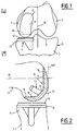
- Fig. 1 is a partial front view of a left knee in the flexed position and showing the implantation of a unicompartmental prosthesis on the internal condylar mass.
- Fig. 2 is an elevation, partly in section, taken along line II-II of FIG. 1 .
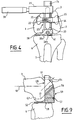
- FIG. 3 is an elevation similar to FIG. 2 , but showing part of the ancillary instrumentation according to the invention.
- Fig. 4 is a front view taken substantially along line IV-IV of FIG. 3 .
- Fig. 5 is a top view taken along line VV of FIG. 3 .
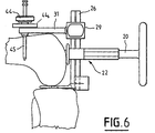
- Fig. 6 is an elevation similar to FIG. 3 , but showing an alternative embodiment.
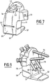
- Fig. 7 is a perspective showing, on a larger scale, another part of the ancillary instrumentation according to the invention.
- Fig. 8 is a perspective view according to another orientation of the instrumentation part according to FIG. 7 , provided with its installation equipment.
- Fig. 9 is a view similar to FIG. 3 , but showing the implementation of the instrumentation part according to FIGS. 7 and 8 .
- Figs. 1 and 2 show, diagrammatically, a left knee joint involving the cooperation of congruent surfaces, such as the inner 1 and outer 2 condyles of a femur 3 with the glenes 4 and 5 of the plateau 6 of a tibia 7 .
- the adaptation of a unicompartmental prosthesis of the femur consists in implanting, for example, in substitution for the internal condyle 1 , a unicompartmental prosthesis 8 produced in the form of a prosthetic element substantially in set square, comprising a branch 9 called distal condyle and a branch 10 called posterior condyle.
- the branches 9 and 10 together define a curved outer surface 11 , which is intended to cooperate with the upper surface of a pad 12 of a unicompartmental prosthesis of tibia 13 , only shown schematically by way of example in FIGS. 1 and 2 and implanted to replace the glenoid 4 .
- the branches 9 and 10 are defined, moreover, by rear flat surfaces 14 and 15 which, preferably, are connected by an inclined panel 16 from which or in the vicinity of which a bone insertion means 17 is provided, for example , in the form of one or more nipples.
- a unicompartmental prosthesis implies being able to perform a bone resection of the condylar mass 1 in a complementary manner to the adaptation faces 14 , 15 and 16 , while respecting the orientation relationship with the 'anatomical axis 18 of the femur and with the natural articular plane defined by the alignment of the condyles 1 and 2 considered according to an extreme distal plane, such as the plane P-P' .
- the femoral ancillary instrumentation according to the invention is precisely designed to provide operating aid specific to the performance of bone resections, necessary and complementary to the implantation of the unicompartmental prosthesis 8 .
- the ancillary femoral instrumentation firstly comprises a means 20 for centro-medullary aiming which can be engaged in the medullary canal of the femur along the anatomical axis 18 , starting from the intercondylar notch 21 (FIG. 1) .
- a medullary canal is generally the subject of a piercing which is practiced in a known manner, to allow the insertion of the means 20 .
- the means 20 is constituted by a guide rod suitable for guiding a piece 22 called support because of the function which it must assume.
- the support piece 22 comprises a central body 23 crossed by a hole 23a and extended on one side by a sheath 24 coinciding with the hole 23a and capable of being threaded onto the rod 22 .
- the central body 23 comprises, opposite the sheath 24 , two abutment members 25 which define a plane p-p ' of simultaneous contact with the distal parts of the condyles 1 and 2 of the femur, as shown in FIGS. 3 to 5 .
- the abutment members 25 including intended to materialize the plane p-p ' to define a reference position, when the instrumentation is put in place, as is apparent from what follows.
- the instrumentation further comprises a column 26 which is engaged free in a complementary housing 23b presented by the central body 23 in a direction orthogonal to that of the hole 23a .
- the column 26 once mounted in the housing 23b extends, in consideration of FIG. 3 , in a direction orthogonal to the axis of the sleeve 24 .
- the column 26 and the housing 23b are of complementary polygonal section, preventing any relative rotation.
- the column 26 has, moreover, over a median part of its length, an axial slot 27 provided for the passage of the rod 20 and to allow its movement relative to the central body 23 in a direction which is parallel to the plane p-p ' .
- the column 26 is provided, at one of its ends, with a removable interstitial tab 28 , of generally constant thickness, which extends parallel to the axis of the sheath 24 and perpendicular to the column 26 in the direction of the stop members 25 .
- the tab 28 is, for example, mounted on the column 26 by a heel 28a provided with a clamping member, such as 28b .
- the heel 28a has an interlocking complementary to the polygonal section of the column preventing any relative rotation.
- Fig. 5 shows that, according to the invention, the heel 28a is designed so that the tab 28 extends laterally, so that it can be placed in relation and vertically to a condylar mass, such as the mass 1 in the illustrated example, as shown in the following.
- the part of the column 26 extending beyond the central body 23 relative to the tab 28 carries a cutting guide slide 29 , with an adjustable axial position by means, for example, of a lever 30 or the like .
- the slide 29 is extended, in the same direction as the tab 28 , by a rule 31 (fig. 5) extending perpendicular to the column 26 .
- the rule 31 is provided for mounting, in the adjustable position, in particular by means of graduations 32 , of a distal cutting guide 33 which can be immobilized in the appropriate position by means of a locking member 34 .
- the distal cutting guide 33 comprises a body 35 extending laterally offset in the same direction as the tab 28 and parallel to the latter.
- the body 35 defines a cutting guide slot 36 , the plane of which, as shown in FIGS. 3 and 5 , is parallel to that of column 26 and to the plane p-p ' , being however situated beyond the latter with respect to column 26 .
- the body 35 is extended by a lateral bar 37 provided with holes
- the column 26 is presented facing the epiphysis of the femur with knee flexion according to FIG. 3 , to ensure the engagement of the tab 28 between the femoral condyle 1 and the complementary part whether or not paired with the tibia 7 .
- the part 22 is threaded freely on the column 26 to present the abutment members 25 in the direction of the femoral condyles 1 and 2 .
- the part 22 is placed to make the hole 23a coincide with the pierced medullary canal, so as to allow the engagement of the aiming rod 20 .
- the column 26 is then pushed to engage the tab 28 more deeply and bring the plane p-p ' into contact with the distal parts of the femoral condyles 1 and 2 , the plane p-p ' then being confused with the anatomical alignment P-P' .
- the slide 29 is then mounted on the column 26 , then the guide 33 is threaded on the rule 31 .
- the slide 29 is adjusted to bring the guide into contact with the anterior face of the condylar mass 1 , then the guide is adjusted to the rule 31 , so as to determine by the plane of the slot 36 the distal cutting plane CD .
- the instrumentation is preferably immobilized by the engagement of cross-cutting pins 42 , in the holes 38 of the bar 37 whose lateral offset, the length as well as the orientation of the holes, allow penetration of the pins in an area of the condylar mass 1 which is not affected by the bone resection to be performed.
- the shim 40 may be constituted by a removable rod which is, for example, insertable in a housing 41 formed by the adaptation heel of the tab 28 .
- a suitable saw blade can then be engaged by the cutting slot 36 along a plane parallel to the coincident planes P-P ' and p-p' , so as to make the distal cut CD of the part of the condyle 1 , to a depth or thickness just necessary to receive the thickness of the branch 9 of the unicompartmental prosthesis 8 described above.
- a distal cut CD necessarily takes place over a precise, determined bone depth and in a direction which exactly corresponds to a plane parallel to the anatomical plane P-P ' .
- the terminal part of the rule 31 carries a finger 43 adjustable by a button 44 .
- the rule 31 and the tab 28 possibly supplemented by the wedge 40 , then form a vice or a clamp for immobilizing the femur.
- the finger 43 When the guide 33 is placed, as said previously, in abutment against the anterior face of the solid 1 , the finger 43 is adjusted to come into abutment against the femur and tighten it, so as to prevent any tilting of the ancillary instrumentation and any bending of the rule 31 , in particular during the positioning of the pins 42 . It can also be envisaged to associate the finger 43 with a through spindle 45 contributing, after the finger has been stopped, to the immobilization of the rule 31 . Finally, the adjustable finger may include a counter button 44b making it possible to avoid any accidental loosening.
- the part of the femoral ancillary instrumentation described above is removed in the reverse order to that described above, so as to release the knee joint and to release the plane of bone resection resulting from the distal cut of the condyle 1 .
- the preparation necessary for the adaptation and insertion of the unicompartmental prosthesis 8 then involves a second part of ancillary femoral instrumentation, as illustrated in FIGS. 7 and 8 .
- This second part of ancillary femoral instrumentation comprises a block 50 called intermediate and posterior sections.
- the block 50 is produced in the form of a solid piece or body having a flat reference face 51 from which extends an interstitial tab 52 formed in the extension of the corresponding end of the block 50 .
- the part of the block opposite to the tab 52 has through cylindrical bores 53 , for example four in number, which are made in different directions to allow the engagement of pins 54 for temporary bone insertion.
- the choice of the different directions is made so that the engagement of the pins 54 establishes a kind of internal triangulation favorable to a firm and resistant immobilization of the block 50 , when it is put in place as described below.
- the block 50 also has two cutting guide slots which are made from the face 55 opposite the flat face 51 , opening, preferably but not necessarily, on one of the transverse faces.
- the first cutting guide slot 56 is made at an inclination oriented towards the tab 52 and to open onto the flat face 51 .
- the second cutting guide slot 57 is formed in a manner substantially parallel to the tab 52 to open on the face 51 between the plane of the latter and the outlet from the slot 56 .
- the second slot 57 has an inclination of the order of 4 ° in the direction of the tab 52 .
- the block 50 described above is adapted on the distal part of the femur 3 , as illustrated in FIG. 8 , so that the interstitial tab 52 is engaged in the intercondylar space between the condyle 1 and the glenoid cavity 4 or the prosthesis 13 and so that the reference face 51 comes to bear with the corresponding bone resection face CD to the distal cut previously performed.
- a posterior cut CP is carried out by the same saw blade engaged in the cutting guide slot 57 to resect the posterior part of the condyle 1 over a thickness predetermined by the conformation of the block 50 and corresponding to that of the branch 10 of prosthesis 8 .
- the block 50 can then be extracted by disengaging the pins 54 to expose the three planes of bone resection, CD , CI , CP , executed on the condyle 1 to form the counterpart for adaptation and reception of the rear faces 14 , 15 and 16 of prosthesis 8 .
- the femoral ancillary instrumentation makes it possible to use reference planes corresponding exactly to the anatomical characteristics of the joint concerned, to perform bone resections of just sufficient thickness and complementary to the implantation of the unicompartmental prosthesis, such as 8 .
- the means used make it possible to protect the environment of the joint against sawing accidents liable to occur and, in particular, to preserve the integrity of the tibial plateau 4 or of the prosthesis 13 by the presence of the interstitial tab 28 and the tab 52 which assumes the same function as the tab 28 for the intermediate cut along the section plane CI .
- the means according to the invention allow an adaptation of application, given that it suffices to mount on the column 26 , that is the tab 28 and the guide 33 in a symmetrical and laterally offset position opposite to that which is shown. in the case of resection of the condyle 2 , either of a tab 28 and of a cutting guide 33 specially shaped for the condyle 2 .
Abstract
Description
La présente invention concerne le domaine de la chirurgie orthopédique et elle vise, plus particulièrement, le matériel mis en oeuvre à titre d'aide opératoire pour la réalisation d'interventions chirurgicales visant à substituer un système articulaire artificiel à une articulation naturelle défaillante.The present invention relates to the field of orthopedic surgery and it relates, more particularly, to the equipment used as operating aid for carrying out surgical interventions intended to replace an artificial articular system for a defective natural joint.
Dans le domaine technique général ci-dessus, il est connu, depuis longtemps déjà, de proposer des systèmes articulaires artificiels venant se substituer à l'articulation naturelle constituée par la conformation épiphysaire basse ou distale du fémur, par la conformation épiphysaire complémentaire haute ou proximale du tibia et par l'élément fémoro-patellaire.In the general technical field above, it has been known for a long time now to propose artificial articular systems which replace the natural articulation constituted by the low or distal epiphyseal conformation of the femur, by the complementary high or proximal epiphyseal conformation the tibia and the femoro-patellar element.
De telles propositions s'appuient sur la constitution d'un système articulaire artificiel, à partir de deux éléments principaux destinés à être implantés, après résection osseuse, sur la conformation épiphysaire basse du fémur et sur la conformation épiphysaire complémentaire haute du tibia.Such proposals are based on the constitution of an artificial articular system, from two main elements intended to be implanted, after bone resection, on the low epiphyseal conformation of the femur and on the complementary high epiphyseal conformation of the tibia.
Deux types de propositions de substitution peuvent être envisagés selon l'intervention devant être conduite. Il peut s'agir d'un remplacement pluricompartimental simultané, tant pour la conformation épiphysaire du fémur que pour celle du tibia, ou encore d'un remplacement unicompartimental lorsqu'une partie des surfaces congruentes de l'articulation seulement est détériorée.Two types of alternative proposals can be considered depending on the intervention to be carried out. It can be a simultaneous pluricompartmental replacement, both for the epiphyseal conformation of the femur and that of the tibia, or even a unicompartmental replacement when only part of the congruent surfaces of the joint is deteriorated.
L'invention concerne spécifiquement le domaine de la chirurgie orthopédique fémorale et le matériel spécifique pour la réalisation de la résection unicompartimentale d'un massif condylien fémoral, interne ou externe, préalablement à l'implantation d'une prothèse unicompartimentale.The invention relates specifically to the field of femoral orthopedic surgery and to specific equipment for carrying out unicompartmental resection of a femoral condylar mass, internal or external, prior to the implantation of a unicompartmental prosthesis.
Dans une telle situation, l'intervention consiste alors à adapter après résection des parties congruentes unicompartimentales et complémentaires de l'articulation concernée, une prothèse unicompartimentale du tibia et une prothèse unicompartimentale du massif condylien concerné du fémur.In such a situation, the intervention then consists in adapting, after resection of the unicompartmental and complementary congruent parts of the joint concerned, a unicompartmental prosthesis of the tibia and a unicompartmental prosthesis of the condylar mass concerned of the femur.
Une intervention, du type ci-dessus, concerne obligatoirement une masse osseuse qui est de plus faible importance que celle intéressée par l'implantation d'une prothèse pluricompartimentale. Il est donc particulièrement important de pouvoir exécuter la ou les coupes de résection osseuse avec une précision certaine pour permettre une implantation d'une prothèse unicompartimentale dont la faible épaisseur et la largeur réduite exigent une implantation précise respectant les caractéristiques anatomiques de l'articulation et, notamment, celles régissant le bon fonctionnement de l'articulation semi-artificielle et semi-naturelle qui en résultera.An intervention, of the above type, necessarily involves a bone mass which is of less importance than that interested in the implantation of a multi-compartment prosthesis. It is therefore particularly important to be able to execute the bone resection cut (s) with certain precision to allow implantation of a unicompartmental prosthesis whose thin thickness and reduced width require precise implantation respecting the anatomical characteristics of the joint and, in particular, those governing the proper functioning of the semi-artificial and semi-natural joint that will result therefrom.
Il convient, en effet, de considérer que dans une telle situation, l'obligation à respecter est de pouvoir implanter une prothèse unicompartimentale, de manière qu'elle vienne compléter le compartiment naturel subsistant dans la fonctionnalité de l'articulation et qu'elle puisse présenter, dans le temps et malgré les sollicitations qu'elle subit, une implantation osseuse ferme et résistante, garantissant une bonne tenue dans le temps.It should indeed be considered that in such a situation, the obligation to be respected is to be able to implant a unicompartmental prosthesis, so that it comes to complement the natural compartment remaining in the functionality of the joint and that it can present, over time and despite the stresses it undergoes, a firm and resistant bone implantation, guaranteeing good resistance over time.
Si des prothèses unicompartimentales, du genre ci-dessus, ont déjà été proposées dans la technique orthopédique, en revanche, il peut être considéré que l'instrumentation ancillaire existante ne permet pas de respecter justement la conduite avec précision des différentes coupes de résection osseuse qu'il convient d'exécuter pour assurer une mise en place d'une telle prothèse répondant aux objectifs ci-dessus.If unicompartmental prostheses, of the above kind, have already been proposed in the orthopedic technique, on the other hand, it can be considered that the existing ancillary instrumentation does not allow to precisely respect the conduct with precision of the different cuts of bone resection that '' it is necessary to perform to ensure the installation of such a prosthesis meeting the above objectives.
La demande EP 0 538 153 décrit, par exemple, un ancillaire fémoral pour l'exécution d'une résection bicompartimentale du fémur. Cet ancillaire comprend, notamment :
- une colonne pourvue, à une extrémité, de deux pattes interstitielles destinées à être engagées dans les intervalles intercondyliens,
- une pièce d'appui empilable sur la colonne et comportant, dans la même direction que la patte, deux organes de butée définissant un plan de contact simultané avec les parties distales du fémur et, à l'opposé de ces organes, un fourreau tubulaire traversant la pièce,
- un guide de coupe réglable sur une règle montée sur la colonne à l'opposé de la patte par rapport à la pièce d'appui et s'étendant latéralement par rapport à la colonne et parallèlement au plan d'appui, pour permettre l'exécution, selon une orientation parallèle audit plan, de la coupe distale (CD) des compartiments condyliens, le guide de coupe comportant des perçages permettant l'engagement de broches d'immobilisation dans les deux massifs du fémur,
- et une tige de visée centro-médullaire engageable dans le fourreau et dans le canal médullaire du fémur à partir de l'échancrure intercondylienne.
- a column provided, at one end, with two interstitial legs intended to be engaged in the intercondylar intervals,
- a support piece stackable on the column and comprising, in the same direction as the leg, two abutment members defining a plane of simultaneous contact with the distal parts of the femur and, opposite these members, a tubular sheath passing through the room,
- an adjustable cutting guide on a ruler mounted on the column opposite the leg relative to the support piece and extending laterally relative to the column and parallel to the support plane, to allow execution , in an orientation parallel to said plane, of the distal section ( CD ) of the condylar compartments, the section guide having holes allowing the engagement of immobilization pins in the two massifs of the femur,
- and a centro-medullary aiming rod which can be engaged in the sheath and in the medullary canal of the femur from the intercondylar notch.
Selon cette demande EP 0 538 153, l'immobilisation finale du guide de coupe avant résection est effectuée au moyen de broches engagées dans les deux massifs du fémur. Or, pour la mise en place d'une prothèse unicompartimentale, il est nécessaire de ne pas altérer le compartiment sain de l'articulation. De plus, pour offrir à une telle prothèse des conditions d'implantation les meilleures possibles, il convient de rechercher, autant que faire se peut, des points d'ancrage n'affectant pas la partie du massif osseux devant être réséquée. Enfin, l'ancillaire doit comporter, en outre, des moyens d'immobilisation fiables qui garantissent l'invariabilité de sa position par rapport au fémur pendant toute l'exécution de la résection.According to this application EP 0 538 153, the final immobilization of the cutting guide before resection is carried out by means of pins engaged in the two masses of the femur. However, for the establishment of a unicompartmental prosthesis, it is necessary not to alter the healthy compartment of the joint. In addition, in order to provide such a prosthesis with the best possible implantation conditions, it is advisable to seek, as far as possible, anchoring points which do not affect the part of the bone mass to be resected. Finally, the ancillary must include, in addition, reliable immobilization means which guarantee the invariability of its position relative to the femur during the entire execution of the resection.
Il semble que l'art antérieur ne propose pas d'instrumentation ancillaire répondant à l'ensemble de ces exigences, pourtant complémentaires.It seems that the prior art does not propose ancillary instrumentation meeting all of these requirements, which are however complementary.
L'objet de l'invention est justement de combler cette lacune en proposant une instrumentation ancillaire fémorale qui soit propre à l'implantation d'une prothèse unicompartimentale du fémur dont la conception est justement prévue aussi pour permettre une bonne implantation sans conduire à une résection compartimentale osseuse importante.The object of the invention is precisely to fill this gap by proposing an ancillary femoral instrumentation which is specific to the implantation of a unicompartmental prosthesis of the femur whose design is precisely also intended to allow a good implantation without leading to resection. significant bone compartmentality.
L'objet de l'invention est de proposer une instrumentation ancillaire fémorale, simple de conception et d'utilisation et dont les moyens techniques permettent de déterminer avec précision l'orientation, l'alignement et la position des moyens d'aide à l'implantation permettant de réaliser des résections osseuses selon des plans relatifs, favorables à la bonne implantation d'une prothèse unicompartimentale du fémur.The object of the invention is to propose a femoral ancillary instrumentation, simple to design and use, the technical means of which make it possible to precisely determine the orientation, alignment and position of the aid means implantation allowing bone resections to be carried out according to relative plans, favorable to the correct implantation of a unicompartmental prosthesis of the femur.
L'objet de l'invention vise une instrumentation ancillaire fémorale à même de favoriser le travail préparatoire du chirurgien, en lui fournissant des axes et plans de référence et d'appui, à position, orientation ou sens, éventuellement réglables, définissant un domaine référentiel précis à partir duquel une implantation de prothèse fémorale unicompartimentale peut être réalisée avec une sécurité maximale.The object of the invention is to provide ancillary femoral instrumentation capable of promoting the preparatory work of the surgeon, by providing him with axes and reference and support planes, in position, orientation or direction, possibly adjustable, defining a referential field. precision from which implantation of a unicompartmental femoral prosthesis can be performed with maximum safety.
Pour atteindre les objectifs ci-dessus, l'instrumentation ancillaire fémorale est caractérisée en ce qu'elle comprend :
- un guide de coupe distale comportant une barrette latérale pourvue de trous pour l'engagement de broches,
- et un bloc de coupes postérieure et intermédiaire adaptable par broches sur la coupe distale.
- a distal cutting guide comprising a lateral bar provided with holes for the engagement of pins,
- and a block of posterior and intermediate cuts adaptable by pins on the distal cut.
Diverses autres caractéristiques ressortent de la description faite ci-dessous en référence aux dessins annexés qui montrent, à titre d'exemples non limitatifs, des formes de réalisation de l'objet de l'invention.Various other characteristics will emerge from the description given below with reference to the appended drawings which show, by way of nonlimiting examples, embodiments of the subject of the invention.
La fig. 1 est une vue de face partielle d'un genou gauche en position fléchie et montrant l'implantation d'une prothèse unicompartimentale sur le massif condylien interne. Fig. 1 is a partial front view of a left knee in the flexed position and showing the implantation of a unicompartmental prosthesis on the internal condylar mass.
La fig. 2 est une élévation, partie en coupe, prise selon la ligne II-II de la fig. 1. Fig. 2 is an elevation, partly in section, taken along line II-II of FIG. 1 .
La fig. 3 est une élévation analogue à la fig. 2, mais montrant une partie de l'instrumentation ancillaire conforme à l'invention. Fig. 3 is an elevation similar to FIG. 2 , but showing part of the ancillary instrumentation according to the invention.
La fig. 4 est une vue de face prise sensiblement selon la ligne IV-IV de la fig. 3. Fig. 4 is a front view taken substantially along line IV-IV of FIG. 3 .
La fig. 5 est une vue de dessus prise selon la ligne V-V de la fig. 3. Fig. 5 is a top view taken along line VV of FIG. 3 .
La fig. 6 est une élévation analogue à la fig. 3, mais montrant une variante de réalisation. Fig. 6 is an elevation similar to FIG. 3 , but showing an alternative embodiment.
La fig. 7 est une perspective montrant, à plus grande échelle, une autre partie de l'instrumentation ancillaire conforme à l'invention. Fig. 7 is a perspective showing, on a larger scale, another part of the ancillary instrumentation according to the invention.
La fig. 8 est une perspective vue selon une autre orientation de la partie d'instrumentation selon la fig. 7, pourvue de son équipement d'implantation. Fig. 8 is a perspective view according to another orientation of the instrumentation part according to FIG. 7 , provided with its installation equipment.
La fig. 9 est une vue analogue à la fig. 3, mais montrant la mise en oeuvre de la partie d'instrumentation selon les fig. 7 et 8. Fig. 9 is a view similar to FIG. 3 , but showing the implementation of the instrumentation part according to FIGS. 7 and 8 .
Les fig. 1 et 2 montrent, de façon schématique, une articulation de genou gauche faisant intervenir la coopération de surfaces congruentes, tels que les condyles interne 1 et externe 2 d'un fémur 3 avec les glènes 4 et 5 du plateau 6 d'un tibia 7. Figs. 1 and 2 show, diagrammatically, a left knee joint involving the cooperation of congruent surfaces, such as the inner 1 and outer 2 condyles of a
Dans une articulation naturelle, du type ci-dessus, l'adaptation d'une prothèse unicompartimentale du fémur consiste à implanter, par exemple, en substitution du condyle interne 1, une prothèse unicompartimentale 8 réalisée sous la forme d'un élément prothétique sensiblement en équerre, comportant une branche 9 dite de condyle distal et une branche 10 dite de condyle postérieur. Les branches 9 et 10 définissent ensemble une surface extérieure 11 courbe, qui est destinée à coopérer avec la surface supérieure d'un patin 12 d'une prothèse unicompartimentale de tibia 13, uniquement schématisée à titre d'exemple aux fig. 1 et 2 et implantée en remplacement de la glène 4. Les branches 9 et 10 sont définies, par ailleurs, par des surfaces planes arrières 14 et 15 qui, de préférence, sont raccordées par un pan incliné 16 à partir duquel ou au voisinage duquel un moyen d'insertion osseuse 17 est prévu, par exemple, sous la forme d'un ou de plusieurs tétons.In a natural joint, of the above type, the adaptation of a unicompartmental prosthesis of the femur consists in implanting, for example, in substitution for the
L'implantation d'une prothèse unicompartimentale, du type ci-dessus, implique de pouvoir réaliser une résection osseuse du massif condylien 1 de manière complémentaire aux face d'adaptation 14, 15 et 16, tout en respectant la relation d'orientation avec l'axe anatomique 18 du fémur et avec le plan articulaire naturel défini par l'alignement des condyles 1 et 2 considérés selon un plan distal extrême, tel que le plan P-P'.The implantation of a unicompartmental prosthesis, of the above type, implies being able to perform a bone resection of the
L'instrumentation ancillaire fémorale selon l'invention est justement conçue pour fournir une aide opératoire propre à l'exécution des résections osseuses, nécessaires et complémentaires à l'implantation de la prothèse unicompartimentale 8.The femoral ancillary instrumentation according to the invention is precisely designed to provide operating aid specific to the performance of bone resections, necessary and complementary to the implantation of the
Ce qui vaut pour le cas d'une prothèse 8 interne de genou gauche vaut également pour une prothèse interne de genou droit, qui peut être considérée comme symétrique par rapport à un plan sagittal et, toute adaptation nécessaire étant prévue, également pour une prothèse unicompartimentale externe gauche ou externe droite pour les mêmes raisons. L'instrumentation ancillaire fémorale est justement prévue pour répondre à un tel besoin global, en faisant intervenir des moyens technique principaux valant pour toutes les applications et en ne prévoyant, en fonction des compartiments articulaires visés, que des adaptations partielles de pièces élémentaires, sans que ces adaptations aient une incidence sur la combinaison globale des moyens techniques mis en oeuvre.What applies to the case of an
L'instrumentation ancillaire fémorale comprend tout d'abord un moyen 20 de visée centro-médullaire qui est engageable dans le canal médullaire du fémur selon l'axe anatomique 18, à partir de l'échancrure intercondylienne 21 (fig. 1). Un tel canal médullaire fait généralement l'objet d'un percement qui est pratiqué de manière connue, pour permettre l'insertion du moyen 20.The ancillary femoral instrumentation firstly comprises a
Selon une disposition de l'invention, le moyen 20 est constitué par une tige-guide propre à assurer le guidage d'une pièce 22 dite d'appui en raison de la fonction qu'elle doit assumer. La pièce d'appui 22 comporte un corps central 23 traversé par un trou 23a et prolongé d'un côté par un fourreau 24 coïncidant avec le trou 23a et susceptible d'être enfilé sur la tige 22. Le corps central 23 comporte à l'opposé du fourreau 24, deux organes de butée 25 qui définissent un plan p-p' de contact simultané avec les parties distales des condyles 1 et 2 du fémur, tel que cela ressort des fig. 3 à 5. Les organes de butée 25 dont destinés à matérialiser le plan p-p' pour définir une position de référence, lors de la mise en place de l'instrumentation, comme cela ressort de ce qui suit.According to a provision of the invention, the
L'instrumentation comprend, par ailleurs, une colonne 26 qui est engagée libre dans un logement 23b complémentaire présenté par le corps central 23 selon une direction orthogonale à celle du trou 23a. La colonne 26, une fois montée dans le logement 23b s'étend, en considération de la fig. 3, selon une direction orthogonale à l'axe du fourreau 24. La colonne 26 et le logement 23b sont de section polygonale complémentaire, interdisant toute rotation relative. La colonne 26 présente, par ailleurs, sur une partie médiane de sa longueur, une lumière 27 axiale prévue pour le passage de la tige 20 et pour autoriser son déplacement par rapport au corps central 23 selon une direction qui est parallèle au plan p-p'.The instrumentation further comprises a
La colonne 26 est munie, à l'une de ses extrémités, d'une patte interstitielle 28 amovible, d'épaisseur généralement constante, qui s'étend parallèlement à l'axe du fourreau 24 et perpendiculairement à la colonne 26 dans la direction des organes de butée 25. La patte 28 est, par exemple, montée sur la colonne 26 par un talon 28a pourvu d'un organe de serrage, tel que 28b. Le talon 28a présente un emboîtement complémentaire à la section polygonale de la colonne interdisant toute rotation relative.The
La fig. 5 permet de constater que, selon l'invention, le talon 28a est conçu pour que la patte 28 s'étende latéralement, de manière à pouvoir être placée en relation et à l'aplomb d'un massif condylien, tel que le massif 1 dans l'exemple illustré, comme cela apparaît dans ce qui suit. Fig. 5 shows that, according to the invention, the
La partie de la colonne 26 s'étendant au delà du corps central 23 par rapport à la patte 28 porte un coulisseau porte-guide de coupe 29, à position axiale réglable par l'intermédiaire, par exemple, d'une manette 30 ou analogue. Le coulisseau 29 est prolongé, dans le même sens que la patte 28, par une règle 31 (fig. 5) s'étendant perpendiculairement à la colonne 26. La règle 31 est prévue pour le montage, en position réglable, notamment par l'intermédiaire de graduations 32, d'un guide de coupe distale 33 pouvant être immobilisé en position appropriée par l'intermédiaire d'un organe de blocage 34. Le guide de coupe distale 33 comprend un corps 35 s'étendant de façon latéralement déportée dans le même sens que la patte 28 et parallèlement à cette dernière. Le corps 35 délimite une fente guide de coupe 36 dont le plan, tel que cela apparaît aux fig. 3 et 5, est parallèle à celui de la colonne 26 et au plan p-p', en étant situé toutefois au-delà de ce dernier par rapport à la colonne 26. Le corps 35 est prolongé par une barrette latérale 37 pourvue de trous 38 dont la fonction apparaît dans ce qui suit.The part of the
La mise en oeuvre de la partie d'instrumentation ancillaire fémorale décrite ci-dessus est assurée de la façon suivante pour l'exécution de la résection osseuse distale du condyle 1 interne d'un genou gauche.The implementation of the femoral ancillary instrumentation part described above is ensured in the following manner for the execution of the distal bone resection of the
Après le percement du canal centro-médullaire selon l'axe anatomique 18, la colonne 26 est présentée face à l'épiphyse du fémur avec flexion du genou selon la fig. 3, pour assurer l'engagement de la patte 28 entre le condyle fémoral 1 et la partie complémentaire appareillée ou non du tibia 7. La pièce 22 est enfilée librement sur la colonne 26 pour présenter les organes de butée 25 en direction des condyles fémoraux 1 et 2. La pièce 22 est placée pour mettre en coïncidence le trou 23a avec le canal médullaire percé, de manière à permettre l'engagement de la tige de visée 20.After the piercing of the central medullary canal along the
La colonne 26 est alors poussée pour engager plus profondément la patte 28 et amener le plan p-p' en contact avec les parties distales des condyles fémoraux 1 et 2, le plan p-p' étant alors confondu avec l'alignement anatomique P-P'.The
Le coulisseau 29 est ensuite monté sur la colonne 26, puis le guide 33 est enfilé sur la règle 31. Le coulisseau 29 est réglé pour amener le guide en contact avec la face antérieure du massif condylien 1, puis le guide est réglé sur la règle 31, de manière à déterminer par le plan de la fente 36 le plan de coupe distale CD.The
Dans cet état, l'instrumentation est préférablement immobilisée par l'engagement de broches transosseuses 42, dans les trous 38 de la barrette 37 dont le déport latéral, la longueur ainsi que l'orientation des trous, permettent une pénétration des broches dans une zone du massif condylien 1 qui n'est pas concernée par la résection osseuse devant être pratiquée.In this state, the instrumentation is preferably immobilized by the engagement of
Pour disposer d'un équilibre d'orientation, il peut être envisagé d'assurer l'insertion interstitielle d'une cale d'épaisseur 40 dans l'intervalle intercondylien entre le condyle 2 et la glène 5. La cale d'épaisseur 40 peut être constituée par une tige amovible qui est, par exemple, insérable dans un logement 41 ménagé par le talon d'adaptation de la patte 28.To have an orientation balance, it can be envisaged to ensure the interstitial insertion of a shim of
Une lame de scie appropriée peut alors être engagée par la fente de coupe 36 selon un plan parallèle aux plans confondus P-P' et p-p', de manière à réaliser la coupe distale CD de la partie du condyle 1, sur une profondeur ou une épaisseur juste nécessaire pour recevoir l'épaisseur de la branche 9 de la prothèse unicompartimentale 8 décrite précédemment.A suitable saw blade can then be engaged by the cutting
Etant donné que le plan de la fente 36 est réglé avec précision par l'organe 34 parallèlement aux plans P-P' et p-p', une coupe distale CD intervient obligatoirement sur une profondeur osseuse précise, déterminée et selon une direction qui correspond exactement à un plan parallèle au plan anatomique P-P'.Since the plane of the
Pour que le plan de la fente 36 soit exactement orienté parallèlement aux plans confondus P-P' et p-p', il peut être avantageux de prolonger la règle 31, comme montré par la fig. 6. Dans cette variante, la partie terminale de la règle 31 porte un doigt 43 réglable par un bouton 44. La règle 31 et la patte 28, éventuellement complétée par la cale 40, forment alors un étau ou une pince d'immobilisation du fémur. Lorsque le guide 33 est placé, comme dit précédemment, en butée contre la face antérieure du massif 1, le doigt 43 est réglé pour venir en butée contre le fémur et le serrer, de manière à empêcher tout basculement de l'instrumentation ancillaire et toute flexion de la règle 31, notamment lors de la mise en place des broches 42. Il peut être envisagé aussi d'associer le doigt 43 à une broche traversante 45 contribuant, après mise en butée du doigt, à l'immobilisation de la règle 31. Enfin, le doigt réglable peut comporter un contre-bouton 44b permettant d'éviter tout desserrage accidentel.So that the plane of the
Il doit être remarqué que l'exécution de cette résection osseuse selon le plan CD n'intéresse que la partie distale du condyle 1 et qu'elle peut être conduite en toute sécurité, sans risque de pénétration intempestive dans la glène 4 complémentaire du tibia 7 ou dans la prothèse 13, étant donné que la patte interstitielle 28 constitue une butée positive pour l'extrémité de la scie.It should be noted that the execution of this bone resection according to the CD plan only interests the distal part of the
Lorsque la coupe distale CD a été effectuée, la partie de l'instrumentation ancillaire fémorale décrite ci-dessus est ôtée en procédant de façon inverse à ce qui est décrit précédemment, de manière à libérer l'articulation du genou et à dégager le plan de résection osseuse résultant de la coupe distale du condyle 1.When the distal CD cut has been performed, the part of the femoral ancillary instrumentation described above is removed in the reverse order to that described above, so as to release the knee joint and to release the plane of bone resection resulting from the distal cut of the
La préparation nécessaire à l'adaptation et l'insertion de la prothèse unicompartimentale 8 fait alors intervenir une deuxième partie d'instrumentation ancillaire fémorale, telle qu'illustrée par les fig. 7 et 8. Cette seconde partie d'instrumentation ancillaire fémorale comprend un bloc 50 dit de coupes intermédiaire et postérieure. Le bloc 50 est réalisé sous la forme d'une pièce ou d'un corps massif possédant une face plane de référence 51 à partir de laquelle s'étend une patte interstitielle 52 ménagée dans le prolongement de l'extrémité correspondante du bloc 50.The preparation necessary for the adaptation and insertion of the
La partie du bloc opposée à la patte 52 présente des alésages cylindriques traversants 53, par exemple au nombre de quatre, qui sont pratiqués suivant des directions différentes pour permettre l'engagement de broches 54 d'insertion osseuse temporaire. Le choix des directions différentes est effectué pour que l'engagement des broches 54 établisse une sorte de triangulation interne favorable à une immobilisation ferme et résistante du bloc 50, lors de sa mise en place comme exposé ci-après.The part of the block opposite to the
Le bloc 50 présente, par ailleurs, deux fentes-guides de coupe qui sont pratiquées à partir de la face 55 opposée à la face plane 51, en débouchant, de préférence mais non obligatoirement, sur l'une des faces transversales. La première fente-guide de coupe 56 est pratiquée selon une inclinaison orientée vers la patte 52 et pour déboucher sur la face plane 51. La seconde fente-guide de coupe 57 est pratiquée de façon sensiblement parallèle à la patte 52 pour s'ouvrir sur la face 51 entre le plan de cette dernière et la sortie de la fente 56. De manière préférée, la seconde fente 57 présente une inclinaison de l'ordre de 4° en direction de la patte 52.The
Le bloc 50 décrit ci-dessus est adapté sur la partie distale du fémur 3, tel que cela est illustré par la fig. 8, de manière que la patte interstitielle 52 soit engagée dans l'espace intercondylien entre le condyle 1 et la cavité glénoïde 4 ou la prothèse 13 et de telle sorte que la face de référence 51 vienne prendre appui avec la face de résection osseuse CD correspondant à la coupe distale précédemment exécutée.The
Dans cette position, l'immobilisation du bloc 50 est assurée par l'engagement des broches 54 dans les différents alésages 53.In this position, immobilization of the
Par l'intermédiaire d'une scie engagée à partir de la face 55 du bloc 50, il peut alors être procédé à l'exécution, par l'intermédiaire de la fente 56, d'une résection intermédiaire visant à ménager un chanfrein dans le condyle 1 à partir de la coupe distale CD, de telle sorte que soit produite, comme illustré en traits mixtes à la fig. 3, une coupe intermédiaire CI, complémentaire au pan incliné 16 de la prothèse 8.By means of a saw engaged from the
De la même manière, une coupe postérieure CP est exécutée par une même lame de scie engagée dans la fente-guide de coupe 57 pour réséquer la partie postérieure du condyle 1 sur une épaisseur prédéterminée par la conformation du bloc 50 et correspondant à celle de la branche 10 de la prothèse 8.In the same way, a posterior cut CP is carried out by the same saw blade engaged in the cutting
Le bloc 50 peut ensuite être extrait par dégagement des broches 54 pour mettre à nu les trois plans de résection osseuse, CD, CI, CP, exécutés sur le condyle 1 pour former la contrepartie d'adaptation et de réception des faces arrières 14, 15 et 16 de la prothèse 8.The
Il convient de noter que dans cette phase préparatoire, seules les faces d'appui et de réception CD, CI et CP ont été exécutées, de sorte qu'il est possible de faire intervenir une phase d'adaptation intermédiaire consistant à placer, sur ces faces de résection osseuse, un gabarit de pose correspondant à la forme exacte de la prothèse 8 retenue et devant être implantée.It should be noted that in this preparatory phase, only the support and reception faces CD , CI and CP were executed, so that it is possible to do intervene an intermediate adaptation phase consisting in placing, on these bone resection faces, a fitting template corresponding to the exact shape of the
Le cas échéant, il est possible de procéder à toute réadaptation de surface complémentaire au moyen d'une râpe ou analogue, pour parfaire la complémentarité des faces CD, CI, CP et 14, 16, et 15 avant de procéder au percement dans le massif condylien du ou des trous borgnes destinés à recevoir les moyens d'insertion, tels que 17.If necessary, it is possible to carry out any additional surface rehabilitation by means of a rasp or the like, to perfect the complementarity of the CD , CI , CP and 14 , 16 , and 15 faces before drilling into the solid mass. condylar of the blind hole or holes intended to receive the insertion means, such as 17 .
Ainsi que cela ressort des moyens décrits et de leur mise en service, l'instrumentation ancillaire fémorale, conforme à l'invention, permet de faire intervenir des plans de référence correspondant exactement aux caractéristiques anatomiques de l'articulation concernée, pour exécuter des résections osseuses d'épaisseur juste suffisante et complémentaires à l'implantation de la prothèse unicompartimentale, telle que 8.As is apparent from the means described and from their commissioning, the femoral ancillary instrumentation, in accordance with the invention, makes it possible to use reference planes corresponding exactly to the anatomical characteristics of the joint concerned, to perform bone resections of just sufficient thickness and complementary to the implantation of the unicompartmental prosthesis, such as 8 .
De même, l'exécution de ces plans offre une possibilité de correction ultérieure par contrôle d'un gabarit de pose à partir duquel seulement, le ou les percements d'insertion sont exécutés avec la sécurité maximale.Likewise, the execution of these plans offers a possibility of subsequent correction by checking a laying template from which only the insertion hole (s) are executed with maximum security.
Les moyens mis en oeuvre permettent de protéger l'environnement de l'articulation contre les accidents de sciage susceptibles d'intervenir et, notamment, de préserver l'intégrité du plateau tibial 4 ou de la prothèse 13 par la présence de la patte interstitielle 28 et de la patte 52 laquelle assume la même fonction que la patte 28 pour la coupe intermédiaire selon le plan de coupe CI.The means used make it possible to protect the environment of the joint against sawing accidents liable to occur and, in particular, to preserve the integrity of the tibial plateau 4 or of the
Les moyens selon l'invention permettent une adaptation d'application, étant donné qu'il suffit de monter sur la colonne 26, soit la patte 28 et le guide 33 dans une position symétrique et latéralement déportée à l'opposé de ce qui est représenté dans le cas de la résection du condyle 2, soit d'une patte 28 et d'un guide de coupe 33 spécialement conformés pour le condyle 2.The means according to the invention allow an adaptation of application, given that it suffices to mount on the
Ce qui vaut pour les condyles 1 et 2 d'un fémur gauche, vaut également pour ceux interne et externe d'un genou droit.What applies to
Il en est de même pour ce qui concerne la partie de l'instrumentation constituée par le bloc 50 qui est réalisé de façon symétrique et complémentaire pour l'exécution des résections osseuses CI et CP du condyle 2 ou des condyles interne et externe d'un genou droit.It is the same with regard to the part of the instrumentation constituted by the
L'invention n'est pas limitée aux exemples décrits et représentés car diverses modifications peuvent y être apportées sans sortir de son cadre.The invention is not limited to the examples described and shown since various modifications can be made thereto without departing from its scope.
Claims (9)
caractérisée en ce qu'elle comprend :
characterized in that it comprises:
Applications Claiming Priority (2)
| Application Number | Priority Date | Filing Date | Title |
|---|---|---|---|
| FR9413095A FR2726178B1 (en) | 1994-10-27 | 1994-10-27 | FEMALE ANCILLARY INSTRUMENTATION FOR THE IMPLANTATION OF A UNICOMPARTMENTAL KNEE PROSTHESIS |
| FR9413095 | 1994-10-27 |
Publications (2)
| Publication Number | Publication Date |
|---|---|
| EP0709061A1 true EP0709061A1 (en) | 1996-05-01 |
| EP0709061B1 EP0709061B1 (en) | 2003-07-02 |
Family
ID=9468436
Family Applications (1)
| Application Number | Title | Priority Date | Filing Date |
|---|---|---|---|
| EP95420299A Expired - Lifetime EP0709061B1 (en) | 1994-10-27 | 1995-10-27 | Femoral ancillary instrumentation for implanting a unicompartmental knee prosthesis |
Country Status (5)
| Country | Link |
|---|---|
| EP (1) | EP0709061B1 (en) |
| AT (1) | ATE243977T1 (en) |
| DE (1) | DE69531184T2 (en) |
| ES (1) | ES2201090T3 (en) |
| FR (1) | FR2726178B1 (en) |
Cited By (31)
| Publication number | Priority date | Publication date | Assignee | Title |
|---|---|---|---|---|
| WO1999027860A1 (en) * | 1997-12-01 | 1999-06-10 | Eska Implants Gmbh & Co. | System for reconstructing torque between the natural knee and an area of the natural hip |
| FR2778083A1 (en) * | 1998-04-29 | 1999-11-05 | Patrick Hechard | Positioning device for knee-prosthesis location |
| WO2000000093A1 (en) * | 1998-06-29 | 2000-01-06 | Plus Endoprothetik Ag | Device and method for inserting a prosthetic knee |
| US6482209B1 (en) | 2001-06-14 | 2002-11-19 | Gerard A. Engh | Apparatus and method for sculpting the surface of a joint |
| WO2003013373A1 (en) * | 2001-08-10 | 2003-02-20 | Depuy International Limited | Guide for locating femur resection plane |
| FR2837692A1 (en) * | 2002-03-26 | 2003-10-03 | Bertrand Bergue | Femur resection guide for fitting component of knee prosthesis has base with positioners for centro-medullary rod and sliding support |
| US6723102B2 (en) | 2001-06-14 | 2004-04-20 | Alexandria Research Technologies, Llc | Apparatus and method for minimally invasive total joint replacement |
| EP1470786A1 (en) * | 2003-04-25 | 2004-10-27 | Centerpulse Orthopedics Ltd. | Device for preparation of a femoral condyle |
| US7527630B2 (en) | 2003-04-25 | 2009-05-05 | Zimmer, Gmbh | Apparatus for the preparation of a femoral condyle |
| US7569060B2 (en) | 2003-04-25 | 2009-08-04 | Zimmer, Gmbh | Apparatus for the fixing of the position of bone cuts |
| US7648510B2 (en) | 2003-09-15 | 2010-01-19 | Zimmer, Gmbh | Adjustment apparatus |
| US7686813B2 (en) | 2003-05-06 | 2010-03-30 | Zimmer, Gmbh | Traction apparatus |
| WO2011131983A2 (en) | 2010-04-20 | 2011-10-27 | Biomet Ltd. | Unicondylar knee replacement |
| EP2387367A1 (en) * | 2008-12-16 | 2011-11-23 | Otismed Corporation | Unicompartmental customized arthroplasty cutting jigs and methods of making the same |
| US8454616B2 (en) | 2002-11-27 | 2013-06-04 | Zimmer, Inc. | Method and apparatus for achieving correct limb alignment in unicondylar knee arthroplasty |
| US8968320B2 (en) | 2007-12-18 | 2015-03-03 | Otismed Corporation | System and method for manufacturing arthroplasty jigs |
| US9017336B2 (en) | 2006-02-15 | 2015-04-28 | Otismed Corporation | Arthroplasty devices and related methods |
| US9208263B2 (en) | 2008-04-30 | 2015-12-08 | Howmedica Osteonics Corporation | System and method for image segmentation in generating computer models of a joint to undergo arthroplasty |
| US9402637B2 (en) | 2012-10-11 | 2016-08-02 | Howmedica Osteonics Corporation | Customized arthroplasty cutting guides and surgical methods using the same |
| US9408618B2 (en) | 2008-02-29 | 2016-08-09 | Howmedica Osteonics Corporation | Total hip replacement surgical guide tool |
| US9451970B2 (en) | 2008-07-23 | 2016-09-27 | Howmedica Osteonics Corporation | Arthroplasty jigs with mating accuracy |
| US9610086B2 (en) | 2002-05-15 | 2017-04-04 | Howmedica Osteonics Corporation | Method of manufacturing an arthroplasty jig |
| US9646113B2 (en) | 2008-04-29 | 2017-05-09 | Howmedica Osteonics Corporation | Generation of a computerized bone model representative of a pre-degenerated state and useable in the design and manufacture of arthroplasty devices |
| US9649170B2 (en) | 2007-12-18 | 2017-05-16 | Howmedica Osteonics Corporation | Arthroplasty system and related methods |
| US9782226B2 (en) | 2007-12-18 | 2017-10-10 | Howmedica Osteonics Corporation | Preoperatively planning an arthroplasty procedure and generating a corresponding patient specific arthroplasty resection guide |
| US10206688B2 (en) | 2006-02-15 | 2019-02-19 | Howmedica Osteonics Corporation | Arthroplasty devices and related methods |
| US10582934B2 (en) | 2007-11-27 | 2020-03-10 | Howmedica Osteonics Corporation | Generating MRI images usable for the creation of 3D bone models employed to make customized arthroplasty jigs |
| WO2020138114A1 (en) * | 2018-12-25 | 2020-07-02 | 京セラ株式会社 | Surgical instrument and surgical instrument system |
| US11051829B2 (en) | 2018-06-26 | 2021-07-06 | DePuy Synthes Products, Inc. | Customized patient-specific orthopaedic surgical instrument |
| US11696768B2 (en) | 2007-09-30 | 2023-07-11 | DePuy Synthes Products, Inc. | Apparatus and method for fabricating a customized patient-specific orthopaedic instrument |
| US11950786B2 (en) | 2021-07-02 | 2024-04-09 | DePuy Synthes Products, Inc. | Customized patient-specific orthopaedic surgical instrument |
Families Citing this family (11)
| Publication number | Priority date | Publication date | Assignee | Title |
|---|---|---|---|---|
| EP1129677A3 (en) | 2000-02-29 | 2003-04-02 | Brehm, Peter | Instrumentation for manufacturing the fixation surfaces for a knee joint endoprosthesis |
| DE10113069C1 (en) * | 2001-03-15 | 2002-11-14 | Eska Implants Gmbh & Co | System for the reconstruction of the natural torqueness between the natural knee and the area of the natural hip |
| GB2447702A (en) | 2007-03-23 | 2008-09-24 | Univ Leeds | Surgical bone cutting template |
| US9173662B2 (en) | 2007-09-30 | 2015-11-03 | DePuy Synthes Products, Inc. | Customized patient-specific tibial cutting blocks |
| WO2011106400A1 (en) | 2010-02-25 | 2011-09-01 | Depuy Products, Inc. | Customized patient-specific tibial cutting blocks |
| US10149722B2 (en) | 2010-02-25 | 2018-12-11 | DePuy Synthes Products, Inc. | Method of fabricating customized patient-specific bone cutting blocks |
| ES2704658T3 (en) | 2010-02-25 | 2019-03-19 | Depuy Products Inc | Custom patient-specific bone cutting blocks |
| EP2538853A4 (en) | 2010-02-25 | 2016-07-27 | Depuy Products Inc | Customized patient-specific bone cutting blocks |
| US8672946B2 (en) | 2011-02-11 | 2014-03-18 | Biomet Manfacturing, LLC | Method and apparatus for performing knee arthroplasty |
| US8641721B2 (en) | 2011-06-30 | 2014-02-04 | DePuy Synthes Products, LLC | Customized patient-specific orthopaedic pin guides |
| JP7353059B2 (en) * | 2019-03-29 | 2023-09-29 | 京セラ株式会社 | surgical instruments |
Citations (3)
| Publication number | Priority date | Publication date | Assignee | Title |
|---|---|---|---|---|
| FR2664157A1 (en) * | 1990-07-06 | 1992-01-10 | Jbs Sa | Femoral cutting guide |
| FR2679766A1 (en) * | 1991-07-30 | 1993-02-05 | Sophia Med | Device for fitting a knee prosthesis |
| EP0538153A1 (en) | 1991-10-01 | 1993-04-21 | Impact | Modular auxiliary instrument for the implantation of a knee prosthesis |
-
1994
- 1994-10-27 FR FR9413095A patent/FR2726178B1/en not_active Expired - Fee Related
-
1995
- 1995-10-27 EP EP95420299A patent/EP0709061B1/en not_active Expired - Lifetime
- 1995-10-27 DE DE69531184T patent/DE69531184T2/en not_active Expired - Fee Related
- 1995-10-27 ES ES95420299T patent/ES2201090T3/en not_active Expired - Lifetime
- 1995-10-27 AT AT95420299T patent/ATE243977T1/en not_active IP Right Cessation
Patent Citations (3)
| Publication number | Priority date | Publication date | Assignee | Title |
|---|---|---|---|---|
| FR2664157A1 (en) * | 1990-07-06 | 1992-01-10 | Jbs Sa | Femoral cutting guide |
| FR2679766A1 (en) * | 1991-07-30 | 1993-02-05 | Sophia Med | Device for fitting a knee prosthesis |
| EP0538153A1 (en) | 1991-10-01 | 1993-04-21 | Impact | Modular auxiliary instrument for the implantation of a knee prosthesis |
Cited By (48)
| Publication number | Priority date | Publication date | Assignee | Title |
|---|---|---|---|---|
| US6413261B1 (en) | 1997-12-01 | 2002-07-02 | Eska Implants Gmbh & Co. | System for reconstructing the twist between the natural knee and the region of the natural hips |
| WO1999027860A1 (en) * | 1997-12-01 | 1999-06-10 | Eska Implants Gmbh & Co. | System for reconstructing torque between the natural knee and an area of the natural hip |
| FR2778083A1 (en) * | 1998-04-29 | 1999-11-05 | Patrick Hechard | Positioning device for knee-prosthesis location |
| US6554837B1 (en) | 1998-06-29 | 2003-04-29 | Plus Endoprothetik Ag | Device and method for inserting a prosthetic knee |
| WO2000000093A1 (en) * | 1998-06-29 | 2000-01-06 | Plus Endoprothetik Ag | Device and method for inserting a prosthetic knee |
| US7896922B2 (en) | 2001-06-14 | 2011-03-01 | Alexandria Research Technologies, Llc | Implants for partial knee arthroplasty |
| US6723102B2 (en) | 2001-06-14 | 2004-04-20 | Alexandria Research Technologies, Llc | Apparatus and method for minimally invasive total joint replacement |
| US6482209B1 (en) | 2001-06-14 | 2002-11-19 | Gerard A. Engh | Apparatus and method for sculpting the surface of a joint |
| US7604637B2 (en) | 2001-06-14 | 2009-10-20 | Alexandria Research Technologies, Llc | Apparatus and method for minimally invasive total joint replacement |
| WO2003013373A1 (en) * | 2001-08-10 | 2003-02-20 | Depuy International Limited | Guide for locating femur resection plane |
| FR2837692A1 (en) * | 2002-03-26 | 2003-10-03 | Bertrand Bergue | Femur resection guide for fitting component of knee prosthesis has base with positioners for centro-medullary rod and sliding support |
| EP1350472A1 (en) * | 2002-03-26 | 2003-10-08 | Bertrand Bergue | Equipment for resectioning a femur for setting in place a knee prosthesis femoral implant |
| US9757136B2 (en) | 2002-05-15 | 2017-09-12 | Howmedica Osteonics Corporation | Arthroplasty jig and method of performing arthroplasty |
| US9730713B2 (en) | 2002-05-15 | 2017-08-15 | Howmedica Osteonics Corporation | Arthroplasty jig |
| US9610086B2 (en) | 2002-05-15 | 2017-04-04 | Howmedica Osteonics Corporation | Method of manufacturing an arthroplasty jig |
| US8454616B2 (en) | 2002-11-27 | 2013-06-04 | Zimmer, Inc. | Method and apparatus for achieving correct limb alignment in unicondylar knee arthroplasty |
| US7569060B2 (en) | 2003-04-25 | 2009-08-04 | Zimmer, Gmbh | Apparatus for the fixing of the position of bone cuts |
| EP1470786A1 (en) * | 2003-04-25 | 2004-10-27 | Centerpulse Orthopedics Ltd. | Device for preparation of a femoral condyle |
| US7201755B2 (en) | 2003-04-25 | 2007-04-10 | Zimmer Gmbh | Apparatus for the preparation of a femoral condyle |
| AU2004201721B2 (en) * | 2003-04-25 | 2007-05-17 | Zimmer Gmbh | An apparatus for the preparation of a femoral condyle |
| US7527630B2 (en) | 2003-04-25 | 2009-05-05 | Zimmer, Gmbh | Apparatus for the preparation of a femoral condyle |
| US7686813B2 (en) | 2003-05-06 | 2010-03-30 | Zimmer, Gmbh | Traction apparatus |
| US7648510B2 (en) | 2003-09-15 | 2010-01-19 | Zimmer, Gmbh | Adjustment apparatus |
| US9017336B2 (en) | 2006-02-15 | 2015-04-28 | Otismed Corporation | Arthroplasty devices and related methods |
| US10206688B2 (en) | 2006-02-15 | 2019-02-19 | Howmedica Osteonics Corporation | Arthroplasty devices and related methods |
| US11931049B2 (en) | 2007-09-30 | 2024-03-19 | DePuy Synthes Products, Inc. | Apparatus and method for fabricating a customized patient-specific orthopaedic instrument |
| US11696768B2 (en) | 2007-09-30 | 2023-07-11 | DePuy Synthes Products, Inc. | Apparatus and method for fabricating a customized patient-specific orthopaedic instrument |
| US10582934B2 (en) | 2007-11-27 | 2020-03-10 | Howmedica Osteonics Corporation | Generating MRI images usable for the creation of 3D bone models employed to make customized arthroplasty jigs |
| US9782226B2 (en) | 2007-12-18 | 2017-10-10 | Howmedica Osteonics Corporation | Preoperatively planning an arthroplasty procedure and generating a corresponding patient specific arthroplasty resection guide |
| US8968320B2 (en) | 2007-12-18 | 2015-03-03 | Otismed Corporation | System and method for manufacturing arthroplasty jigs |
| US9649170B2 (en) | 2007-12-18 | 2017-05-16 | Howmedica Osteonics Corporation | Arthroplasty system and related methods |
| US9408618B2 (en) | 2008-02-29 | 2016-08-09 | Howmedica Osteonics Corporation | Total hip replacement surgical guide tool |
| US9646113B2 (en) | 2008-04-29 | 2017-05-09 | Howmedica Osteonics Corporation | Generation of a computerized bone model representative of a pre-degenerated state and useable in the design and manufacture of arthroplasty devices |
| US9208263B2 (en) | 2008-04-30 | 2015-12-08 | Howmedica Osteonics Corporation | System and method for image segmentation in generating computer models of a joint to undergo arthroplasty |
| US9451970B2 (en) | 2008-07-23 | 2016-09-27 | Howmedica Osteonics Corporation | Arthroplasty jigs with mating accuracy |
| EP2387367A1 (en) * | 2008-12-16 | 2011-11-23 | Otismed Corporation | Unicompartmental customized arthroplasty cutting jigs and methods of making the same |
| US9788846B2 (en) | 2008-12-16 | 2017-10-17 | Howmedica Osteonics Corporation | Unicompartmental customized arthroplasty cutting jigs |
| US9788845B2 (en) | 2008-12-16 | 2017-10-17 | Howmedica Osteonics Corporation | Unicompartmental customized arthroplasty cutting jigs |
| EP2387367A4 (en) * | 2008-12-16 | 2014-06-11 | Otismed Corp | Unicompartmental customized arthroplasty cutting jigs and methods of making the same |
| AU2011244823B2 (en) * | 2010-04-20 | 2014-09-11 | Biomet Uk Limited | Unicondylar knee replacement |
| US9750511B2 (en) | 2010-04-20 | 2017-09-05 | Biomet Uk Limited | Unicondylar knee replacement |
| AU2011244823C1 (en) * | 2010-04-20 | 2014-12-11 | Biomet Uk Limited | Unicondylar knee replacement |
| WO2011131983A3 (en) * | 2010-04-20 | 2011-12-15 | Biomet Ltd. | Unicondylar knee replacement |
| WO2011131983A2 (en) | 2010-04-20 | 2011-10-27 | Biomet Ltd. | Unicondylar knee replacement |
| US9402637B2 (en) | 2012-10-11 | 2016-08-02 | Howmedica Osteonics Corporation | Customized arthroplasty cutting guides and surgical methods using the same |
| US11051829B2 (en) | 2018-06-26 | 2021-07-06 | DePuy Synthes Products, Inc. | Customized patient-specific orthopaedic surgical instrument |
| WO2020138114A1 (en) * | 2018-12-25 | 2020-07-02 | 京セラ株式会社 | Surgical instrument and surgical instrument system |
| US11950786B2 (en) | 2021-07-02 | 2024-04-09 | DePuy Synthes Products, Inc. | Customized patient-specific orthopaedic surgical instrument |
Also Published As
| Publication number | Publication date |
|---|---|
| FR2726178A1 (en) | 1996-05-03 |
| FR2726178B1 (en) | 1997-03-28 |
| DE69531184D1 (en) | 2003-08-07 |
| ES2201090T3 (en) | 2004-03-16 |
| EP0709061B1 (en) | 2003-07-02 |
| DE69531184T2 (en) | 2004-06-03 |
| ATE243977T1 (en) | 2003-07-15 |
Similar Documents
| Publication | Publication Date | Title |
|---|---|---|
| EP0709061B1 (en) | Femoral ancillary instrumentation for implanting a unicompartmental knee prosthesis | |
| EP1732448B1 (en) | Ancillary assembly for implanting a knee prosthesis | |
| EP0721314B1 (en) | Apparatus for resectioning knee condyles, enabling a prosthesis to be fitted | |
| FR2896404A1 (en) | Surgical instrumentation kit for installing ankle prosthesis, has tibial phantom of tibial implant connected in fixed manner to phantom pad and being displaceable freely against lower end of tibia of patient | |
| FR2948274A1 (en) | SURGICAL INSTRUMENTATION FOR THE PREPARATION FOR THE INSTALLATION OF A KNEE PROSTHESIS | |
| FR2943528A1 (en) | Surgical instrumentation for resecting longitudinal ends of long bone i.e. tibia of human during surgical operation i.e. prosthesis of knee, has tibial cutting guide located at longitudinal level of tibia in service positions | |
| FR2808994A1 (en) | Prosthesis for e.g. ankle is made of two parts with protruding elements forced within a hole in the bone and a smooth opposite face cooperating with an intermediate part | |
| WO2011064473A1 (en) | System for assisting in creation of femoral and tibial cuts | |
| FR2780636A1 (en) | Modular knee prosthesis comprises lower femoral mounting plate and upper tibial plate for total knee prosthesis | |
| WO1987002883A1 (en) | Apparatus for fitting a knee endo prosthesis | |
| EP0699059A1 (en) | Knee joint prosthesis assembly | |
| EP0687448A1 (en) | Femoral-patellar prosthesis and ancillary device for making a trochlear impression for receiving said prosthesis | |
| EP2330984A1 (en) | Set of ancillaries for implanting a knee prosthesis | |
| FR2759900A1 (en) | Ancillary instrument for fitting components of ankle joint prosthesis | |
| FR2635675A1 (en) | Accessory instrumentation for implanting a total knee prosthesis and secondarily for axial correction osteotomies | |
| FR3024027A1 (en) | SURGICAL DEVICE FOR ASSISTING THE INSTALLATION OF AN ORTHOPEDIC IMPLANT BETWEEN TWO BONE OF A PATIENT'S ARTICULATION | |
| EP0709062B1 (en) | Tibial cutting instrument | |
| FR2630639A1 (en) | Partial knee prosthesis device | |
| FR2550936A1 (en) | Articular prosthesis for implantation with "closed" articulation without resection of the bone | |
| EP0684794B1 (en) | Centromedullary tibial nail and apparatus for insertion thereof | |
| FR2938178A1 (en) | Osseous preparation accessory for femur of patient to receive prosthetic femoral component of knee prosthesis, has positioning and orientation units comprising predetermined gaps along direction perpendicular to distal cutting plane | |
| WO2021028636A2 (en) | Intramedullary implant for transverse osteotomy | |
| WO2008037898A2 (en) | Apparatus for tibial-femoral resection | |
| WO2022136287A1 (en) | Ancillary bone surgery tool suitable for compressing a hinge between two pieces of bone during an osteotomy procedure | |
| FR2810227A1 (en) | System for preparing femoral and tibial sections prior to fitting knee joint prosthesis comprises guide, template, impacter and trial condyle |
Legal Events
| Date | Code | Title | Description |
|---|---|---|---|
| PUAI | Public reference made under article 153(3) epc to a published international application that has entered the european phase |
Free format text: ORIGINAL CODE: 0009012 |
|
| AK | Designated contracting states |
Kind code of ref document: A1 Designated state(s): AT CH DE ES GB IT LI |
|
| 17P | Request for examination filed |
Effective date: 19961007 |
|
| RAP1 | Party data changed (applicant data changed or rights of an application transferred) |
Owner name: PEYROT, JACQUES Owner name: HULIN, PAUL HENRI Owner name: FAYARD, JEAN-PHILIPPE Owner name: CHARRET, PHILIPPE Owner name: BASCOULERGUE, GERARD Owner name: MERCK BIOMATERIAL FRANCE |
|
| 17Q | First examination report despatched |
Effective date: 20011219 |
|
| GRAH | Despatch of communication of intention to grant a patent |
Free format text: ORIGINAL CODE: EPIDOS IGRA |
|
| GRAH | Despatch of communication of intention to grant a patent |
Free format text: ORIGINAL CODE: EPIDOS IGRA |
|
| GRAA | (expected) grant |
Free format text: ORIGINAL CODE: 0009210 |
|
| AK | Designated contracting states |
Designated state(s): AT CH DE ES GB IT LI |
|
| REG | Reference to a national code |
Ref country code: GB Ref legal event code: FG4D Free format text: NOT ENGLISH |
|
| RIN1 | Information on inventor provided before grant (corrected) |
Inventor name: COLLOMB, JEAN Inventor name: PEYROT, JACQUES Inventor name: HULIN, PAUL HENRI Inventor name: FAYARD, JEAN-PHILIPPE Inventor name: DUPRE-LATOUR, LAURENT Inventor name: CHARRET, PHILIPPE Inventor name: BASCOULERGUE, GERARD |
|
| REG | Reference to a national code |
Ref country code: CH Ref legal event code: EP |
|
| REF | Corresponds to: |
Ref document number: 69531184 Country of ref document: DE Date of ref document: 20030807 Kind code of ref document: P |
|
| REG | Reference to a national code |
Ref country code: CH Ref legal event code: NV Representative=s name: AMMANN PATENTANWAELTE AG BERN |
|
| GBT | Gb: translation of ep patent filed (gb section 77(6)(a)/1977) |
Effective date: 20031023 |
|
| REG | Reference to a national code |
Ref country code: ES Ref legal event code: FG2A Ref document number: 2201090 Country of ref document: ES Kind code of ref document: T3 |
|
| PLBE | No opposition filed within time limit |
Free format text: ORIGINAL CODE: 0009261 |
|
| STAA | Information on the status of an ep patent application or granted ep patent |
Free format text: STATUS: NO OPPOSITION FILED WITHIN TIME LIMIT |
|
| 26N | No opposition filed |
Effective date: 20040405 |
|
| PGFP | Annual fee paid to national office [announced via postgrant information from national office to epo] |
Ref country code: AT Payment date: 20040916 Year of fee payment: 10 |
|
| PGFP | Annual fee paid to national office [announced via postgrant information from national office to epo] |
Ref country code: DE Payment date: 20041007 Year of fee payment: 10 |
|
| PGFP | Annual fee paid to national office [announced via postgrant information from national office to epo] |
Ref country code: CH Payment date: 20041013 Year of fee payment: 10 |
|
| PGFP | Annual fee paid to national office [announced via postgrant information from national office to epo] |
Ref country code: ES Payment date: 20041014 Year of fee payment: 10 |
|
| PGFP | Annual fee paid to national office [announced via postgrant information from national office to epo] |
Ref country code: GB Payment date: 20041015 Year of fee payment: 10 |
|
| PG25 | Lapsed in a contracting state [announced via postgrant information from national office to epo] |
Ref country code: IT Free format text: LAPSE BECAUSE OF NON-PAYMENT OF DUE FEES;WARNING: LAPSES OF ITALIAN PATENTS WITH EFFECTIVE DATE BEFORE 2007 MAY HAVE OCCURRED AT ANY TIME BEFORE 2007. THE CORRECT EFFECTIVE DATE MAY BE DIFFERENT FROM THE ONE RECORDED. Effective date: 20051027 Ref country code: GB Free format text: LAPSE BECAUSE OF NON-PAYMENT OF DUE FEES Effective date: 20051027 Ref country code: AT Free format text: LAPSE BECAUSE OF NON-PAYMENT OF DUE FEES Effective date: 20051027 |
|
| PG25 | Lapsed in a contracting state [announced via postgrant information from national office to epo] |
Ref country code: ES Free format text: LAPSE BECAUSE OF NON-PAYMENT OF DUE FEES Effective date: 20051028 |
|
| PG25 | Lapsed in a contracting state [announced via postgrant information from national office to epo] |
Ref country code: LI Free format text: LAPSE BECAUSE OF NON-PAYMENT OF DUE FEES Effective date: 20051031 Ref country code: CH Free format text: LAPSE BECAUSE OF NON-PAYMENT OF DUE FEES Effective date: 20051031 |
|
| PG25 | Lapsed in a contracting state [announced via postgrant information from national office to epo] |
Ref country code: DE Free format text: LAPSE BECAUSE OF NON-PAYMENT OF DUE FEES Effective date: 20060503 |
|
| REG | Reference to a national code |
Ref country code: CH Ref legal event code: PL |
|
| GBPC | Gb: european patent ceased through non-payment of renewal fee |
Effective date: 20051027 |
|
| REG | Reference to a national code |
Ref country code: ES Ref legal event code: FD2A Effective date: 20051028 |