EP0709192B1 - Method and apparatus for correcting printhead, printhead corrected by this apparatus, and printing apparatus using this printhead - Google Patents
Method and apparatus for correcting printhead, printhead corrected by this apparatus, and printing apparatus using this printhead Download PDFInfo
- Publication number
- EP0709192B1 EP0709192B1 EP95307600A EP95307600A EP0709192B1 EP 0709192 B1 EP0709192 B1 EP 0709192B1 EP 95307600 A EP95307600 A EP 95307600A EP 95307600 A EP95307600 A EP 95307600A EP 0709192 B1 EP0709192 B1 EP 0709192B1
- Authority
- EP
- European Patent Office
- Prior art keywords
- printhead
- printing
- density
- data
- pixels
- Prior art date
- Legal status (The legal status is an assumption and is not a legal conclusion. Google has not performed a legal analysis and makes no representation as to the accuracy of the status listed.)
- Expired - Lifetime
Links
Images


Classifications
-
- B—PERFORMING OPERATIONS; TRANSPORTING
- B41—PRINTING; LINING MACHINES; TYPEWRITERS; STAMPS
- B41J—TYPEWRITERS; SELECTIVE PRINTING MECHANISMS, i.e. MECHANISMS PRINTING OTHERWISE THAN FROM A FORME; CORRECTION OF TYPOGRAPHICAL ERRORS
- B41J2/00—Typewriters or selective printing mechanisms characterised by the printing or marking process for which they are designed
- B41J2/005—Typewriters or selective printing mechanisms characterised by the printing or marking process for which they are designed characterised by bringing liquid or particles selectively into contact with a printing material
- B41J2/01—Ink jet
- B41J2/015—Ink jet characterised by the jet generation process
- B41J2/04—Ink jet characterised by the jet generation process generating single droplets or particles on demand
- B41J2/045—Ink jet characterised by the jet generation process generating single droplets or particles on demand by pressure, e.g. electromechanical transducers
- B41J2/04501—Control methods or devices therefor, e.g. driver circuits, control circuits
- B41J2/04506—Control methods or devices therefor, e.g. driver circuits, control circuits aiming at correcting manufacturing tolerances
-
- B—PERFORMING OPERATIONS; TRANSPORTING
- B41—PRINTING; LINING MACHINES; TYPEWRITERS; STAMPS
- B41J—TYPEWRITERS; SELECTIVE PRINTING MECHANISMS, i.e. MECHANISMS PRINTING OTHERWISE THAN FROM A FORME; CORRECTION OF TYPOGRAPHICAL ERRORS
- B41J2/00—Typewriters or selective printing mechanisms characterised by the printing or marking process for which they are designed
- B41J2/005—Typewriters or selective printing mechanisms characterised by the printing or marking process for which they are designed characterised by bringing liquid or particles selectively into contact with a printing material
- B41J2/01—Ink jet
- B41J2/015—Ink jet characterised by the jet generation process
- B41J2/04—Ink jet characterised by the jet generation process generating single droplets or particles on demand
- B41J2/045—Ink jet characterised by the jet generation process generating single droplets or particles on demand by pressure, e.g. electromechanical transducers
- B41J2/04501—Control methods or devices therefor, e.g. driver circuits, control circuits
- B41J2/04541—Specific driving circuit
-
- B—PERFORMING OPERATIONS; TRANSPORTING
- B41—PRINTING; LINING MACHINES; TYPEWRITERS; STAMPS
- B41J—TYPEWRITERS; SELECTIVE PRINTING MECHANISMS, i.e. MECHANISMS PRINTING OTHERWISE THAN FROM A FORME; CORRECTION OF TYPOGRAPHICAL ERRORS
- B41J2/00—Typewriters or selective printing mechanisms characterised by the printing or marking process for which they are designed
- B41J2/005—Typewriters or selective printing mechanisms characterised by the printing or marking process for which they are designed characterised by bringing liquid or particles selectively into contact with a printing material
- B41J2/01—Ink jet
- B41J2/015—Ink jet characterised by the jet generation process
- B41J2/04—Ink jet characterised by the jet generation process generating single droplets or particles on demand
- B41J2/045—Ink jet characterised by the jet generation process generating single droplets or particles on demand by pressure, e.g. electromechanical transducers
- B41J2/04501—Control methods or devices therefor, e.g. driver circuits, control circuits
- B41J2/04543—Block driving
-
- B—PERFORMING OPERATIONS; TRANSPORTING
- B41—PRINTING; LINING MACHINES; TYPEWRITERS; STAMPS
- B41J—TYPEWRITERS; SELECTIVE PRINTING MECHANISMS, i.e. MECHANISMS PRINTING OTHERWISE THAN FROM A FORME; CORRECTION OF TYPOGRAPHICAL ERRORS
- B41J2/00—Typewriters or selective printing mechanisms characterised by the printing or marking process for which they are designed
- B41J2/005—Typewriters or selective printing mechanisms characterised by the printing or marking process for which they are designed characterised by bringing liquid or particles selectively into contact with a printing material
- B41J2/01—Ink jet
- B41J2/015—Ink jet characterised by the jet generation process
- B41J2/04—Ink jet characterised by the jet generation process generating single droplets or particles on demand
- B41J2/045—Ink jet characterised by the jet generation process generating single droplets or particles on demand by pressure, e.g. electromechanical transducers
- B41J2/04501—Control methods or devices therefor, e.g. driver circuits, control circuits
- B41J2/04563—Control methods or devices therefor, e.g. driver circuits, control circuits detecting head temperature; Ink temperature
-
- B—PERFORMING OPERATIONS; TRANSPORTING
- B41—PRINTING; LINING MACHINES; TYPEWRITERS; STAMPS
- B41J—TYPEWRITERS; SELECTIVE PRINTING MECHANISMS, i.e. MECHANISMS PRINTING OTHERWISE THAN FROM A FORME; CORRECTION OF TYPOGRAPHICAL ERRORS
- B41J2/00—Typewriters or selective printing mechanisms characterised by the printing or marking process for which they are designed
- B41J2/005—Typewriters or selective printing mechanisms characterised by the printing or marking process for which they are designed characterised by bringing liquid or particles selectively into contact with a printing material
- B41J2/01—Ink jet
- B41J2/015—Ink jet characterised by the jet generation process
- B41J2/04—Ink jet characterised by the jet generation process generating single droplets or particles on demand
- B41J2/045—Ink jet characterised by the jet generation process generating single droplets or particles on demand by pressure, e.g. electromechanical transducers
- B41J2/04501—Control methods or devices therefor, e.g. driver circuits, control circuits
- B41J2/04565—Control methods or devices therefor, e.g. driver circuits, control circuits detecting heater resistance
-
- B—PERFORMING OPERATIONS; TRANSPORTING
- B41—PRINTING; LINING MACHINES; TYPEWRITERS; STAMPS
- B41J—TYPEWRITERS; SELECTIVE PRINTING MECHANISMS, i.e. MECHANISMS PRINTING OTHERWISE THAN FROM A FORME; CORRECTION OF TYPOGRAPHICAL ERRORS
- B41J2/00—Typewriters or selective printing mechanisms characterised by the printing or marking process for which they are designed
- B41J2/005—Typewriters or selective printing mechanisms characterised by the printing or marking process for which they are designed characterised by bringing liquid or particles selectively into contact with a printing material
- B41J2/01—Ink jet
- B41J2/015—Ink jet characterised by the jet generation process
- B41J2/04—Ink jet characterised by the jet generation process generating single droplets or particles on demand
- B41J2/045—Ink jet characterised by the jet generation process generating single droplets or particles on demand by pressure, e.g. electromechanical transducers
- B41J2/04501—Control methods or devices therefor, e.g. driver circuits, control circuits
- B41J2/0458—Control methods or devices therefor, e.g. driver circuits, control circuits controlling heads based on heating elements forming bubbles
-
- B—PERFORMING OPERATIONS; TRANSPORTING
- B41—PRINTING; LINING MACHINES; TYPEWRITERS; STAMPS
- B41J—TYPEWRITERS; SELECTIVE PRINTING MECHANISMS, i.e. MECHANISMS PRINTING OTHERWISE THAN FROM A FORME; CORRECTION OF TYPOGRAPHICAL ERRORS
- B41J2/00—Typewriters or selective printing mechanisms characterised by the printing or marking process for which they are designed
- B41J2/005—Typewriters or selective printing mechanisms characterised by the printing or marking process for which they are designed characterised by bringing liquid or particles selectively into contact with a printing material
- B41J2/01—Ink jet
- B41J2/015—Ink jet characterised by the jet generation process
- B41J2/04—Ink jet characterised by the jet generation process generating single droplets or particles on demand
- B41J2/045—Ink jet characterised by the jet generation process generating single droplets or particles on demand by pressure, e.g. electromechanical transducers
- B41J2/04501—Control methods or devices therefor, e.g. driver circuits, control circuits
- B41J2/04588—Control methods or devices therefor, e.g. driver circuits, control circuits using a specific waveform
-
- B—PERFORMING OPERATIONS; TRANSPORTING
- B41—PRINTING; LINING MACHINES; TYPEWRITERS; STAMPS
- B41J—TYPEWRITERS; SELECTIVE PRINTING MECHANISMS, i.e. MECHANISMS PRINTING OTHERWISE THAN FROM A FORME; CORRECTION OF TYPOGRAPHICAL ERRORS
- B41J2/00—Typewriters or selective printing mechanisms characterised by the printing or marking process for which they are designed
- B41J2/005—Typewriters or selective printing mechanisms characterised by the printing or marking process for which they are designed characterised by bringing liquid or particles selectively into contact with a printing material
- B41J2/01—Ink jet
- B41J2/015—Ink jet characterised by the jet generation process
- B41J2/04—Ink jet characterised by the jet generation process generating single droplets or particles on demand
- B41J2/045—Ink jet characterised by the jet generation process generating single droplets or particles on demand by pressure, e.g. electromechanical transducers
- B41J2/04501—Control methods or devices therefor, e.g. driver circuits, control circuits
- B41J2/04591—Width of the driving signal being adjusted
-
- B—PERFORMING OPERATIONS; TRANSPORTING
- B41—PRINTING; LINING MACHINES; TYPEWRITERS; STAMPS
- B41J—TYPEWRITERS; SELECTIVE PRINTING MECHANISMS, i.e. MECHANISMS PRINTING OTHERWISE THAN FROM A FORME; CORRECTION OF TYPOGRAPHICAL ERRORS
- B41J2/00—Typewriters or selective printing mechanisms characterised by the printing or marking process for which they are designed
- B41J2/005—Typewriters or selective printing mechanisms characterised by the printing or marking process for which they are designed characterised by bringing liquid or particles selectively into contact with a printing material
- B41J2/01—Ink jet
- B41J2/015—Ink jet characterised by the jet generation process
- B41J2/04—Ink jet characterised by the jet generation process generating single droplets or particles on demand
- B41J2/045—Ink jet characterised by the jet generation process generating single droplets or particles on demand by pressure, e.g. electromechanical transducers
- B41J2/04501—Control methods or devices therefor, e.g. driver circuits, control circuits
- B41J2/04598—Pre-pulse
Definitions
- the printing elements can be formed through a process similar to a semiconductor manufacturing process. Accordingly, a transition is now being made from a configuration in which the printhead and driving integrated circuitry are arranged separately of each other to an integrated assembled configuration in which the driving integrated circuitry is structurally integrated within the same base on which the printing elements are arrayed. As a result, complicated circuitry involved in driving the printhead can be avoided and the printing apparatus can be reduced in size and cost.
- a printing apparatus mounted with the printhead corrected as set forth above is such that the correction data that has been stored in the memory means of the printhead is received, a control signal is generated on the basis of the correction data to control the operation of the drive means, with which the printhead is provided, in such a manner that the plurality of printing elements of the printhead form uniform pixels, and the control signal is sent to the printhead.
- an advantage of the invention is that it is possible to perform high-quality printing without visible density unevenness.
- density unevenness data near the discriminating ability of the human eye can be created by (1) performing a density unevenness correction in units of several dots (two to eight pixels, depending upon printing density); and (2) increasing the number of events of image processing (the number of events per printed dot or the number of events in a group of printed dots (16 ⁇ 1024 dots)).
- the density unevenness data thus obtained does not have a complicated structure and can be processed in a short period of time in both a printhead manufacturing apparatus and a printer.
- Fig. 8 is a detailed view showing the heater boards 1000 in the arrayed state.
- the heater boards are fixedly bonded to a prescribed location on the base plate 3000 by a bonding agent 3010 applied to a prescribed thickness.
- the gaps produced between adjacent heater boards 1000 are filled and sealed by a sealant 3020.
- a wiring board 4000 is fixedly bonded to the base plate 3000 in the same manner as the heater boards. At this time the wiring board 4000 is bonded to the base plate 3000 in a state in which the pads 1020 on the heater boards 1000 are in close proximity to signal-power supply pads 4010 provided on the wiring board 4000.
- a connector 4020 for receiving a printing signal and driving power from the outside is provided on the wiring board 4000.
- Figs. 9A ⁇ 9D are diagrams showing the shape of the grooved member 2000.
- Fig. 9A is a front view in which the grooved member 2000 is seen from the front
- Fig. 9B a top view in which Fig. 9A is seen from the top
- Fig. 9C a bottom view in which Fig. 9A is seen from the bottom
- Fig. 9D a sectional view taken along line X-X of Fig. 9A.
- a characterizing feature of this board is that a heating input terminal 106 and a plurality of preheating input terminals 107a ⁇ 107h, which are used for changing the amount of ink discharged, are separately provided. First, a signal from the heating-resistor monitor 314 is fed back and a heating signal having a pulse width of an energy suited to discharge of ink in dependence upon the value of feedback is applied to the heating input terminal 106 from the side of the printing apparatus.
- the preheating pulse of nozzle 1 which discharges a small amount of ink has a pulse width larger than that of the preheating pulses for nozzles 100 and 150 (t1 ⁇ t2). Further, the heating pulse width t4 is larger than t3 (t4>t3).
- t5 represents the pulse width for minimum power needed to foam the ink and cause the ink droplets to be discharged from the nozzles. The following relationships hold: t1, t2 ⁇ t5 and t3, t4>t5.
- the pulse width is adjusted in dependence upon the resistance value of the board, whereby a constant power is applied without waste. This contributes to a longer service life for the printhead.
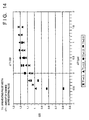
- Fig. 14 illustrates a change in OD value in a case where the preheating pulses are changed.
- the preheating pulses fluctuate by more than. 0.5 ⁇ sec from the usual value, depending upon the particular case, owing to the correction. For example, if a drive pulse which is equivalent to a single heating pulse is on the order of 4 ⁇ sec, a pulse which is approximately 15% longer than usual is applied to a printing element discharging ink which represents a low density. This has the effect of shortening the service life of the printhead. Further, when the change in a heating pulse is large, the change in the OD value also becomes very large, as shown in Fig. 14.
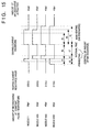
- an interval (referred to as a quiescent interval) in which heating pulses are not applied is provided between preheating and main heating of the printhead, as shown in Fig. 15, thereby changing the printing density.
- a quiescent interval in which heating pulses are not applied is provided between preheating and main heating of the printhead, as shown in Fig. 15, thereby changing the printing density.
- the width of the quiescent interval between a preheating pulse and a main heating pulse is adjusted along with the pulse widths of these pulses.
- the preheating pulses are selected on the board.
- the density correction may be performed by changing the width of the main heating pulses using a counter or the like.
- control unit on the side of the printing apparatus controls the printing operation of the printhead on the basis of correction data that has been stored in a memory within the printhead.
- control unit is provided within the printhead.
- an ink which is solid in a non-use state and liquefies upon heating may be used.
- an ink which liquefies upon application of heat energy according to a printing signal and is discharged in a liquid state, an ink which begins to solidify when it reaches a printing medium, or the like, is applicable to the present invention.
Description
- This invention relates to a method and apparatus for correcting a printhead, a printhead corrected by this apparatus, and a printing apparatus using this printhead. More particularly, the invention relates to a method and apparatus for correcting, by way of example, a full-line printhead equipped with a plurality of printing elements corresponding to the printing width of a recording medium, a printhead corrected by this apparatus, and a printing apparatus using this printhead.
- A printer or the printing section of a copying machine or facsimile machine is so adapted as to print an image, which comprises a dot pattern, on a recording medium such as a paper, a thin plastic sheet or fabric based upon image information.
- Among these printing apparatus, those which are the focus of attention because of their low cost are mounted with printheads that rely upon the ink-jet method, the thermosensitive-transfer method or the LED method, etc., in which a plurality of printing elements corresponding to dots are arrayed on a base.
- In a printhead in which these printing elements are arrayed to correspond to a certain printing width, the printing elements can be formed through a process similar to a semiconductor manufacturing process. Accordingly, a transition is now being made from a configuration in which the printhead and driving integrated circuitry are arranged separately of each other to an integrated assembled configuration in which the driving integrated circuitry is structurally integrated within the same base on which the printing elements are arrayed. As a result, complicated circuitry involved in driving the printhead can be avoided and the printing apparatus can be reduced in size and cost.
- Among these types of printing methods, the ink-jet printing method is particularly advantageous. Specifically, according to this method, thermal energy is made to act upon ink and the ink is discharged by utilizing the pressure produced by thermal expansion. This method is advantageous in that the response to a printing signal is good and it is easy to group the orifices close together at a high density. There are greater expectations for this method in comparison with the other methods.
- When the printhead is manufactured by applying a semiconductor manufacturing process and, in particular, when numerous printing elements that are to be made to correspond to the printing width are arrayed over the entire area of a base, it is very difficult to manufacture all of the printing elements without any defects. As a consequence, the manufacturing yield of the process for manufacturing the printhead is poor and this is accompanied by higher cost. There are occasions where such a printhead cannot be put into practical use because of the costs involved.
- Accordingly, methods of obtaining a full-line printhead have been disclosed in the specifications of Japanese Patent Application Laid-Open (KOKAI) Nos. 55-132253, 2-2009, 4-229278, 4-232749 and 5-24192 and in the specification of USP 5,016,023. According to these methods, a number of high-yield printheads each having an array of printing elements of a comparatively small number of orifices, e.g., 32, 48, 64 or 128 printing elements, are placed upon (or upon/below) a single base at a high precision in conformity with the density of the array of printing elements, thereby providing a full-line printhead whose length corresponds to the necessary printing width.
- It has recently become possible on the basis of this technique to simply manufacture a full-line printhead by arraying printing elements of a comparatively small number (e.g., 64 or 128) of orifices on bases, (also referred to as "printing units") and bonding these printing units in a row on a base plate in highly precise fashion over a length corresponding to the necessary printing width.
- Though it has thus become easy to manufacture a full-line printhead, certain performance-related problems remain with regard to a printhead manufactured by the foregoing manufacturing method. For example, a decline in printing quality, such as density unevenness, cannot be avoided. The cause is a variation in performance from one printing unit (base) to another in the row of such printing units, a variation in the performance of neighboring printing elements between the arrayed printing units and heat retained in each driving block at the time of recording.
- In particular, in the case of an ink-jet printhead, not only a variation in the neighboring printing elements between the arrayed printing units but also a decline in ink fluidity owing to the gaps between printing units results in lower yield in the final stage of the printhead manufacturing process. For this reason, the state of the art is such that these printheads are not readily available on the market in large quantities regardless of the fact these printheads exhibit highly satisfactory capabilities.
- EP-A-0421806 describes an image forming apparatus having a reader for reading correction data from a memory of a recording head and a device for controlling the image formation conditions in accordance with the correction data read from the recording head. EP-A-0452157 discloses a technique for generating correction data for correcting for density unevenness by detecting a printed density per recording element based on a printed test pattern and then generating correction data which is commonly applied to a plurality of adjacent image generating elements. EP-A-0605216 discloses a technique for measuring colour density on a plurality of test patterns by using an optical scanner. The performance of an image forming element is normalised by operating it at first and second test values and then calculating an optimum value from the results obtained at those first and second test values. EP-A-0670219 describes an ink jet printing apparatus wherein upon detection of a variation in density of the output of a printhead the average dot area produced by a printing element and the printing elements on either side of that printing element are calculated, averaged and the density unevenness defined using the average value.
- Accordingly, an object of the present invention is to provide an apparatus and method for correcting a manufactured printhead, wherein it is possible to realize a printhead at low cost and high yield without subjecting the printhead to a much load and without inviting a decline in printing quality, such as a decline in quality caused by visible density unevenness.
- According to one aspect of the present invention, there is provided a system as set out in
claim 1. - In an embodiment, the detecting means in the apparatus includes reading means for reading the recorded image, image processing means for processing an image signal representing the image read by the reading means, counting means for counting the number of black pixels or white pixels per the plurality of pixels from the image signal that has been subjected to image processing, and binarizing means for comparing the number of black pixels or white pixels obtained by the counting means with a predetermined threshold value, thereby binarizing the number of black pixels or white pixels, and the correction-data generating means generates the correction data based upon the binarized value.
- According to another aspect of the present invention, there is provided a method of producing a printhead having a corrected printing characteristic as set out in
claim 11. - In case of apparatus embodying the invention, a printhead having a plurality of printing elements and memory means capable of storing information is mounted to the apparatus, experimental printing is performed on a recording medium, a variation in density per a plurality of pixels selected upon considering human visual discriminating ability is detected from the image printed on the recording medium, correction data for correcting the detected variation in density is generated per the plurality of printing elements and this correction data is transmitted to the memory means possessed by the printhead.
- Thus, in case of apparatus embodying the invention, a printhead having a plurality of printing elements and memory means capable of storing information is mounted to the apparatus, experimental printing is performed on a recording medium, a variation in density per a plurality of pixels selected upon considering human visual discriminating ability is detected from the image printed on the recording medium, correction data for correcting the detected variation in density is generated per the plurality of printing elements and this correction data is transmitted to the memory means possessed by the printhead. As a result, the invention is particularly advantageous in that it is possible to correct, in simple fashion, a printhead at low cost and high yield without complicating the manufacturing process and without inviting a decline in printing quality, such as a decline in quality caused by visible density unevenness.
- In particular, in a case where a printhead having a very large number of printing elements and extending across the printing width of the recording medium is corrected, the invention is effective in that a variation in printing density ascribable to the printing elements is eliminated.
- A printing apparatus mounted with the printhead corrected as set forth above is such that the correction data that has been stored in the memory means of the printhead is received, a control signal is generated on the basis of the correction data to control the operation of the drive means, with which the printhead is provided, in such a manner that the plurality of printing elements of the printhead form uniform pixels, and the control signal is sent to the printhead. As a result, an advantage of the invention is that it is possible to perform high-quality printing without visible density unevenness.
- In an embodiment the control signal includes the first pulse signal and the second pulse signal that follows the first pulse signal, and the width of the first pulse signal, the width of the second pulse signal and the pulse interval between the first and second pulse signals are adjusted in the printing apparatus on the basis of the correction data received from the printhead. As a result, high-quality image printing is obtained without the application of long pulses that subjects the printhead to a heavy load. This contributes to extending a lifetime of the printhead.
- Other features and advantages of the present invention will be apparent from the following description taken in conjunction with the accompanying drawings, in which like reference characters designate the same or similar parts throughout the figures thereof.
- The accompanying drawings, which are incorporated in and constitute a part of the specification, illustrate embodiments of the invention and, together with the description, serve to explain the principles of the invention.
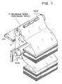
- Fig. 1 is a general view of a full-line ink-jet printer, which is a typical embodiment of the present invention;
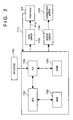
- Fig. 2 is a block diagram showing a control configuration for executing control of printing in the ink-jet printer;
- Fig. 3 is a block diagram showing the construction of a printhead correction apparatus according to this embodiment;
- Fig. 4 is a perspective view showing the construction of the printhead correction apparatus;
- Fig. 5 is a flowchart showing the operation of the printhead correction apparatus;
- Fig. 6 is a diagram illustrating a test pattern for correcting density using this embodiment;
- Fig. 7 is an exploded perspective view for describing the construction of a printhead according to the present invention;
- Fig. 8 is a detailed view showing heater boards arranged side by side;
- Figs. 9A, 9B, 9C and 9D illustrate the shape of a grooved member;
- Fig. 10 is a diagram showing the grooved member and heater boards in a fixed state;
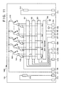
- Fig. 11 is a diagram showing an example of the circuit arrangement of a drive circuit provided on the heater board for the printhead;
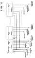
- Fig. 12 is a block diagram showing a multiple-nozzle head constituted by an array of a plurality of heater boards;
- Fig. 13 is a diagram showing an example of control of driving current waveforms for driving the printing elements;
- Fig. 14 is a diagram showing the relationship between an OD value and preheating pulses;
- Fig. 15 is a diagram showing driving current waveforms for driving the printing elements of this embodiment;
- Fig. 16 is a diagram showing the relationship between an OD value and interval time.
-
- Preferred embodiments of the present invention will now be described in detail with reference to the accompanying drawings.
- Fig. 1 is an external perspective view showing the principal portions of an ink-jet printer IJRA, which is a typical embodiment of the present invention. As shown in Fig. 1, the printer has a printhead (a full-length multiple printhead) IJH arranged along a range of full width of recording paper (a continuous sheet) P. The printhead IJH discharges ink over a range extending across the full width of the recording paper P. The ink is discharged toward the recording paper P from an orifice IT of the printhead at a prescribed timing.
- In this embodiment, the continuous sheet of foldable recording paper P is conveyed in the direction VS in Fig. 1 by driving a conveying motor under the control of a control circuit, described below. An image is printed on the recording paper. The printer in Fig. 1 further includes
sheet feeding rollers 5018 anddischarge rollers 5019. Thedischarge rollers 5019 cooperate with thesheet feeding rollers 5018 to hold the continuous sheet of recording paper P at the printing position and operate in association with thesheet feeding rollers 5018, which are driven by a drive motor (not shown), to feed the recording paper P in the direction of arrow VS. - Fig. 2 is a block diagram illustrating the construction of the control circuit of the ink-jet printer. Shown in Fig. 2 are an
interface 1700 for entering a printing signal from an external device such as a host computer, anMPU 1701, aROM 1702 for storing a control program (inclusive of character fonts as necessary) executed by theMPU 1701, aDRAM 1703 for temporarily saving various data (the above-mentioned printing signal and printing data that is supplied to the printhead), and a gate array (G.A.) 1704 for controlling supply of printing data to the printhead IJH. Thegate array 1704 also controls transfer of data among theinterface 1700,MPU 1701 andRAM 1703. Also shown are aconveyance motor 1708 for conveying recording paper (the continuous sheet in this embodiment), ahead driver 1705 for driving the printhead, and amotor driver 1706 for driving theconveyance motor 1708. - As for the general operation of the above-mentioned control circuit, the printing signal enters the
interface 1700, whereupon the printing signal is converted to printing data for printing between thegate array 1704 andMPU 1701. Themotor driver 1706 is driven into operation and the printhead IJH is driven in accordance with the printing data sent to thehead driver 1705. As a result, a printing operation is carried out. -
Numeral 1711 denotes a signal line for monitoring sensors (e.g., a heating-resistor sensor 314 and atemperature sensor 315, which are shown in Fig. 11) of each board, and for transmitting correction data from a memory 13 (described later) storing correction data which corrects for a variation in each board (heater board 1000, described later) provided within the printhead IJH.Numeral 1712 denotes a signal line for carrying preheating pulses, latch signals and heating pulses. On the basis of the correction data from thememory 13 in the printhead IJH, theMPU 1701 sends the printhead IJH a control signal via thesignal line 1712 in such a manner that the boards are capable of forming uniform pixels. - Fig. 3 is a block diagram illustrating the construction of the printhead correction apparatus of this embodiment. An I/
O interface 2 interfaces theCPU 1 with the various controllers of the apparatus. Animage processor 3 uses aCCD camera 4 to read the printing dot pattern on a recording medium placed upon apaper feeding stage 5 and converts the dot diameter and density unevenness of the dot pattern to pixel values. When the dot data corresponding to all printing elements of the printhead IJH is sent from theimage processor 3 to theCPU 1, the latter operates upon the dot data, sends density correction data to adriving signal controller 7 in conformity with a drive signal for driving the printhead IJH and causes amemory controller 8 to develop the density correction data. - An
image data controller 6 outputs a dot pattern to be recorded to the printhead IJH. Thecontroller 6 transmits a density correction drive signal while sending a synchronizing signal to thedrive signal controller 7 not only at the time of ordinary printing but also when the density correction data has been determined. TheCPU 1 manages ahead voltage controller 9 which controls the driving voltage of the printhead IJH and manages a stage/paper-feed controller 11 for controlling the operation of thepaper feeding stage 5, thereby setting a proper drive voltage and controlling stage movement and paper feed. Furthermore, ahead data detector 10 is an important component which feeds back, for the purpose of density correction, the characteristics of each board (printing unit) 1000 (see Fig. 7) within the printhead IJH. - In the printhead IJH which, by way of example, is composed of a row of a
plurality boards 1000 on which 64 or 128 printing elements have been disposed, it is not known from which portions of a silicon wafer or the like theboards 1000 have been cut. Accordingly, there are cases in which the characteristics differ from one board to another. - In such case, a rank detecting resistor element RH having a surface resistivity (Ω/□) identical with that of the printing element is provided in each
board 1000 in order that all printheads can perform printing at an uniform density. There are also cases in which a semiconductor element capable of monitoring a change in temperature is provided for eachboard 1000. Thehead data detector 10 monitors these elements. When thehead data detector 10 sends data obtained by monitoring these elements to theCPU 1, the latter generates correction data, which is for correcting the data that drives each of theboards 1000, in such a manner that eachboard 1000 in the printhead can print at a uniform density. The rank mentioned here is a parameter obtained by quantifying the characteristic of eachboard 1000. The parameter is expressed by a function of a surface resistivity (Ω/□). - When the above-mentioned correction data is reflected in each controller of the printhead correction apparatus, the printing operation by the printhead IJH is executed under these conditions. In the correcting apparatus, the results of printing are again subjected to image processing by the
CCD camera 4 andimage processor 3, and thememory controller 8 writes the final correction data in the memory 13 (a non-volatile memory such as an EEPROM) at a stage at which the predetermined criteria of the printhead is satisfied. - Fig. 4 is an external perspective view showing the construction the printhead correction apparatus, and Fig. 5 is a flowchart illustrating the operation of the apparatus. Operation will now be described with reference to Figs. 4 and 5.
- When the printhead IJH is inserted into a slot of a securing table 50, the
CPU 1 operates the table 50 and fixes the printhead IJH to the table 50 in such a manner that the printhead IJH can perform printing at a normal position. At the same time, electrical contact is made with the printhead IJH, and anink supply device 52 is connected to the printhead IJH (step S2). Next, in order to measure the rank of the printhead IJH, the a surface resistivity (Ω/□) of thesubstrate 1000 is monitored (step S4). - In the case of a full-line printhead unit, the a surface resistivity (Ω/□) of each block (of each board in a case where the block is constituted by an array of a plurality of boards) is monitored, driving power is decided separately for each board and a test pattern is recorded (step S6). As preprocessing for printing the test pattern, preliminary discharge (aging) is carried out until the operation of the printhead IJH stabilizes to enable stable printing by the printhead. Aging is performed on an aging tray juxtaposed on a
head recovery processor 54, and recovery processing (ink suction, cleaning of orifice surfaces, etc.) is executed in such a manner that the test pattern can be printed normally. When a test pattern is thus printed, the result of printing is moved to the position of theCCD camera 4 and of theimage processor 3, where the result of printing is subjected to image processing by these components and compared with parameters for printing evaluation. Processing is executed while taking the items mentioned below into account in relation to density unevenness of recording elements. Density unevenness is a parameter that can be improved. - Density unevenness of an image is produced by a difference in relative density contrast in printing performed by printing elements. The smaller the contrast, the less noticeable density unevenness is to the eye. When printing elements which produce a high-density printing are concentrated somewhat closely together in space, the occurrence of density unevenness becomes apparent.
- When the limit on visual discriminating ability is put into the form of a formula from the viewpoint of density unevenness, the following relation is obtained from experiment:
- When the discriminating limit of the human eye with respect to density unevenness in an image is taken into account, density unevenness data near the discriminating ability of the human eye can be created by (1) performing a density unevenness correction in units of several dots (two to eight pixels, depending upon printing density); and (2) increasing the number of events of image processing (the number of events per printed dot or the number of events in a group of printed dots (16 ~ 1024 dots)).
- A procedure for creating such density unevenness data will now be described in detail.
- Fig. 6 illustrates an example of an image pattern read by a CCD camera or the like. In Fig. 6, a dot pattern having a 50% duty is formed and a dot pattern of 32 dots x 32 dots is allocated to the screen area of the CCD camera. In Fig. 6, A and B are areas of 4 × 32 dots each. In this embodiment, each are a is one event. Further, C and D in Fig. 6 are disposed as markers for image recognition of the dot pattern of 32 × 32 dots.
- Let n represent the first dot read. The area A constituting one event is composed of a collection of 32 bits in the y direction (the direction in which the recording medium is conveyed) from n to n+3 in the x direction (the column direction of the printing elements). Eight similar areas are produced in an image memory (not shown), and binarizing processing is performed in each area in accordance with the number of "black" or "white" pixels in the area and a predetermined threshold value. It should be noted that an optimum value obtained experimentally is used as the threshold value. As the result of this binarizing processing, density unevenness data is obtained for every four dots in the x direction.
- Further, adopting the absolute density (the total number of black pixels) in each area as the density unevenness data also is effective.
- Furthermore, an image having an area corresponding to more than 100 dots per one nozzle of a printing element can be read in and processed by an image scanner, wherein the dot pattern has the 50% duty shown in Fig. 6, and the processed results can be used as the density unevenness data.
- Since an event number of more than 100 dots (100 printing operations) per nozzle is obtained with this method, a subtle fluctuation in dot diameter in relation to the y direction is averaged. When density unevenness is discriminated by the human eye, the fluctuation in the y direction is not very noticeable. However, when the number of events is small, the density unevenness does not become a density unevenness that can be visually recognized by the human eye and is not appropriate as density unevenness data. The reason is that the data does not become statistical data that is meaningful to the extent that it can be visually discerned by the human eye. If density unevenness data in dot units is obtained in the x direction, several dots of the data can be collected and adopted as density unevenness data. In this case an arrangement may be adopted in which it is possible to externally set the number of dot units. In order to create correction data in units of four dots, as mentioned above, the density unevenness data in units of four dots in the x direction may be averaged.
- The density unevenness data thus obtained does not have a complicated structure and can be processed in a short period of time in both a printhead manufacturing apparatus and a printer.
- With regard to the density unevenness data every four dots obtained as described above, the same data is provided for every four nozzles of the printing.
- When density unevenness data is thus obtained, how each element is to be corrected is decided based upon this data. For example, in a case where the driving power of each recording element of the printhead is decided by pulse width, driving pulse-width data applied to an integrated circuit for driving the printhead is selected. As will be described later, in a case where the pulse-width control circuit of the driving integrated circuit makes a selection from several pulse widths, the MAX, MIN of the pulse width selected are decided and a pulse width between these values is set based upon the resolution allowed. The pulse width is set so as to correct the printing density of each element in conformity with the image processing data, and the pulse width is made to correspond to each printing element, whereby it is possible to average the printing densities of the printhead unit. The foregoing is repeated until the above-described processing is finished. When this occurs, the resulting data is stored in the
memory 13. This processing is carried out at steps S8 ~ S12 in Fig. 5. - Note that this embodiments can reduce the number of testing performed until it is determined at step S8 that the testing is OK, compared to U.S. Patent Application No. 08/397,352 filed on March 2, 1995.
- U.S. Patent Application No. 08/397,352 (Japanese Patent Application No. 6-34558) discloses a method of correcting the unevenness in the density of a printhead by measuring dot diameter and correcting unevenness based upon the results of measurement. However, it is still necessary to improve reproducibility of printed dots. For example, when one line of printing has been performed, the characteristics of the printed dots change subtly on the next line, over then next several dozen lines and over the next several hundred lines. (This is known as "fluctuation" from dot to dot.) Since a specific phenomenon (dot diameter) which incorporates this fluctuation is employed as information regarding density unevenness, satisfactory results are not obtained with a single correction. In order to acquire the desired image quality, it is required that printed dot data from several measurements be acquired to perform the correction. In a case where electrical energy is converted to thermal energy in conformity with correction data, energy which is larger than usual is applied to the printing elements that exhibit a low density. Thus, it is highly desirable to further improve reliability in terms of the durability of the printhead.
- Fig. 7 is an exploded perspective view for describing the construction of the printhead of this embodiment. In this example, a case is described in which the printing elements are elements for generating ink-discharge energy used to jet ink. (In a bubble-jet printing method, each element comprises a pair of electrodes and a heating resistor element provided between these electrodes).
- In accordance with the method described below, the full-line printhead, which is faultlessly fabricated over its entire width by a conventional photolithographic process or the like, is obtained at a very high yield. Moreover, a single, unitary grooved member having a plurality of ink discharge orifices formed in one end and a plurality of grooves connected to these orifices and formed in the grooved member from one end to the other is joined to this printhead in such a manner that the grooves are closed by the boards, whereby a full-line, ink-jet printhead unit can be corrected in a very simple manner.
- The ink-jet printhead described in this embodiment has ink discharge orifices at a density of 360 dpi (70.5 µm), the number of nozzles thereof being 3008 (for a printing width of 212 mm).
- In Fig. 7, the board (hereinafter referred to as a heater board) 1000 has 128 discharge-
energy generating devices 1010 arranged at prescribed positions at a density of 360 dpi. Eachheater board 1000 is provided with a signal pad to drive the discharge-energy generating devices 1010 at any timing by externally applied electric signals, and with apower pad 1020 for supplying an electric power for the driving. - The row of the
heater boards 1000 is fixedly bonded by a bonding agent to the surface of abase plate 3000 made of a material such as metal or ceramic. - Fig. 8 is a detailed view showing the
heater boards 1000 in the arrayed state. The heater boards are fixedly bonded to a prescribed location on thebase plate 3000 by abonding agent 3010 applied to a prescribed thickness. At this time eachheater board 1000 is fixedly bonded in precise fashion in such a manner that the spacing or pitch between the discharge-energy generating devices 1010 situated at the respective edges of two mutually adjacent heater boards will be equal to the spacing or pitch P (= 70.5 µm) of the discharge-energy generating devices 1010 on eachheater board 1000. Further, the gaps produced betweenadjacent heater boards 1000 are filled and sealed by asealant 3020. - With reference again to Fig. 7, a
wiring board 4000 is fixedly bonded to thebase plate 3000 in the same manner as the heater boards. At this time thewiring board 4000 is bonded to thebase plate 3000 in a state in which thepads 1020 on theheater boards 1000 are in close proximity to signal-power supply pads 4010 provided on thewiring board 4000. Aconnector 4020 for receiving a printing signal and driving power from the outside is provided on thewiring board 4000. - A
grooved member 2000 will now be described. - Figs. 9A ~ 9D are diagrams showing the shape of the
grooved member 2000. Fig. 9A is a front view in which thegrooved member 2000 is seen from the front, Fig. 9B a top view in which Fig. 9A is seen from the top, Fig. 9C a bottom view in which Fig. 9A is seen from the bottom, and Fig. 9D a sectional view taken along line X-X of Fig. 9A. - In Figs. 9A ~ 9D, the
grooved member 2000 is shown to have aflow path 2020 provided to correspond to each discharge-energy generating element 1010 provided in theheater board 1000, anorifice 2030 corresponding to eachflow path 2020 and communicating with theflow path 2020 for discharging ink toward the recording medium, aliquid chamber 2010 communicating with eachflow path 2020 in order to supply it with ink, and anink supply port 2040 for feeding ink, which has been supplied from an ink tank (not shown), to theliquid chamber 2010. Thegrooved member 2000 naturally is formed to have a length large enough to substantially cover the row of discharge-energy generating devices arranged by lining up a plurality of theheater boards 1000. - With reference again to Fig. 7, the
grooved member 2000 is joined to theheater boards 1000 in a state in which the positions of theflow path 2020 of thegrooved member 2000 are made to exactly coincide with the positions of the discharge-energy generating elements (heaters) 1010 on theheater boards 1000 arranged in a row on thebase plate 3000. - Conceivable methods of joining the
grooved member 2000 are a method in which the grooved member is pushed in mechanically using springs or the like, a method in which thegrooved member 2000 is fixed by a bonding agent, and a method which is a combination of these methods. - The
grooved member 2000 and each of theheater boards 1000 are secured in the relationship shown in Fig. 10 by any of these methods. - The
grooved member 2000 described above can be manufactured using well-known methods such as machining by cutting, a molding method, casting or a method relying upon photolithography. - Fig. 11 shows an example of drive circuitry provided on the
heater board 1000 of the printhead.Numeral 100 denotes a base, 101 a logic block for selecting preheating pulses, 303 a latch for temporarily storing image data, 102 a selection-data saving latch, having the same circuit arrangement as thelatch 303, for selecting preheating pulses, and 103 an OR gate for taking the OR of heating pulses and preheating pulses. - The operation of this drive circuitry will now be described in line with a driving sequence.
- After power is introduced from a
logic power source 309, preheating pulses are selected dependence upon the characteristic of the amount of ink discharged (per application of a pulse at a fixed temperature). The characteristic is measured in advance. Data of each nozzle (the data is identical for four nozzles) for selecting the preheating pulses in dependence upon the aforesaid characteristic is saved in the selection-data saving latch 102 using ashift register 304 for entering image data serially. Since shared use is made of theshift register 304 for entering image data, it will suffice merely to increase the number of latch circuits and latch the outputs of theshift register 304 as input signals in parallel fashion, as shown at points a in Fig. 11. This makes it possible to prevent an increase in the surface area of the elements other than that of the latch circuits. Further, in a case where the number of preheating pulses is increased and the number of bits necessary for selection of the number of pulses surpasses the number of bits of theshift register 304, this can readily be dealt with if thelatch 102 is made plural in number and a latch-clock input terminal 108 which decides latching is made plural in number, as shown at 108a ~ 108h. It will suffice if the saving of data for selection of the preheating pulses is performed one time, such as when the printer is started up. The image-data transfer sequence will be performed exactly the same as conventionally even if this function is incorporated. Furthermore, an arrangement may be adopted in which the number of bits inlogic block 101 and in the selection-data saving latch 102 is made one-fourth, the preheating pulses are selected in units of four nozzles and are supplied in units of four nozzles. - Entry of heating signals will now be described as a sequence with follows completion of the storing of saved data, representing the amount of ink discharge, for selection of preheating pulses.
- A characterizing feature of this board is that a
heating input terminal 106 and a plurality of preheatinginput terminals 107a ~ 107h, which are used for changing the amount of ink discharged, are separately provided. First, a signal from the heating-resistor monitor 314 is fed back and a heating signal having a pulse width of an energy suited to discharge of ink in dependence upon the value of feedback is applied to theheating input terminal 106 from the side of the printing apparatus. Next, the pulse width and timing of each of the plurality of preheating signals are changed in dependence upon the value from thetemperature sensor 315 and, at the same time, preheating signals are applied from the plurality of preheatingpulse terminals 107a ~ 107h in such a manner that the amount of ink discharged will vary under fixed temperature conditions. Thus, if a selection is made to deal with a factor other than temperature, namely a change in the amount of ink discharge of each nozzle, the amount of ink discharge can be rendered constant to eliminate unevenness and blurring. One of the plurality of preheating pulses thus entered is selected in dependence upon selection data saved in advance in the preheat selection logic block (latch) 102. Next, an AND signal between the image data and heating signal is OR-ed with a selected preheating pulse by theOR gate 103, and the resulting signal drives apower transistor 302, thereby passing an electric current through theheater 1010 to discharge ink. - Shown in Fig. 11 are an input
signal input terminal 104, aclock input terminal 105, a latchsignal input terminal 307, aground terminal 310, a power-supplyvoltage input terminal 311 for heating purposes, anoutput terminal 312 for heating-resistor monitoring data, and anoutput terminal 313 for data indicating the temperature inside the printhead. - Reference will be had to Fig. 12 to describe the construction of a multiple-nozzle head constituted by a plurality of the
heater boards 1000 arranged in a row. There are m-number of boards in the row and a total of n-number of nozzles. The description will focus onnozzles board 1 andnozzle 150 ofboard 2. - As shown in Fig. 13, assume that the amounts of ink discharged by
nozzles nozzle 1 than fornozzles resistance sensors board 1 and that 210 Ω is the heating-resistance value ofboard 2, as shown in Fig. 13, the pulse width applied toboard 2 is made larger than that applied toboard 1 so that the introduced power will be rendered uniform. Fig. 13 illustrates driving current waveforms applied under these conditions. It will be understood that the preheating pulse ofnozzle 1 which discharges a small amount of ink has a pulse width larger than that of the preheating pulses fornozzles 100 and 150 (t1<t2). Further, the heating pulse width t4 is larger than t3 (t4>t3). In Fig. 13, t5 represents the pulse width for minimum power needed to foam the ink and cause the ink droplets to be discharged from the nozzles. The following relationships hold: t1, t2<t5 and t3, t4>t5. - Thus, the preheating pulses are changed under conditions in which the relations t1<t2; t1, t2<t5 hold with respect to a change in the temperature of the board during drive. As a result, the amount of ink discharged from each nozzle during actual drive can be made 40 pl at all times. This makes it possible to achieve high-quality printing without unevenness and blurring.
- Furthermore, with regard to the heating pulses exhibiting a high power, the pulse width is adjusted in dependence upon the resistance value of the board, whereby a constant power is applied without waste. This contributes to a longer service life for the printhead.
- Fig. 14 illustrates a change in OD value in a case where the preheating pulses are changed.
- In a case where there is a very large density unevenness between nozzles (e.g., a case where the amount of ink discharge of
nozzle 200 at a constant pulse width and temperature is 32 pl, which is 20% less than the amount of ink discharge ofnozzles - Accordingly, in this embodiment, an interval (referred to as a quiescent interval) in which heating pulses are not applied is provided between preheating and main heating of the printhead, as shown in Fig. 15, thereby changing the printing density. As a result, there is no shortening in the life of the printhead.
- Fig. 16 illustrates a change in the OD value in a case where the preheating pulse width and main heating pulse width are fixed and the quiescent interval is changed.
- As a result, if emphasis is placed upon a change in the quiescent interval and a printed dot which cannot be corrected within the range of this change is corrected utilizing the preheating pulses as well, then a large change in energy need not be applied to the printing elements of the printhead, the life of the printhead can be extended and the quality of a printing image can be improved.
- In this embodiment, the application of drive pulses differs from that shown in Fig. 13 with regard particularly to
nozzle 1 andnozzle 200, as shown in Fig. 15. With regard tonozzle 1, density is somewhat lower in comparison withnozzles 100 and 150 (the amount of reduction in ink discharge is 10%). Therefore, the quiescent interval is made slightly longer (t6) in comparison with that (t7) fornozzles nozzle 200, there is a very large difference in density in comparison withnozzles 100 and 150 (the amount of reduction in ink discharge is 20%). Therefore, while the interval time is lengthened (t6), the preheating pulse width is stretched (t2) in comparison with the heating pulse width (t1) ofnozzles - Thus, in accordance with the present invention, the dots of prescribed pattern data, which have been printed by a printhead, are gathered together in a prescribed plurality of areas per each nozzle (recording element) of the printhead upon taking into account the visual discriminating ability of the human eye, and information obtained from the plurality of areas can be applied as density unevenness data. As a result, a variation in dot-to-dot diameter which exceeds the visual discriminating ability of the human eye is no longer discerned as density unevenness. In comparison with a case in which the dot diameter of each dot is discerned as density unevenness, information capable of accurate density correction can be supplied more rapidly for each printing element. As a result, it is possible to perform more rapid entry of fine correction data adapted to each printing element in the final stage of the printhead manufacturing process.
- Furthermore, in a case where the amount of ink per printing operation discharged from each nozzle of the printhead is adjusted using the correction data obtained, the width of the quiescent interval between a preheating pulse and a main heating pulse is adjusted along with the pulse widths of these pulses. As a result, even if the amount of ink discharge fluctuates widely between nozzles under conditions of a constant pulse width or constant temperature, control can be performed so as to equalize the amount of ink discharge from one nozzle to the next without lengthening pulse width to such an extent that the printhead will be subjected to an abnormally large load. This makes it possible to prolong the life of the printhead while attaining a high image quality.
- In the description set forth above, it is mentioned that the preheating pulses are selected on the board. However, this does not impose a limitation upon the invention. For example, the density correction may be performed by changing the width of the main heating pulses using a counter or the like.
- Furthermore, it goes without saying that the present invention may be applied to effect a density correction if the board is such that control of the driving power of each printing element is possible. The same density correction can be performed even if the printhead has a construction different from that described.
- In the description given above, it is described that the control unit on the side of the printing apparatus controls the printing operation of the printhead on the basis of correction data that has been stored in a memory within the printhead. However, an arrangement may be adopted in which such a control unit is provided within the printhead.
- Though a full-line printer has been taken as an example in the description given above, the invention is not limited to such a printer. For example, in a serial printer of the type in which printing is performed by moving a printhead mounted on a carriage, the invention is applicable to an arrangement in which the printing is carried out by a number of nozzles arrayed in a row in the direction in which the recording paper is conveyed. Also, this invention is applicable to another type of printhead such as an ink jet printhead, thermal printhead or LED printhead.
- It goes without saying that equivalent effects are obtained even if there is a difference in the method of setting the driving power of each of the recording elements of the printhead.
- Each of the embodiments described above has exemplified a printer, which comprises means (e.g., an electrothermal transducer, laser beam generator, and the like) for generating heat energy as energy utilized upon execution of ink discharge, and causes a change in state of an ink by the heat energy, among the ink-jet printers. According to this ink-jet printer and printing method, a high-density, high-precision printing operation can be attained.
- As the typical arrangement and principle of the ink-jet printing system, one practiced by use of the basic principle disclosed in, for example, U.S. Patent Nos. 4,723,129 and 4,740,796 is preferable. The above system is applicable to either one of so-called an on-demand type and a continuous type. Particularly, in the case of the on-demand type, the system is effective because, by applying at least one driving signal, which corresponds to printing information and gives a rapid temperature rise exceeding film boiling, to each of electrothermal transducers arranged in correspondence with a sheet or liquid channels holding a liquid (ink), heat energy is generated by the electrothermal transducer to effect film boiling on the heat acting surface of the printhead, and consequently, a bubble can be formed in the liquid (ink) in one-to-one correspondence with the driving signal. By discharging the liquid (ink) through a discharge opening by growth and shrinkage of the bubble, at least one droplet is formed. If the driving signal is applied as a pulse signal, the growth and shrinkage of the bubble can be attained instantly and adequately to achieve discharge of the liquid (ink) with the particularly high response characteristics.
- As the pulse driving signal, signals disclosed in U.S. Patent Nos. 4,463,359 and 4,345,262 are suitable. Note that further excellent printing can be performed by using the conditions described in U.S. Patent No. 4,313,124 of the invention which relates to the temperature rise rate of the heat acting surface.
- As an arrangement of the printhead, in addition to the arrangement as a combination of discharge nozzles, liquid channels, and electrothermal transducers (linear liquid channels or right angle liquid channels) as disclosed in the above specifications, the arrangement using U.S. Patent Nos. 4,558,333 and 4,459,600, which disclose the arrangement having a heat acting portion arranged in a flexed region is also included in the present invention. In addition, the present invention can be effectively applied to an arrangement based on Japanese Patent Laid-Open No. 59-123670 which discloses the arrangement using a slot common to a plurality of electrothermal transducers as a discharge portion of the electrothermal transducers, or Japanese Patent Laid-Open No. 59-138461 which discloses the arrangement having an opening for absorbing a pressure wave of heat energy in correspondence with a discharge portion.
- Furthermore, as a full line type printhead having a length corresponding to the width of a maximum printing medium which can be printed by the printer, either the arrangement which satisfies the full-line length by combining a plurality of printheads as disclosed in the above specification or the arrangement as a single printhead obtained by forming printheads integrally can be used.
- In addition, not only an exchangeable chip type printhead, which can be electrically connected to the apparatus main unit and can receive an ink from the apparatus main unit upon being mounted on the apparatus main unit but also a cartridge type printhead in which an ink tank is integrally arranged on the printhead itself can be applicable to the present invention.
- It is preferable to add recovery means for the printhead, preliminary auxiliary means, and the like provided as an arrangement of the printer of the present invention since the printing operation can be further stabilized. Examples of such means include, for the printhead, capping means, cleaning means, pressurization or suction means, and preliminary heating means using electrothermal transducers, another heating element, or a combination thereof. It is also effective for stable printing to provide a preliminary discharge mode which performs discharge independently of printing.
- Furthermore, as a printing mode of the printer, not only a printing mode using only a primary color such as black or the like, but also at least one of a multicolor mode using a plurality of different colors or a full-color mode achieved by color mixing can be implemented in the printer either by using an integrated printhead or by combining a plurality of printheads.
- Moreover, in each of the above-mentioned embodiments of the present invention, it is assumed that the ink is a liquid. Alternatively, the present invention may employ an ink which is solid at room temperature or less and softens or liquefies at room temperature, or an ink which liquefies upon application of a use printing signal, since it is a general practice to perform temperature control of the ink itself within a range from 30°C to 70°C in the ink-jet system, so that the ink viscosity can fall within a stable discharge range.
- In addition, in order to prevent a temperature rise caused by heat energy by positively utilizing it as energy for causing a change in state of the ink from a solid state to a liquid state, or to prevent evaporation of the ink, an ink which is solid in a non-use state and liquefies upon heating may be used. In any case, an ink which liquefies upon application of heat energy according to a printing signal and is discharged in a liquid state, an ink which begins to solidify when it reaches a printing medium, or the like, is applicable to the present invention. In this case, an ink may be situated opposite electrothermal transducers while being held in a liquid or solid state in recess portions of a porous sheet or through holes, as described in Japanese Patent Laid-Open No. 54-56847 or 60-71260. In the present invention, the above-mentioned film boiling system is most effective for the above-mentioned inks.
- In addition, the ink-jet printer of the present invention may be used in the form of a copying machine combined with a reader, and the like, or a facsimile apparatus having a transmission/reception function in addition to an image output terminal of an information processing equipment such as a computer.
- The present invention can be applied to a system constituted by a plurality of devices, or to an apparatus comprising a single device.
- As many apparently widely different embodiments of the present invention can be made, it is to be understood that the invention is not limited to the specific embodiments thereof except as defined in the appended claims.
Claims (17)
- A system for correcting a printing characteristic of a printhead (IJH), comprising:characterized in thata printhead (IJH) having an array of printing elements (1010) and memory means (13) for storing data;printhead drive means (6, 7, 9) for driving the printhead in accordance with test print data to produce on a recording medium a test print consisting of an array of recording pixels in each of which a dot is either printed or is not printed dependent on the test print data;detecting means (3, 4) for detecting a variation in print density in a test print printed on the recording medium;correction-data generating means (1) for generating for the printing elements correction data for correcting for the variation in density detected by said detecting means; andwriting means (8) for writing the correction data into the memory means of the printhead,
said detecting means is arranged to detect the print density at a resolution which is lower than 300dpi and which is lower than the resolution of the test print and equivalent to a group of adjacent recording pixels wherein each group consists of a matrix of recording pixels having N recording pixels in the matrix direction in which the printing elements are arrayed and M recording pixels in the other matrix direction where N and M are integers and 2≤N≤8 and 16≤M≤1024 such that a single density value is determined for each pixel group and to determine the variation between density values for different pixel groups whereby the density variation is determined at a resolution lower than the printing resolution of the printhead. - A system according to claim 1, further comprising control means for causing said printhead drive means (6, 7, 9), said detecting means (3, 4) and said correction-data generating means (1) to repeat the operations of causing the printhead to produce a test print using print drive data which reflects correction data produced using a previous test print, detecting any variation in density in said test print and generating correction data until the density is made uniform.
- A system according to claim 2, wherein said writing means (8) is arranged to write correction data into the memory means (13) of a printhead after the density has been made uniform.
- A system according to claim 1, 2 or 3, further comprising conveyance means (1708) for conveying the recording medium in a predetermined direction.
- A system according to claim 1, 2, 3 or 4, further comprising preliminary discharge means (1705) for causing the printhead to discharge printing material to stabilize the printing operation of the printhead before a test print is produced by the printhead.
- A system according to any one of the preceding claims, wherein said printhead drive means (6, 7, 9) is arranged to cause the printhead to generate a prescribed printing pattern as the test print.
- A system according to any one of claims 1 to 6, wherein said detecting means (3, 4) has counting means for counting the number of black pixels, that is pixels in which printing of a dot occurs, or the number of white pixels, that is pixels in which printing does not occur, binarizing means for generating a binary value by comparing the number of black or white pixels obtained by said counting means with a predetermined threshold value, and wherein said correction-data generating means (1) is arranged to generate the correction data based upon the counted number of black or white pixels.
- A system according to any one of the preceding claims, wherein said printhead drive means (6, 7, 9) is operable to cause dots having a 50% duty to be formed in a predetermined area of the image.
- A system according to any one of the preceding claims wherein said detecting means (3, 4) is arranged to detect a variation in density between pixel groups containing at least four successive recording pixels.
- A system according to claim 1, wherein the printing elements are arrayed at a resolution of 360 dpi, N is equal to 4 and M is equal to 32.
- A method of producing a printhead having a corrected printing characteristic, said method comprising the steps of:characterized by carrying out the detecting step by detecting the print density at a resolution which is lower than 300dpi and which is lower than the resolution of the test print and equivalent to a group of adjacent recording pixels wherein each group consists of a matrix of recording pixels having N recording pixels in the matrix direction in which the printing elements are arrayed and M recording pixels in the other matrix direction where N and M are integers and 2≤N≤8 and 16≤M≤1024 to determine single density value for each pixel group and determining the variation between density values for different pixel groups such that the density variation is determined at a resolution lower than the printing resolution of the printhead.driving a printhead having an array of printing elements (1010) and memory means (13) for storing data in accordance with test print data to produce on a recording medium a test print consisting of an array of recording pixels in each of which a dot is either printed or is not printed dependent on the test print data;detecting a variation in print density in the test print;generating for the printing elements correction data for correcting for the variation in density detected by said detecting means; andwriting the correction data into the memory means of the printhead;
- A method according to claim 11, further comprising a control step of repeating the printhead driving, detecting and correction-data generating steps until the detected print density is uniform.
- A method according to claim 12, which further comprises writing the correction data into the memory unit after the density has been made uniform.
- A method according to claim 11, 12 or 13, further comprising the step of causing the printhead to effect a preliminary discharge of printing material in order to stabilize the printing operation of the printhead before the test print is produced.
- A method according to claim 11, 12, 13 or 14, wherein said detecting step has a counting step of counting the number of black pixels, that is the pixels in which a dot is printed, or white pixels, that is the pixels in which no printing occurs, in a pixel group, generating a binary value by comparing the number of black or white pixels obtained in said counting step with a predetermined threshold value, and the correction data is generated based on the number of black or white pixels counted in said correction-data generating step.
- A method according to any one of claims 11 to 15, wherein said detecting step detects the variation in density using a pixel group consisting of at least four successive recording pixels.
- A printhead correction apparatus for use in a system in accordance with claim 1 for correcting a printing characteristic of a printhead (IJH) having an array of printing elements (1010) and memory means (13) for storing data, the apparatus comprising:characterized in thatprinthead drive means (6, 7, 9) for driving the printhead in accordance with test print data to produce on a recording medium a test print consisting of an array of recording pixels in each of which a dot is either printed or is not printed dependent on the test print data;detecting means (3, 4) for detecting a variation in print density in a test print printed on the recording medium;correction-data generating means (1) for generating for the printing elements correction data for correcting for the variation in density detected by said detecting means; andwriting means (8) for writing the correction data into the memory means of the printhead,
said detecting means is arranged to detect the print density at a resolution which is lower than 300dpi and which is lower than the resolution of the test print and equivalent to a group of adjacent recording pixels wherein each group consists of a matrix of recording pixels having N recording pixels in the matrix direction in which the printing elements are arrayed and M recording pixels in the other matrix direction where N and M are integers and 2≤N≤8 and 16≤M≤1024 such that a single density value is determined for each pixel group and to determine the variation between density values for different pixel groups whereby the density variation is determined at a resolution lower than the printing resolution of the printhead.
Applications Claiming Priority (3)
| Application Number | Priority Date | Filing Date | Title |
|---|---|---|---|
| JP26544494 | 1994-10-28 | ||
| JP26544494A JPH08118727A (en) | 1994-10-28 | 1994-10-28 | Method and apparatus for correcting recorder head, recording head corrected by the same apparatus and recorder using the same head |
| JP265444/94 | 1994-10-28 |
Publications (3)
| Publication Number | Publication Date |
|---|---|
| EP0709192A2 EP0709192A2 (en) | 1996-05-01 |
| EP0709192A3 EP0709192A3 (en) | 1996-07-31 |
| EP0709192B1 true EP0709192B1 (en) | 2002-02-06 |
Family
ID=17417243
Family Applications (1)
| Application Number | Title | Priority Date | Filing Date |
|---|---|---|---|
| EP95307600A Expired - Lifetime EP0709192B1 (en) | 1994-10-28 | 1995-10-25 | Method and apparatus for correcting printhead, printhead corrected by this apparatus, and printing apparatus using this printhead |
Country Status (4)
| Country | Link |
|---|---|
| US (1) | US6042213A (en) |
| EP (1) | EP0709192B1 (en) |
| JP (1) | JPH08118727A (en) |
| DE (1) | DE69525303T2 (en) |
Families Citing this family (46)
| Publication number | Priority date | Publication date | Assignee | Title |
|---|---|---|---|---|
| JP2963072B2 (en) * | 1996-09-30 | 1999-10-12 | キヤノン株式会社 | INK JET RECORDING METHOD AND DEVICE, COLOR FILTER, DISPLAY DEVICE, AND DEVICE WITH THE DISPLAY DEVICE |
| US6164746A (en) * | 1993-09-24 | 2000-12-26 | Canon Kabushiki Kaisha | Ink-jet printer method and apparatus, color filter, display device, apparatus having display device, ink-jet head unit adjusting device and method, and ink-jet head unit |
| JP3337912B2 (en) * | 1996-06-28 | 2002-10-28 | キヤノン株式会社 | Driving method of inkjet head and inkjet apparatus for executing the same |
| US6382756B1 (en) * | 1996-07-31 | 2002-05-07 | Canon Kabushiki Kaisha | Recording head and recording method |
| US6582048B1 (en) | 1996-09-30 | 2003-06-24 | Canon Kabushiki Kaisha | Ink-jet print method and apparatus, color filter, display device, apparatus having display device, ink-jet head unit adjusting device and method, and ink-jet head unit |
| US6367903B1 (en) * | 1997-02-06 | 2002-04-09 | Hewlett-Packard Company | Alignment of ink dots in an inkjet printer |
| US6786420B1 (en) | 1997-07-15 | 2004-09-07 | Silverbrook Research Pty. Ltd. | Data distribution mechanism in the form of ink dots on cards |
| GB2325438B (en) | 1997-05-21 | 2001-07-11 | Markem Tech Ltd | Method of printing |
| US6618117B2 (en) | 1997-07-12 | 2003-09-09 | Silverbrook Research Pty Ltd | Image sensing apparatus including a microcontroller |
| US6803989B2 (en) * | 1997-07-15 | 2004-10-12 | Silverbrook Research Pty Ltd | Image printing apparatus including a microcontroller |
| AUPO802797A0 (en) | 1997-07-15 | 1997-08-07 | Silverbrook Research Pty Ltd | Image processing method and apparatus (ART54) |
| SG165990A1 (en) * | 1997-07-15 | 2010-11-29 | Silverbrook Res Pty Ltd | A validating apparatus for validating the authenticity of a device |
| US6690419B1 (en) | 1997-07-15 | 2004-02-10 | Silverbrook Research Pty Ltd | Utilising eye detection methods for image processing in a digital image camera |
| US6665008B1 (en) * | 1997-07-15 | 2003-12-16 | Silverbrook Research Pty Ltd | Artcard for the control of the operation of a camera device |
| US7286169B2 (en) * | 1998-07-10 | 2007-10-23 | Silverbrook Research Pty Ltd | Cascading image modification using multiple digital cameras incorporating image processing |
| US6304291B1 (en) * | 1997-07-15 | 2001-10-16 | Silverbrook Research Pty Ltd | Artcard for the administration of the operation of a camera device |
| AUPO850597A0 (en) | 1997-08-11 | 1997-09-04 | Silverbrook Research Pty Ltd | Image processing method and apparatus (art01a) |
| US6624848B1 (en) | 1997-07-15 | 2003-09-23 | Silverbrook Research Pty Ltd | Cascading image modification using multiple digital cameras incorporating image processing |
| US6985207B2 (en) | 1997-07-15 | 2006-01-10 | Silverbrook Research Pty Ltd | Photographic prints having magnetically recordable media |
| US7110024B1 (en) | 1997-07-15 | 2006-09-19 | Silverbrook Research Pty Ltd | Digital camera system having motion deblurring means |
| US7724282B2 (en) | 1997-07-15 | 2010-05-25 | Silverbrook Research Pty Ltd | Method of processing digital image to correct for flash effects |
| US7551201B2 (en) | 1997-07-15 | 2009-06-23 | Silverbrook Research Pty Ltd | Image capture and processing device for a print on demand digital camera system |
| US7714889B2 (en) * | 1997-07-15 | 2010-05-11 | Silverbrook Research Pty Ltd | Digital camera using exposure information for image processing |
| US6879341B1 (en) | 1997-07-15 | 2005-04-12 | Silverbrook Research Pty Ltd | Digital camera system containing a VLIW vector processor |
| DE19755873C2 (en) * | 1997-12-04 | 1999-10-14 | Francotyp Postalia Gmbh | Arrangement for tolerance compensation in an ink print head |
| DE19755874C1 (en) * | 1997-12-04 | 1999-07-15 | Francotyp Postalia Gmbh | Method for tolerance compensation in an ink print head composed of several modules according to the non-interlaced principle |
| WO1999062720A1 (en) * | 1998-05-29 | 1999-12-09 | Citizen Watch Co., Ltd. | Method of subjecting ink jet printer to preuse treatment |
| AUPP702098A0 (en) | 1998-11-09 | 1998-12-03 | Silverbrook Research Pty Ltd | Image creation method and apparatus (ART73) |
| AUPP996099A0 (en) * | 1999-04-23 | 1999-05-20 | Silverbrook Research Pty Ltd | A method and apparatus(sprint01) |
| AUPQ056099A0 (en) | 1999-05-25 | 1999-06-17 | Silverbrook Research Pty Ltd | A method and apparatus (pprint01) |
| JP3507366B2 (en) * | 1999-07-19 | 2004-03-15 | キヤノン株式会社 | Printing apparatus and image data processing method for printing apparatus |
| US6655771B2 (en) * | 2000-06-27 | 2003-12-02 | Fuji Photo Film Co., Ltd. | Head position detecting method, recording head, image recording apparatus and storage medium |
| US7227673B2 (en) | 2001-01-23 | 2007-06-05 | Hewlett-Packard Development Company, L.P. | Color measurement with distributed sensors in a color hard copy apparatus |
| GB2393234A (en) * | 2002-07-11 | 2004-03-24 | Willett Int Ltd | Solenoid valve and the use thereof in a drop on demand ink jet printer |
| JP2004066467A (en) * | 2002-08-01 | 2004-03-04 | Canon Inc | Recorder, its controlling method, recording head, element basic body for recording head, liquid ejecting device, liquid ejecting head and element basic body for liquid ejecting head |
| JP2004160970A (en) | 2002-09-19 | 2004-06-10 | Ricoh Co Ltd | Image processing method, recording apparatus, ink jet recording apparatus, printer driver, image processor, image forming system, and image forming method |
| JP4596757B2 (en) * | 2003-08-05 | 2010-12-15 | キヤノン株式会社 | Recording head test equipment |
| US7118189B2 (en) * | 2004-05-28 | 2006-10-10 | Videojet Technologies Inc. | Autopurge printing system |
| JP4517766B2 (en) * | 2004-08-05 | 2010-08-04 | ブラザー工業株式会社 | Ink discharge amount correction method for line type ink jet printer |
| US7445304B2 (en) * | 2004-08-05 | 2008-11-04 | Brother Kogyo Kabushiki Kaisha | Line head inkjet printer |
| US20060055720A1 (en) * | 2004-09-10 | 2006-03-16 | Olson Stephen T | Method for intra-swath banding compensation |
| JP4552581B2 (en) * | 2004-09-29 | 2010-09-29 | セイコーエプソン株式会社 | Printing apparatus and unit signal adjustment method |
| AT501317B1 (en) * | 2005-02-08 | 2007-08-15 | Durst Phototech Digital Tech | INK JET PRESSURE DEVICE AND METHOD FOR ADJUSTING PRINT HEADS |
| JP5226723B2 (en) * | 2010-03-29 | 2013-07-03 | 大日本スクリーン製造株式会社 | Printing apparatus and density correction method |
| US8511776B2 (en) | 2010-07-12 | 2013-08-20 | Hewlett-Packard Development Company, L.P. | Maintaining optical density of images produced by a printing device |
| JP5906630B2 (en) * | 2011-09-21 | 2016-04-20 | セイコーエプソン株式会社 | Image processing apparatus, image processing method, and liquid ejection apparatus |
Family Cites Families (30)
| Publication number | Priority date | Publication date | Assignee | Title |
|---|---|---|---|---|
| CA1127227A (en) * | 1977-10-03 | 1982-07-06 | Ichiro Endo | Liquid jet recording process and apparatus therefor |
| JPS5936879B2 (en) * | 1977-10-14 | 1984-09-06 | キヤノン株式会社 | Thermal transfer recording medium |
| US4330787A (en) * | 1978-10-31 | 1982-05-18 | Canon Kabushiki Kaisha | Liquid jet recording device |
| US4345262A (en) * | 1979-02-19 | 1982-08-17 | Canon Kabushiki Kaisha | Ink jet recording method |
| JPS55132253A (en) * | 1979-04-02 | 1980-10-14 | Canon Inc | Recorder |
| US4463359A (en) * | 1979-04-02 | 1984-07-31 | Canon Kabushiki Kaisha | Droplet generating method and apparatus thereof |
| US4313124A (en) * | 1979-05-18 | 1982-01-26 | Canon Kabushiki Kaisha | Liquid jet recording process and liquid jet recording head |
| US4558333A (en) * | 1981-07-09 | 1985-12-10 | Canon Kabushiki Kaisha | Liquid jet recording head |
| JPS59123670A (en) * | 1982-12-28 | 1984-07-17 | Canon Inc | Ink jet head |
| JPS59138461A (en) * | 1983-01-28 | 1984-08-08 | Canon Inc | Liquid jet recording apparatus |
| US4596995A (en) * | 1983-06-24 | 1986-06-24 | Canon Kabushiki Kaisha | Dot printer having means for correcting intensity variations |
| JPS6071260A (en) * | 1983-09-28 | 1985-04-23 | Erumu:Kk | Recorder |
| EP0725531B1 (en) * | 1987-11-16 | 2002-08-07 | Canon Kabushiki Kaisha | Image recording apparatus |
| US4829324A (en) * | 1987-12-23 | 1989-05-09 | Xerox Corporation | Large array thermal ink jet printhead |
| EP0421806B1 (en) * | 1989-10-05 | 1999-03-17 | Canon Kabushiki Kaisha | An image forming apparatus |
| US5016023A (en) * | 1989-10-06 | 1991-05-14 | Hewlett-Packard Company | Large expandable array thermal ink jet pen and method of manufacturing same |
| US5202773A (en) * | 1989-12-22 | 1993-04-13 | Fuji Xerox Co., Ltd. | Multiple value image input device with chromatic gradation correction |
| DE69115065T2 (en) * | 1990-02-02 | 1996-05-15 | Canon Kk | Method and device for recording. |
| JP2863241B2 (en) * | 1990-02-02 | 1999-03-03 | キヤノン株式会社 | Printhead and printhead driving method |
| EP0665105B1 (en) * | 1990-04-13 | 1997-11-26 | Canon Kabushiki Kaisha | Image recording apparatus |
| US5098503A (en) * | 1990-05-01 | 1992-03-24 | Xerox Corporation | Method of fabricating precision pagewidth assemblies of ink jet subunits |
| US5065170A (en) * | 1990-06-22 | 1991-11-12 | Xerox Corporation | Ink jet printer having a staggered array printhead |
| US5057854A (en) * | 1990-06-26 | 1991-10-15 | Xerox Corporation | Modular partial bars and full width array printheads fabricated from modular partial bars |
| JP2950950B2 (en) * | 1990-08-31 | 1999-09-20 | キヤノン株式会社 | Image recording device |
| GB2272115B (en) * | 1992-11-03 | 1996-09-04 | Bowthorpe Plc | Cable splice closure |
| US5502468A (en) * | 1992-12-28 | 1996-03-26 | Tektronix, Inc. | Ink jet print head drive with normalization |
| US5508826A (en) * | 1993-04-27 | 1996-04-16 | Lloyd; William J. | Method and apparatus for calibrated digital printing using a four by four transformation matrix |
| US5510896A (en) * | 1993-06-18 | 1996-04-23 | Xerox Corporation | Automatic copy quality correction and calibration |
| JP3083441B2 (en) * | 1994-03-04 | 2000-09-04 | キヤノン株式会社 | PRINT HEAD, MANUFACTURING APPARATUS, MANUFACTURING METHOD, AND PRINTING APPARATUS |
| US6116714A (en) * | 1994-03-04 | 2000-09-12 | Canon Kabushiki Kaisha | Printing head, printing method and apparatus using same, and apparatus and method for correcting said printing head |
-
1994
- 1994-10-28 JP JP26544494A patent/JPH08118727A/en active Pending
-
1995
- 1995-10-19 US US08/545,463 patent/US6042213A/en not_active Expired - Fee Related
- 1995-10-25 DE DE69525303T patent/DE69525303T2/en not_active Expired - Lifetime
- 1995-10-25 EP EP95307600A patent/EP0709192B1/en not_active Expired - Lifetime
Also Published As
| Publication number | Publication date |
|---|---|
| JPH08118727A (en) | 1996-05-14 |
| EP0709192A3 (en) | 1996-07-31 |
| DE69525303T2 (en) | 2002-08-14 |
| US6042213A (en) | 2000-03-28 |
| DE69525303D1 (en) | 2002-03-21 |
| EP0709192A2 (en) | 1996-05-01 |
Similar Documents
| Publication | Publication Date | Title |
|---|---|---|
| EP0709192B1 (en) | Method and apparatus for correcting printhead, printhead corrected by this apparatus, and printing apparatus using this printhead | |
| US6094280A (en) | Method and apparatus for correcting print density by printhead, printhead corrected by this apparatus, and printing apparatus using this printhead | |
| EP0709213B1 (en) | Method and apparatus for correcting printhead and printer using this printhead | |
| EP0729115B1 (en) | Method and apparatus for calibrating a print head, print head, and printer | |
| EP0670219B1 (en) | A printhead for a printing apparatus | |
| EP0997287B1 (en) | Temperature control of ink-jet recording head using heat energy | |
| US7438374B2 (en) | Inkjet printing apparatus, printing control method for inkjet printing apparatus, program, and storage medium | |
| US6893106B2 (en) | Printing apparatus and ink-discharge status detection method | |
| EP1108547B1 (en) | Ink-jet recording apparatus and recording method | |
| US20040032446A1 (en) | Printing apparatus and test pattern printing method | |
| US6377358B1 (en) | Method for correcting a recording head, correction apparatus therefor, recording head corrected by use of such apparatus, and recording apparatus using such recording head | |
| JPH07242004A (en) | Print head, manufacturing apparatus and manufacture thereof and print device | |
| US6325482B1 (en) | Method and apparatus for correcting printhead, printhead corrected by this apparatus, and printing apparatus using this printhead | |
| JP4366194B2 (en) | Density correction method and recording apparatus to which the method is applied | |
| JP2004195760A (en) | Recorder | |
| US20110043561A1 (en) | Information processing apparatus and information processing method | |
| EP1093921B1 (en) | Adjustment of ink droplet expulsion testing device in printer | |
| JPH11240149A (en) | Method for correcting recording head, correction device, recording head corrected thereby and recording device using recording head | |
| US7452050B2 (en) | Head substrate, printhead, head cartridge, and printing apparatus using the printhead or head cartridge | |
| JPH06297718A (en) | Ink jet recording apparatus | |
| JP2001301143A (en) | Ink jet recorder and its head driving method |
Legal Events
| Date | Code | Title | Description |
|---|---|---|---|
| PUAI | Public reference made under article 153(3) epc to a published international application that has entered the european phase |
Free format text: ORIGINAL CODE: 0009012 |
|
| AK | Designated contracting states |
Kind code of ref document: A2 Designated state(s): DE FR GB IT |
|
| PUAL | Search report despatched |
Free format text: ORIGINAL CODE: 0009013 |
|
| AK | Designated contracting states |
Kind code of ref document: A3 Designated state(s): DE FR GB IT |
|
| 17P | Request for examination filed |
Effective date: 19961211 |
|
| 17Q | First examination report despatched |
Effective date: 19980128 |
|
| GRAG | Despatch of communication of intention to grant |
Free format text: ORIGINAL CODE: EPIDOS AGRA |
|
| GRAG | Despatch of communication of intention to grant |
Free format text: ORIGINAL CODE: EPIDOS AGRA |
|
| GRAH | Despatch of communication of intention to grant a patent |
Free format text: ORIGINAL CODE: EPIDOS IGRA |
|
| GRAH | Despatch of communication of intention to grant a patent |
Free format text: ORIGINAL CODE: EPIDOS IGRA |
|
| GRAA | (expected) grant |
Free format text: ORIGINAL CODE: 0009210 |
|
| REG | Reference to a national code |
Ref country code: GB Ref legal event code: IF02 |
|
| AK | Designated contracting states |
Kind code of ref document: B1 Designated state(s): DE FR GB IT |
|
| PG25 | Lapsed in a contracting state [announced via postgrant information from national office to epo] |
Ref country code: IT Free format text: LAPSE BECAUSE OF FAILURE TO SUBMIT A TRANSLATION OF THE DESCRIPTION OR TO PAY THE FEE WITHIN THE PRESCRIBED TIME-LIMIT;WARNING: LAPSES OF ITALIAN PATENTS WITH EFFECTIVE DATE BEFORE 2007 MAY HAVE OCCURRED AT ANY TIME BEFORE 2007. THE CORRECT EFFECTIVE DATE MAY BE DIFFERENT FROM THE ONE RECORDED. Effective date: 20020206 Ref country code: FR Free format text: LAPSE BECAUSE OF FAILURE TO SUBMIT A TRANSLATION OF THE DESCRIPTION OR TO PAY THE FEE WITHIN THE PRESCRIBED TIME-LIMIT Effective date: 20020206 |
|
| REF | Corresponds to: |
Ref document number: 69525303 Country of ref document: DE Date of ref document: 20020321 |
|
| EN | Fr: translation not filed | ||
| PLBE | No opposition filed within time limit |
Free format text: ORIGINAL CODE: 0009261 |
|
| STAA | Information on the status of an ep patent application or granted ep patent |
Free format text: STATUS: NO OPPOSITION FILED WITHIN TIME LIMIT |
|
| 26N | No opposition filed |
Effective date: 20021107 |
|
| PGFP | Annual fee paid to national office [announced via postgrant information from national office to epo] |
Ref country code: DE Payment date: 20101031 Year of fee payment: 16 |
|
| PGFP | Annual fee paid to national office [announced via postgrant information from national office to epo] |
Ref country code: GB Payment date: 20101019 Year of fee payment: 16 |
|
| GBPC | Gb: european patent ceased through non-payment of renewal fee |
Effective date: 20111025 |
|
| PG25 | Lapsed in a contracting state [announced via postgrant information from national office to epo] |
Ref country code: DE Free format text: LAPSE BECAUSE OF NON-PAYMENT OF DUE FEES Effective date: 20120501 |
|
| REG | Reference to a national code |
Ref country code: DE Ref legal event code: R119 Ref document number: 69525303 Country of ref document: DE Effective date: 20120501 |
|
| PG25 | Lapsed in a contracting state [announced via postgrant information from national office to epo] |
Ref country code: GB Free format text: LAPSE BECAUSE OF NON-PAYMENT OF DUE FEES Effective date: 20111025 |