EP0709201A2 - Ink jet head production method, ink jet head, and ink jet recording apparatus - Google Patents
Ink jet head production method, ink jet head, and ink jet recording apparatus Download PDFInfo
- Publication number
- EP0709201A2 EP0709201A2 EP95117169A EP95117169A EP0709201A2 EP 0709201 A2 EP0709201 A2 EP 0709201A2 EP 95117169 A EP95117169 A EP 95117169A EP 95117169 A EP95117169 A EP 95117169A EP 0709201 A2 EP0709201 A2 EP 0709201A2
- Authority
- EP
- European Patent Office
- Prior art keywords
- heater
- base plate
- heater board
- top plate
- ink
- Prior art date
- Legal status (The legal status is an assumption and is not a legal conclusion. Google has not performed a legal analysis and makes no representation as to the accuracy of the status listed.)
- Granted
Links
- 238000004519 manufacturing process Methods 0.000 title claims abstract description 31
- 230000006872 improvement Effects 0.000 claims abstract description 5
- 238000000034 method Methods 0.000 claims description 39
- 239000000463 material Substances 0.000 claims description 20
- 238000005259 measurement Methods 0.000 claims description 11
- 230000000694 effects Effects 0.000 claims description 7
- 238000009835 boiling Methods 0.000 claims description 5
- 238000000151 deposition Methods 0.000 claims 1
- 239000000853 adhesive Substances 0.000 description 41
- 230000001070 adhesive effect Effects 0.000 description 41
- 230000003287 optical effect Effects 0.000 description 18
- 238000012545 processing Methods 0.000 description 17
- 238000005304 joining Methods 0.000 description 16
- 239000007788 liquid Substances 0.000 description 13
- 239000000758 substrate Substances 0.000 description 11
- 238000010438 heat treatment Methods 0.000 description 10
- 239000011248 coating agent Substances 0.000 description 9
- 238000000576 coating method Methods 0.000 description 9
- 238000005520 cutting process Methods 0.000 description 9
- 238000002347 injection Methods 0.000 description 3
- 239000007924 injection Substances 0.000 description 3
- 238000007639 printing Methods 0.000 description 3
- 230000004044 response Effects 0.000 description 3
- 230000008602 contraction Effects 0.000 description 2
- 238000011161 development Methods 0.000 description 2
- 239000011521 glass Substances 0.000 description 2
- 238000001746 injection moulding Methods 0.000 description 2
- 230000005499 meniscus Effects 0.000 description 2
- XUIMIQQOPSSXEZ-UHFFFAOYSA-N Silicon Chemical compound [Si] XUIMIQQOPSSXEZ-UHFFFAOYSA-N 0.000 description 1
- 238000004026 adhesive bonding Methods 0.000 description 1
- 230000015572 biosynthetic process Effects 0.000 description 1
- 229910010293 ceramic material Inorganic materials 0.000 description 1
- 230000008859 change Effects 0.000 description 1
- 238000004140 cleaning Methods 0.000 description 1
- 239000003086 colorant Substances 0.000 description 1
- 238000007796 conventional method Methods 0.000 description 1
- 238000005336 cracking Methods 0.000 description 1
- 238000013461 design Methods 0.000 description 1
- 239000000428 dust Substances 0.000 description 1
- 238000005530 etching Methods 0.000 description 1
- 230000008020 evaporation Effects 0.000 description 1
- 238000001704 evaporation Methods 0.000 description 1
- 238000013467 fragmentation Methods 0.000 description 1
- 238000006062 fragmentation reaction Methods 0.000 description 1
- PCHJSUWPFVWCPO-UHFFFAOYSA-N gold Chemical compound [Au] PCHJSUWPFVWCPO-UHFFFAOYSA-N 0.000 description 1
- 230000010365 information processing Effects 0.000 description 1
- 230000001678 irradiating effect Effects 0.000 description 1
- 239000011344 liquid material Substances 0.000 description 1
- 238000003754 machining Methods 0.000 description 1
- 238000010297 mechanical methods and process Methods 0.000 description 1
- 230000005226 mechanical processes and functions Effects 0.000 description 1
- 239000007769 metal material Substances 0.000 description 1
- 239000000203 mixture Substances 0.000 description 1
- 238000012986 modification Methods 0.000 description 1
- 230000004048 modification Effects 0.000 description 1
- 230000006911 nucleation Effects 0.000 description 1
- 238000010899 nucleation Methods 0.000 description 1
- 238000003825 pressing Methods 0.000 description 1
- 238000011084 recovery Methods 0.000 description 1
- 239000011347 resin Substances 0.000 description 1
- 229920005989 resin Polymers 0.000 description 1
- 230000000717 retained effect Effects 0.000 description 1
- 229910052710 silicon Inorganic materials 0.000 description 1
- 239000010703 silicon Substances 0.000 description 1
- 239000007787 solid Substances 0.000 description 1
- 239000011343 solid material Substances 0.000 description 1
- 230000000087 stabilizing effect Effects 0.000 description 1
- 230000001960 triggered effect Effects 0.000 description 1
Images


Classifications
-
- B—PERFORMING OPERATIONS; TRANSPORTING
- B41—PRINTING; LINING MACHINES; TYPEWRITERS; STAMPS
- B41J—TYPEWRITERS; SELECTIVE PRINTING MECHANISMS, i.e. MECHANISMS PRINTING OTHERWISE THAN FROM A FORME; CORRECTION OF TYPOGRAPHICAL ERRORS
- B41J2/00—Typewriters or selective printing mechanisms characterised by the printing or marking process for which they are designed
- B41J2/005—Typewriters or selective printing mechanisms characterised by the printing or marking process for which they are designed characterised by bringing liquid or particles selectively into contact with a printing material
- B41J2/01—Ink jet
- B41J2/135—Nozzles
- B41J2/16—Production of nozzles
- B41J2/1621—Manufacturing processes
- B41J2/1623—Manufacturing processes bonding and adhesion
-
- B—PERFORMING OPERATIONS; TRANSPORTING
- B41—PRINTING; LINING MACHINES; TYPEWRITERS; STAMPS
- B41J—TYPEWRITERS; SELECTIVE PRINTING MECHANISMS, i.e. MECHANISMS PRINTING OTHERWISE THAN FROM A FORME; CORRECTION OF TYPOGRAPHICAL ERRORS
- B41J2/00—Typewriters or selective printing mechanisms characterised by the printing or marking process for which they are designed
- B41J2/005—Typewriters or selective printing mechanisms characterised by the printing or marking process for which they are designed characterised by bringing liquid or particles selectively into contact with a printing material
- B41J2/01—Ink jet
- B41J2/135—Nozzles
- B41J2/16—Production of nozzles
- B41J2/1601—Production of bubble jet print heads
-
- B—PERFORMING OPERATIONS; TRANSPORTING
- B41—PRINTING; LINING MACHINES; TYPEWRITERS; STAMPS
- B41J—TYPEWRITERS; SELECTIVE PRINTING MECHANISMS, i.e. MECHANISMS PRINTING OTHERWISE THAN FROM A FORME; CORRECTION OF TYPOGRAPHICAL ERRORS
- B41J2/00—Typewriters or selective printing mechanisms characterised by the printing or marking process for which they are designed
- B41J2/005—Typewriters or selective printing mechanisms characterised by the printing or marking process for which they are designed characterised by bringing liquid or particles selectively into contact with a printing material
- B41J2/01—Ink jet
- B41J2/135—Nozzles
- B41J2/16—Production of nozzles
- B41J2/1607—Production of print heads with piezoelectric elements
-
- B—PERFORMING OPERATIONS; TRANSPORTING
- B41—PRINTING; LINING MACHINES; TYPEWRITERS; STAMPS
- B41J—TYPEWRITERS; SELECTIVE PRINTING MECHANISMS, i.e. MECHANISMS PRINTING OTHERWISE THAN FROM A FORME; CORRECTION OF TYPOGRAPHICAL ERRORS
- B41J2/00—Typewriters or selective printing mechanisms characterised by the printing or marking process for which they are designed
- B41J2/005—Typewriters or selective printing mechanisms characterised by the printing or marking process for which they are designed characterised by bringing liquid or particles selectively into contact with a printing material
- B41J2/01—Ink jet
- B41J2/135—Nozzles
- B41J2/16—Production of nozzles
- B41J2/1621—Manufacturing processes
- B41J2/1632—Manufacturing processes machining
- B41J2/1634—Manufacturing processes machining laser machining
-
- B—PERFORMING OPERATIONS; TRANSPORTING
- B41—PRINTING; LINING MACHINES; TYPEWRITERS; STAMPS
- B41J—TYPEWRITERS; SELECTIVE PRINTING MECHANISMS, i.e. MECHANISMS PRINTING OTHERWISE THAN FROM A FORME; CORRECTION OF TYPOGRAPHICAL ERRORS
- B41J2/00—Typewriters or selective printing mechanisms characterised by the printing or marking process for which they are designed
- B41J2/005—Typewriters or selective printing mechanisms characterised by the printing or marking process for which they are designed characterised by bringing liquid or particles selectively into contact with a printing material
- B41J2/01—Ink jet
- B41J2/135—Nozzles
- B41J2/16—Production of nozzles
- B41J2/1621—Manufacturing processes
- B41J2/1637—Manufacturing processes molding
-
- B—PERFORMING OPERATIONS; TRANSPORTING
- B41—PRINTING; LINING MACHINES; TYPEWRITERS; STAMPS
- B41J—TYPEWRITERS; SELECTIVE PRINTING MECHANISMS, i.e. MECHANISMS PRINTING OTHERWISE THAN FROM A FORME; CORRECTION OF TYPOGRAPHICAL ERRORS
- B41J2/00—Typewriters or selective printing mechanisms characterised by the printing or marking process for which they are designed
- B41J2/005—Typewriters or selective printing mechanisms characterised by the printing or marking process for which they are designed characterised by bringing liquid or particles selectively into contact with a printing material
- B41J2/01—Ink jet
- B41J2/135—Nozzles
- B41J2/14—Structure thereof only for on-demand ink jet heads
- B41J2002/14362—Assembling elements of heads
-
- B—PERFORMING OPERATIONS; TRANSPORTING
- B41—PRINTING; LINING MACHINES; TYPEWRITERS; STAMPS
- B41J—TYPEWRITERS; SELECTIVE PRINTING MECHANISMS, i.e. MECHANISMS PRINTING OTHERWISE THAN FROM A FORME; CORRECTION OF TYPOGRAPHICAL ERRORS
- B41J2202/00—Embodiments of or processes related to ink-jet or thermal heads
- B41J2202/01—Embodiments of or processes related to ink-jet heads
- B41J2202/20—Modules
-
- B—PERFORMING OPERATIONS; TRANSPORTING
- B41—PRINTING; LINING MACHINES; TYPEWRITERS; STAMPS
- B41J—TYPEWRITERS; SELECTIVE PRINTING MECHANISMS, i.e. MECHANISMS PRINTING OTHERWISE THAN FROM A FORME; CORRECTION OF TYPOGRAPHICAL ERRORS
- B41J2202/00—Embodiments of or processes related to ink-jet or thermal heads
- B41J2202/01—Embodiments of or processes related to ink-jet heads
- B41J2202/21—Line printing
Definitions
- the present invention relates to a method for producing a full-line tee ink jet head comprising a base plate, plural heater substrates (hereinafter, heater board) arranged on the base plate in a predetermined manner, and a top plate assembled onto the base plate, wherein the heater substrates comprise plural energy generating elements (hereinafter, heater), and the top plate is provided with plural groves, each of which serves as a nozzle correspondent to one of heaters, and plural ink ejection orifices, each of which is connected to one of the grooves.
- the present invention also relates to an ink jet head, and an ink jet head recording apparatus.
- Japanese Laid-Open Patent Application No. 212162/1990 discloses a conventional recording head production method in which plural heater boards are aligned in such a manner that the end surfaces of each heater board are abutted against those of the adjacent heater boards
- Japanese Laid-Open Patent Application No: 229278/1992 discloses another method in which notched portions are formed in the part of the unit constituted of the heater boards and top plate, and the notched portion is abutted against a reference provided on the base plate.
- Japanese Laid-Open Patent Application No. 177942/1991 discloses another method in which a pattern is formed by means of irradiating light onto the base plate to form a pattern, and the formed pattern is combined with the pattern of an alignment substrate to form an array.
- the present invention was made in consideration of the shortcomings of the conventional arts described above, and its primary object is to realize a recording head production method capable of precisely producing the heater board, without requiring high accuracy in the structural members, and without limiting the number of the usable materials.
- an ink jet head production method comprises a step in which plural heater boards, containing plural energy generating elements, are aligned on a base plate, and a step in which a top plate provided with plural ink path grooves, each of which is correspondent to one of the energy generating elements, is jointed with the base plate, wherein the heater boards are directly and fixedly placed on the base plate, with predetermined intervals, by means of gluing or the like.
- the heater board may be fixedly adhered to the base plate by means of abutting the heater board against the base plate after coating the back surface of the heater board with adhesive.
- a predetermined frame-like pattern may be formed on the base plate surface on which the heater boards are aligned.
- the heater boards may be aligned on the base plate to match the top plate configuration.
- the heater boards may be aligned on the base plate, on the basis of the top plate measurement which is taken in advance at a different processing location.
- the heater boards may be aligned on the base plate, on the basis of the top plate measurement which is taken while aligning the heater boards.
- the location of the preceding heater board may be measured in a non-contact manner, and a succeeding heater board may be arranged on the basis of the results of the measurement.
- the heater boards may be fixedly adhered to the base plate by means of placing the adhesive in advance in the frame-like pattern formed on the base plate.
- the heater boards may be fixedly adhered to the base plate by means of allowing the adhesive to flow into the gaps formed between the heater boards and the frame-like pattern of the base plate, from the lateral sides of the heater boards, after the heater boards are abutted against the base plate.
- the heater boards may be fixedly adhered to the base plate by means of allowing the adhesive to flow into the gaps formed between the heater boards and the frame-like pattern of the base plate, from the rear sides of the heater boards, after the heater boards are abutted against the base plate.
- the present invention is characterized in that a base plate, on which plural heater boards comprising plural ink heating heaters are aligned, is joined with a top plate member provided with the ink paths and ink ejection orifices, to produce an ink ejection head, wherein the heater boards are directly aligned on the top plate member, and fixedly glued thereto.
- the step for directly disposing the heater board on the top member may comprise: an ink path location computing step for computing the ink path location in the top plate member; a heater location computing step for computing the location of the ink heating heater on the heater board; a location-orientation adjustment step for adjusting the location and orientation of the heater board; a heater board joining step for forming a nozzle unit by means of joining the heater board and top plate in such a manner that the ink path location of the top plate is matched with the heater location of the heater board; and a base plate joining step for joining the nozzle unit with a base plate for fixedly supporting the nozzle unit.
- the ink path location comprising step may comprise: a top member moving step for moving the top plate member from the top member entry location to the ink path location computing point where the ink path location is computed; and a location computing first step for computing the location of the ejection ink path groove formed in the top plate member, and the location of the orifice tip.
- the heater location computing step may comprise: a heater board moving step for moving the heater board from the component entry point to the heater location computing point; and a location computing second step for computing the location of the ink heating heater formed on the heater board, at the heater location computing point.
- the location-orientation adjustment step is such a step, in which the location and orientation of the heater board is adjusted using heater board clasping means for clasping and moving the heater board, and may comprise: a computing step for computing the amount of heater board location-orientation adjustment, on the basis of the location of the ejection ink path groove of the top plate member, and the location of the orifice tip, which are obtained by the location computing first step, and the heater location obtained by the location computing second step; and a heater board location-orientation adjustment step for adjusting the heater board location and orientation, on the basis of the results of the computing step, using the heater board clasping means.
- the heater board joining step may comprise: a top plate member moving step for moving the top plate member from the ink path location computing point to a point where the top plate member and heater board are joined; a heater board moving step for moving the heater board from the heater location computing point to a point where the top plate member and heater board are joined; a joining step for joining the top plate member and heater board; and a fixing step for stabilizing the state of fixation.
- the base plate joining step may comprise: a base plate moving step for moving the base plate from a base plate entry point to the base plate joining point; an adhesive coating step for coating the base plate with adhesive which fixes the nozzle unit to the base plate; and a joining step for joining the nozzle unit and base plate.
- the ink jet head in accordance with the present invention is produced using one of the aforementioned production methods.
- the energy generating element may be an electrothermal transducer which generates thermal energy for ejecting the ink.
- the ink jet head in accordance with the present invention may be such an ink jet head which ejects the ink from the ejection orifices using the film boiling triggered in the ink by the thermal energy applied by the electrothermal transducer.
- the ink jet recording apparatus in accordance with the present invention comprises such an ink jet head (or ink jet heads) as described above, and records images by means of ejecting the ink from the ejection orifices of the ink jet head, in response to recording signals.
- the amount of the gap for realizing the aforementioned arrangement is measured using a non-contact method, and the arrangement is adjusted on the basis of the measurement results.
- the components are note located by means of mechanical processing, but instead, their locations are computed using a non-contact method, and then, the subsequent adjustment is made on the basis of the measurement results; therefore, the non-uniformity, which is liable to be caused by the mechanical processing, does not exist, affording accurate alignment.
- the heater boards are abutted against the base plate, the evenness of the top surface of one heater board with the top surfaces of the other heater boards is improved.
- a frame-like pattern is formed on the base plate; therefore, foreign matter such as dust is prevented from invading the area surrounded by the frame-like pattern.
- the heater boards can be aligned according to the degree of warpage which occurs to the top plate during the formation thereof; therefore, the heater boards can be accurately aligned on the top plate.
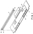
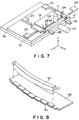
- Figure 1 is a schematic perspective view of the structure of an example of an ink jet head of an extended width produced using the production method in accordance with the present invention.
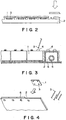
- FIG. 2 is a schematic view of the first embodiment of the ink jet head production method in accordance with the present invention, in which the heater boards are directly placed on the base plate, and fixed thereto with adhesive.
- Figure 3 is a schematic view of the second embodiment of the ink jet head production method in accordance with the present invention.
- Figure 4 is a schematic view of the third embodiment of the ink jet head in accordance with the present invention.
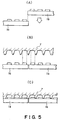
- Figure 5 is a schematic view of the fourth embodiment of the ink jet head production method in accordance with the present invention.
- Figure 6 is a schematic view of the sixth embodiment of the ink jet head in accordance with the present invention.
- Figure 7 is a schematic perspective view of an example of an assembly apparatus used in the ink jet head production method in accordance with the present invention.
- Figure 8 is a schematic view of the fourth embodiment of the ink jet head production method in accordance with the present invention.
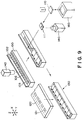
- Figure 9 is a perspective view of the general structure of the seventh embodiment of the present invention.
- Figure 10(A) illustrates a state of the seventh embodiment, in which an optical observation system 143 has been moved to the edge of the top plate member 100
- Figure 10(B) illustrates an image observed through the optical observation system 143.
- Figure 11 illustrates how the ink path location and orifice plate location on the deformed top plate are computed, wherein (A) illustrates a state in which the optical observation system 143, which always moves to the same point, relative to the X direction, is picking up the image, and (B) - (D) illustrate images picked up at pick-up points a, b and c, correspondingly, indicated in (A).
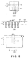
- Figure 12 illustrates how the heater location on the heater board, and the heater board edge location, are computed, wherein (A) gives an image of the heater board 110 picked up through the optical observation system 143, and (B) and (C) depict states, respectively, immediately before the top plate member 100 and heater board 110 are joined.
- Figure 13 is a schematic perspective view of the eighth embodiment of the present invention, illustrating a method for precisely computing the heater board location and orientation.
- Figure 14 is an explanatory drawing for the eighth embodiment of the present invention, describing how the images of both edge surface locations of the heater board are picked up in order to compute precisely the beater board location.
- Figure 15 is also an explanatory drawing for the eighth embodiment of the present invention, describing a method for computing the heater board skew from the data obtained by picking up the image of both edge surfaces of the heater board in order to compute precisely the heater board orientation.
- Figure 1 is a schematic perspective view of the structure of an example of an ink jet head of an extended width produced using the production method in accordance with the present invention.
- the ink jet head illustrated in Figure 1 is of a full-line type (extended type). Its ink ejection orifice density is 360 dpi (70.5 ⁇ m), and the number of the ink ejection orifices is 3,008 (printing width: 212 mm). It comprises a base plate 2 formed of metallic or ceramic material, or the like.
- each of the heater boards 1 plural heaters 10, as energy generating elements, are aligned at a predetermined pitch in the same direction as the heater board arrangement direction, along the same edge of the base plate 2.
- the heater 10 as the energy generating element used in this embodiment is an electrothermal transducer for ejecting the ink, but the present invention is not limited by this embodiment; a laminated piezoelectric element may be employed in place of the electrothermal transducer as the heater 10.
- a wiring substrate 12 comprising signal lines and power supply lines to be connected to the power supply pads of each heater board 1 is fixed in such a manner that the power supply pads on the heater board 1, hold a predetermined positional relationship with the signal-power supply pads provided on the wiring substrate 12.
- the power supply pads on the heater board 1 and the signal-power supply pads provided on the wiring substrate 12 are electrically connected with gold wire 11 or the like.
- a connector 13 for supplying external printing signals or driving power is attached.
- a top plate 7 is placed from above in such a manner that is covers the surfaces of plural heater boards 1, and is glued thereto.
- the top plate 7 is formed of a resin material, and receives the ink externally through an ink supply pin 18 provided at each end of the top plate 7.
- a concavity (unillustrated) is formed, which is connected to the ink supply pins 18 and constitutes a common liquid chamber for storing the ink.
- the top plate 7 comprises plural ink path grooves (unillustrated), each of which is formed to correspond to one of the heaters 10, and plural ink ejection orifices 17, each of which is formed to correspond to one of the ink path grooves. These grooves and orifices are formed using an excimer laser or the like.
- the common liquid chamber concavity, ink path grooves, and ink ejection orifices 17 may be formed by machining, etching, and the like.
- the ink which is supplied by way of an ink supply port 18 into the common liquid chamber concavity, and is temporarily stored therein, invades into each ink path groove due to capillarity, and forms a meniscus at the ink ejection orifice 17.
- the formed meniscus keeps the ink path groove filled with the ink.
- power is supplied to predetermined heaters 10 from an external apparatus, through the connector 13 and wiring substrate 12 illustrated in Figure 1, causing the predetermined heaters 10 to generate heat.
- the predetermined heaters 10 As the heat is generated, the ink on the heater 10 is suddenly heated to generate bubbles in the ink path. Then, as the bubbles expand, the ink is ejected from predetermined ink ejection orifices.
- the present invention is also applicable to an ink jet head recording apparatus, which comprises such an ink jet head as described above, and records images by ejecting the ink from the ink ejection orifices of the ink jet head in response to recording signals.
- FIG. 2 is a schematic view of the first embodiment of the ink jet head production method in accordance with the present invention, in which the heater boards are directly fixed to the base plate using adhesive.
- a frame-like pattern is formed on the base plate 2, on the surface where the heater boards 1 are to be aligned, and then, adhesive 3 is coated in advance on the base plate 2, on the area with the frame-like pattern.
- the heater boards 1, the locations of which have been fixed in a different processing area using a non-contact method are aligned on the base plate 2 in a single line, at the corresponding locations coated with the adhesive 3, maintaining a predetermined interval between the adjacent heater boards 1.
- each heater board 1 is sucked onto the base plate 2 using the suction hole (unillustrated) provided in each segment of the frame-like pattern coated with the adhesive. The suction is stopped when the adhesive 3 is cured.
- the amount of the adhesive 3 must be moderate, but sufficient, to prevent the adhesive 3 from oozing out of the adhesive coating area. Further, the heater boards are aligned so that the ill effects of non-uniformity in the cutting accuracy of the heater board can be canceled by the provision of the gap between the adjacent heater boards.
- the heater board is directly placed on the base plate, the evenness of the top surface of one aligned heater board with the top surfaces of the other aligned heater boards is improved.
- Figure 3 is a schematic view of the second embodiment of the ink jet head production method in accordance with the present invention.
- the adhesive when the heater boards are placed on the base plate, the adhesive is coated in advance on the base plate, but in this embodiment, adhesive 3 is injected to fix each heater board 1 after each heater board 1 is placed on the base plate 2, which is accomplished in the following manner. That is, referring to Figure 4, the base plate 2 is processed to provide it with suction holes 5 for securing the heater board 1, frame-like patterns constituting adhesive coating areas 6, and adhesive injection openings 4 through which the adhesive 3 can be injected from outside the heater boards 1 into the adhesive coating areas 6 after the heater boards are placed at the predetermined locations in the adhesive coating areas 6.
- the heater boards 1, the locations of which are fixed in a different processing area using the non-contact method, are aligned in a single line on the base plate 2 as they are in the first embodiment, and then; they are secured by suction through the suction holes 4. Thereafter, the adhesive 3 is injected into the adhesive coating areas 6 through the adhesive injection openings 4. It should be noted here that the adhesive 3 may be injected as each heater board 1 is placed and secured, or may be injected all at once after all the heater boards 1 are placed and secured. The suction through the suction holes 5 is stopped after the adhesive 3 is cured.
- the locations of the adhesive injection openings 4 are not limited to those illustrated in Figure 3; the locations are optional as long as the openings 4 are formed to lead to the adhesive coating area 6 located under the heater boards 1.
- Figure 4 is a schematic view of the third embodiment of the ink jet head production method in accordance with the present invention.
- the adhesive 3 is coated on the base plate side, whereas it this embodiment, the adhesive 3 is coated on the side of the heater board 1, and then, the heater board 1 is pressed onto the base plate 2, as shown in Figure 4.
- the adhesive 3 is coated on the back surfaces of the heater boards 1, on one to several points. In this case, the adhesive 3 must be coated so as to avoid the suction holes 5 provided on the base plate 2.
- the heater boards 1 are aligned in a single line on the base plate 2, and secured as they are sucked through the suction holes 5.
- the suction is stopped after the adhesive 3 is cured as it is in the first and second embodiments.
- silicic adhesive with a small curing shrinkage is employed to prevent the heater boards 2 from shifting as the adhesive 3 is cured.
- the material for the adhesive 3 in this embodiment is also the same as the material used in the first and second embodiments.
- Figure 5 is a schematic view of the fourth embodiment of the ink jet-head production method in accordance with the present invention.
- range which does not interfere with the ejection performance is a range in which each heater on the heater board remains within the boundary of the corresponding ink path groove of the top plate 7 ( ⁇ 8 ⁇ m).
- each heater is reliably placed within the boundary of the corresponding ink path groove, as shown in Figure 5(C), creating no printing problem.
- the heater board which is placed next to the displaced heater board 1b is such a heater board that has a size error which requires the heater board to be displaced in the direction opposite to the direction in which the preceding heater board 1b has been displaced.
- the sizes of the heater boards are measured by the non-contact method, and then, based on the measured sizes, the heater boards are paired to satisfy the alignment requirement between the heaters and grooves. Thereafter, they are aligned in a single line. More specifically, the heater boards are grouped into separate trays by their width in the alignment direction, using non-contact means such as image processing. Then, computation is made, based on the grouping data, to search for several combinations of the heater boards with different widths, which allows each heater of the heater boards to be within the boundary of the corresponding ink path groove of the extended top plate 7, so that a heater board combination most suitable for each of the extended top plates 7 can be employed. It is also acceptable that the sizes of the heater boards are measured immediately before placing them on the base plate 2, and the placement location of each heater board is adjusted on the basis of its measured size.
- the present invention is applicable to compensate for errors in the ink path groove pitch of the extended top plate.
- the location of each ink path groove correspondent to one of the heaters of the heater boards is measured in advance by the non-contact method in a different processing area, or measured by the same non-contact method immediately before the heater board placement, and then, the heater board arrangement may be adjusted on the basis of the measurement date obtained in the aforementioned manner, so that each heater reliably falls within the boundary of the correspondent nozzle.
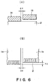
- FIGS. 6(A) and 6(B) are schematic drawings depicting the fifth embodiment of the ink jet head production method in accordance with the present invention, in which methods for positioning the heater boards when abutting the heater boards against the base plate are illustrated.
- an alphanumeric reference 1a designates a preceding heater board
- 1b a heater board placed next
- a referential symbol ⁇ x a gap between the adjacent heater boards
- ⁇ y designates the placement error of the adjacent heater board 1b in the ink ejection direction.
- the heater board 1b to be placed next is temporarily held above the base plate 2, and the gap ⁇ x between itself and the adjacent heater board is measured by the non-contact method, in order to fix its location in the horizontal direction.
- the value of the heater board gap ⁇ x can be changed according to the degree of non-uniformity in the heater board cutting accuracy.
- the heater board is suspended above the base plate 2, and then, the heater board location is detected from above by the same non-contact method such as image procesing, and then, the heater board 1b to be placed next is moved so that the amount of the placement error ⁇ y in the ink ejection direction is reduced to zero.
- the heater board 1b After the location of the heater board 1b is fixed in the aforementioned two directions, the heater board 1b is placed on the base plate 2 to be aligned.
- the heater board placement error in terms of the gap ⁇ x between the adjacent two heater boards becomes no more than ⁇ 1 ⁇ m, and the heater board placement error ⁇ y in the ink ejection direction becomes no more than ⁇ 2 ⁇ m.
- Figure 7 is a schematic perspective view of an example of an assembly apparatus used in the ink jet head production method in accordance with the present invention.
- a top plate 57 illustrated in Figure 8 also has ink ejection orifices, and is produced using injection molding or the like. However, this top plate 57 is different from the top plate 7 illustrated in Figure 1 in that it is slightly deformed (warped). Therefore, the arrangement of the heater boards 51 is adjusted to match the deformation.
- the warpage of the top plate 57 is measured using a non-contact means such as image processing or a laser-based measuring device. Then, the location of each heater board 51 is moved in the ink ejection direction or the opposite direction thereto, according to the warpage of the top plate 57 at the essential contact point between the heater board 51 and top plate 57. It should be noted here that the locational adjustment of the heater board 51 is made only in the ink ejection direction or the opposite direction thereto; the angle of the heater board 51 relative to the rotational direction in the horizontal plane is not adjusted, and also, the location of the heater board 51 relative to the lateral direction is not adjusted.
- this amount is set at 10 ⁇ m. This value may be varied according to the design of the top plate 57.
- This embodiment shows an example of the methods for measuring the warpage of the top plate 57 in the fifth embodiment.
- the overall warpage of the top plate 57 is measured using non-contact means such as image processing or a laser-based measuring device, so that it can be determined whether or not the arrangement locations should be adjusted.
- non-contact means such as image processing or a laser-based measuring device.
- a measurement is taken at the essential contact points between the top plate 57 and heater board 51 where adhesion is critical, using non-contact means such as real-time image processing or a laser-based measuring device.
- a measurement is taken at a point of the section called orifice plate, which has the ink ejection orifices.
- the arrangement location of the heater board 51 is adjusted in the ink ejection direction or the opposite direction thereto while measuring the warpage of the top plate 57 at the point of the orifice plate of the top plate 57.
- the gap between the top plate 57 and heater board 51 becomes no more than 5 ⁇ m.
- Figure 9 is an explanatory perspective view depicting the general steps taken in the seventh embodiment.
- a reference numeral 100 designates a top plate member, in which ink path grooves 102, an orifice plate 103, and nozzle holes 105 are formed in advance.
- the top plate member 100 is held with an unillustrated jig, so that the ink path grooves 102 face upward.
- the top plate member 100 held in such a manner can be movable in the directions of arrows X and Y, using a Y stage (unillustrated) for moving the top plate member 100 from the component entry point to a processing point, and an X Stage (unillustrated) for moving the top plate member from the processing point to the joining point where the base plate is joined.
- a reference numeral 110 designates a heater board, which is positioned to make ink heating heaters 111 face downward.
- a reference numeral 120 designates a base plate, which is coated with adhesive 121 so that it can be adhered to a nozzle unit 130, which will be described below.
- the heater board 110 is clasped with a finger 160. Its location and orientation can be controlled in 6 directions X, Y and Z; ⁇ , ⁇ x and ⁇ y, using an automatic stage (unillustrated) which supports the finger 160.
- an optical observation system 140 for computing the heater location of the heater board 110, and the edge surface location of the heater board 110.
- an optical observation system 143 for detecting the location of the orifice plate 103 of the top plate member 103, and measuring the amount of the orifice plate deformation.
- the optical observation system 143 is movable in the longitudinal direction (X direction), and horizontal direction (Z direction), of the top plate member 100.
- the top plate member 100 in which the ink path grooves and nozzle holes have been formed in the preceding steps, is fixed so that it does not become loose while it is transferred from one point to the other, or while it is assembled with the other components.
- the optical observation system 143 is moved to the edge of the top plate member 100, by controlling the automatic stages X and Y.
- Figure 10(A) illustrates a state in which the optical observation system 143 has been moved to the edge of the top plate member 100.
- Figure 10(B) illustrates the image obtained through the optical observation system.
- top plate members 100 are not uniform; some of them become deformed while they are molded or processed.
- Figure 11(A) depicts how the deformed top plate member 100 is measured.
- the optical observation system 143 is designed to move in such a manner that the locations at which it picks up the images are always the same locations relative to the X direction. But, since the top plate member 100 is deformed, the images picked up at observation points a, b and c illustrated in Figure 11(A) look as illustrated in Figures 11(B), 11(C) and 11(D), correspondingly.
- referential symbols X ⁇ and Y ⁇ designate referential lines in the X and Y directions, respectively.
- the location of the orifice plate 103 of the top plate member 100 coincides with Y ⁇ , whereas when the top plate member 100 is deformed, the location of the orifice plate 103 is Y1.
- This image is processed to compute the amount of the deformation ⁇ Y at the observation point a.
- ⁇ Y ⁇ Y1 - Y ⁇
- the amount of the deformation of each top plate 100 is measured at optional observation points, so that the deformation corresponding to the top plate 100 can be measured.
- the measured amount of the deformation is stored in an unillustrated control computer.
- the top plate member 100 is transferred from the top plate observation point to the joining point where the heater board 110 and top plate member 100 are joined.
- the heater board 110 on which the ink heating heaters have been formed, is placed, with the heater side facing downward, on the finger 160, which Serves as positioning plate for temporarily positioning the heater board 110.
- the heater board 110 is positioned with a reproducibility of no more than 10 ⁇ m.
- the positioned heater board 110 is clasped with the finger 160, and is moved upward to the point above the optical observation system 140 for determining heater position, as the finger moving stage is moved.
- Figure 12(A) illustrates an image of the heater board 110 obtained through the optical observation system 140.
- alphanumeric references x0 and y0 designate referential lines in the X and Y directions, respectively, in the image processing area.
- the edge surface location of the heater board 110 in the Y direction coincides with y0, whereas when the temporary positioning of the heater board 110 is inaccurate, that is, when positioning accuracy is not uniform, the edge surface location of the heater board 110 becomes y1.
- the values of the measured errors are stored in an unillustrated control computer.
- the finger 160 is moved, whereby the heater board 110 is transferred to the joining point where tee heater board 110 and top plate member 100 are joined, and is left on standby above the ink path grooves 102.
- Figures 12(B) and 12(C) show the positional relationship between the top plate member 100 and heater board 110 immediately before they are joined. Referring to Figure 12(B), it is assumed that according to measurement, the location of the top plate member 100 is off by ⁇ X and ⁇ Y from corresponding joining reference lines, and the location of the heater board 110 is off by ⁇ x and ⁇ y.
- the step described above is repeated by the number of heater boards 110.
- the top plate 100 and heater boards 110 which are joined in the aforementioned manner, constitute a nozzle unit 130, which is transferred to the point where the base plate is joined.
- the base plate 120 coated in advance with the adhesive 121 is on standby above the base plate joining location. This base plate 120 is lowered and joined with the nozzle unit 130, producing an ink jet head with an extended width.
- Figures 13 - 15 depict the eighth embodiment of the present invention.
- This embodiment improves the accuracy with which the top plate member 100 and heater board 110 are joined in the seventh embodiment.
- FIG 13 is a schematic perspective view of the essential structure of the eighth embodiment.
- reference numerals 141 and 142 are optical observation systems for computing the edge surface location of the heater board 110, and the heater locations.
- the optical observation systems 141 and 142 are disposed as illustrated in Figure 13, so that the images of both edges of the heater board 110 can be picked up at the same time through a mirror 163.
- Figures 14(A) and 14(B) illustrate examples of the images picked up by the optical observation systems 141 and 142.
- the optical system arrangement illustrated in Figure 13 is for adjusting the heater board 110 in the state described in the foregoing.
- the images picked up by the optical observation systems 141 and 142 are measured to compute the edge locations Y1 and Y2 of the heater board 110.
- the angle ⁇ computed in the aforementioned manner is used as the angle by which the ⁇ stage of the finger 160 clasping the skewed heater board 110 is moved to straighten the skewed heater board 110. Therefore, the skew of the heater board 110, which cannot be eliminated by the temporary positioning alone, can be eliminated.
- the present invention produces excellent results when used with a recording head, or a recording apparatus, employing any ink jet recording system, in particular, when used with a recording head, or a recording apparatus, employing the ink jet recording system in which thermal energy is used to form flying liquid droplets.
- the typical structure and the operational principle are preferably the ones disclosed in U.S. Patent Nos. 4,723,129 and 4,740,796.
- the principle and structure are applicable to a so-called on-demand type recording system and a continuous type recording system.
- it is suitable for the on-demand type because the principle is such that at least one driving signal is applied to an electrothermal transducer disposed on a liquid (ink) retaining sheet or liquid passage, the driving signal being enough to provide such a quick temperature rise beyond a departure from nucleation boiling point, by which the thermal energy is provided by the electrothermal transducer to produce film boiling on the heating portion of the recording head, whereby a bubble can be formed in the liquid (ink) corresponding to each of the driving signals.
- the liquid (ink) is ejected through an ejection outlet to produce at least one droplet.
- the driving signal is preferably in the form of a pulse, because the development and contraction of the bubble can be effected instantaneously, and therefore, the liquid (ink) is ejected with quick response.
- the driving signal in the form of the pulse is preferably such as disclosed in U.S. Patents Nos. 4,463,359 and 4,345,262.
- the temperature increasing rate of the heating surface is preferably such as disclosed in U.S. Patent No. 4,313,124.
- the structure of the recording head may be as shown in U.S. Patent Nos. 4,558,333 and 4,459,600 wherein the heating portion is disposed at a bent portion, as well as the structure of the combination of the ejection outlet, liquid passage and the electrothermal transducer as disclosed in the abovementioned patents.
- the present invention is applicable to the structure disclosed in Japanese Laid-Open Patent Application No. 123670/1984 wherein a common slit is used as the ejection outlet for plural electrothermal transducers, and to the structure disclosed in Japanese Laid-Open Patent Application No. 138461/1984 wherein an opening for absorbing pressure wave of the thermal energy is formed corresponding to the ejecting portion.
- the present invention is effectively applicable to a so-called full-line type recording head having a length corresponding to the maximum recording width.
- a recording head may comprise a single recording head and plural recording head combined to cover the maximum width.
- the present invention is applicable to a replaceable chip type recording head which is connected electrically with the main apparatus and can be supplied with the ink when it is mounted in the main assembly, or to a cartridge type recording head having an integral ink container.
- the provisions of the recovery means and/or the auxiliary means for the preliminary operation are preferable, because they can further stabilize the effects of the present invention.
- preliminary heating means which may be the electrothermal transducer, an additional heating element or a combination thereof.
- means for effecting preliminary ejection (not for the recording operation) can stabilize the recording operation.
- the recording head mountable may be a single corresponding to a single color ink, or may be plural corresponding to the plurality of ink materials having different recording color or density.
- the present invention is effectively applicable to an apparatus having at least one of a monochromatic mode mainly with black, a multi-color mode with different color ink materials and/or a full-color mode using the mixture of the colors, which may be an integrally formed recording unit or a combination of plural recording heads.
- the ink has been liquid. It may be, however, an ink material which is solidified below the room temperature but liquefied at the room temperature. Since the ink is controlled within the temperature not lower than 30 o C and not higher than 70 o C to stabilize the viscosity of the ink to provide the stabilized ejection in usual recording apparatus of this type, the ink may be such that it is liquid within the temperature range when the recording signal is the present invention is applicable to other types of ink.
- the temperature rise due to the thermal energy is positively prevented by consuming it for the state change of the ink from the solid estate to the liquid state.
- Another ink material is solidified when it is left, to prevent the evaporation of the ink.
- the application of the recording signal producing thermal energy the ink is liquefied, and the liquefied ink may be ejected.
- Another ink material may start to be solidified at the time when it reaches the recording material.
- the present invention is also applicable to such an ink material as is liquefied by the application of the thermal energy.
- Such an ink material may be retained as a liquid or solid material in through holes or recesses formed in a porous sheet as disclosed in Japanese Laid-Open Patent Application No. 56847/1979 and Japanese Laid-Open Patent Application No. 71260/1985. The sheet is faced to the electrothermal transducers. The most effective one for the ink materials described above is the film boiling system.
- the ink jet recording apparatus may be used as an output terminal of an information processing apparatus such as word processor, computer or the like, as a copying apparatus combined with an image reader or the like, or as a facsimile machine having information sending and receiving functions.
- an information processing apparatus such as word processor, computer or the like
- a copying apparatus combined with an image reader or the like
- a facsimile machine having information sending and receiving functions.
- An ink jet head manufacturing method includes steps of disposing a plurality of heater boards each having a plurality of energy generating elements, on a base plate; mounting on the base plate a top plate having a plurality of ink passage forming grooves corresponding to respective energy generating elements; the improvement residing in that in said disposing step, said heater boards are directly disposed with a gap between adjacent ones, and that in said mounting step, the top plate is bonded on the base plate.
Abstract
Description
- The present invention relates to a method for producing a full-line tee ink jet head comprising a base plate, plural heater substrates (hereinafter, heater board) arranged on the base plate in a predetermined manner, and a top plate assembled onto the base plate, wherein the heater substrates comprise plural energy generating elements (hereinafter, heater), and the top plate is provided with plural groves, each of which serves as a nozzle correspondent to one of heaters, and plural ink ejection orifices, each of which is connected to one of the grooves. The present invention also relates to an ink jet head, and an ink jet head recording apparatus.
- Japanese Laid-Open Patent Application No. 212162/1990 discloses a conventional recording head production method in which plural heater boards are aligned in such a manner that the end surfaces of each heater board are abutted against those of the adjacent heater boards
- Japanese Laid-Open Patent Application No: 229278/1992 discloses another method in which notched portions are formed in the part of the unit constituted of the heater boards and top plate, and the notched portion is abutted against a reference provided on the base plate.
- Japanese Laid-Open Patent Application No. 177942/1991 discloses another method in which a pattern is formed by means of irradiating light onto the base plate to form a pattern, and the formed pattern is combined with the pattern of an alignment substrate to form an array.
- However, each of the aforementioned examples of the conventional method suffers from the following shortcomings.
- The method disclosed in Japanese Laid-Open Patent Application No. 212162/1990 suffers from the following shortcomings.
- (1) The end surfaces of each heater board are abutted against those of the adjacent heater boards; therefore, the accuracy with which the heater board is cut at each end, results in the arrangement accuracy. Consequently, a high degree of accuracy is required of an apparatus used for cutting the heater board, which in turn requires a large amount of time and effort to maintain and control the cutting apparatus, making this method unsuitable for mass-production.
- (2) The end surfaces of the heater board are mechanically abutted to each other; therefore, the heater boards are liable to be damaged (fragmentation, cracking, chipping, or the like, of silicon substrate).
The method disclosed in Japanese Laid-Open Patent Application No. 229278/1992 suffers from the following shortcomings. - (3) A butting block must be produced to form the notched portion which serves as the reference, and this portion affects the accuracy with which the heater boards are arranged later; therefore, the production of the butting block requires a highly, precise mechanical process, which is extremely difficult.
All of the aforementioned methods suffer from the following shortcomings. - (4) It is difficult to regulate the stepped portion of the heater surface of the heater board; therefore, the stepped portion is liable to become the cause of ink ejection failure.
- (5) It is difficult to regulate the stepped portion which determines the ejection direction of each heater board; therefore, the stepped portion is liable to become the cause of ink ejection failure.
- (6) Even when the heater boards are accurately arranged, when the top plates are not processed uniformly, that is, when the top plates have deformations such as warping, gaps are created at the joint between the heater board and top plate, being liable to cause recording failure.
The method disclosed in Japanese Laid-Open Patent Application NO. 177042/1991 suffers from the following shortcomings. - (7) The alignment substrate must be of a material processable by light irradiation; therefore, the number of usable materials is limited.
- The present invention was made in consideration of the shortcomings of the conventional arts described above, and its primary object is to realize a recording head production method capable of precisely producing the heater board, without requiring high accuracy in the structural members, and without limiting the number of the usable materials.
- The present invention is characterized in that an ink jet head production method comprises a step in which plural heater boards, containing plural energy generating elements, are aligned on a base plate, and a step in which a top plate provided with plural ink path grooves, each of which is correspondent to one of the energy generating elements, is jointed with the base plate, wherein the heater boards are directly and fixedly placed on the base plate, with predetermined intervals, by means of gluing or the like.
- The heater board may be fixedly adhered to the base plate by means of abutting the heater board against the base plate after coating the back surface of the heater board with adhesive.
- Further, a predetermined frame-like pattern may be formed on the base plate surface on which the heater boards are aligned.
- Further, the heater boards may be aligned on the base plate to match the top plate configuration.
- In this case, the heater boards may be aligned on the base plate, on the basis of the top plate measurement which is taken in advance at a different processing location.
- Further, the heater boards may be aligned on the base plate, on the basis of the top plate measurement which is taken while aligning the heater boards.
- In either of the above cases, when the heater boards are aligned on the base plate, the location of the preceding heater board may be measured in a non-contact manner, and a succeeding heater board may be arranged on the basis of the results of the measurement.
- When the predetermined frame-like pattern is formed on the base plate surface on which the heater boards are aligned, the heater boards may be fixedly adhered to the base plate by means of placing the adhesive in advance in the frame-like pattern formed on the base plate.
- Further, the heater boards may be fixedly adhered to the base plate by means of allowing the adhesive to flow into the gaps formed between the heater boards and the frame-like pattern of the base plate, from the lateral sides of the heater boards, after the heater boards are abutted against the base plate.
- Further, the heater boards may be fixedly adhered to the base plate by means of allowing the adhesive to flow into the gaps formed between the heater boards and the frame-like pattern of the base plate, from the rear sides of the heater boards, after the heater boards are abutted against the base plate.
- According to another aspect of the present invention, the present invention is characterized in that a base plate, on which plural heater boards comprising plural ink heating heaters are aligned, is joined with a top plate member provided with the ink paths and ink ejection orifices, to produce an ink ejection head, wherein the heater boards are directly aligned on the top plate member, and fixedly glued thereto.
- In this case, the step for directly disposing the heater board on the top member may comprise:
an ink path location computing step for computing the ink path location in the top plate member;
a heater location computing step for computing the location of the ink heating heater on the heater board;
a location-orientation adjustment step for adjusting the location and orientation of the heater board;
a heater board joining step for forming a nozzle unit by means of joining the heater board and top plate in such a manner that the ink path location of the top plate is matched with the heater location of the heater board; and
a base plate joining step for joining the nozzle unit with a base plate for fixedly supporting the nozzle unit. - The ink path location comprising step may comprise:
a top member moving step for moving the top plate member from the top member entry location to the ink path location computing point where the ink path location is computed; and
a location computing first step for computing the location of the ejection ink path groove formed in the top plate member, and the location of the orifice tip. - The heater location computing step may comprise:
a heater board moving step for moving the heater board from the component entry point to the heater location computing point; and
a location computing second step for computing the location of the ink heating heater formed on the heater board, at the heater location computing point. - The location-orientation adjustment step is such a step, in which the location and orientation of the heater board is adjusted using heater board clasping means for clasping and moving the heater board, and may comprise:
a computing step for computing the amount of heater board location-orientation adjustment, on the basis of the location of the ejection ink path groove of the top plate member, and the location of the orifice tip, which are obtained by the location computing first step, and the heater location obtained by the location computing second step; and
a heater board location-orientation adjustment step for adjusting the heater board location and orientation, on the basis of the results of the computing step, using the heater board clasping means. - The heater board joining step may comprise:
a top plate member moving step for moving the top plate member from the ink path location computing point to a point where the top plate member and heater board are joined;
a heater board moving step for moving the heater board from the heater location computing point to a point where the top plate member and heater board are joined;
a joining step for joining the top plate member and heater board; and
a fixing step for stabilizing the state of fixation. - The base plate joining step may comprise:
a base plate moving step for moving the base plate from a base plate entry point to the base plate joining point;
an adhesive coating step for coating the base plate with adhesive which fixes the nozzle unit to the base plate; and
a joining step for joining the nozzle unit and base plate. - The ink jet head in accordance with the present invention is produced using one of the aforementioned production methods.
- In this case, the energy generating element may be an electrothermal transducer which generates thermal energy for ejecting the ink.
- Further, the ink jet head in accordance with the present invention may be such an ink jet head which ejects the ink from the ejection orifices using the film boiling triggered in the ink by the thermal energy applied by the electrothermal transducer.
- The ink jet recording apparatus in accordance with the present invention comprises such an ink jet head (or ink jet heads) as described above, and records images by means of ejecting the ink from the ejection orifices of the ink jet head, in response to recording signals.
- According to the present invention comprising the aforementioned steps, undesirable effects of non-uniformity in the cutting accuracy of the heater board can be canceled by the placement of the gap between the adjacent heater boards; therefore, even when the cutting accuracy of the base plate in the alignment direction is not uniform, the location of each of the aligned energy generating elements can be accurately matched with the location of the corresponding ink path groove formed in the top plate.
- The amount of the gap for realizing the aforementioned arrangement is measured using a non-contact method, and the arrangement is adjusted on the basis of the measurement results. In other words, the components are note located by means of mechanical processing, but instead, their locations are computed using a non-contact method, and then, the subsequent adjustment is made on the basis of the measurement results; therefore, the non-uniformity, which is liable to be caused by the mechanical processing, does not exist, affording accurate alignment.
- Since the heater boards are abutted against the base plate, the evenness of the top surface of one heater board with the top surfaces of the other heater boards is improved.
- A frame-like pattern is formed on the base plate; therefore, foreign matter such as dust is prevented from invading the area surrounded by the frame-like pattern.
- According to the second aspect of the present invention, the heater boards can be aligned according to the degree of warpage which occurs to the top plate during the formation thereof; therefore, the heater boards can be accurately aligned on the top plate.
- These and other objects, features and advantages of the present invention will become more apparent upon a consideration of the following description of the preferred embodiments of the present invention taken in conjunction with the accompanying drawings.
- Figure 1 is a schematic perspective view of the structure of an example of an ink jet head of an extended width produced using the production method in accordance with the present invention.
- Figure 2 is a schematic view of the first embodiment of the ink jet head production method in accordance with the present invention, in which the heater boards are directly placed on the base plate, and fixed thereto with adhesive.
- Figure 3 is a schematic view of the second embodiment of the ink jet head production method in accordance with the present invention.
- Figure 4 is a schematic view of the third embodiment of the ink jet head in accordance with the present invention.
- Figure 5 is a schematic view of the fourth embodiment of the ink jet head production method in accordance with the present invention.
- Figure 6 is a schematic view of the sixth embodiment of the ink jet head in accordance with the present invention.
- Figure 7 is a schematic perspective view of an example of an assembly apparatus used in the ink jet head production method in accordance with the present invention.
- Figure 8 is a schematic view of the fourth embodiment of the ink jet head production method in accordance with the present invention.
- Figure 9 is a perspective view of the general structure of the seventh embodiment of the present invention.
- Figure 10(A) illustrates a state of the seventh embodiment, in which an
optical observation system 143 has been moved to the edge of thetop plate member 100, and Figure 10(B) illustrates an image observed through theoptical observation system 143. - Figure 11 illustrates how the ink path location and orifice plate location on the deformed top plate are computed, wherein (A) illustrates a state in which the
optical observation system 143, which always moves to the same point, relative to the X direction, is picking up the image, and (B) - (D) illustrate images picked up at pick-up points a, b and c, correspondingly, indicated in (A). - Figure 12 illustrates how the heater location on the heater board, and the heater board edge location, are computed, wherein (A) gives an image of the
heater board 110 picked up through theoptical observation system 143, and (B) and (C) depict states, respectively, immediately before thetop plate member 100 andheater board 110 are joined. - Figure 13 is a schematic perspective view of the eighth embodiment of the present invention, illustrating a method for precisely computing the heater board location and orientation.
- Figure 14 is an explanatory drawing for the eighth embodiment of the present invention, describing how the images of both edge surface locations of the heater board are picked up in order to compute precisely the beater board location.
- Figure 15 is also an explanatory drawing for the eighth embodiment of the present invention, describing a method for computing the heater board skew from the data obtained by picking up the image of both edge surfaces of the heater board in order to compute precisely the heater board orientation.
- Hereinafter, the embodiments of the present invention will be described with reference to the drawings.
- Figure 1 is a schematic perspective view of the structure of an example of an ink jet head of an extended width produced using the production method in accordance with the present invention.
- The ink jet head illustrated in Figure 1 is of a full-line type (extended type). Its ink ejection orifice density is 360 dpi (70.5 µm), and the number of the ink ejection orifices is 3,008 (printing width: 212 mm). It comprises a
base plate 2 formed of metallic or ceramic material, or the like. - On the
base plate 2, plural heater boards, as substrates, composed of glass, Si, or the like, are arranged in a straight line along one of the edges of thebase plate 2. - On each of the
heater boards 1,plural heaters 10, as energy generating elements, are aligned at a predetermined pitch in the same direction as the heater board arrangement direction, along the same edge of thebase plate 2. - Also on each of the
heater boards 1, power supply pads are aligned in the same direction as the heater board alignment direction, along the edge opposite to the edge along which theheaters 10 are aligned. Theheater 10 as the energy generating element used in this embodiment is an electrothermal transducer for ejecting the ink, but the present invention is not limited by this embodiment; a laminated piezoelectric element may be employed in place of the electrothermal transducer as theheater 10. - Also on the
base plate 2, awiring substrate 12 comprising signal lines and power supply lines to be connected to the power supply pads of eachheater board 1 is fixed in such a manner that the power supply pads on theheater board 1, hold a predetermined positional relationship with the signal-power supply pads provided on thewiring substrate 12. The power supply pads on theheater board 1 and the signal-power supply pads provided on thewiring substrate 12 are electrically connected with gold wire 11 or the like. - On the
wiring substrate 12, aconnector 13 for supplying external printing signals or driving power is attached. - A
top plate 7 is placed from above in such a manner that is covers the surfaces ofplural heater boards 1, and is glued thereto. Thetop plate 7 is formed of a resin material, and receives the ink externally through anink supply pin 18 provided at each end of thetop plate 7. Within thetop plate 7, a concavity (unillustrated) is formed, which is connected to the ink supply pins 18 and constitutes a common liquid chamber for storing the ink. Further, thetop plate 7 comprises plural ink path grooves (unillustrated), each of which is formed to correspond to one of theheaters 10, and pluralink ejection orifices 17, each of which is formed to correspond to one of the ink path grooves. These grooves and orifices are formed using an excimer laser or the like. - When the
top plate 7 is formed using glass or metallic material, the common liquid chamber concavity, ink path grooves, andink ejection orifices 17 may be formed by machining, etching, and the like. - At this point, it will be described how the ink is ejected from each
ink ejection orifice 17. The ink, which is supplied by way of anink supply port 18 into the common liquid chamber concavity, and is temporarily stored therein, invades into each ink path groove due to capillarity, and forms a meniscus at theink ejection orifice 17. The formed meniscus keeps the ink path groove filled with the ink. In this state, power is supplied topredetermined heaters 10 from an external apparatus, through theconnector 13 andwiring substrate 12 illustrated in Figure 1, causing thepredetermined heaters 10 to generate heat. As the heat is generated, the ink on theheater 10 is suddenly heated to generate bubbles in the ink path. Then, as the bubbles expand, the ink is ejected from predetermined ink ejection orifices. - The present invention is also applicable to an ink jet head recording apparatus, which comprises such an ink jet head as described above, and records images by ejecting the ink from the ink ejection orifices of the ink jet head in response to recording signals.
- Next, descriptions will be given as to various methods for aligning plural heater boards on the base plate during the production of the ink jet head with the structure described above.
- Figure 2 is a schematic view of the first embodiment of the ink jet head production method in accordance with the present invention, in which the heater boards are directly fixed to the base plate using adhesive.
- Referring to Figure 2, according to the production method in this embodiment, a frame-like pattern is formed on the
base plate 2, on the surface where theheater boards 1 are to be aligned, and then, adhesive 3 is coated in advance on thebase plate 2, on the area with the frame-like pattern. Next, theheater boards 1, the locations of which have been fixed in a different processing area using a non-contact method, are aligned on thebase plate 2 in a single line, at the corresponding locations coated with the adhesive 3, maintaining a predetermined interval between theadjacent heater boards 1. Then, eachheater board 1 is sucked onto thebase plate 2 using the suction hole (unillustrated) provided in each segment of the frame-like pattern coated with the adhesive. The suction is stopped when the adhesive 3 is cured. - It should be noted here that the amount of the adhesive 3 must be moderate, but sufficient, to prevent the adhesive 3 from oozing out of the adhesive coating area. Further, the heater boards are aligned so that the ill effects of non-uniformity in the cutting accuracy of the heater board can be canceled by the provision of the gap between the adjacent heater boards.
- Since the heater board is directly placed on the base plate, the evenness of the top surface of one aligned heater board with the top surfaces of the other aligned heater boards is improved.
- Figure 3 is a schematic view of the second embodiment of the ink jet head production method in accordance with the present invention.
- In the first embodiment, when the heater boards are placed on the base plate, the adhesive is coated in advance on the base plate, but in this embodiment, adhesive 3 is injected to fix each
heater board 1 after eachheater board 1 is placed on thebase plate 2, which is accomplished in the following manner. That is, referring to Figure 4, thebase plate 2 is processed to provide it withsuction holes 5 for securing theheater board 1, frame-like patterns constitutingadhesive coating areas 6, andadhesive injection openings 4 through which the adhesive 3 can be injected from outside theheater boards 1 into theadhesive coating areas 6 after the heater boards are placed at the predetermined locations in theadhesive coating areas 6. - More specifically, the
heater boards 1, the locations of which are fixed in a different processing area using the non-contact method, are aligned in a single line on thebase plate 2 as they are in the first embodiment, and then; they are secured by suction through the suction holes 4. Thereafter, the adhesive 3 is injected into theadhesive coating areas 6 through theadhesive injection openings 4. It should be noted here that the adhesive 3 may be injected as eachheater board 1 is placed and secured, or may be injected all at once after all theheater boards 1 are placed and secured. The suction through the suction holes 5 is stopped after the adhesive 3 is cured. - It should also be noted here that the locations of the
adhesive injection openings 4 are not limited to those illustrated in Figure 3; the locations are optional as long as theopenings 4 are formed to lead to theadhesive coating area 6 located under theheater boards 1. - Figure 4 is a schematic view of the third embodiment of the ink jet head production method in accordance with the present invention.
- In the first and second embodiments described above, the adhesive 3 is coated on the base plate side, whereas it this embodiment, the adhesive 3 is coated on the side of the
heater board 1, and then, theheater board 1 is pressed onto thebase plate 2, as shown in Figure 4. - More specifically, before the
heater boards 1, the locations of which have been fixed in a different processing area as they have been in the first and second embodiments, are placed on thebase plate 2, the adhesive 3 is coated on the back surfaces of theheater boards 1, on one to several points. In this case, the adhesive 3 must be coated so as to avoid the suction holes 5 provided on thebase plate 2. - Then, the
heater boards 1 are aligned in a single line on thebase plate 2, and secured as they are sucked through the suction holes 5. The suction is stopped after the adhesive 3 is cured as it is in the first and second embodiments. - As for the adhesive 3, silicic adhesive with a small curing shrinkage is employed to prevent the
heater boards 2 from shifting as the adhesive 3 is cured. The material for the adhesive 3 in this embodiment is also the same as the material used in the first and second embodiments. - Figure 5 is a schematic view of the fourth embodiment of the ink jet-head production method in accordance with the present invention.
- Referring to Figure 5(A), it is assumed in this case that the sizes of heater boards 1a and 1b are not uniform (accurate); the size error of a heater board 1a is within the cutting tolerance of the heater board, and the size error of a heater board 1b exceeds the cutting tolerance of the heater board. When such heater boards 1a and 1b are placed next to each other, at the normal arrangement points, respectively, they interfere with each other at the adjacent ends. In this embodiment, therefore, the heater board 1b is slightly shifted in the alignment direction, within a range which does not interfere with ejection performance, as shown in Figure 5(B).
- Further, even when the size errors of all heater boards fall within the cutting tolerance, if the distance between one end of a heater board and the closest heater on the same heater board is extremely different from the distance between the other end of the same heater and the closest heater on the same board, the location for such a heater board is shifted in the alignment direction, toward the processing heater board or away from it, within a range which does not interfere with the ejection performance.
- In this embodiment, "range which does not interfere with the ejection performance" is a range in which each heater on the heater board remains within the boundary of the corresponding ink path groove of the top plate 7 (±8 µm).
- As a result, when the
top plate 7 is joined, each heater is reliably placed within the boundary of the corresponding ink path groove, as shown in Figure 5(C), creating no printing problem. - It is preferred that the heater board which is placed next to the displaced heater board 1b is such a heater board that has a size error which requires the heater board to be displaced in the direction opposite to the direction in which the preceding heater board 1b has been displaced.
- In this case, the sizes of the heater boards are measured by the non-contact method, and then, based on the measured sizes, the heater boards are paired to satisfy the alignment requirement between the heaters and grooves. Thereafter, they are aligned in a single line. More specifically, the heater boards are grouped into separate trays by their width in the alignment direction, using non-contact means such as image processing. Then, computation is made, based on the grouping data, to search for several combinations of the heater boards with different widths, which allows each heater of the heater boards to be within the boundary of the corresponding ink path groove of the extended
top plate 7, so that a heater board combination most suitable for each of the extendedtop plates 7 can be employed. It is also acceptable that the sizes of the heater boards are measured immediately before placing them on thebase plate 2, and the placement location of each heater board is adjusted on the basis of its measured size. - Further, the present invention is applicable to compensate for errors in the ink path groove pitch of the extended top plate.
- More specifically, when an elongated top plate produced by injection molding or the like is processed using an excimer laser or the like to form the ink path grooves and ejection orifices thereon, errors sometimes occur in the ink path groove pitch (pitch error) due to processing errors. In such cases, the location of each ink path groove correspondent to one of the heaters of the heater boards is measured in advance by the non-contact method in a different processing area, or measured by the same non-contact method immediately before the heater board placement, and then, the heater board arrangement may be adjusted on the basis of the measurement date obtained in the aforementioned manner, so that each heater reliably falls within the boundary of the correspondent nozzle.
- Figures 6(A) and 6(B) are schematic drawings depicting the fifth embodiment of the ink jet head production method in accordance with the present invention, in which methods for positioning the heater boards when abutting the heater boards against the base plate are illustrated. In these drawings, an alphanumeric reference 1a designates a preceding heater board; 1b, a heater board placed next; a referential symbol Δx, a gap between the adjacent heater boards; and Δy designates the placement error of the adjacent heater board 1b in the ink ejection direction.
- In the first to fourth embodiments described above, before the heater boards are aligned on the base plate, their locations must be fixed. Therefore, one of the methods for fixing the heater board locations will be described below.
- Referring to Figure 6(A), in this embodiment of the production method, the heater board 1b to be placed next is temporarily held above the
base plate 2, and the gap Δx between itself and the adjacent heater board is measured by the non-contact method, in order to fix its location in the horizontal direction. In this chase, the value of the heater board gap Δx can be changed according to the degree of non-uniformity in the heater board cutting accuracy. - Referring to Figure 6(B), as for the heater board placement error in the ink ejection direction, the heater board is suspended above the
base plate 2, and then, the heater board location is detected from above by the same non-contact method such as image procesing, and then, the heater board 1b to be placed next is moved so that the amount of the placement error Δy in the ink ejection direction is reduced to zero. - After the location of the heater board 1b is fixed in the aforementioned two directions, the heater board 1b is placed on the
base plate 2 to be aligned. - Consequently, the heater board placement error in terms of the gap Δx between the adjacent two heater boards becomes no more than ±1 µm, and the heater board placement error Δy in the ink ejection direction becomes no more than ±2 µm.
- Figure 7 is a schematic perspective view of an example of an assembly apparatus used in the ink jet head production method in accordance with the present invention.
- A
top plate 57 illustrated in Figure 8 also has ink ejection orifices, and is produced using injection molding or the like. However, thistop plate 57 is different from thetop plate 7 illustrated in Figure 1 in that it is slightly deformed (warped). Therefore, the arrangement of theheater boards 51 is adjusted to match the deformation. - In this embodiment, the locational relationship among the
heater boards 51 andbase plate 52 will be described with reference to the top plate warpage in the ink ejection direction or the opposite direction thereto. - First, the warpage of the
top plate 57 is measured using a non-contact means such as image processing or a laser-based measuring device. Then, the location of eachheater board 51 is moved in the ink ejection direction or the opposite direction thereto, according to the warpage of thetop plate 57 at the essential contact point between theheater board 51 andtop plate 57. It should be noted here that the locational adjustment of theheater board 51 is made only in the ink ejection direction or the opposite direction thereto; the angle of theheater board 51 relative to the rotational direction in the horizontal plane is not adjusted, and also, the location of theheater board 51 relative to the lateral direction is not adjusted. - When the warpage of the
top plate 57 is no more than a predetermined amount, the adjustment is not made. In this embodiment, this amount is set at 10 µm. This value may be varied according to the design of thetop plate 57. - Next, the sixth embodiment of the ink jet head production method in accordance with the present invention will be described.
- This embodiment shows an example of the methods for measuring the warpage of the
top plate 57 in the fifth embodiment. - In this embodiments, the overall warpage of the
top plate 57 is measured using non-contact means such as image processing or a laser-based measuring device, so that it can be determined whether or not the arrangement locations should be adjusted. When adjusted, a measurement is taken at the essential contact points between thetop plate 57 andheater board 51 where adhesion is critical, using non-contact means such as real-time image processing or a laser-based measuring device. In the case of this embodiment, a measurement is taken at a point of the section called orifice plate, which has the ink ejection orifices. In actual practice, the arrangement location of theheater board 51 is adjusted in the ink ejection direction or the opposite direction thereto while measuring the warpage of thetop plate 57 at the point of the orifice plate of thetop plate 57. - It is also acceptable to measure in advance the top plate warpage at a separate processing area, and then to adjust the arrangement location data on the basis of the measured warpage.
- As a result, the gap between the
top plate 57 andheater board 51 becomes no more than 5 µm. - Next, the seventh embodiment of the ink jet head production method in accordance with the present invention will be described.
- Figure 9 is an explanatory perspective view depicting the general steps taken in the seventh embodiment.
- In this embodiment, one of the automated versions of the preceding embodiments will be described. Referring to Figure 9, a
reference numeral 100 designates a top plate member, in whichink path grooves 102, anorifice plate 103, andnozzle holes 105 are formed in advance. - The
top plate member 100 is held with an unillustrated jig, so that theink path grooves 102 face upward. Thetop plate member 100 held in such a manner can be movable in the directions of arrows X and Y, using a Y stage (unillustrated) for moving thetop plate member 100 from the component entry point to a processing point, and an X Stage (unillustrated) for moving the top plate member from the processing point to the joining point where the base plate is joined. - A
reference numeral 110 designates a heater board, which is positioned to make ink heating heaters 111 face downward. Areference numeral 120 designates a base plate, which is coated with adhesive 121 so that it can be adhered to anozzle unit 130, which will be described below. - The
heater board 110 is clasped with afinger 160. Its location and orientation can be controlled in 6 directions X, Y and Z; θ, θx and θy, using an automatic stage (unillustrated) which supports thefinger 160. - Located between a
positioning plate 160, which supplies theheater board 110 as it temporarily positions theheater board 110, and thetop plate 100, is anoptical observation system 140 for computing the heater location of theheater board 110, and the edge surface location of theheater board 110. - Located above the
top plate 110 is anoptical observation system 143 for detecting the location of theorifice plate 103 of thetop plate member 103, and measuring the amount of the orifice plate deformation. Theoptical observation system 143 is movable in the longitudinal direction (X direction), and horizontal direction (Z direction), of thetop plate member 100. - Next, a method for assembling the ink jet head using the above apparatus will be described.
- The
top plate member 100, in which the ink path grooves and nozzle holes have been formed in the preceding steps, is fixed so that it does not become loose while it is transferred from one point to the other, or while it is assembled with the other components. - Then, the
optical observation system 143 is moved to the edge of thetop plate member 100, by controlling the automatic stages X and Y. - Figure 10(A) illustrates a state in which the
optical observation system 143 has been moved to the edge of thetop plate member 100. Figure 10(B) illustrates the image obtained through the optical observation system. - Practically speaking, all
top plate members 100 are not uniform; some of them become deformed while they are molded or processed. Figure 11(A) depicts how the deformedtop plate member 100 is measured. - Referring to Figure 11(A), the
optical observation system 143 is designed to move in such a manner that the locations at which it picks up the images are always the same locations relative to the X direction. But, since thetop plate member 100 is deformed, the images picked up at observation points a, b and c illustrated in Figure 11(A) look as illustrated in Figures 11(B), 11(C) and 11(D), correspondingly. - Referring to Figure 11(B), referential symbols Xθ and Yθ designate referential lines in the X and Y directions, respectively. When the
top plate member 100 is not deformed, the location of theorifice plate 103 of thetop plate member 100 coincides with Yθ, whereas when thetop plate member 100 is deformed, the location of theorifice plate 103 is Y1. This image is processed to compute the amount of the deformation ΔY at the observation point a. ΔY is obtained from the following formal:
top plate 100 relative to the X direction, which occurs when thetop plate member 100 is inaccurately placed during the top plate member fixation, can be obtained by measuring the distance X1, which is the distance between the referential line Xθ and the center of the groove:
top plate 100 is measured at optional observation points, so that the deformation corresponding to thetop plate 100 can be measured. The measured amount of the deformation is stored in an unillustrated control computer. - After the amount of the deformation is measured at critical observation points, the
top plate member 100 is transferred from the top plate observation point to the joining point where theheater board 110 andtop plate member 100 are joined. - Next, the
heater board 110, on which the ink heating heaters have been formed, is placed, with the heater side facing downward, on thefinger 160, which Serves as positioning plate for temporarily positioning theheater board 110. At this point, theheater board 110 is positioned with a reproducibility of no more than 10 µm. The positionedheater board 110 is clasped with thefinger 160, and is moved upward to the point above theoptical observation system 140 for determining heater position, as the finger moving stage is moved. - Figure 12(A) illustrates an image of the
heater board 110 obtained through theoptical observation system 140. - In Figure 12(A), alphanumeric references x0 and y0 designate referential lines in the X and Y directions, respectively, in the image processing area. When the temporary positioning of the
heater board 110 is accurate, the edge surface location of theheater board 110 in the Y direction coincides with y0, whereas when the temporary positioning of theheater board 110 is inaccurate, that is, when positioning accuracy is not uniform, the edge surface location of theheater board 110 becomes y1. This image is processed to calculate an error Δy in the temporary positioning, Δy is obtained from the following formula:
heater board 110, can be obtained by determining a heater location x1:
- After the errors Δx and Δy in the X and Y directions, respectively, are measured, the
finger 160 is moved, whereby theheater board 110 is transferred to the joining point wheretee heater board 110 andtop plate member 100 are joined, and is left on standby above theink path grooves 102. - Figures 12(B) and 12(C) show the positional relationship between the
top plate member 100 andheater board 110 immediately before they are joined. Referring to Figure 12(B), it is assumed that according to measurement, the location of thetop plate member 100 is off by ΔX and ΔY from corresponding joining reference lines, and the location of theheater board 110 is off by Δx and Δy. In this case, the distances the X and Y stages of thefinger 160 must be moved to align the ink path grooves of thetop plate member 100, with the heaters of theheater boards 110, and at the same time, to make theorifice plate 103 tightly contact with the edge of theheater board 110, are obtained from the following formulas:
finger 160 is lowered, and thetop plate 100 andheater board 110 are joined. In order to keep them joined, adhesive 121 is coated using unillustrated means (dispenser or the like) before the Z stage of thefinger 160 is retracted. - The step described above is repeated by the number of
heater boards 110. - The
top plate 100 andheater boards 110, which are joined in the aforementioned manner, constitute anozzle unit 130, which is transferred to the point where the base plate is joined. - The
base plate 120 coated in advance with the adhesive 121 is on standby above the base plate joining location. Thisbase plate 120 is lowered and joined with thenozzle unit 130, producing an ink jet head with an extended width. - Figures 13 - 15 depict the eighth embodiment of the present invention.
- This embodiment improves the accuracy with which the
top plate member 100 andheater board 110 are joined in the seventh embodiment. - Figure 13 is a schematic perspective view of the essential structure of the eighth embodiment. In this drawing,
reference numerals heater board 110, and the heater locations. Theoptical observation systems heater board 110 can be picked up at the same time through amirror 163. Figures 14(A) and 14(B) illustrate examples of the images picked up by theoptical observation systems - There are times when the temporarily positioned
heater board 110 is skewed by an angle of θ as shown in Figure 15. In such cases, the locational adjustment in the X and Y directions alone is not sufficient to accurately joining thetop plate 100 andheater board 110. - The optical system arrangement illustrated in Figure 13 is for adjusting the
heater board 110 in the state described in the foregoing. The images picked up by theoptical observation systems heater board 110. The angle θ of the skewedheater board 110 is obtained from the following formula, wherein (1) is the width of the heater board 110:
finger 160 clasping the skewedheater board 110 is moved to straighten the skewedheater board 110. Therefore, the skew of theheater board 110, which cannot be eliminated by the temporary positioning alone, can be eliminated. - The present invention produces excellent results when used with a recording head, or a recording apparatus, employing any ink jet recording system, in particular, when used with a recording head, or a recording apparatus, employing the ink jet recording system in which thermal energy is used to form flying liquid droplets.
- The typical structure and the operational principle are preferably the ones disclosed in U.S. Patent Nos. 4,723,129 and 4,740,796. The principle and structure are applicable to a so-called on-demand type recording system and a continuous type recording system. Particularly, however, it is suitable for the on-demand type because the principle is such that at least one driving signal is applied to an electrothermal transducer disposed on a liquid (ink) retaining sheet or liquid passage, the driving signal being enough to provide such a quick temperature rise beyond a departure from nucleation boiling point, by which the thermal energy is provided by the electrothermal transducer to produce film boiling on the heating portion of the recording head, whereby a bubble can be formed in the liquid (ink) corresponding to each of the driving signals. By the production, development and contraction of the bubble, the liquid (ink) is ejected through an ejection outlet to produce at least one droplet. The driving signal is preferably in the form of a pulse, because the development and contraction of the bubble can be effected instantaneously, and therefore, the liquid (ink) is ejected with quick response.
- The driving signal in the form of the pulse is preferably such as disclosed in U.S. Patents Nos. 4,463,359 and 4,345,262. In addition, the temperature increasing rate of the heating surface is preferably such as disclosed in U.S. Patent No. 4,313,124.
- The structure of the recording head may be as shown in U.S. Patent Nos. 4,558,333 and 4,459,600 wherein the heating portion is disposed at a bent portion, as well as the structure of the combination of the ejection outlet, liquid passage and the electrothermal transducer as disclosed in the abovementioned patents.
- In addition, the present invention is applicable to the structure disclosed in Japanese Laid-Open Patent Application No. 123670/1984 wherein a common slit is used as the ejection outlet for plural electrothermal transducers, and to the structure disclosed in Japanese Laid-Open Patent Application No. 138461/1984 wherein an opening for absorbing pressure wave of the thermal energy is formed corresponding to the ejecting portion.
- The present invention is effectively applicable to a so-called full-line type recording head having a length corresponding to the maximum recording width. Such a recording head may comprise a single recording head and plural recording head combined to cover the maximum width.
- In addition, the present invention is applicable to a replaceable chip type recording head which is connected electrically with the main apparatus and can be supplied with the ink when it is mounted in the main assembly, or to a cartridge type recording head having an integral ink container.
- The provisions of the recovery means and/or the auxiliary means for the preliminary operation are preferable, because they can further stabilize the effects of the present invention. As for such means, there are capping means for the recording head, cleaning means therefor, pressing or sucking means, preliminary heating means which may be the electrothermal transducer, an additional heating element or a combination thereof. Also, means for effecting preliminary ejection (not for the recording operation) can stabilize the recording operation.
- As regards the variation of the recording head mountable, it may be a single corresponding to a single color ink, or may be plural corresponding to the plurality of ink materials having different recording color or density. The present invention is effectively applicable to an apparatus having at least one of a monochromatic mode mainly with black, a multi-color mode with different color ink materials and/or a full-color mode using the mixture of the colors, which may be an integrally formed recording unit or a combination of plural recording heads.
- Furthermore, in the foregoing embodiment, the ink has been liquid. It may be, however, an ink material which is solidified below the room temperature but liquefied at the room temperature. Since the ink is controlled within the temperature not lower than 30 oC and not higher than 70 oC to stabilize the viscosity of the ink to provide the stabilized ejection in usual recording apparatus of this type, the ink may be such that it is liquid within the temperature range when the recording signal is the present invention is applicable to other types of ink.
- In one of them, the temperature rise due to the thermal energy is positively prevented by consuming it for the state change of the ink from the solid estate to the liquid state. Another ink material is solidified when it is left, to prevent the evaporation of the ink. In either of the cases, the application of the recording signal producing thermal energy, the ink is liquefied, and the liquefied ink may be ejected. Another ink material may start to be solidified at the time when it reaches the recording material. The present invention is also applicable to such an ink material as is liquefied by the application of the thermal energy. Such an ink material may be retained as a liquid or solid material in through holes or recesses formed in a porous sheet as disclosed in Japanese Laid-Open Patent Application No. 56847/1979 and Japanese Laid-Open Patent Application No. 71260/1985. The sheet is faced to the electrothermal transducers. The most effective one for the ink materials described above is the film boiling system.
- The ink jet recording apparatus may be used as an output terminal of an information processing apparatus such as word processor, computer or the like, as a copying apparatus combined with an image reader or the like, or as a facsimile machine having information sending and receiving functions.
- While the invention has been described with reference to the structures disclosed herein, it is not confined to the details set forth and this application is intended to cover such modifications or changes as may come within the purposes of the improvements or the scope of the following claims.
- An ink jet head manufacturing method, includes steps of disposing a plurality of heater boards each having a plurality of energy generating elements, on a base plate; mounting on the base plate a top plate having a plurality of ink passage forming grooves corresponding to respective energy generating elements; the improvement residing in that in said disposing step, said heater boards are directly disposed with a gap between adjacent ones, and that in said mounting step, the top plate is bonded on the base plate.
Claims (21)
- An ink jet head manufacturing method, comprising the steps of:
disposing a plurality of heater boards each having a plurality of energy generating elements, on a base plate;
mounting on the base plate a top plate having a plurality of ink passage forming grooves corresponding to respective energy generating elements;
the improvement residing in that in said disposing step, said heater boards are directly disposed with a gap between adjacent ones, and that in said mounting step, the top plate is bonded on the base plate. - A method according to Claim 1, wherein that side of said base plate on which said heater boards are disposed is provided with a predetermined frame pattern.
- A method according to Claim 1 or 2, wherein the heater boards are disposed on the base plate in conformity with the configuration of the top plate.
- A method according to Claim 3, wherein the configuration of the top plate is measured at a position different from the mounting position, and the heater boards are disposed on the base plate on the basis of a result of the measurement.
- A method according to Claim 3, wherein the configuration of the top plate is measured while the heater boards are disposed on the base plate, and the heater boards are disposed on the base plate on the basis of a result of the measurement.
- A method according to Claim 1, 2 or 3, wherein when the heater boards are disposed on the base plate, a position of an already disposed heater board is determined without contact thereto, and a next heater board is disposed on the basis of a result of the determination.
- A method according to Claim 2, wherein a bonding material is applied in the frame pattern to effect the bonding.
- A method according to Claim 2, wherein the heater board is abutted to the base plate, and then, a bonding material is supplied into a gap between the heater board and the frame pattern from a side of the heater board to effect the bonding.
- A method according to Claim 2, wherein the heater board is abutted to the base plate, and then, a bonding material is supplied into a gap between the heater board and the frame pattern from a rear of the heater board to effect the bonding.
- A method according to Claim 1, wherein a bonding material is applied to a back side of the heater board, and then, the heater board is abutted to the base plate to effect the bonding.
- An ink jet head manufacturing method, comprising the steps of:
disposing a plurality of heater boards each having a plurality of energy generating elements, on a base plate;
mounting on the base plate a top plate having a plurality of ink passage forming grooves corresponding to respective energy generating elements;
the improvement residing in that in said disposing step, said heater boards are disposed directly on the top plate, and they are bonded together. - A method according to Claim 11, wherein said disposing step comprising the steps of:
measuring pistions of the ink passages;
measuring positions of the energy generating elements;
adjusting a pose of the heater board;
mounting the top plate to the heater boards to provide a nozzle unit;
mounting the nozzle unit on a base plate. - A method according to Claim 12, wherein said ink passage measuring step comprising:
a step of moving the top plate from a supply position to a measuring position where the ink passage measuring is carried out; and
a first measuring step of measuring positions of the grooves in the top plate and positions of ends of nozzles. - A method according to Claim 12 or 13, wherein said energy generating element position measuring step comprises:
a step of moving the heater board for a supply position to a position where the energy generating element position measuring step is carried out; and
a second measuring step of measuring positions of energy generating element in the position to which the heater board is moved in said moving step. - A method according to Claim 14, wherein said pose adjusting step comprising:
using a heater board supporting means for movably supporting the heater board;
calculating a pose adjustment amount on the basis of the positions of the grooves, nozzle ends, energy generating elements obtained by said first and second measuring steps; and then
effecting said adjusting step in accordance with a result of said calculation step. - A method according to Claim 12 or 15, wherein said heater board mounting step comprises the steps of:
moving the top plate from the ink passage measuring position to a mounting position where the top plate is mounted on the heater board;
moving the heater board from the energy generating element position measuring step to a mounting position where the top plate is mounted on the heater board;
mounting the top plate on the heater board. - A method according to Claim 12, 13, 14, 15 and 16, wherein said base plate mounting step comprises the steps of:
moving the base plate from a supply position to a base plate mounting position where the base plate mounting is carried out;
depositing a bonding material for nozzle unit bonding, on the base plate; and
bonding the nozzle unit to the base plate. - An ink jet head manufactured by a method according to any one of the preceding claims.
- An ink jet head according to Claim 18, wherein the energy generating element is an electrothermal transducer element for generating thermal energy for ejecting the ink.
- An ink jet head according to Claim 19, wherein the electrothermal transducer element produced film boiling of the ink.
- An ink jet apparatus having an ink jet head according to Claim 20.
Applications Claiming Priority (6)
| Application Number | Priority Date | Filing Date | Title |
|---|---|---|---|
| JP26659094A JP3198221B2 (en) | 1994-10-31 | 1994-10-31 | Method for manufacturing inkjet head, inkjet head, and inkjet head recording apparatus |
| JP26659094 | 1994-10-31 | ||
| JP26659494 | 1994-10-31 | ||
| JP266594/94 | 1994-10-31 | ||
| JP266590/94 | 1994-10-31 | ||
| JP26659494A JP3231196B2 (en) | 1994-10-31 | 1994-10-31 | Method for manufacturing inkjet head, inkjet head, and inkjet recording apparatus |
Publications (3)
| Publication Number | Publication Date |
|---|---|
| EP0709201A2 true EP0709201A2 (en) | 1996-05-01 |
| EP0709201A3 EP0709201A3 (en) | 1997-05-28 |
| EP0709201B1 EP0709201B1 (en) | 2004-03-10 |
Family
ID=26547498
Family Applications (1)
| Application Number | Title | Priority Date | Filing Date |
|---|---|---|---|
| EP95117169A Expired - Lifetime EP0709201B1 (en) | 1994-10-31 | 1995-10-31 | Ink jet head production method |
Country Status (3)
| Country | Link |
|---|---|
| US (1) | US5888333A (en) |
| EP (1) | EP0709201B1 (en) |
| DE (1) | DE69532665T2 (en) |
Cited By (3)
| Publication number | Priority date | Publication date | Assignee | Title |
|---|---|---|---|---|
| EP0759362A2 (en) * | 1995-08-22 | 1997-02-26 | Seiko Epson Corporation | Ink jet head connection unit, ink jet cartridge and method of assembling the ink jet head connection unit |
| US6193362B1 (en) | 1995-08-22 | 2001-02-27 | Seiko Epson Corporation | Connection unit for an inkjet head, and an inkjet cartridge and inkjet printer using the same |
| CN101670708B (en) * | 2008-09-11 | 2011-03-23 | 佳能株式会社 | Method of manufacturing ink-jet recording head |
Families Citing this family (4)
| Publication number | Priority date | Publication date | Assignee | Title |
|---|---|---|---|---|
| JP5404331B2 (en) * | 2008-12-17 | 2014-01-29 | キヤノン株式会社 | Ink jet recording head, recording element substrate, method for manufacturing ink jet recording head, and method for manufacturing recording element substrate |
| JP5539482B2 (en) | 2011-12-15 | 2014-07-02 | キヤノン株式会社 | Method for manufacturing liquid discharge head |
| JP6579780B2 (en) | 2014-05-30 | 2019-09-25 | キヤノン株式会社 | Liquid discharge head and support member |
| CN104070676B (en) * | 2014-07-01 | 2016-04-13 | 天水华天科技股份有限公司 | A kind of annulus pasting mould of enhancing productivity and annulus method of attaching |
Citations (14)
| Publication number | Priority date | Publication date | Assignee | Title |
|---|---|---|---|---|
| JPS5456847A (en) | 1977-10-14 | 1979-05-08 | Canon Inc | Medium for thermo transfer recording |
| US4313124A (en) | 1979-05-18 | 1982-01-26 | Canon Kabushiki Kaisha | Liquid jet recording process and liquid jet recording head |
| US4345262A (en) | 1979-02-19 | 1982-08-17 | Canon Kabushiki Kaisha | Ink jet recording method |
| US4459600A (en) | 1978-10-31 | 1984-07-10 | Canon Kabushiki Kaisha | Liquid jet recording device |
| JPS59123670A (en) | 1982-12-28 | 1984-07-17 | Canon Inc | Ink jet head |
| US4463359A (en) | 1979-04-02 | 1984-07-31 | Canon Kabushiki Kaisha | Droplet generating method and apparatus thereof |
| JPS59138461A (en) | 1983-01-28 | 1984-08-08 | Canon Inc | Liquid jet recording apparatus |
| JPS6071260A (en) | 1983-09-28 | 1985-04-23 | Erumu:Kk | Recorder |
| US4558333A (en) | 1981-07-09 | 1985-12-10 | Canon Kabushiki Kaisha | Liquid jet recording head |
| US4723129A (en) | 1977-10-03 | 1988-02-02 | Canon Kabushiki Kaisha | Bubble jet recording method and apparatus in which a heating element generates bubbles in a liquid flow path to project droplets |
| JPH02212162A (en) | 1988-12-05 | 1990-08-23 | Xerox Corp | Manufacture of large array semiconductor device |
| JPH03177042A (en) | 1989-11-22 | 1991-08-01 | Xerox Corp | Key groove alignment sustrate |
| JPH03177942A (en) | 1989-12-07 | 1991-08-01 | Fujitsu Ten Ltd | Analyzing device for program contents |
| JPH04229278A (en) | 1990-05-01 | 1992-08-18 | Xerox Corp | Manufacture of ink jet print head having page width |
Family Cites Families (7)
| Publication number | Priority date | Publication date | Assignee | Title |
|---|---|---|---|---|
| ATE146133T1 (en) * | 1989-09-18 | 1996-12-15 | Canon Kk | INK JET DEVICE |
| US5079189A (en) * | 1990-06-18 | 1992-01-07 | Xerox Corporation | Method of making RIS or ROS array bars using replaceable subunits |
| US5243755A (en) * | 1990-11-02 | 1993-09-14 | Canon Kabushiki Kaisha | Ink-jet head assembling apparatus and method |
| US5218754A (en) * | 1991-11-08 | 1993-06-15 | Xerox Corporation | Method of manufacturing page wide thermal ink-jet heads |
| US5257043A (en) * | 1991-12-09 | 1993-10-26 | Xerox Corporation | Thermal ink jet nozzle arrays |
| US5373633A (en) * | 1992-04-23 | 1994-12-20 | Canon Kabushiki Kaisha | Assembling method and apparatus for ink-jet head |
| JP3190454B2 (en) * | 1992-10-15 | 2001-07-23 | キヤノン株式会社 | Ink jet recording head and ink jet recording apparatus |
-
1995
- 1995-10-31 DE DE69532665T patent/DE69532665T2/en not_active Expired - Fee Related
- 1995-10-31 US US08/550,678 patent/US5888333A/en not_active Expired - Fee Related
- 1995-10-31 EP EP95117169A patent/EP0709201B1/en not_active Expired - Lifetime
Patent Citations (15)
| Publication number | Priority date | Publication date | Assignee | Title |
|---|---|---|---|---|
| US4740796A (en) | 1977-10-03 | 1988-04-26 | Canon Kabushiki Kaisha | Bubble jet recording method and apparatus in which a heating element generates bubbles in multiple liquid flow paths to project droplets |
| US4723129A (en) | 1977-10-03 | 1988-02-02 | Canon Kabushiki Kaisha | Bubble jet recording method and apparatus in which a heating element generates bubbles in a liquid flow path to project droplets |
| JPS5456847A (en) | 1977-10-14 | 1979-05-08 | Canon Inc | Medium for thermo transfer recording |
| US4459600A (en) | 1978-10-31 | 1984-07-10 | Canon Kabushiki Kaisha | Liquid jet recording device |
| US4345262A (en) | 1979-02-19 | 1982-08-17 | Canon Kabushiki Kaisha | Ink jet recording method |
| US4463359A (en) | 1979-04-02 | 1984-07-31 | Canon Kabushiki Kaisha | Droplet generating method and apparatus thereof |
| US4313124A (en) | 1979-05-18 | 1982-01-26 | Canon Kabushiki Kaisha | Liquid jet recording process and liquid jet recording head |
| US4558333A (en) | 1981-07-09 | 1985-12-10 | Canon Kabushiki Kaisha | Liquid jet recording head |
| JPS59123670A (en) | 1982-12-28 | 1984-07-17 | Canon Inc | Ink jet head |
| JPS59138461A (en) | 1983-01-28 | 1984-08-08 | Canon Inc | Liquid jet recording apparatus |
| JPS6071260A (en) | 1983-09-28 | 1985-04-23 | Erumu:Kk | Recorder |
| JPH02212162A (en) | 1988-12-05 | 1990-08-23 | Xerox Corp | Manufacture of large array semiconductor device |
| JPH03177042A (en) | 1989-11-22 | 1991-08-01 | Xerox Corp | Key groove alignment sustrate |
| JPH03177942A (en) | 1989-12-07 | 1991-08-01 | Fujitsu Ten Ltd | Analyzing device for program contents |
| JPH04229278A (en) | 1990-05-01 | 1992-08-18 | Xerox Corp | Manufacture of ink jet print head having page width |
Cited By (7)
| Publication number | Priority date | Publication date | Assignee | Title |
|---|---|---|---|---|
| EP0759362A2 (en) * | 1995-08-22 | 1997-02-26 | Seiko Epson Corporation | Ink jet head connection unit, ink jet cartridge and method of assembling the ink jet head connection unit |
| EP0759362A3 (en) * | 1995-08-22 | 1997-07-23 | Seiko Epson Corp | Ink jet head connection unit, ink jet cartridge and method of assembling the ink jet head connection unit |
| US5874971A (en) * | 1995-08-22 | 1999-02-23 | Seiko Epson Corporation | Ink jet head connection unit, an ink jet cartridge, and an assembly method thereof |
| US5997125A (en) * | 1995-08-22 | 1999-12-07 | Seiko Epson Corporation | Ink jet head connection unit, an ink jet cartridge, and an assembly method thereof |
| US6074036A (en) * | 1995-08-22 | 2000-06-13 | Seiko Epson Corporation | Ink jet head connection unit, an ink jet cartridge, and an assembly method thereof |
| US6193362B1 (en) | 1995-08-22 | 2001-02-27 | Seiko Epson Corporation | Connection unit for an inkjet head, and an inkjet cartridge and inkjet printer using the same |
| CN101670708B (en) * | 2008-09-11 | 2011-03-23 | 佳能株式会社 | Method of manufacturing ink-jet recording head |
Also Published As
| Publication number | Publication date |
|---|---|
| EP0709201B1 (en) | 2004-03-10 |
| US5888333A (en) | 1999-03-30 |
| DE69532665T2 (en) | 2004-08-19 |
| EP0709201A3 (en) | 1997-05-28 |
| DE69532665D1 (en) | 2004-04-15 |
Similar Documents
| Publication | Publication Date | Title |
|---|---|---|
| US5933163A (en) | Ink jet recording apparatus | |
| US5198054A (en) | Method of making compensated collinear reading or writing bar arrays assembled from subunits | |
| JP2977934B2 (en) | Method of manufacturing a page width inkjet printhead | |
| US5826333A (en) | Method of manufacturing an ink jet head | |
| US5755024A (en) | Printhead element butting | |
| EP0605006B1 (en) | Liquid ejecting head and liquid ejecting apparatus | |
| US8789928B2 (en) | Ink-jet recording head, recording element substrate, method for manufacturing ink-jet recording head, and method for manufacturing recording element substrate | |
| EP2165833B1 (en) | Method of manufacturing ink-jet recording head | |
| US5888333A (en) | Ink jet head production method, ink jet head, and ink jet recording apparatus | |
| US6481819B2 (en) | Ink jet recording head and recording apparatus having recording element substrates with different liquid ejection systems | |
| US20040174412A1 (en) | Liquid ejection head, recording apparatus having same and manufacturing method therefor | |
| JP3198221B2 (en) | Method for manufacturing inkjet head, inkjet head, and inkjet head recording apparatus | |
| JP3231196B2 (en) | Method for manufacturing inkjet head, inkjet head, and inkjet recording apparatus | |
| US5821961A (en) | Ink jet head having a positioning reference portion, and ink jet apparatus using same | |
| CN110446610B (en) | Ink jet head unit and method of manufacturing ink jet head unit | |
| JP3185372B2 (en) | Inkjet head | |
| JP3267398B2 (en) | Inkjet head assembly and method of assembling the inkjet head assembly | |
| JP2005138390A (en) | Liquid ejecting head, liquid ejector, and ejection adjusting method for liquid ejecting head | |
| JP3114766B2 (en) | Ink jet head and method of manufacturing the same | |
| JPH07241994A (en) | Recording head, manufacture thereof, and recording apparatus | |
| JP2001080083A (en) | Manufacture of liquid ejection recording head | |
| JP2003136705A (en) | Ink jet head and its manufacturing method | |
| JP2000309093A (en) | Liquid jetting recording head and production therefor | |
| JPH11198388A (en) | Manufacture of liquid jet recording head | |
| JPH08118667A (en) | Manufacture of recording head, the same head and recorder |
Legal Events
| Date | Code | Title | Description |
|---|---|---|---|
| PUAI | Public reference made under article 153(3) epc to a published international application that has entered the european phase |
Free format text: ORIGINAL CODE: 0009012 |
|
| 17P | Request for examination filed |
Effective date: 19951031 |
|
| AK | Designated contracting states |
Kind code of ref document: A2 Designated state(s): DE FR GB IT |
|
| PUAL | Search report despatched |
Free format text: ORIGINAL CODE: 0009013 |
|
| AK | Designated contracting states |
Kind code of ref document: A3 Designated state(s): DE FR GB IT |
|
| 17Q | First examination report despatched |
Effective date: 19990309 |
|
| REG | Reference to a national code |
Ref country code: GB Ref legal event code: FG4D |
|
| GRAH | Despatch of communication of intention to grant a patent |
Free format text: ORIGINAL CODE: EPIDOS IGRA |
|
| RTI1 | Title (correction) |
Free format text: INK JET HEAD PRODUCTION METHOD |
|
| GRAS | Grant fee paid |
Free format text: ORIGINAL CODE: EPIDOSNIGR3 |
|
| GRAA | (expected) grant |
Free format text: ORIGINAL CODE: 0009210 |
|
| AK | Designated contracting states |
Kind code of ref document: B1 Designated state(s): DE FR GB IT |
|
| REF | Corresponds to: |
Ref document number: 69532665 Country of ref document: DE Date of ref document: 20040415 Kind code of ref document: P |
|
| ET | Fr: translation filed | ||
| PLBE | No opposition filed within time limit |
Free format text: ORIGINAL CODE: 0009261 |
|
| STAA | Information on the status of an ep patent application or granted ep patent |
Free format text: STATUS: NO OPPOSITION FILED WITHIN TIME LIMIT |
|
| 26N | No opposition filed |
Effective date: 20041213 |
|
| PGFP | Annual fee paid to national office [announced via postgrant information from national office to epo] |
Ref country code: GB Payment date: 20061025 Year of fee payment: 12 |
|
| PGFP | Annual fee paid to national office [announced via postgrant information from national office to epo] |
Ref country code: DE Payment date: 20061026 Year of fee payment: 12 |
|
| PGFP | Annual fee paid to national office [announced via postgrant information from national office to epo] |
Ref country code: IT Payment date: 20061031 Year of fee payment: 12 |
|
| GBPC | Gb: european patent ceased through non-payment of renewal fee |
Effective date: 20071031 |
|
| PG25 | Lapsed in a contracting state [announced via postgrant information from national office to epo] |
Ref country code: DE Free format text: LAPSE BECAUSE OF NON-PAYMENT OF DUE FEES Effective date: 20080501 |
|
| REG | Reference to a national code |
Ref country code: FR Ref legal event code: ST Effective date: 20080630 |
|
| PGFP | Annual fee paid to national office [announced via postgrant information from national office to epo] |
Ref country code: FR Payment date: 20061010 Year of fee payment: 12 |
|
| PG25 | Lapsed in a contracting state [announced via postgrant information from national office to epo] |
Ref country code: GB Free format text: LAPSE BECAUSE OF NON-PAYMENT OF DUE FEES Effective date: 20071031 |
|
| PG25 | Lapsed in a contracting state [announced via postgrant information from national office to epo] |
Ref country code: FR Free format text: LAPSE BECAUSE OF NON-PAYMENT OF DUE FEES Effective date: 20071031 |
|
| PG25 | Lapsed in a contracting state [announced via postgrant information from national office to epo] |
Ref country code: IT Free format text: LAPSE BECAUSE OF NON-PAYMENT OF DUE FEES Effective date: 20071031 |